EP2960412A1 - Scharnier für ein Haushaltsgerät - Google Patents
Scharnier für ein Haushaltsgerät Download PDFInfo
- Publication number
- EP2960412A1 EP2960412A1 EP14174654.5A EP14174654A EP2960412A1 EP 2960412 A1 EP2960412 A1 EP 2960412A1 EP 14174654 A EP14174654 A EP 14174654A EP 2960412 A1 EP2960412 A1 EP 2960412A1
- Authority
- EP
- European Patent Office
- Prior art keywords
- wiring
- hinge mechanism
- cover
- household appliance
- door
- Prior art date
- Legal status (The legal status is an assumption and is not a legal conclusion. Google has not performed a legal analysis and makes no representation as to the accuracy of the status listed.)
- Withdrawn
Links
Images


Classifications
-
- E—FIXED CONSTRUCTIONS
- E05—LOCKS; KEYS; WINDOW OR DOOR FITTINGS; SAFES
- E05D—HINGES OR SUSPENSION DEVICES FOR DOORS, WINDOWS OR WINGS
- E05D11/00—Additional features or accessories of hinges
- E05D11/0081—Additional features or accessories of hinges for transmitting energy, e.g. electrical cable routing
-
- E—FIXED CONSTRUCTIONS
- E05—LOCKS; KEYS; WINDOW OR DOOR FITTINGS; SAFES
- E05D—HINGES OR SUSPENSION DEVICES FOR DOORS, WINDOWS OR WINGS
- E05D11/00—Additional features or accessories of hinges
- E05D11/0054—Covers, e.g. for protection
-
- E—FIXED CONSTRUCTIONS
- E06—DOORS, WINDOWS, SHUTTERS, OR ROLLER BLINDS IN GENERAL; LADDERS
- E06B—FIXED OR MOVABLE CLOSURES FOR OPENINGS IN BUILDINGS, VEHICLES, FENCES OR LIKE ENCLOSURES IN GENERAL, e.g. DOORS, WINDOWS, BLINDS, GATES
- E06B7/00—Special arrangements or measures in connection with doors or windows
- E06B7/28—Other arrangements on doors or windows, e.g. door-plates, windows adapted to carry plants, hooks for window cleaners
-
- F—MECHANICAL ENGINEERING; LIGHTING; HEATING; WEAPONS; BLASTING
- F24—HEATING; RANGES; VENTILATING
- F24C—DOMESTIC STOVES OR RANGES ; DETAILS OF DOMESTIC STOVES OR RANGES, OF GENERAL APPLICATION
- F24C15/00—Details
- F24C15/02—Doors specially adapted for stoves or ranges
- F24C15/023—Mounting of doors, e.g. hinges, counterbalancing
-
- E—FIXED CONSTRUCTIONS
- E05—LOCKS; KEYS; WINDOW OR DOOR FITTINGS; SAFES
- E05Y—INDEXING SCHEME RELATING TO HINGES OR OTHER SUSPENSION DEVICES FOR DOORS, WINDOWS OR WINGS AND DEVICES FOR MOVING WINGS INTO OPEN OR CLOSED POSITION, CHECKS FOR WINGS AND WING FITTINGS NOT OTHERWISE PROVIDED FOR, CONCERNED WITH THE FUNCTIONING OF THE WING
- E05Y2900/00—Application of doors, windows, wings or fittings thereof
- E05Y2900/30—Application of doors, windows, wings or fittings thereof for domestic appliances
- E05Y2900/308—Application of doors, windows, wings or fittings thereof for domestic appliances for ovens
Definitions
- the present invention relates to a household appliance and a hinge mechanism.
- electrics are more frequently placed also in or onto exterior elements, e.g. a door.
- exterior elements e.g. a door.
- the electrics for and a user interface are more frequently integrated into such exterior elements, e.g. an oven door.
- the electrics integrated in said exterior elements have to be connected to, and/or supplied with power from the appliance' electrics and/or data has to be exchanged there between.
- a wire is used to connect the electrics of said exterior element with the electrics of said appliance.
- the wire has to be routed from said exterior element to said appliance structure. Thereby, the wire has to cross the hinge axis.
- various problems arise.
- the wire is prone to breakage, twist and/or may be clamped in between, for example door and appliance structure or the hinge or its mechanism.
- the document DE 10 2008 029 709 A1 discloses a hinge mechanism, more particularly an arrangement for guiding a wire from the corpus of an appliance to a hinged closing element.
- the wire is stored in a housing and is not accessible in an easier manner.
- the wiring is prone to twisting and raveling as it is stored relative loosely in said housing.
- a household appliance comprises a first element and a second element with wiring routed from said first element to said second element, and a hinge mechanism comprising at least one pivot point, wherein said hinge mechanism is mechanically connecting said first element and said second element, such that said first element is arranged at a first side of said hinge mechanism and that said second element is arranged at a second side of said hinge mechanism, wherein said household appliance further comprises a cover for said wiring, characterized in that said cover is pivotally attached at said first side of said hinge mechanism, wherein at least a section of said wiring is arranged between said hinge mechanism and said cover.
- a household appliance as used herein preferably is a kitchen appliance, more preferably a household appliance having a door comprising an electronic component and/or command.
- a kitchen appliance as used herein is selected from the group comprising kitchen cabinet, oven, microwave, refrigerator and steam oven. It will be immediately understood that with the hinge mechanism according to the present invention and, particularly in that a wiring is routed from said first element to said second element, electronic elements, e.g. switches, displays, or the like integrated in or on such first element or second element, e.g. mounted on or inside of a door or door frame, can be connected to the electronics of the other element, e.g. the appliance itself or a structure or corpus thereof.
- a hinge mechanism comprises at least one pivot point, and is mechanically connecting said first element and said second element.
- the hinge mechanism allows for a pivotal movement, e.g. an opening/closing movement, of one of the elements relative to the other element, respectively.
- a door is mechanically connected by such hinge mechanism to the appliance structure, and can be opened or closed via a pivotal movement allowed and mediated by the hinge mechanism.
- a hinge is understood to be a type of bearing that connects mechanically the two elements.
- a first element is arranged at a first side of said hinge mechanism and that said second element is arranged at a second side of said hinge mechanism.
- a hinge as used herein, preferably allows a limited angle of rotation between them. Two elements connected by an ideal hinge rotate relative to each other about a fixed axis of rotation. However, also hinges are particularly considered herein, which cause one element to perform a translatory movement relative to the other element.
- Hinges as used herein, may be of various material, said material selected from the group comprising metal, e.g. stainless steal, zamak or aluminum, or non-metal, e.g. plastics.
- a hinge, as used herein is manufactured by, or at least parts thereof are manufyctured by metal molding and/or plastic molding.
- the hinge mechanism according to the present invention comprises a cover for said wiring, more particularly for covering said wiring.
- a cover for said wiring, more particularly for covering said wiring.
- the hinge mechanism provides and/or comprises a moveable cover for a wiring, wherein said wiring is or at least a section of said wiring is arranged between said hinge mechanism and said cover.
- said cover is pivotally attached at said first side of said hinge mechanism the cover may be opened or closed, preferably flipped open or closed, or tilted.
- the cover is pivotally movable in that said cover is pivotally attached at said first side, and the wiring is therefore accessible easily. Accordingly, mounting of such wiring is also advantageously facilitated.
- Said section of said wiring preferably refers to the section, which is the section of the wiring routing from said first element to said second element, and traversing a gap between the first element and the second element. It will, however be understood, that such wiring will further route into or along the first and/or the second element, in order to be connected to its target, e.g. an electrical device, display, power supply, or the like.
- said section of said wiring being arranged between said hinge mechanism and said cover preferably refers to at least a part of the section of said wiring being arranged traversing the gap between the first and the second element.
- the wiring preferably, routes from said first element to said second element at the level or height of the hinge mechanism.
- the section which is the section of the wiring routing from said first element to said second element is at least partially arranged within the hinge mechanism of a household appliance.
- a cover as used herein is or forms part of the hinge mechanism.
- the wiring is guided inside the hinge itself, and, particularly the wiring is not guided in a level above, below or next to the hinge.
- the cover is supporting the wiring.
- the cover supports the wiring, preferably by fixing its position against movement of the wiring within the hinge in at least one direction.
- such support is fixing the wiring within the hinge against movement in a vertical direction. More preferably, such support allows a movement of the wiring within the hinge in a horizontal direction.
- the hinge mechanism according to the present invention allows using the hinge mechanism integrating the wiring path inside of it.
- Said wiring path may comprise at least a guiding structure for guiding said wire, a fixing structure for fixing said wire in at least one direction and/or a support structure for supporting said wire.
- wiring preferably refers to electric wiring, e.g. an electric cable, power line, data cable or the like.
- Said cover is pivotally attached at said first side of said hinge mechanism.
- the cover may be attached at the first element or at the second element or at any other part of the hinge mechanism, for example, an articulated arm or linkage.
- a person skilled in the art will immediately recognize, depending on the particular hinge mechanism chosen, where said cover may be advantageously pivotally attached at said first side of said hinge mechanism.
- one of said elements is a structure of the household appliance and the other of said elements is an opening element, preferably a door.
- a structure of said household appliance preferably is a corpus or a framework structure of said appliance.
- An opening element as used herein, preferably refers to a door, a flap or the like.
- a door may be a French door, door wing, side-opening door or drop down door, or the like.
- said hinge mechanism is configured as a four-bar-linkage and/or four-bar-hinge.
- a four-bar linkage and/or four-bar-hinge in general, is the simplest movable closed chain linkage. It consists of four bodies, called bars or links, connected in a loop by four joints or pivot points, i.e. linked in the form of quadrilateral. It will be immediately understood that two opposing bars, referred to herein as the main bars, are each connected to either the first element and the second element, respectively.
- the joints are configured so as the links and/or bars move in parallel planes, also called a planar four-bar linkage.
- the sum of the shortest and longest links preferably is not greater than the sum of the remaining links, particularly if there is to be continuous relative rotation between two members.
- An opening/closing movement of an element relative to the other element, e.g. a door relative to an appliance structure, linked by such four-bar hinge is defined as a kinematic chain in which one of the links is fixed according to a particular hinge mechanism.
- a four bar mechanism may be advantageously applied and/or adjusted by the appropriate selection or choice of the length of the bars and/or links and the degree of freedom of each joints or pivot.
- Different versions of four bar linkage may be thus obtained by fixing any one of the links or bars.
- Such different versions, which can be obtained by fixing any of the different links are usually called its "inversions".
- a four-bar-linkage preferably, has four hinged joints with axes being substantially arranged parallel to each other.
- Such four-bar-linkage preferably is a planar four-bar linkage.
- a person skilled in the art will know various configurations of four-bar linkages, particularly useful in connection with the present invention, for example, as disclosed in European Patent Application No. 13 198 942.8 .
- planar four-bar linkage is preferably constructed from four links connected in a loop by four one degree of freedom joints or pivot points.
- Such pivot point or joint may be either a revolute, which is a hinged joint, or a prismatic, as sliding joint.
- the four-bar-linkage preferably is a planar quadrilateral linkage, more preferably formed by four links and four revolute joints or pivot points.
- a first main bar of the four-bar hinge according to the invention serves as the fixed link, being fixed to the first element.
- a second main bar of the four-bar hinge according to the invention serves as the so called coupler, being fixed to the second element.
- the two linkage bars are preferably referred to herein also as crank, rocker and/or lever.
- a four-bar-linkage according to the present invention preferably is configured as a so called double rocker mechanism, which is of particular advantage in that the second element, e.g. a door, and/or the hinge mechanism performs a translatory movement, which allows a particularly high opening angle, i.e. a wide opening.
- This is, as a four-bar-linkage, preferably a double rocker mechanism, is not restricted to a simple rotation about a single axis.
- the opening element hinged with such four-bar linkage can extend from the appliance during the opening.
- the cover thereby, preferably, is not a carrying element of the opening element mechanism, e.g. a door mechanism.
- the cover can carry the wiring, and simply move around a regular axis.
- a double rocker mechanism or linkage also known as “rocker-rocker mechanism”, or “oscillating oscillating-converter” preferably is configured as a double-lever mechanism in which no link undergoes entire 360-degree revolution but oscillations.
- This linkage preferably, results when one main bar, preferably a second main bar, more preferably a main bar connected to the second element, is configured as the shortest side in the mechanism, also referred to as the coupler.
- the other two links i.e. preferably the linkage bars, are thus allowed to oscillate in their place.
- a four bar linkage of the present invention preferably is configured as Class I mechanism, i.e. a linkage configured such that the sum of the longest and shortest link is less than the sum of the other two sides.
- planar four-bar linkages can be designed by a person skilled in the art to guide a wide variety of movements.
- said cover is pivotally attached at said pivot point of said hinge mechanism.
- said cover extends from said first element to said second element, wherein a free end of said cover is or can be brought into contact with said second element.
- a free end of said cover preferably refers to a side of said cover, opposite to its pivotal attachment.
- a gap between the first element and the second element is advantageously covered.
- the cover preferably traverses the gap between the first element and the second element and more preferably covers the section of the wire or at least a part thereof traversing said gap.
- said wiring is attached or attachable to said cover.
- the wiring is positioned by said attachment to said cover, particularly the freedom of movement of said wiring is thus controlled and, preferably restricted in its horizontal and/or vertical direction.
- the wiring is at least partially fixed or restricted in its position, preferably in its horizontal and/or vertical direction.
- said cover comprises at least one clamping means for detachably attaching said wiring to said cover.
- Such clamping means advantageously allows for an easier mounting and secures an easier access to the wiring.
- the cover may be arranged such, that it may unhook by the inner plastic door in such a way as to facilitate handling of the wiring inside the hinge.
- the cover wiring can be unhook to facilitate access the wiring, for example, in case that there is a problem with the wiring.
- the wiring can be unhooked from the cover in the case that there is the need thereof.
- said second element comprises at least one guiding means for guiding of said wiring
- Such guiding means preferably allows, within tolerances, only longitudinal movements of said wiring.
- Such guiding means is of advantage in that a routing or guiding of the wiring is provided, particularly for a length compensation, which advantageously prevents the occurrence of unwanted abrasion or bending.
- said at least one guiding means are arranged as an open channel.
- said free end of said cover is arranged to slide over an opening of said at least one guiding means.
- said hinge mechanism may have an opening angle of between about 0° and about 180°, whereas the cover wiring, and particularly the guiding means, may configured and positions such that in one side the wiring translates in the door and thus is moved and/or bend during such opening only about 120°, which advantageously avoids breakage and/or fatigue of the wiring.
- said second element comprises a cavity for the wiring.
- the cover preferably, rotates around an axis of the hinge mechanism of the present invention on the side, while the other side moves inside a cavity on the inner plastic door. This particularly allows for a length compensation of the wiring, which secured that the wiring is not clamped or crimped in an unwanted manner.
- said at least one guiding means are arranged at an opening of said cavity.
- Such hinge mechanism is for a household appliance, for pivotal mounting of a first element to a second element, wherein a wiring is routed between said first element and said second element, and wherein the hinge mechanism comprises at least one pivot point, wherein said hinge mechanism is mechanically connecting said first element and said second element, such that said first element is arranged at a first side of said hinge mechanism and that said second element is arranged at a second side of said hinge mechanism, wherein said household appliance further comprises a cover for said wiring, characterized in that said cover is pivotally attached at said first side of said hinge mechanism, wherein at least a section of said wiring is arranged between said hinge mechanism and said cover, and wherein, preferably the hinge mechanism is a hinge mechanism as described in connection with the various embodiments of a household appliance according to the present invention and/or the hinge mechanism according to the present invention.
- hinge mechanism according to the present invention as described herein, are also embodiments of a household appliance according to the present invention comprising such hinge mechanism.
- All described embodiments of the invention have the advantage, that an arrangement for guiding a wire according to the hinge mechanism or the household appliance according to the present invention, allows for connecting a first element to a second element with a wiring, wherein said wiring is accessible in an easier manner and arranged such that twisting and raveling, particularly during an open/closing movement is prevented. Moreover, such wiring is hidden from the user's view, and thus the hinge system acquires more esthetic value.
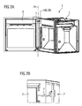
- FIG 1 shows a front of a door 3 of a household appliance 1 according to a first inventive embodiment of the present invention.
- Said household appliance 1 here is an oven 1 comprising an oven cavity defined by two opposing side walls, a back wall and an upper and lower wall and a central frontal opening.
- the door 3 is to be mounted to the oven structure for opening and closing said frontal opening of said cavity.
- the door 3 comprises electronic elements 18, particularly a user interface, switches and a display, or the like, provided for an input by the user and the display of information of the cooking program and/or oven functions.
- a kitchen appliance 1 comprises a wiring 4 routed from said oven structure 2 to said door 3 and thereby.
- a wiring 4 routing from said oven structure 2 to said door 3, and traversing a gap 19 between the oven structure 2 and the door 3 connects the electronic elements 18 of said door 3 to a not shown power supply and/or control unit provided in said oven structure 2.
- the oven 1 comprises an upper hinge mechanism 5 and a lower hinge mechanism 5', here both configured as a planar four-bar linkage.
- the upper hinge mechanism 5 is shown in FIGs 3A, 3B and 3C in more detail.
- Such four-bar linkage 5 and 5' is the simplest movable closed chain linkage. It consists of four bodies, called bars or links, connected in a loop by four joints or pivot points 6. It will be immediately understood that two opposing bars, referred to herein as the main bars 16 are each connected to either the first element or the second element. And two linkage bars each connect the two main bars 16. Generally, the joints are configured so the links move in parallel planes, and the assembly is called a planar four-bar linkage.
- a four-bar-linkage is of advantage in that the door 3 and/or the hinge mechanism 5 and 5', respectively, performs a translatory movement, which allows a particularly high opening angle, i.e. a wide opening. This is, as a four-bar-linkage 5, and 5', respectively, is not restricted to a simple rotation about a single axis.
- the door 3 hinged with such four-bar linkage 5 and 5', respectively can extend from the oven 1 during the opening movement.
- the upper hinge mechanism 5 comprises a cover 9, which here is not a carrying element of the door mechanism.
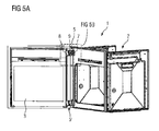
- the four-bar linkage 5 and 5' is mechanically connecting said oven structure 2 and said door 3, which may be best seen from Fig. 2A and Fig 5A .
- Said connection is arrange such that said oven structure 2 is arranged at a first side 7 of said four-bar linkage 5 and 5', respectively, and that said door 3 is arranged at a second side 8 of said four-bar linkage 5 and 5' respectively.
- Said oven 1, more particularly said upper hinge mechanism 5, further comprises a cover 9 for said wiring 4, wherein said cover 9 is pivotally attached at said first side 7 of said four-bar linkage 5, wherein at least a section of said wiring 4 is arranged between said four-bar linkage 5 and said cover 9.
- a lower hinge mechanism 5' may comprise such cover 9, particularly if a wiring 4 is traversing said vertical gap 19 at the lower part of the oven structure 2 and door 3.
- a four-bar linkage 5 and 5' comprises at least one pivot point 6, preferably four pivot points 6, and is mechanically connecting said oven structure 2 and said door 3.
- the hinge mechanism 5 and 5' allows for a pivotal movement, e.g. an opening movement, of one of the door 3 relative to the oven structure 2.
- the four-bar linkage 5 comprises a cover 9 for said wiring 4, more particularly for covering said wiring 4.
- said cover 9 protects the wiring 4 against damage, however, may also be of esthetic purpose, in that the wiring 4 is advantageously hidden from the view of the user.
- cover 9 is pivotally attached at said first side 7 of said hinge mechanism the cover 9 may be opened or closed, or tilted.
- FIG 3A and 3B the cover 9 is shown in an open stage, wherein FIGs 4A and 4B shows the cover 9 in a closed stage.
- the cover is movable and the wiring 4 is accessible easily. Accordingly, mounting of such wiring 4 is also advantageously facilitated.
- Said cover 9 is pivotally attached at said first side 7 of said hinge mechanism 5, wherein at least a section of said wiring 4 is arranged between said hinge mechanism 5 and said cover 9.
- Said section here refers to the section, which is the section of the wiring 4 routing from said oven structure 2 to said door 3, and traversing a gap 19 between the oven structure 2 and the door 3. It will, however be understood, that such wiring 4 will further route into or along the oven structure 2 and the door, in order to be connected to its target, e.g. the electric elements 18 of the door and a power circuit of the oven 1.
- the wiring 4 is arranged such that a translational movement of said wiring 4 in its longitudinal direction is allowed in a cavity-like structure provided on the inner side of the door 3, depicted by the double headed arrow.
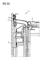
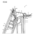
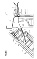
- FIGs 6A to 6E illustrate a series of sectional detailed views of a door hinged to the household appliance according to the first inventive embodiment with a four-bar linkage 5 shown at different opening positions and, particularly a hinge mechanism according to the present invention. More particularly, FIG 6A illustrates a section of the hinge 5 and the door 3 at an opening angle of about 0°; FIG 6B illustrates a section of the hinge 5 and the door 3 at an opening angle of about 22.5°, FIG 6C illustrates a section of the hinge 5 and the door 3 at an opening angle of about 45°; FIG6D illustrates a section of the hinge 5 and the door 3 at an opening angle of about 90°; and FIG 6E illustrates a section of the hinge 5 and the door 3 at an opening angle of about 130°.
- the wiring 4 here, routes from said oven structure 2 to said door 3 at the level or height of the four-bar linkage 5.
- the section which is the section of the wiring 4 routing from said oven structure 2 to said door 3 is arranged within the four-bar linkage 5 of the oven 1.
- the cover 9 here, is part of the four-bar linkage 5. It may be also taken from the provided Figs that the wiring 4 is guided inside the hinge itself, and, particularly the wiring 4 is not guided in a level above, below or next to the hinge, which may be seen in particular from Fig 4B .
- the cover 9 is pivotally attached at said first side 7 of said four-bar linkage 5.
- Said cover 9 extends from said oven structure 2 to said door 3, wherein the free end 10 of said cover 9 is or can be brought into contact with said door 3, more particularly with the second side 8.
- the free end 10 of said cover 9 refers to the side of said cover 9, opposite to its pivotal attachment 20, where the cover 9 is pivotally attached about an axis.
- the gap 19 between the oven structure 2 and the door 3 is advantageously covered, which may be taken, for example from FIG 2A .
- the wiring 4 is attached to said cover 9 and the cover 9 comprises a clamping means 11 for detachably attaching said wiring 4 to said cover 9.
- Such clamping means 11 advantageously allows for an easier mounting and secures an easier access to the wiring 4.
- the inner door 3 comprises at least one guiding means 12 for guiding of said wiring 4.
- Such guiding means preferably allows, within tolerances, only longitudinal movements of said wiring 4. This allows for an advantageous translational movement of the wiring 4 within its longitudinal extension and direction.
- the wiring 4 is held flexible with regard to the tension applied by the opening and/or closing movement of the door 3. Accordingly, the wiring 4 will upon such opening and/or closing movement of the door 3 not demolish or tear off.
- a force applied on the wiring 4 pulling or pushing said wiring in its longitudinal direction will be compensated by the free movement of the wiring 4 in its longitudinal direction.
- the door 3 further comprises a cavity 14 for the wiring 4 and the guiding means 12 are arranged at an opening 15 of said cavity 14.
- the cover 9 during the complete opening of the door 2 does not carry out the same movement of the links 17, but by a side rotates around an axis of the four bar mechanism 5 while the other side moves inside the cavity on the inner door 2, plastic door, by doing so the wiring bends at max 120° during the opening, while if the cover were to follow the: movement of the one link of the cable would bend of the 180° condition of possible breakage.
Priority Applications (6)
| Application Number | Priority Date | Filing Date | Title |
|---|---|---|---|
| EP14174654.5A EP2960412A1 (de) | 2014-06-27 | 2014-06-27 | Scharnier für ein Haushaltsgerät |
| US15/307,159 US20170122016A1 (en) | 2014-06-27 | 2015-04-01 | Hinge mechanism for household appliance |
| BR112016028136A BR112016028136A2 (pt) | 2014-06-27 | 2015-04-01 | Eletrodoméstico e mecanismo de dobradiça |
| CN201580025942.8A CN106460426B (zh) | 2014-06-27 | 2015-04-01 | 用于家用电器的铰链机构 |
| AU2015281376A AU2015281376A1 (en) | 2014-06-27 | 2015-04-01 | Hinge mechanism for household appliance |
| PCT/EP2015/057160 WO2015197209A1 (en) | 2014-06-27 | 2015-04-01 | Hinge mechanism for household appliance |
Applications Claiming Priority (1)
| Application Number | Priority Date | Filing Date | Title |
|---|---|---|---|
| EP14174654.5A EP2960412A1 (de) | 2014-06-27 | 2014-06-27 | Scharnier für ein Haushaltsgerät |
Publications (1)
| Publication Number | Publication Date |
|---|---|
| EP2960412A1 true EP2960412A1 (de) | 2015-12-30 |
Family
ID=51176092
Family Applications (1)
| Application Number | Title | Priority Date | Filing Date |
|---|---|---|---|
| EP14174654.5A Withdrawn EP2960412A1 (de) | 2014-06-27 | 2014-06-27 | Scharnier für ein Haushaltsgerät |
Country Status (6)
| Country | Link |
|---|---|
| US (1) | US20170122016A1 (de) |
| EP (1) | EP2960412A1 (de) |
| CN (1) | CN106460426B (de) |
| AU (1) | AU2015281376A1 (de) |
| BR (1) | BR112016028136A2 (de) |
| WO (1) | WO2015197209A1 (de) |
Families Citing this family (5)
| Publication number | Priority date | Publication date | Assignee | Title |
|---|---|---|---|---|
| US11286698B2 (en) * | 2019-06-27 | 2022-03-29 | Bsh Home Appliances Corporation | Cooking appliance having a load-bearing door |
| US11066862B1 (en) * | 2020-01-20 | 2021-07-20 | Component Hardware Group, Inc. | Electronic hinge |
| DE102020102316B3 (de) * | 2020-01-30 | 2020-10-22 | Hettich-Oni Gmbh & Co. Kg | Scharnier |
| DE102021208381A1 (de) * | 2021-08-03 | 2023-02-09 | BSH Hausgeräte GmbH | Gargerät mit einer in eine Tür des Gargeräts verlegten und durch ein Leitungsschutzelement geschützten Leitung |
| KR20240018266A (ko) * | 2022-08-02 | 2024-02-13 | 엘지전자 주식회사 | 조리기기 |
Citations (4)
| Publication number | Priority date | Publication date | Assignee | Title |
|---|---|---|---|---|
| WO1997035085A1 (fr) * | 1996-03-15 | 1997-09-25 | Richard Chene | Dispositif de protection et de guidage d'un composant allonge associe, au niveau de l'articulation, a deux elements rigides articules l'un a l'autre, et ses applications industrielles |
| DE202007008106U1 (de) * | 2007-06-09 | 2008-10-23 | Liebherr-Hausgeräte Lienz Gmbh | Kühl- und/oder Gefriergerät |
| DE102008029709A1 (de) | 2008-06-24 | 2010-01-07 | Al-Ko Kober Ag | Hauswasserversorgungsvorrichtung |
| US20110296761A1 (en) * | 2010-06-08 | 2011-12-08 | Wesley Wood | Hinge assembly |
Family Cites Families (2)
| Publication number | Priority date | Publication date | Assignee | Title |
|---|---|---|---|---|
| FR2878379B1 (fr) * | 2004-11-19 | 2008-04-04 | Airbus France Sas | Armoire electrique avec connexion electrique a sa porte |
| CN102913084B (zh) * | 2012-10-26 | 2015-07-08 | 何厚荣 | 一种嵌入式电冰箱门铰链 |
-
2014
- 2014-06-27 EP EP14174654.5A patent/EP2960412A1/de not_active Withdrawn
-
2015
- 2015-04-01 US US15/307,159 patent/US20170122016A1/en not_active Abandoned
- 2015-04-01 AU AU2015281376A patent/AU2015281376A1/en not_active Abandoned
- 2015-04-01 BR BR112016028136A patent/BR112016028136A2/pt not_active Application Discontinuation
- 2015-04-01 CN CN201580025942.8A patent/CN106460426B/zh not_active Expired - Fee Related
- 2015-04-01 WO PCT/EP2015/057160 patent/WO2015197209A1/en active Application Filing
Patent Citations (4)
| Publication number | Priority date | Publication date | Assignee | Title |
|---|---|---|---|---|
| WO1997035085A1 (fr) * | 1996-03-15 | 1997-09-25 | Richard Chene | Dispositif de protection et de guidage d'un composant allonge associe, au niveau de l'articulation, a deux elements rigides articules l'un a l'autre, et ses applications industrielles |
| DE202007008106U1 (de) * | 2007-06-09 | 2008-10-23 | Liebherr-Hausgeräte Lienz Gmbh | Kühl- und/oder Gefriergerät |
| DE102008029709A1 (de) | 2008-06-24 | 2010-01-07 | Al-Ko Kober Ag | Hauswasserversorgungsvorrichtung |
| US20110296761A1 (en) * | 2010-06-08 | 2011-12-08 | Wesley Wood | Hinge assembly |
Also Published As
| Publication number | Publication date |
|---|---|
| CN106460426B (zh) | 2018-12-11 |
| US20170122016A1 (en) | 2017-05-04 |
| BR112016028136A2 (pt) | 2017-08-22 |
| CN106460426A (zh) | 2017-02-22 |
| AU2015281376A1 (en) | 2016-11-10 |
| WO2015197209A1 (en) | 2015-12-30 |
Similar Documents
| Publication | Publication Date | Title |
|---|---|---|
| US20170122016A1 (en) | Hinge mechanism for household appliance | |
| US8904709B2 (en) | Movable holder | |
| US7232196B2 (en) | Refrigerator | |
| US9353562B2 (en) | Door opening and closing device | |
| US20170335611A1 (en) | Piece of furniture | |
| EP2762815A2 (de) | Haushaltsgerät mit einem Transportelement zwischen einem Körper und einer Tür dafür | |
| EP3014039B1 (de) | Scharniervorrichtung mit einer translationsbeschichtungsplatte | |
| US8253074B2 (en) | Wiring assembly for an appliance | |
| EP3438391A3 (de) | Motorisiertes scharnier | |
| EP1705328A1 (de) | Schliesser/Öffner für Möbeldrehtür | |
| CN107514200B (zh) | 家用电器 | |
| EP1821052A2 (de) | Kühlschrank mit einer Tür mit integriertem Bedienfeld | |
| EP2713109B2 (de) | Abgasverschlusssystem für einen Kochherd | |
| EP2551979A1 (de) | Stromversorgende verdrahtungsstruktur | |
| CN102233805A (zh) | 用于车辆的可打开的顶部结构 | |
| CN107405043B (zh) | 一种家用器具以及一种用于打开和关闭家用器具和门的方法 | |
| EP1826308B1 (de) | Einrichtung für das Schliessen und Öffnen eines Raumes | |
| US20180281704A1 (en) | Door edge protector device | |
| BR102018017260A2 (pt) | Dispositivo de guia para guiar um cabo para uma porta deslizante pivotante preferencialmente de duas folhas | |
| CN107542363A (zh) | 一种链式同步开窗器窗户 | |
| US20170205079A1 (en) | Door for a household appliance, and household appliance having a door | |
| KR100834463B1 (ko) | 빌트인 냉장고의 힌지 어셈블리 | |
| EP1443846B1 (de) | Gegengewicht-scharnier-vorrichtung mit vertikalbewegung für eine tür | |
| CN103089097A (zh) | 具有可摆动支承的门的家用电器 | |
| CN214548996U (zh) | 一种双门联动的烹饪装置 |
Legal Events
| Date | Code | Title | Description |
|---|---|---|---|
| PUAI | Public reference made under article 153(3) epc to a published international application that has entered the european phase |
Free format text: ORIGINAL CODE: 0009012 |
|
| AK | Designated contracting states |
Kind code of ref document: A1 Designated state(s): AL AT BE BG CH CY CZ DE DK EE ES FI FR GB GR HR HU IE IS IT LI LT LU LV MC MK MT NL NO PL PT RO RS SE SI SK SM TR |
|
| AX | Request for extension of the european patent |
Extension state: BA ME |
|
| 17P | Request for examination filed |
Effective date: 20160630 |
|
| RBV | Designated contracting states (corrected) |
Designated state(s): AL AT BE BG CH CY CZ DE DK EE ES FI FR GB GR HR HU IE IS IT LI LT LU LV MC MK MT NL NO PL PT RO RS SE SI SK SM TR |
|
| 17Q | First examination report despatched |
Effective date: 20190116 |
|
| STAA | Information on the status of an ep patent application or granted ep patent |
Free format text: STATUS: THE APPLICATION IS DEEMED TO BE WITHDRAWN |
|
| 18D | Application deemed to be withdrawn |
Effective date: 20200207 |