EP2960385B1 - A liquid dosing unit for a toilet flushing system - Google Patents
A liquid dosing unit for a toilet flushing system Download PDFInfo
- Publication number
- EP2960385B1 EP2960385B1 EP15173310.2A EP15173310A EP2960385B1 EP 2960385 B1 EP2960385 B1 EP 2960385B1 EP 15173310 A EP15173310 A EP 15173310A EP 2960385 B1 EP2960385 B1 EP 2960385B1
- Authority
- EP
- European Patent Office
- Prior art keywords
- hose
- water
- dosing
- detergent
- dosing unit
- Prior art date
- Legal status (The legal status is an assumption and is not a legal conclusion. Google has not performed a legal analysis and makes no representation as to the accuracy of the status listed.)
- Active
Links
Images


Classifications
-
- E—FIXED CONSTRUCTIONS
- E03—WATER SUPPLY; SEWERAGE
- E03D—WATER-CLOSETS OR URINALS WITH FLUSHING DEVICES; FLUSHING VALVES THEREFOR
- E03D9/00—Sanitary or other accessories for lavatories ; Devices for cleaning or disinfecting the toilet room or the toilet bowl; Devices for eliminating smells
- E03D9/02—Devices adding a disinfecting, deodorising, or cleaning agent to the water while flushing
- E03D9/03—Devices adding a disinfecting, deodorising, or cleaning agent to the water while flushing consisting of a separate container with an outlet through which the agent is introduced into the flushing water, e.g. by suction ; Devices for agents in direct contact with flushing water
- E03D9/031—Devices connected to or dispensing into the flushing pipe
-
- E—FIXED CONSTRUCTIONS
- E03—WATER SUPPLY; SEWERAGE
- E03D—WATER-CLOSETS OR URINALS WITH FLUSHING DEVICES; FLUSHING VALVES THEREFOR
- E03D9/00—Sanitary or other accessories for lavatories ; Devices for cleaning or disinfecting the toilet room or the toilet bowl; Devices for eliminating smells
- E03D9/02—Devices adding a disinfecting, deodorising, or cleaning agent to the water while flushing
- E03D9/03—Devices adding a disinfecting, deodorising, or cleaning agent to the water while flushing consisting of a separate container with an outlet through which the agent is introduced into the flushing water, e.g. by suction ; Devices for agents in direct contact with flushing water
- E03D9/033—Devices placed inside or dispensing into the cistern
- E03D9/038—Passive dispensers, i.e. without moving parts
Definitions
- the present invention relates to a liquid dosing unit for toilet flushing system.
- the present invention relates to a liquid dosing unit for providing detergent to a WC suit.
- Another system operates by allowing a solid state chemical to partly dissolve during flushing.
- the present invention preferably seeks to mitigate or eliminate one or more of the above-identified deficiencies in the art singly or in any combination and solves at least the above mentioned problems by providing liquid dosing unit for providing detergent to a water trap of a WC suit.
- An idea of the present invention is therefore to provide an efficient liquid dosing unit for providing detergent to a WC suit in a safe manner, and using a simple and robust construction.
- a WC suit should in this context be interpreted broadly as any flush toilet, either standing on the floor or wall-hung.
- a liquid dosing unit according to claim 1 for providing detergent to a WC suit comprises a dosing piping having two open ends connected via a first hose and second hose to an outlet valve of the WC suit in use.
- the liquid dosing unit further comprises a water trap arranged between said two open ends at a position vertically above said open ends.
- the first hose is connected to a first end of the water trap via a vent device.
- the water trap of the dosing piping is configured to enclose detergent, and wherein when the outlet valve is opened for flushing the WC suit, the first hose and second hose will be filled with water up to approximately the same vertical level as the water level inside a water cistern of the WC suit, and remaining air is pressed upwards through the first hose and second hose in such a way that air entrapped in the second hose will push detergent arranged at the water trap to the water filled first hose thereby forming a mix of the detergent with the water provided therein, which then flows out through the open end being connected to the first hose into the outlet valve.
- the water trap of the dosing piping is connected to one of the open ends via a first hose, and to the other open end via a second hose.
- the first hose is connected to a first end of the water trap, and the second hose is connected to a second end of the water trap.
- the first hose is connected to the first end of the water trap via a vent device.
- the vent device may form part of a funnel.
- the outlet may be an outlet valve of a water cistern enclosing flushing water.
- the dosing unit may further comprise a dosing reservoir enclosing detergent, wherein the dosing reservoir is connected to the water trap of the dosing piping for allowing detergent to flow from the dosing reservoir to the water trap.
- the dosing reservoir may be connected to the water trap by means of a fluid channel.
- the dosing reservoir has an outer shell comprising a flexible material.
- the dosing reservoir may be arranged vertically below the water trap.
- a piping for dosing liquid detergents to a WC suit comprises two open ends, of which at least one end having means for connecting to an outlet valve of the WC suit, and a water trap arranged between said two open ends at a position which in use is vertically above said open ends.
- each end comprises means for connecting to the outlet valve of the WC suit.
- the water trap may comprise means for connecting said water trap to a dosing reservoir.
- the water trap of the dosing piping is connected to one of the open ends via a first hose, and to the other open end via a second hose.
- the first hose may be connected to the first end of the water trap via a vent device.
- a WC suit comprises a liquid dosing unit according to the first embodiment.
- the following description focuses on embodiments of the present invention applicable to a liquid dosing unit for providing detergent to a WC suit.
- the WC suit may be any kind of flush toilet, such as a floor-standing flush toilet or a wall-hung flush toilet.
- a flushing system 10 of a WC suit is shown.
- the flushing system 10 is constructed to allow a user of an associated WC suit to flush the toilet after use, and for this purpose the flushing system 10 comprises a water cistern 20 and a flushing mechanism 30.
- the water cistern 20 is in fluid communication with the WC suit by means of an outlet being controlled to open by means of the flushing mechanism 30.
- the flushing mechanism 30 is constructed to open and close the outlet when the user operates a flush initiation means, such as a push button 32. Hence the outlet will be open and the water enclosed within the water cistern 20 will drain out from the outlet and into the WC suit.
- the water cistern 20 and the flushing mechanism 30 are well known and will not be described in further detail herein.
- a liquid dosing unit 100 is provided in cooperation with the flushing mechanism 30.
- the liquid dosing unit 100 comprises a dosing reservoir 190 for enclosing detergent.
- the dosing reservoir 190 is connected to a filling funnel 170, via a filling piping 180, which is used to fill the dosing reservoir 190 with detergent.
- the user By removing the flush button 32 the user, such as an attendant or a cleaner, can fill the dosing reservoir 190 with detergent by filling the funnel 170 and allowing liquid to pour down into the reservoir 190.
- the dosing reservoir 190 is further connected to a fluid channel 150 that connects the reservoir 190 to a dosing piping 120.
- the dosing reservoir 190 may contain various kinds of liquid having different viscosities, such as for example liquid detergent, cleanser and/or any other liquid cleaning agent.
- the dosing reservoir 190 may be a flexible bag which is compressible by the surrounding water pressure.
- the dosing reservoir 190 has an outer shell of which at least a part is formed by a flexible material, such as a thin sheet of plastic.
- the hydrostatic pressure of the water cistern in the WC suit will consequently compress the dosing reservoir 190, thus allowing the enclosed detergent to be pressed up through the fluid channel 150 into the dosing piping 120.
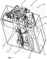
- FIG. 2 an embodiment of a liquid dosing unit 100 is shown.
- An outlet valve 130 is arranged at the lower part of the flushing system 10 and is connected to the dosing piping 120, as will be described more in detail in conjunction with Fig. 3 .
- the outlet valve 130 When pressing the flush button 32 (see Fig. 1 ), the outlet valve 130 is opened to allow the water to flush out into the WC bowl (not shown).
- the outlet valve 130 may form part of the flushing mechanism 30, e.g. by means of an overflow pipe which is raised upon flushing for opening the valve 130.
- Fig. 3 a more detailed view of the liquid dosing unit 100 is shown where the dosing reservoir 190 is hidden to facilitate understanding.
- the dosing piping 120 has two open ends 140a, 140b that connects to the outlet valve 130 of the flushing system 10, at a position being subject to the water flow only when the outlet valve 130 is open.
- the two open ends (140a, 140b) are connected to a flushing pipe downstream the outlet valve 130.
- the two open ends (140a, 140b) should be connected to a piping which is dry and filled with air between flushing, and which is wet and filled with water upon flushing.
- FIG. 4 another embodiment of a liquid dosing unit 100 is shown, in which only one end 140a is connecting to the outlet valve 130, while the other open end 140b opens to the volume inside the cistern 20. Hence, detergent arranged in the dosing piping 120 will flow into the cistern 20 upon flushing.
- the dosing piping 120 comprises a water trap 110, a first hose 121 and a second hose 122.
- the water trap 110 is arranged at a position vertically above the open ends 140a, 140b, and forms a U-bend, or an M-shaped structure.
- the water trap 110 has two open ends which are connectable to one of the open ends 140a by means of the first hose 121 and to the other open end 140b by means of the second hose 122.
- the first hose 121 is connected to a first end of the water trap 110
- the second hose 121 is connected to a second end of the water trap 110.
- the water trap 110 has a third open end located in between the two opens ends which is connectable to the fluid channel 150.
- the first hose 121, the second hose 122 and the fluid channel 150 may all be formed by fluid transporting devices, e.g. flexible hoses.
- the water trap 110 further comprises a vent device 160 arranged to act as an equalizer of the air pressure, as will be described more in detail in conjunction to Fig. 7 .
- the vent device 160 is arranged as an interface between the water trap 110 and the first hose 121.
- the function of the dosing piping 120 will now be described with reference to Fig. 6 to 8 .
- the neutral position, i.e. before a flush has been initiated, of the dosing piping 120 is shown in Fig. 6 .
- the water trap 110 is filled with detergent up to a level corresponding to the surrounding water level in the cistern, as is schematically shown in Fig. 6 . This is achieved due to the flexible shell of the dosing reservoir 190, pressing enclosed liquid to the same vertical level as the water level of the cistern 20.
- the replenishment of detergent into the water trap 110 occurs after every WC flush when the cistern (not shown) in the flushing system 10 is filling up with water. In this state, for the embodiment shown in Fig.
- the first hose 121 and the second hose 122 are filled with air since the connections are made to a dry environment downstream a sealing gasket of the outlet valve 130.
- the first hose 121 will be filled with water up to the water level of the cistern 20, while the second hose 122 will be filled with air since its connection is to the dry environment inside the outlet valve 130.
- Fig. 7 shows a schematic view of the dosing piping 120 after a flush has been initiated, i.e. when a user has initiated a flush.
- the outlet valve 130 is opened whereby water is starting to drain from the water cistern 20 out through the outlet valve 130.
- the first and second hose 121, 122 will thus be exposed to the water flow via the open ends 140a, 140b, and the hoses 121, 122 will be filled with water up to approximately the same vertical level as the water level inside the cistern 20.
- the remaining air is pressed upwards through the first and second hose 121, 122. Air entrapped in the first hose 121 of the dosing piping 120 will consequently flow out through the vent device 160.
- the height of the water column inside the hoses 121, 122 will be reduced accordingly until they are reaching an empty state.
- the water in the first hose 121 and the second hose 122 flows out, through the open ends 140a, 140b, into the outlet valve 130.
- the last water flushed into the toilet bowl is the water mixed with detergent, thus creating a fresh finish of the water that will stay in the WC suit until a next flush.
- Liquid detergent is in fact never dosed in the water while enclosed in the water cistern 20, and liquid detergent, which may be corrosive/abrasive, may consequently never be allowed to damage critical components inside the water cistern 20 such as gaskets etc. Further to this, since the dosing will occur at the end of the flushing sequence, a reduced volume of dosing will be required in order to clean the WC suit.
- the detergent will be pushed out from the first hose 121 and the associated open end 140b, into the water cistern 20.
- the detergent will reach the water of the cistern 20 rather immediately after initiating the flush, which means that the entire flushing will provide a cleaning action.
- the flushing water will expose the entire WC bowl to detergents, which means that the entire WC bowl will be cleaned.
- the dosing piping 220 comprises a water trap 210, a first hose 221 and a second hose 222.
- the water trap 210 is arranged at a position vertically above the open ends 140a, 140b.
- the water trap 210 has two open ends which are connectable to the first hose 221 and the second hose 222.
- the water trap 210 has a third open end located in between the two opens ends which is connectable to the tube 250.
- the first hose 221, the second hose 222 and the tube 250 may be formed by flexible hoses
- the water trap 210 forms an S-bend, whereby the first hose 221 and the second hose 222 are both arranged on the same side of the trap.
- the water trap 210 comprises a vent device 260 arranged to act as an equalizer of the air pressure.
- the function of the dosing piping 220 is the same as has been described above according to the embodiments of Figs. 5-8 .
Description
- The present invention relates to a liquid dosing unit for toilet flushing system. In particular the present invention relates to a liquid dosing unit for providing detergent to a WC suit.
- Different types of cleaning system to be used in a toilet flushing system of a WC suit exist on the market. One common system is provided by attaching a detergent container in the toilet bowl, e.g. under the rim or to the interior of the toilet tank by suction cups or similar. With every flush these systems will release detergent solution into the bowl, since flushing water will be allowed to enter at least a part of the container during flushing and upon exit draw detergent into the trap of the WC suit. Although such systems results in a fresh appearance in the toilet bowl, there is a risk that the containers come loose and thus falls into the bowl creating an obstacle in the toilet. In addition, the dosing volume varies over time with a higher dose of detergent solution when the container is full and a lower dose when the container starts to run empty. Furthermore, these kinds of systems require the user to arrange the container in and out of the toilet bowl when re-filling. This may be considered as a hygienic hazard, especially at public toilets.
- Another system, as described in
EP1756372 by the same inventor, operates by allowing a solid state chemical to partly dissolve during flushing. - Other systems have been proposed for which liquid detergents are used to clean the WC suits. One such system is described in
EP2696003 , wherein a feed tank has an inner chamber that contains service liquid. A siphon system connects the chamber to a branch opening that communicates with a drain hole. The described system is extremely complex, and requires the use of tanks with inner chambers in order to provide the desired functionality. Further to this, since dosing is provided by a suction force the system is not suitable for high viscous liquids. Hence, there is a need for an improved dosing unit that has a less complex construction, although providing full functionality also for high viscous liquids. Us2479842A andUS2812119A disclose liquid dosing unit a according to the state of the art, whereasUS2005/0178438A andGB211271A - Accordingly, the present invention preferably seeks to mitigate or eliminate one or more of the above-identified deficiencies in the art singly or in any combination and solves at least the above mentioned problems by providing liquid dosing unit for providing detergent to a water trap of a WC suit.
- An idea of the present invention is therefore to provide an efficient liquid dosing unit for providing detergent to a WC suit in a safe manner, and using a simple and robust construction.
- A WC suit should in this context be interpreted broadly as any flush toilet, either standing on the floor or wall-hung.
- A liquid dosing unit according to claim 1 for providing detergent to a WC suit is provided. The liquid dosing unit comprises a dosing piping having two open ends connected via a first hose and second hose to an outlet valve of the WC suit in use. The liquid dosing unit further comprises a water trap arranged between said two open ends at a position vertically above said open ends. The first hose is connected to a first end of the water trap via a vent device. The water trap of the dosing piping is configured to enclose detergent, and wherein when the outlet valve is opened for flushing the WC suit, the first hose and second hose will be filled with water up to approximately the same vertical level as the water level inside a water cistern of the WC suit, and remaining air is pressed upwards through the first hose and second hose in such a way that air entrapped in the second hose will push detergent arranged at the water trap to the water filled first hose thereby forming a mix of the detergent with the water provided therein, which then flows out through the open end being connected to the first hose into the outlet valve.
- The water trap of the dosing piping is connected to one of the open ends via a first hose, and to the other open end via a second hose. The first hose is connected to a first end of the water trap, and the second hose is connected to a second end of the water trap.
- In the embodiment according to the invention, the first hose is connected to the first end of the water trap via a vent device. The vent device may form part of a funnel.
- The outlet may be an outlet valve of a water cistern enclosing flushing water.
- The dosing unit may further comprise a dosing reservoir enclosing detergent, wherein the dosing reservoir is connected to the water trap of the dosing piping for allowing detergent to flow from the dosing reservoir to the water trap.
- The dosing reservoir may be connected to the water trap by means of a fluid channel. In an embodiment, the dosing reservoir has an outer shell comprising a flexible material.
- The dosing reservoir may be arranged vertically below the water trap.
- According to a second aspect, a piping for dosing liquid detergents to a WC suit is provided. The piping comprises two open ends, of which at least one end having means for connecting to an outlet valve of the WC suit, and a water trap arranged between said two open ends at a position which in use is vertically above said open ends. Optionally, each end comprises means for connecting to the outlet valve of the WC suit.
- The water trap may comprise means for connecting said water trap to a dosing reservoir.
- In an embodiment, the water trap of the dosing piping is connected to one of the open ends via a first hose, and to the other open end via a second hose.
- The first hose may be connected to the first end of the water trap via a vent device.
- According to another aspect, a WC suit is provided. The WC suit comprises a liquid dosing unit according to the first embodiment.
- Further objects, features and advantages will appear from the following detailed description, with reference being made to the accompanying drawings, in which:
-
Fig. 1 is an isometric view of a flushing system of a WC suit comprising a liquid dosing unit according to an embodiment; -
Fig. 2 is an isometric view of the liquid dosing unit shown inFig. 1 ; -
Fig. 3 is an isometric view showing parts of the liquid dosing unit shown inFig. 2 ; -
Fig. 4 is an isometric view showing parts of a liquid dosing unit according to an embodiment; -
Fig. 5 is an isometric view of a dosing piping according to an embodiment; -
Fig. 6 is an isometric view of a dosing piping before a flush has been initiated; -
Fig. 7 is an isometric view of a dosing piping directly after a flush has been initiated; -
Fig. 8 is an isometric view of a dosing piping after a flush has been initiated; -
Fig. 9 is an isometric view of a water trap of a dosing piping according to a further embodiment; and -
Fig. 10 is a cross-sectional view of the water trap shown inFig. 9 . - The following description focuses on embodiments of the present invention applicable to a liquid dosing unit for providing detergent to a WC suit. The WC suit may be any kind of flush toilet, such as a floor-standing flush toilet or a wall-hung flush toilet.
- In an embodiment according to
Fig. 1 , aflushing system 10 of a WC suit is shown. Theflushing system 10 is constructed to allow a user of an associated WC suit to flush the toilet after use, and for this purpose theflushing system 10 comprises awater cistern 20 and aflushing mechanism 30. Thewater cistern 20 is in fluid communication with the WC suit by means of an outlet being controlled to open by means of theflushing mechanism 30. - The
flushing mechanism 30 is constructed to open and close the outlet when the user operates a flush initiation means, such as apush button 32. Hence the outlet will be open and the water enclosed within thewater cistern 20 will drain out from the outlet and into the WC suit. - The
water cistern 20 and theflushing mechanism 30 are well known and will not be described in further detail herein. - A
liquid dosing unit 100 is provided in cooperation with theflushing mechanism 30. Theliquid dosing unit 100 comprises adosing reservoir 190 for enclosing detergent. Thedosing reservoir 190 is connected to a fillingfunnel 170, via a fillingpiping 180, which is used to fill thedosing reservoir 190 with detergent. By removing theflush button 32 the user, such as an attendant or a cleaner, can fill thedosing reservoir 190 with detergent by filling thefunnel 170 and allowing liquid to pour down into thereservoir 190. - The
dosing reservoir 190 is further connected to afluid channel 150 that connects thereservoir 190 to adosing piping 120. Thedosing reservoir 190 may contain various kinds of liquid having different viscosities, such as for example liquid detergent, cleanser and/or any other liquid cleaning agent. - The
dosing reservoir 190 may be a flexible bag which is compressible by the surrounding water pressure. For this thedosing reservoir 190 has an outer shell of which at least a part is formed by a flexible material, such as a thin sheet of plastic. The hydrostatic pressure of the water cistern in the WC suit will consequently compress thedosing reservoir 190, thus allowing the enclosed detergent to be pressed up through thefluid channel 150 into thedosing piping 120. - Now turning to
Fig. 2 , an embodiment of aliquid dosing unit 100 is shown. Anoutlet valve 130 is arranged at the lower part of theflushing system 10 and is connected to thedosing piping 120, as will be described more in detail in conjunction withFig. 3 . - When pressing the flush button 32 (see
Fig. 1 ), theoutlet valve 130 is opened to allow the water to flush out into the WC bowl (not shown). In practice, theoutlet valve 130 may form part of theflushing mechanism 30, e.g. by means of an overflow pipe which is raised upon flushing for opening thevalve 130. - Now turning to
Fig. 3 , a more detailed view of theliquid dosing unit 100 is shown where thedosing reservoir 190 is hidden to facilitate understanding. Thedosing piping 120 has twoopen ends outlet valve 130 of theflushing system 10, at a position being subject to the water flow only when theoutlet valve 130 is open. - In a further embodiment the two open ends (140a, 140b) are connected to a flushing pipe downstream the
outlet valve 130. The two open ends (140a, 140b) should be connected to a piping which is dry and filled with air between flushing, and which is wet and filled with water upon flushing. - During operation of the
liquid dosing unit 100 shown inFig. 3 , detergent arranged in the dosing piping 120 will flow into theoutlet valve 130 upon flushing. This will be further described below. - In
Fig. 4 another embodiment of aliquid dosing unit 100 is shown, in which only oneend 140a is connecting to theoutlet valve 130, while the otheropen end 140b opens to the volume inside thecistern 20. Hence, detergent arranged in the dosing piping 120 will flow into thecistern 20 upon flushing. - Now turning to
Fig. 5 , a detailed view of a part of the dosing piping 120 will be described. Thedosing piping 120 comprises awater trap 110, afirst hose 121 and asecond hose 122. Thewater trap 110 is arranged at a position vertically above the open ends 140a, 140b, and forms a U-bend, or an M-shaped structure. Thewater trap 110 has two open ends which are connectable to one of theopen ends 140a by means of thefirst hose 121 and to the otheropen end 140b by means of thesecond hose 122. Hence, thefirst hose 121 is connected to a first end of thewater trap 110, and thesecond hose 121 is connected to a second end of thewater trap 110. - In addition, the
water trap 110 has a third open end located in between the two opens ends which is connectable to thefluid channel 150. Thefirst hose 121, thesecond hose 122 and thefluid channel 150 may all be formed by fluid transporting devices, e.g. flexible hoses. - The
water trap 110 further comprises avent device 160 arranged to act as an equalizer of the air pressure, as will be described more in detail in conjunction toFig. 7 . In a first embodiment thevent device 160 is arranged as an interface between thewater trap 110 and thefirst hose 121. - The function of the dosing piping 120 will now be described with reference to
Fig. 6 to 8 . The neutral position, i.e. before a flush has been initiated, of the dosing piping 120 is shown inFig. 6 . Thewater trap 110 is filled with detergent up to a level corresponding to the surrounding water level in the cistern, as is schematically shown inFig. 6 . This is achieved due to the flexible shell of thedosing reservoir 190, pressing enclosed liquid to the same vertical level as the water level of thecistern 20. Thus, the replenishment of detergent into thewater trap 110 occurs after every WC flush when the cistern (not shown) in theflushing system 10 is filling up with water. In this state, for the embodiment shown inFig. 3 thefirst hose 121 and thesecond hose 122 are filled with air since the connections are made to a dry environment downstream a sealing gasket of theoutlet valve 130. For the embodiment shown inFig. 4 , thefirst hose 121 will be filled with water up to the water level of thecistern 20, while thesecond hose 122 will be filled with air since its connection is to the dry environment inside theoutlet valve 130. -
Fig. 7 shows a schematic view of thedosing piping 120 after a flush has been initiated, i.e. when a user has initiated a flush. When flushing the WC suit theoutlet valve 130 is opened whereby water is starting to drain from thewater cistern 20 out through theoutlet valve 130. For the embodiment shown inFig. 3 , the first andsecond hose hoses cistern 20. As the water level is rising in the first andsecond hose second hose first hose 121 of the dosing piping 120 will consequently flow out through thevent device 160. - On the other hand, air entrapped in the
second hose 122 of the dosing piping 120 will expose the dose of detergent arranged in thewater trap 110 to a pushing force towards thevent device 160, and into thefirst hose 121 being already filled with water. Hence, the detergent will form an upper layer of the water column inside thefirst hose 121. This is shown inFig. 8 . The dose of detergent that was pushed down from thewater trap 110 into thefirst hose 121 of thedosing piping 120, will now mix with the flushing water. - As the flushing continues, leading to a decreased water level inside the
cistern 20, the height of the water column inside thehoses first hose 121 and thesecond hose 122 flows out, through the open ends 140a, 140b, into theoutlet valve 130. As a result the last water flushed into the toilet bowl is the water mixed with detergent, thus creating a fresh finish of the water that will stay in the WC suit until a next flush. Liquid detergent is in fact never dosed in the water while enclosed in thewater cistern 20, and liquid detergent, which may be corrosive/abrasive, may consequently never be allowed to damage critical components inside thewater cistern 20 such as gaskets etc. Further to this, since the dosing will occur at the end of the flushing sequence, a reduced volume of dosing will be required in order to clean the WC suit. - However, for the embodiment shown in
Fig. 4 the detergent will be pushed out from thefirst hose 121 and the associatedopen end 140b, into thewater cistern 20. The detergent will reach the water of thecistern 20 rather immediately after initiating the flush, which means that the entire flushing will provide a cleaning action. Especially during the initial phase of the flushing the flushing water will expose the entire WC bowl to detergents, which means that the entire WC bowl will be cleaned. - A second embodiment of a dosing pipe is shown in
Fig. 9 and 10 . Thedosing piping 220 comprises awater trap 210, afirst hose 221 and asecond hose 222. Thewater trap 210 is arranged at a position vertically above the open ends 140a, 140b. Thewater trap 210 has two open ends which are connectable to thefirst hose 221 and thesecond hose 222. In addition, thewater trap 210 has a third open end located in between the two opens ends which is connectable to thetube 250. Thefirst hose 221, thesecond hose 222 and thetube 250 may be formed by flexible hoses - The
water trap 210 forms an S-bend, whereby thefirst hose 221 and thesecond hose 222 are both arranged on the same side of the trap. Similarly to what has been described with reference toFigs. 5-8 , thewater trap 210 comprises avent device 260 arranged to act as an equalizer of the air pressure. - As will be obvious to a person skilled in the art, the function of the dosing piping 220 is the same as has been described above according to the embodiments of
Figs. 5-8 . - Although the present invention has been described above with reference to specific embodiments, it is not intended to be limited to the specific form set forth herein. Rather, the invention is limited only by the accompanying claims and, other embodiments than the specific above are equally possible within the scope of these appended claims.
Claims (9)
- A liquid dosing unit for providing detergent to a WC suit, the liquid dosing unit comprising;a dosing piping (120, 220) having two open ends (140a, 140b), both connected via a first hose (121, 221) and second hose (122, 222) to an outlet valve (130) of the WC suit in use, said liquid dosing unit further comprises a water trap (110, 210) arranged between said two open ends (140a, 140b) at a position vertically above said open ends (140a, 140b), whereinthe water trap (110, 210) of the dosing piping (120, 220) is configured to enclose detergent, and wherein when the outlet valve (130) is opened for flushing the WC suit, the first hose (121, 221) and second hose (122, 222) will be filled with water up to approximately the same vertical level as the water level inside a water cistern (20) of the WC suit, and remaining air is pressed upwards through the first hose (121, 221) and second hose (122, 222) in such a way that air entrapped in the second hose (122, 222) will push detergent arranged at the water trap (110, 210) to the water filled first hose (121, 221) thereby forming a mix of the detergent with the water provided therein, which then flows out through the open end (140a) being connected to the first hose (121, 222) into the outlet valve (130), characterized in that the first hose (121, 122) is connected to a first end of the water trap (110, 120) via a vent device (160, 260).
- The liquid dosing unit according to claim 1, wherein the second hose (122, 222) is connected to a second end of the water trap (110, 210).
- The liquid dosing unit according to claim 1, wherein the vent device (160, 260) forms part of a funnel.
- The dosing unit according to any one of the preceding claims, wherein the outlet valve (130) connected to the water cistern (20) enclosing flushing water.
- The dosing unit according to any one of the preceding claims, further comprising a dosing reservoir (190) enclosing detergent, wherein the dosing reservoir (190) is connected to the water trap (110, 210) of the dosing piping (120, 220) for allowing detergent to flow from the dosing reservoir (190) to the water trap (110, 210).
- The liquid dosing unit according to claim 5, wherein the dosing reservoir (190) is connected to the water trap (110, 210) by means of a fluid channel (150, 250).
- The liquid dosing unit according to claim 5 or 6, wherein the dosing reservoir (190) has an outer shell comprising a flexible material.
- The liquid dosing unit according to any one of claims 5 to 7, wherein the dosing reservoir (190) is arranged vertically below the water trap (110, 210).
- A WC suit, comprising a liquid dosing unit according to any one of claims 1-8.
Applications Claiming Priority (1)
| Application Number | Priority Date | Filing Date | Title |
|---|---|---|---|
| SE1450777 | 2014-06-23 |
Publications (2)
| Publication Number | Publication Date |
|---|---|
| EP2960385A1 EP2960385A1 (en) | 2015-12-30 |
| EP2960385B1 true EP2960385B1 (en) | 2019-11-06 |
Family
ID=53496455
Family Applications (1)
| Application Number | Title | Priority Date | Filing Date |
|---|---|---|---|
| EP15173310.2A Active EP2960385B1 (en) | 2014-06-23 | 2015-06-23 | A liquid dosing unit for a toilet flushing system |
Country Status (1)
| Country | Link |
|---|---|
| EP (1) | EP2960385B1 (en) |
Families Citing this family (1)
| Publication number | Priority date | Publication date | Assignee | Title |
|---|---|---|---|---|
| GR20210100112A (en) * | 2021-02-24 | 2022-09-06 | Νεκταριος Παναγιωτη Ταλιαδουρος | Automatic toilet desinfection device |
Family Cites Families (6)
| Publication number | Priority date | Publication date | Assignee | Title |
|---|---|---|---|---|
| GB211271A (en) * | 1922-12-04 | 1924-02-21 | Joseph Beaumont Butler | Improvements in and relating to disinfecting apparatus for water-closet pans, gullies and the like |
| US2479842A (en) * | 1947-02-20 | 1949-08-23 | John D Kirwan | Means for sterilizing flush type toilet bowls |
| US2812119A (en) * | 1954-09-20 | 1957-11-05 | James N Bethune | Pressure responsive automatic dispensing device |
| US20050178438A1 (en) * | 2004-02-18 | 2005-08-18 | Renner Brian K. | Flexible and extendable plumbing trap device |
| ES2358034T3 (en) | 2004-05-05 | 2011-05-05 | Ifö Sanitär AB | DOSAGE DEVICE FOR TOILET. |
| ITMI20121418A1 (en) | 2012-08-08 | 2014-02-09 | Oliveira & Irmao Sa | DISPENSER DEVICE FOR A SERVICE LIQUID FOR A RINSE CASSETTE |
-
2015
- 2015-06-23 EP EP15173310.2A patent/EP2960385B1/en active Active
Non-Patent Citations (1)
| Title |
|---|
| None * |
Also Published As
| Publication number | Publication date |
|---|---|
| EP2960385A1 (en) | 2015-12-30 |
Similar Documents
| Publication | Publication Date | Title |
|---|---|---|
| KR20120086245A (en) | Jet powered toilet flushing system | |
| EA039580B1 (en) | Device for toilets | |
| US8904571B2 (en) | Fresh flush recycling toilet | |
| US9869080B2 (en) | Cleaning liquid dispenser | |
| EP2696003A1 (en) | Flush tank service liquid dispenser device | |
| EP2434064A1 (en) | Automatic distributor device using a metering pump with adjustable volume | |
| EP2960385B1 (en) | A liquid dosing unit for a toilet flushing system | |
| WO2009143392A1 (en) | Water conservation system | |
| EA038271B1 (en) | Flushing assembly, sanitary-ware comprising such assembly and method for flushing a bowl of such sanitary-ware | |
| US20160083950A1 (en) | Flush toilet with build-in one-way valve system for use in unclogging clogs and for efficient water-saving flush operations and related methods. | |
| EP3114286B1 (en) | Sanitary ware product comprising dispenser | |
| US8359679B2 (en) | Toilet clog removal and cleaning system | |
| KR200480074Y1 (en) | Cleaner discharger for toilet bowl | |
| CN104712040A (en) | Controllable liquid separating device | |
| WO2013123194A1 (en) | High pressure low liquid volume waste disposal system | |
| EP2207938B1 (en) | Improvements in and relating to sanitation | |
| CN103882925A (en) | Vacuum auxiliary toilet bowl with delayed air exhaust closing system | |
| US8484769B1 (en) | System for delivering chemicals to a toilet bowl | |
| US20080302823A1 (en) | Coupling device and kit for a cleaning fluid dispenser | |
| JP6505005B2 (en) | Cleaning method and construction method of water storage tank | |
| EP3219863B1 (en) | A wc suite | |
| EP2650450B1 (en) | Dispenser device of a service liquid for a flushing tank | |
| RU2610122C2 (en) | Dosing device of auxiliary fluid for flush tank and flush tank with such dosing device | |
| CN219604475U (en) | Automatic clean vacuum toilet | |
| GB2466924A (en) | Liquid dispenser and flexible container arrangement for use in a cistern |
Legal Events
| Date | Code | Title | Description |
|---|---|---|---|
| PUAI | Public reference made under article 153(3) epc to a published international application that has entered the european phase |
Free format text: ORIGINAL CODE: 0009012 |
|
| AK | Designated contracting states |
Kind code of ref document: A1 Designated state(s): AL AT BE BG CH CY CZ DE DK EE ES FI FR GB GR HR HU IE IS IT LI LT LU LV MC MK MT NL NO PL PT RO RS SE SI SK SM TR |
|
| AX | Request for extension of the european patent |
Extension state: BA ME |
|
| 17P | Request for examination filed |
Effective date: 20160630 |
|
| RBV | Designated contracting states (corrected) |
Designated state(s): AL AT BE BG CH CY CZ DE DK EE ES FI FR GB GR HR HU IE IS IT LI LT LU LV MC MK MT NL NO PL PT RO RS SE SI SK SM TR |
|
| RAP1 | Party data changed (applicant data changed or rights of an application transferred) |
Owner name: GEBERIT INTERNATIONAL AG |
|
| STAA | Information on the status of an ep patent application or granted ep patent |
Free format text: STATUS: EXAMINATION IS IN PROGRESS |
|
| 17Q | First examination report despatched |
Effective date: 20181129 |
|
| GRAP | Despatch of communication of intention to grant a patent |
Free format text: ORIGINAL CODE: EPIDOSNIGR1 |
|
| STAA | Information on the status of an ep patent application or granted ep patent |
Free format text: STATUS: GRANT OF PATENT IS INTENDED |
|
| INTG | Intention to grant announced |
Effective date: 20190531 |
|
| GRAS | Grant fee paid |
Free format text: ORIGINAL CODE: EPIDOSNIGR3 |
|
| GRAA | (expected) grant |
Free format text: ORIGINAL CODE: 0009210 |
|
| STAA | Information on the status of an ep patent application or granted ep patent |
Free format text: STATUS: THE PATENT HAS BEEN GRANTED |
|
| AK | Designated contracting states |
Kind code of ref document: B1 Designated state(s): AL AT BE BG CH CY CZ DE DK EE ES FI FR GB GR HR HU IE IS IT LI LT LU LV MC MK MT NL NO PL PT RO RS SE SI SK SM TR |
|
| REG | Reference to a national code |
Ref country code: GB Ref legal event code: FG4D |
|
| REG | Reference to a national code |
Ref country code: CH Ref legal event code: EP Ref country code: AT Ref legal event code: REF Ref document number: 1198902 Country of ref document: AT Kind code of ref document: T Effective date: 20191115 |
|
| REG | Reference to a national code |
Ref country code: DE Ref legal event code: R096 Ref document number: 602015040967 Country of ref document: DE |
|
| REG | Reference to a national code |
Ref country code: IE Ref legal event code: FG4D |
|
| REG | Reference to a national code |
Ref country code: FI Ref legal event code: FGE |
|
| REG | Reference to a national code |
Ref country code: SE Ref legal event code: TRGR |
|
| REG | Reference to a national code |
Ref country code: NL Ref legal event code: MP Effective date: 20191106 |
|
| REG | Reference to a national code |
Ref country code: NO Ref legal event code: T2 Effective date: 20191106 |
|
| REG | Reference to a national code |
Ref country code: LT Ref legal event code: MG4D |
|
| PG25 | Lapsed in a contracting state [announced via postgrant information from national office to epo] |
Ref country code: BG Free format text: LAPSE BECAUSE OF FAILURE TO SUBMIT A TRANSLATION OF THE DESCRIPTION OR TO PAY THE FEE WITHIN THE PRESCRIBED TIME-LIMIT Effective date: 20200206 Ref country code: GR Free format text: LAPSE BECAUSE OF FAILURE TO SUBMIT A TRANSLATION OF THE DESCRIPTION OR TO PAY THE FEE WITHIN THE PRESCRIBED TIME-LIMIT Effective date: 20200207 Ref country code: LT Free format text: LAPSE BECAUSE OF FAILURE TO SUBMIT A TRANSLATION OF THE DESCRIPTION OR TO PAY THE FEE WITHIN THE PRESCRIBED TIME-LIMIT Effective date: 20191106 Ref country code: NL Free format text: LAPSE BECAUSE OF FAILURE TO SUBMIT A TRANSLATION OF THE DESCRIPTION OR TO PAY THE FEE WITHIN THE PRESCRIBED TIME-LIMIT Effective date: 20191106 Ref country code: PL Free format text: LAPSE BECAUSE OF FAILURE TO SUBMIT A TRANSLATION OF THE DESCRIPTION OR TO PAY THE FEE WITHIN THE PRESCRIBED TIME-LIMIT Effective date: 20191106 Ref country code: PT Free format text: LAPSE BECAUSE OF FAILURE TO SUBMIT A TRANSLATION OF THE DESCRIPTION OR TO PAY THE FEE WITHIN THE PRESCRIBED TIME-LIMIT Effective date: 20200306 Ref country code: LV Free format text: LAPSE BECAUSE OF FAILURE TO SUBMIT A TRANSLATION OF THE DESCRIPTION OR TO PAY THE FEE WITHIN THE PRESCRIBED TIME-LIMIT Effective date: 20191106 |
|
| PG25 | Lapsed in a contracting state [announced via postgrant information from national office to epo] |
Ref country code: IS Free format text: LAPSE BECAUSE OF FAILURE TO SUBMIT A TRANSLATION OF THE DESCRIPTION OR TO PAY THE FEE WITHIN THE PRESCRIBED TIME-LIMIT Effective date: 20200306 Ref country code: RS Free format text: LAPSE BECAUSE OF FAILURE TO SUBMIT A TRANSLATION OF THE DESCRIPTION OR TO PAY THE FEE WITHIN THE PRESCRIBED TIME-LIMIT Effective date: 20191106 Ref country code: HR Free format text: LAPSE BECAUSE OF FAILURE TO SUBMIT A TRANSLATION OF THE DESCRIPTION OR TO PAY THE FEE WITHIN THE PRESCRIBED TIME-LIMIT Effective date: 20191106 |
|
| PG25 | Lapsed in a contracting state [announced via postgrant information from national office to epo] |
Ref country code: AL Free format text: LAPSE BECAUSE OF FAILURE TO SUBMIT A TRANSLATION OF THE DESCRIPTION OR TO PAY THE FEE WITHIN THE PRESCRIBED TIME-LIMIT Effective date: 20191106 |
|
| PG25 | Lapsed in a contracting state [announced via postgrant information from national office to epo] |
Ref country code: DK Free format text: LAPSE BECAUSE OF FAILURE TO SUBMIT A TRANSLATION OF THE DESCRIPTION OR TO PAY THE FEE WITHIN THE PRESCRIBED TIME-LIMIT Effective date: 20191106 Ref country code: ES Free format text: LAPSE BECAUSE OF FAILURE TO SUBMIT A TRANSLATION OF THE DESCRIPTION OR TO PAY THE FEE WITHIN THE PRESCRIBED TIME-LIMIT Effective date: 20191106 Ref country code: RO Free format text: LAPSE BECAUSE OF FAILURE TO SUBMIT A TRANSLATION OF THE DESCRIPTION OR TO PAY THE FEE WITHIN THE PRESCRIBED TIME-LIMIT Effective date: 20191106 Ref country code: CZ Free format text: LAPSE BECAUSE OF FAILURE TO SUBMIT A TRANSLATION OF THE DESCRIPTION OR TO PAY THE FEE WITHIN THE PRESCRIBED TIME-LIMIT Effective date: 20191106 Ref country code: EE Free format text: LAPSE BECAUSE OF FAILURE TO SUBMIT A TRANSLATION OF THE DESCRIPTION OR TO PAY THE FEE WITHIN THE PRESCRIBED TIME-LIMIT Effective date: 20191106 |
|
| REG | Reference to a national code |
Ref country code: DE Ref legal event code: R097 Ref document number: 602015040967 Country of ref document: DE |
|
| REG | Reference to a national code |
Ref country code: AT Ref legal event code: MK05 Ref document number: 1198902 Country of ref document: AT Kind code of ref document: T Effective date: 20191106 |
|
| PG25 | Lapsed in a contracting state [announced via postgrant information from national office to epo] |
Ref country code: SK Free format text: LAPSE BECAUSE OF FAILURE TO SUBMIT A TRANSLATION OF THE DESCRIPTION OR TO PAY THE FEE WITHIN THE PRESCRIBED TIME-LIMIT Effective date: 20191106 Ref country code: SM Free format text: LAPSE BECAUSE OF FAILURE TO SUBMIT A TRANSLATION OF THE DESCRIPTION OR TO PAY THE FEE WITHIN THE PRESCRIBED TIME-LIMIT Effective date: 20191106 |
|
| PLBE | No opposition filed within time limit |
Free format text: ORIGINAL CODE: 0009261 |
|
| STAA | Information on the status of an ep patent application or granted ep patent |
Free format text: STATUS: NO OPPOSITION FILED WITHIN TIME LIMIT |
|
| 26N | No opposition filed |
Effective date: 20200807 |
|
| PG25 | Lapsed in a contracting state [announced via postgrant information from national office to epo] |
Ref country code: SI Free format text: LAPSE BECAUSE OF FAILURE TO SUBMIT A TRANSLATION OF THE DESCRIPTION OR TO PAY THE FEE WITHIN THE PRESCRIBED TIME-LIMIT Effective date: 20191106 Ref country code: AT Free format text: LAPSE BECAUSE OF FAILURE TO SUBMIT A TRANSLATION OF THE DESCRIPTION OR TO PAY THE FEE WITHIN THE PRESCRIBED TIME-LIMIT Effective date: 20191106 |
|
| REG | Reference to a national code |
Ref country code: DE Ref legal event code: R119 Ref document number: 602015040967 Country of ref document: DE |
|
| PG25 | Lapsed in a contracting state [announced via postgrant information from national office to epo] |
Ref country code: MC Free format text: LAPSE BECAUSE OF FAILURE TO SUBMIT A TRANSLATION OF THE DESCRIPTION OR TO PAY THE FEE WITHIN THE PRESCRIBED TIME-LIMIT Effective date: 20191106 Ref country code: IT Free format text: LAPSE BECAUSE OF FAILURE TO SUBMIT A TRANSLATION OF THE DESCRIPTION OR TO PAY THE FEE WITHIN THE PRESCRIBED TIME-LIMIT Effective date: 20191106 |
|
| REG | Reference to a national code |
Ref country code: CH Ref legal event code: PL |
|
| GBPC | Gb: european patent ceased through non-payment of renewal fee |
Effective date: 20200623 |
|
| PG25 | Lapsed in a contracting state [announced via postgrant information from national office to epo] |
Ref country code: LU Free format text: LAPSE BECAUSE OF NON-PAYMENT OF DUE FEES Effective date: 20200623 |
|
| REG | Reference to a national code |
Ref country code: BE Ref legal event code: MM Effective date: 20200630 |
|
| PG25 | Lapsed in a contracting state [announced via postgrant information from national office to epo] |
Ref country code: IE Free format text: LAPSE BECAUSE OF NON-PAYMENT OF DUE FEES Effective date: 20200623 Ref country code: GB Free format text: LAPSE BECAUSE OF NON-PAYMENT OF DUE FEES Effective date: 20200623 Ref country code: CH Free format text: LAPSE BECAUSE OF NON-PAYMENT OF DUE FEES Effective date: 20200630 Ref country code: LI Free format text: LAPSE BECAUSE OF NON-PAYMENT OF DUE FEES Effective date: 20200630 Ref country code: FR Free format text: LAPSE BECAUSE OF NON-PAYMENT OF DUE FEES Effective date: 20200630 |
|
| PG25 | Lapsed in a contracting state [announced via postgrant information from national office to epo] |
Ref country code: BE Free format text: LAPSE BECAUSE OF NON-PAYMENT OF DUE FEES Effective date: 20200630 Ref country code: DE Free format text: LAPSE BECAUSE OF NON-PAYMENT OF DUE FEES Effective date: 20210101 |
|
| PG25 | Lapsed in a contracting state [announced via postgrant information from national office to epo] |
Ref country code: TR Free format text: LAPSE BECAUSE OF FAILURE TO SUBMIT A TRANSLATION OF THE DESCRIPTION OR TO PAY THE FEE WITHIN THE PRESCRIBED TIME-LIMIT Effective date: 20191106 Ref country code: MT Free format text: LAPSE BECAUSE OF FAILURE TO SUBMIT A TRANSLATION OF THE DESCRIPTION OR TO PAY THE FEE WITHIN THE PRESCRIBED TIME-LIMIT Effective date: 20191106 Ref country code: CY Free format text: LAPSE BECAUSE OF FAILURE TO SUBMIT A TRANSLATION OF THE DESCRIPTION OR TO PAY THE FEE WITHIN THE PRESCRIBED TIME-LIMIT Effective date: 20191106 |
|
| PG25 | Lapsed in a contracting state [announced via postgrant information from national office to epo] |
Ref country code: MK Free format text: LAPSE BECAUSE OF FAILURE TO SUBMIT A TRANSLATION OF THE DESCRIPTION OR TO PAY THE FEE WITHIN THE PRESCRIBED TIME-LIMIT Effective date: 20191106 |
|
| PGFP | Annual fee paid to national office [announced via postgrant information from national office to epo] |
Ref country code: NO Payment date: 20230608 Year of fee payment: 9 |
|
| PGFP | Annual fee paid to national office [announced via postgrant information from national office to epo] |
Ref country code: SE Payment date: 20230612 Year of fee payment: 9 Ref country code: FI Payment date: 20230613 Year of fee payment: 9 |