EP2960204A1 - Hydrogen storage by reversible hydrogenation of pi-conjugated substrates - Google Patents
Hydrogen storage by reversible hydrogenation of pi-conjugated substrates Download PDFInfo
- Publication number
- EP2960204A1 EP2960204A1 EP15178631.6A EP15178631A EP2960204A1 EP 2960204 A1 EP2960204 A1 EP 2960204A1 EP 15178631 A EP15178631 A EP 15178631A EP 2960204 A1 EP2960204 A1 EP 2960204A1
- Authority
- EP
- European Patent Office
- Prior art keywords
- hydrogen
- conjugated
- extended
- hydrogenation
- liquid
- Prior art date
- Legal status (The legal status is an assumption and is not a legal conclusion. Google has not performed a legal analysis and makes no representation as to the accuracy of the status listed.)
- Granted
Links
- IVHUNDJOMKXTST-UHFFFAOYSA-N CN1C2C3N=CCNC3C3NCCNC3C2NCCC1 Chemical compound CN1C2C3N=CCNC3C3NCCNC3C2NCCC1 IVHUNDJOMKXTST-UHFFFAOYSA-N 0.000 description 1
- LKWDJOYHDIUBLP-UHFFFAOYSA-N C[n]1c2c(c3ccccc3[nH]3)c3c(c(cccc3)c3[nH]3)c3c2c2c1cccc2 Chemical compound C[n]1c2c(c3ccccc3[nH]3)c3c(c(cccc3)c3[nH]3)c3c2c2c1cccc2 LKWDJOYHDIUBLP-UHFFFAOYSA-N 0.000 description 1
- HXTIDLAZPXGZKP-UHFFFAOYSA-N Cc(cccc12)c1[nH]c1c2c([n](C)c2c3cccc2)c3c2c1c1ccccc1[n]2C Chemical compound Cc(cccc12)c1[nH]c1c2c([n](C)c2c3cccc2)c3c2c1c1ccccc1[n]2C HXTIDLAZPXGZKP-UHFFFAOYSA-N 0.000 description 1
- QQWXDAWSMPLECU-UHFFFAOYSA-N c(cc1)cc2c1[nH]c1c2ccc2c1c1ccccc1[nH]2 Chemical compound c(cc1)cc2c1[nH]c1c2ccc2c1c1ccccc1[nH]2 QQWXDAWSMPLECU-UHFFFAOYSA-N 0.000 description 1
- UJOBWOGCFQCDNV-UHFFFAOYSA-N c(cc1)cc2c1[nH]c1ccccc21 Chemical compound c(cc1)cc2c1[nH]c1ccccc21 UJOBWOGCFQCDNV-UHFFFAOYSA-N 0.000 description 1
Images


Classifications
-
- C—CHEMISTRY; METALLURGY
- C01—INORGANIC CHEMISTRY
- C01B—NON-METALLIC ELEMENTS; COMPOUNDS THEREOF; METALLOIDS OR COMPOUNDS THEREOF NOT COVERED BY SUBCLASS C01C
- C01B3/00—Hydrogen; Gaseous mixtures containing hydrogen; Separation of hydrogen from mixtures containing it; Purification of hydrogen
- C01B3/0005—Reversible uptake of hydrogen by an appropriate medium, i.e. based on physical or chemical sorption phenomena or on reversible chemical reactions, e.g. for hydrogen storage purposes ; Reversible gettering of hydrogen; Reversible uptake of hydrogen by electrodes
- C01B3/001—Reversible uptake of hydrogen by an appropriate medium, i.e. based on physical or chemical sorption phenomena or on reversible chemical reactions, e.g. for hydrogen storage purposes ; Reversible gettering of hydrogen; Reversible uptake of hydrogen by electrodes characterised by the uptaking medium; Treatment thereof
- C01B3/0015—Organic compounds; Solutions thereof
-
- B—PERFORMING OPERATIONS; TRANSPORTING
- B01—PHYSICAL OR CHEMICAL PROCESSES OR APPARATUS IN GENERAL
- B01J—CHEMICAL OR PHYSICAL PROCESSES, e.g. CATALYSIS OR COLLOID CHEMISTRY; THEIR RELEVANT APPARATUS
- B01J3/00—Processes of utilising sub-atmospheric or super-atmospheric pressure to effect chemical or physical change of matter; Apparatus therefor
- B01J3/02—Feed or outlet devices therefor
-
- Y—GENERAL TAGGING OF NEW TECHNOLOGICAL DEVELOPMENTS; GENERAL TAGGING OF CROSS-SECTIONAL TECHNOLOGIES SPANNING OVER SEVERAL SECTIONS OF THE IPC; TECHNICAL SUBJECTS COVERED BY FORMER USPC CROSS-REFERENCE ART COLLECTIONS [XRACs] AND DIGESTS
- Y02—TECHNOLOGIES OR APPLICATIONS FOR MITIGATION OR ADAPTATION AGAINST CLIMATE CHANGE
- Y02E—REDUCTION OF GREENHOUSE GAS [GHG] EMISSIONS, RELATED TO ENERGY GENERATION, TRANSMISSION OR DISTRIBUTION
- Y02E60/00—Enabling technologies; Technologies with a potential or indirect contribution to GHG emissions mitigation
- Y02E60/30—Hydrogen technology
- Y02E60/32—Hydrogen storage
Landscapes
- Chemical & Material Sciences (AREA)
- Organic Chemistry (AREA)
- Chemical Kinetics & Catalysis (AREA)
- Health & Medical Sciences (AREA)
- General Health & Medical Sciences (AREA)
- Engineering & Computer Science (AREA)
- Combustion & Propulsion (AREA)
- Inorganic Chemistry (AREA)
- Filling Or Discharging Of Gas Storage Vessels (AREA)
- Hydrogen, Water And Hydrids (AREA)
- Organic Low-Molecular-Weight Compounds And Preparation Thereof (AREA)
Abstract
Description
- This application is (a) a continuation-in-part of U.S. Patent Application No. _______, filed April 27, 2004 and entitled "Hydrogen Storage by Reversible Hydrogenation of Pi-Conjugated Substrates", which is a continuation-in-part of
U.S. Patent Application No. 10/430,246, filed May, 6, 2003 U.S. Patent Application No. 10/430,246, filed May, 6, 2003 - This invention relates to processes for the reversible hydrogenation of pi-conjugated substrates to provide for the storage and release of hydrogen at practical operating temperatures and pressures, particularly for supplying hydrogen to fuel cells. Hydrogen is a widely used chemical commodity in the chemical and petroleum processing industries, but with the relatively recent development of fuel cells it is increasingly also being considered as a viable "clean" energy source. Stationary fuel cells can be supplied with hydrogen from on-site natural gas reformers or via existing hydrogen pipeline sources. However, for mobile vehicular systems, a practical and effective method for storing hydrogen to power an on-board fuel cell or a hydrogen fuelled internal combustion engine is required. The transport of hydrogen as a cryogenic liquid, although technologically well established, is an energy-intensive process which results in a significantly higher cost of the delivered gas. Hydrogen is also conventionally transported as a compressed gas in steel cylinders, but the storage capacity is relatively low. Higher gravimetric storage amounts, but at relatively low volumetric densities, can now be achieved with hydrogen gas at very high pressures up to 10,000 psi (690 bar) in light-weight containers made of very high strength composite materials. There are significant energy costs in thus compressing the gas as well as potential issues regarding consumers' acceptance of systems that contain hydrogen at such elevated pressures.
- It is thus necessary and highly desirable to devise a means of storing and delivering hydrogen safely, at an adequate gravimetric and volumetric storage density and with a minimal consumption of energy. This may be accomplished by "containing" the hydrogen in a suitable solid, or potentially even in liquid sorbent media, compositions which have a substantial but reversible affinity for the gas. The gas is contacted with the sorbent at modest temperatures and hydrogen pressures and is released for use as required, by lowering the system's hydrogen partial pressure at the same or a higher temperature. Hydrogen uptake by the sorbent is usually an exothermic process, while the release of hydrogen for use requires at least the corresponding input of thermal energy which can be met from the fuel cell's or internal combustion engine's waste heat. Thus, in contrast to compressed hydrogen-based storage systems, the necessary energy needed for containing the hydrogen (i.e. its heat of adsorption) can thus largely be met without significant consumption of higher grade electrical energy for compression. Also, there is a considerably increased safety factor in a sorbed hydrogen. Since any desorption process is endothermic, it will be naturally self-retarding and the hydrogen will not spontaneously totally desorb without an external input of heat.
- The present invention is also directed to a dispensing device that allows dispensing of a first liquid and retrieval of a second liquid and methods of use thereof. In one embodiment, the dispensing device is used to dispense a first liquid comprising an at least partially hydrogenated pi-conjugated substrate and retrieve a second liquid comprising the pi-conjugates substrate.
- The challenge in this sorbent approach to hydrogen storage is in devising the appropriate functioning sorbent media. Much of the research on containing hydrogen in this way has focused on the property of various metals and metal alloys to reversibly chemically combine with hydrogen to form metal hydrides. Representative examples are FeTi; TiV alloys; LaNi5; various magnesium-nickel combinations; and sodium alanate, NaAlH4, which can reversibly dissociate in the presence of some catalysts into Al, NaH and H2. There is a substantial literature on metal hydrides and while research is still being actively pursued in this field for instance on tri- and multi-metal hydrides, demonstrated gravimetric hydrogen capacities are still well short of the 6+ wt % hydrogen that are required for vehicular hydrogen storage.
- There have recently been a number of claims of hydrogen storage by various forms of carbon: as single wall nanotubes by A. C. Dillon et al. in Nature 386, 377-379 (1997); and as graphitic nanofibers by Chambers et al. in J. Phys. Chem. B 102, 4253-4256 (1998). However, these and other literature claims of a substantial hydrogen containment by carbons [see A. C. Dillon and M. J. Heben in Appl. Phys. A 72, 133-142 (2001)] have not been specifically confirmed by other investigators; the field of hydrogen sorption by carbons has remained an open area of research. In this context,
Cooper and Pez in US 2002/0096048 have reported that intimate combinations of hydrogen reactive metals or metal alloys, or metal hydrides with various forms of substantially graphitic carbon, i.e. carbon-metal hybrids, display a reversible uptake of hydrogen at near ambient conditions and are useful as pressure-swing and temperature-swing sorbents for the storage of hydrogen. The observed reversible facile hydrogen reactivity is theorized to occur either by a "hydrogen-spillover" mechanism or by a partial reversible metal-catalyzed hydrogenation of the unsaturated graphitic carbon structures. - A recent report by S. J. Cho et al. in ACS Fuel Chemistry Division Preprints 47(2), 790-791 (2002) claims the adsorption of hydrogen by the hydrochloric acid-doped conducting polymers polyaniline and polypyrrole. These polymers are exposed to high pressure (1350 psia, 93 bar) hydrogen at 25°C resulting in an apparent slow uptake of hydrogen gas. The hydrogen gas is desorbed by heating the sample to 200°C at an unspecified gas pressure. The authors speculate that the hydrogen is physically adsorbed (ie., the H-H bond remains intact) in the porous conducting polymers. Samples that were not treated with hydrochloric acid, which apparently induces porosity in the polymer samples, did not show any uptake of hydrogen. No metal catalysts are reported to be present in the material and no indication for chemical adsorption of hydrogen or catalytic hydrogenation of the polymer is given in this publication.
- The possibility of storing hydrogen via the catalytic hydrogenation and then dehydrogenation of common aromatic molecules such as benzene or toluene has long been disclosed as a means of storing the hydrogen. With a theoretical hydrogen storage capacity of about 7 weight percent, the systems seem attractive. But while this chemistry is performed routinely in chemical plants there are numerous difficulties in utilizing it in a practical hydrogen storage device.
- The principal obstacles are as follows:
- With the appropriate metal catalysts, the hydrogenation of benzene, toluene, naphthalene and related one or two six-membered ring aromatics to the corresponding saturated cyclic hydrocarbons, cyclohexane, methylcyclohexane and decalin, respectively, can be conducted at relatively mild conditions, e.g. ~100°C and ∼100 psi (6.9 bar) of hydrogen pressure, where it is thermodynamically very favorable. However, dehydrogenation of the above cited corresponding alkanes to produce hydrogen gas at the about 20 psia (1.5 bar) and higher delivery pressures that are required for use in fuel cells is, as currently carried out, a highly endothermic process and thus requires the use of higher reaction temperatures that are not easily obtainable from fuel cells, especially those presently used in vehicles, as well as a significant input of energy. Thus,
US. 4,567,033 to Kesten et al. describes a method of "freeing" molecular hydrogen from methylcyclohexane by its dehydrogenation to toluene at 316°C, the required thermal input being supplied by a combustion of a considerable portion of the by-product hydrogen. - Additionally, the common one or two six-membered ring aromatic molecules are quite volatile as are their hydrogenated products. While the hydrogenation can be conducted in a closed system, the production of product hydrogen from the reverse reaction fundamentally requires that there be some means of totally separating the gas from the reaction's organic volatile components. While technically possible, this requires a further unit operation which increases the complexity and hence the cost of the hydrogen storage process.
- There have been several attempts to provide practical processes for storing hydrogen via a reversible hydrogenation of aromatics.
US 6,074,447 to Jensen et al. describes a means of dehydrogenating a hydrocarbon to an aromatic and hydrogen in the presence of a particular iridium-based molecular complex catalyst at preferably 190°C or higher. Specifically described hydrocarbons are methylcyclohexane, decalin, dicyclohexyl, and cyclohexane (for which the corresponding aromatic products are toluene, naphthalene, biphenyl and benzene); there is no mention of any larger hydrogenated hydrocarbons or the polycyclic aromatic hydrocarbons or other pi-conjugated molecules of this invention. Additionally, the envisaged substrates of this prior art are clearly volatile at reaction temperatures and the reaction chamber is thus necessarily provided with a membrane that is highly selective for the passage of hydrogen as compared to the other volatile reaction components which are retained in the reaction chamber. - N. Kariya et al. have recently reported in Applied Catalysis A, 233, 91-102 (2002) what is described to be an efficient generation of hydrogen from liquid cycloalkanes such as cyclohexane, methylcyclohexane and decalin over platinum and other platinum-containing catalysts supported on carbon. The process is carried out at from about 200°C to 400°C under "wet-dry multiphase conditions", which involves intermittently contacting the saturated liquid hydrocarbon with the heated solid catalyst in a way such that the catalyst is alternately wet and dry. Because of local superheating and other cited factors the dehydrogenation reaction is rendered more efficient in terms of improved reaction kinetics but because of the reaction thermodynamics (vide infra) it still requires the use of relatively high temperatures for a high conversion of the cyclohexane to the corresponding aromatic molecule. This basic process is elaborated on in several Japanese patent applications (e.g.
JP20001110437 JP2002134141 - R.O. Loufty and E.M. Vekster, in "Investigation of Hydrogen Storage in Liquid Organic Hydrides", Proceedings of the International Hydrogen Energy Forum 2000, Munich Germany, 2000; pp. 335-340, have reported the dehydrogenation of decalin in a membrane reactor where the very low conversion (∼15%) of decalin, even at 300°C, is greatly enhanced by the selective separation of hydrogen by the membrane and its removal from the reactor.
-
JP2002134141 A - In spite of the work described above, there remains a need for processes for the reversible hydrogenation of pi-conjugated substrates to provide for the storage and release of hydrogen at practical operating temperatures and pressures, particularly for supplying hydrogen to fuel cells.
- New methods and devices may be required for efficiently dispensing the hydrogenated substrates to fuel cells.
- Common fuel dispensing devices such as those used to dispense gasoline for automobiles and the like, referred to as gasoline dispensing nozzles, comprise a handle which is in communication with a gasoline supply means, a manual operating lever to control the flow of fuel to the vehicle, and a dispensing conduit for dispensing the gasoline to one or more gasoline tanks on board the vehicle. Common gasoline dispensing nozzles are described in
U.S. Patent No. 5,197,523 to Fink, Jr. et al. andU.S. Patent No. 5,435,356 to Rabinovich . - Such fuel dispensing and on board storage tanks are satisfactory for a fuel such as gasoline, diesel or alcohol, since the by-products of the combustion process are emitted into the atmosphere. However, conventional fuel dispensing and on-board storage tanks are less attractive for recyclable liquid fuels where the spent fuel must be stored on board the vehicle until it can be retrieved and regenerated.
- Recyclable liquid fuels that have generated recent interest include liquid aromatic compounds such as benzene, toluene and naphthalene ("the aromatic substrates"), which undergo reversible hydrogenation to form cyclohexane, methylcyclohexane and decalin ("the hydrogenated substrates"), respectively. The hydrogenated substrates are provided to a dehydrogenation system and hydrogen fuel cell where, under suitable conditions, the hydrogenated substrates dehydrogenate to form hydrogen for use by the fuel cell, and the aromatic substrate is recovered. For example,
U.S. Patent No. 6,074,447 to Jensen describes dehydrogenating methylcyclohexane, decalin, dicyclohexyl, and cyclohexane to toluene, naphthalene, biphenyl and benzene, respectively, in the presence of a particular iridium based molecular complex catalyst at preferably 190°C or higher. - An attractive feature of using a hydrogen carrier based on liquid aromatic compounds is that it offers the possibility of using the existing liquid hydrocarbon-fuel infrastructure for hydrogenating, delivering and storing the liquid-phase hydrogen carrier. In contrast, the delivery and storage of hydrogen as either a cryogenic liquid or a compressed gas would require different methods of storage and transportation. In addition, the use of compressed hydrogen would incur considerable energy costs in compressing the gas as well as potential issues regarding consumers' acceptance of systems that contain hydrogen at such elevated pressures.
- In principle, liquid hydrogenated substrates are easily transported using conventional methods for liquid transport and distribution (pipelines, railcars, tanker trucks). Likewise, liquid hydrogenated substrates can be delivered to a mobile or stationary fuel cell using a conventional gasoline dispensing nozzle. At the point of use, a dehydrogenation reaction is carried out to generate hydrogen for use by the fuel cell and the dehydrogenated substrate (i.e., the aromatic substrate). The aromatic substrate is collected in a recovery tank and is later returned to a hydrogenation facility where it is reacted with hydrogen to regenerate the hydrogenated substrate.
- Chem. Eng., 21 (March 2003) describes the use of liquid organic hydrides by hydrogenating benzene and naphthalene to form cyclohexane and decalin, and transporting the hydrogenated compounds to user's site.
- A process for delivering hydrogen contained by a liquid substrate ("liquid hydride") to a fuel cell vehicle or a stationary power source using the existing fossil fuel infrastructure is described in G. Pez, Toward New Solid and Liquid Phase Systems for the Containment, Transport and Deliver of Hydrogen," May 2003, (see http://www.eere.energy.gov/hydrogenandfuelcells/pdfs/solid_liquid_carriers_pres_air_pro d.pdf). The Pez reference describes a process where the liquid substrate is hydrogenated at a hydrogenation plant and the resultant liquid hydride is delivered to a multi-vehicle fueling station or stationary power source using existing gasoline or diesel delivery methods. The Pez reference notes that a lightweight mid-size fuel cell vehicle could be driven about 400 miles on 18 gallons of a liquid hydride having a density of about 1 g/cc and containing 6 wt.% of desorbable hydrogen.
- S. Hodoshima et al., Int. J. Hydrogen Energy 28: 1255-1262 (2003) describes using decalin and naphthalene as the hydrogenated substrate and aromatic substrate, respectively. The Hodoshima reference further teaches that naphthalene could be hydrogenated with hydrogen generated by electrolysis of water using renewable energy sources such as windpower.
- E. Newsome et al., Int. J. Hydrogen Energy 23: 905-909 (1998) describes using methylcyclohexane and toluene as the hydrogenated substrate and aromatic substrate, respectively, and further teaches that the liquid hydride could be formed and stored in summer months for use in winter months.
- Typically, the hydrogenated substrate is delivered to a storage tank onboard the vehicle with the mobile fuel cell or nearby the stationary fuel cell where it is stored until hydrogen is required. The hydrogenated substrate is then contacted with a suitable dehydrogenation catalyst under dehydrogenation conditions to provide hydrogen for the fuel cell and the corresponding aromatic substrate is directed to a recovery tank (see G. Pez, Toward New Solid and Liquid Phase Systems for the Containment, Transport and Deliver of Hydrogen," May 2003, http://www.eere.energy.gov/hydrogenandfuelcells/pdfs/solid_liquid_carriers_pres_air_pro d.pdf). Presumably, when the onboard liquid hydride storage tank is sufficiently empty and/or the recovery tank is sufficiently full, the dehydrogenated form of the liquid carrier is removed from the recovery tank and the liquid hydride is added to the storage tank.
- The following relate to methods for storing the hydrogenated substrates and the corresponding aromatic substrates:
- Japanese Patent Application Publication No.
JP2003321201 A - Japanese Patent Application Publication No.
JP2004026582 A -
U.S. Patent No. 6,544,400 to Hockaday et al . describes a two-chamber storage device comprising a bladder for storing a hydrogen fuel source and a reaction chamber, where an elastic membrane separates the fuel bladder and the reaction chamber. - Using present technology, process for refueling a vehicular fuel cell comprises attaching a liquid hydride fuel dispensing nozzle to the storage compartment to dispense the hydrogenated substrate (see, e.g.,
U.S. Patent No. 5,197,523 to Fink, Jr. et al .). Presumably, the aromatic substrate is removed from the recovery tank by "pumping" it out by a separate retrieving means. This complicates the refueling process and increases the refueling time and these would be expected to meet with consumer resistance. - Accordingly, there is a need for a dispenser that can both dispense a first liquid and retrieve a second liquid.
- Citation of any reference in
Section 2 is not an admission that the reference is prior art to the present application. - The present invention provides a means of capturing and thereby storing hydrogen by its chemical reaction, conducted at moderate temperatures, in the presence of a catalyst, with a substrate having an extended pi-conjugated molecular structure as defined herein to yield the corresponding substantially hydrogenated form of the pi-conjugated system. As used herein, hydrogenate, including in its various forms, means to add hydrogen to saturate unsaturated bonds, and does not include hydrogen cleavage of molecules or hydrogenolysis (ie., breaking of carbon-carbon or carbon-heteroatom linkages). A delivery of the stored hydrogen is accomplished simply by reducing the pressure of hydrogen, and/or raising the temperature, both of which promote the corresponding dehydrogenation reaction.
- In one embodiment, the pi-conjugated substrates of our invention can be reversibly catalytically hydrogenated at milder reaction conditions and with a lesser expenditure of energy than those of the prior art, i.e. principally benzene, toluene and naphthalene. The extended pi-conjugated substrate and its hydrogenated derivative are for the most part relatively large molecules, and are therefore relatively involatile, thus being easily separable from the product hydrogen stream. While a high degree of hydrogenation and dehydrogenation is advantageous to be an effective and practical hydrogen storage system, at least partial hydrogenation and dehydrogenation, preferably wherein the reversible hydrogen uptake of the extended pi-conjugated substrate is at least 1.0 % of by weight of the at least partially hydrogenated substrate, yields an effective and practical hydrogen storage economy.
- As demonstrated herein by quantum mechanics based thermodynamics calculations and supporting experimental data, a reversible hydrogenation of extended pi-conjugated aromatic molecules is generally thermodynamically more favorable; it can be carried out at a lower temperature than is possible with the commonly used as cited in
Section 2, one, two, or three six-membered ring aromatic substrates of the prior art. Essentially, the modulus of the heat or enthalpy of the (exothermic) hydrogenation reaction and of the (endothermic) dehydrogenation step is reduced, thus resulting in a hydrogenation/dehydrogenation system which is more easily reversible at modest and practical temperatures. An added advantage of using the extended pi-conjugated substrates is that they and their hydrogenated derivatives are far less volatile, thus precluding the need for a separate unit operation for totally separating these from the product hydrogen thus greatly simplifying the overall hydrogen storage equipment and its process of operation. - In one embodiment, the present invention also relates to methods for using a dispenser for dispensing a first liquid and retrieving a second liquid.
- The present invention also relates to methods for using a dispenser of the invention for dispensing a first liquid and retrieving a second liquid.
- In one embodiment, the invention relates to a process for dispensing a first liquid to a first compartment and retrieving a second liquid situated in a second compartment, comprising:
- placing a dispenser in communication with a first compartment and a second compartment, the dispenser comprising a first conduit having an orifice for dispensing the first liquid and a second conduit having an orifice for retrieving a second liquid in direction countercurrent to the first liquid;
- transferring the first liquid through the first conduit into the first compartment; and
- transferring the second liquid situated in the second compartment into the second conduit.
- The present invention also relates to a fueling process. In one embodiment, the invention relates to a fueling process comprising:
- placing a dispenser comprising a first conduit having an orifice for dispensing a first liquid comprising an at least partially hydrogenated pi-conjugated substrate and a second conduit having an orifice for retrieving a second liquid comprising a pi-conjugated substrate in flow communication with a first compartment and a second compartment;
- transferring a portion of the first liquid residing in the first compartment into a hydrogen generator and contacting the portion of the stored first liquid with a dehydrogenation catalyst under dehydrogenation conditions sufficient to provide hydrogen and the second liquid;
- transferring at least a portion of the second liquid into the second compartment;
- transferring the first liquid through the first conduit into the first compartment; and
- transferring the second liquid through the second conduit.
- The present invention also relates to a dispenser useful for dispensing a first liquid and retrieving a second liquid.
- In one embodiment, the present invention relates to a dispenser for dispensing a first liquid and retrieving a second liquid comprising a first conduit having an orifice for dispensing the first liquid, and a second conduit having an orifice for retrieving a second liquid in direction countercurrent to the first liquid.
- The details of the invention are set forth in the accompanying figures, detailed description and examples below. Although any methods and materials similar or equivalent to those described herein can be used in the practice or testing of the present invention, illustrative methods and materials are now described. Other features, objects and advantages of the invention will be apparent from the description and from the claims.
-
-
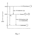
Fig. 1 is a comparison of the enthalpy change for hydrogenating three "isolated" double bonds, exemplified by three molecules of cyclohexene, to cyclohexane and of hydrogenating benzene to the same product. ΔH3 is the pi-conjugation or resonance stabilization energy for benzene. -
Fig. 2 shows the enthalpy changes, ΔH°, associated with the formation of conformers as exemplified by the hydrogenation of naphthalene to cis- and trans-decalin. -
Fig. 3 shows the hydrogenation reaction enthalpies,
-
Fig. 4 shows the hydrogenation of certain extended pi-conjugated substrates where all of the unsaturated linkages of the pi-unsaturated substrate have been hydrogenated. -
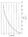
Fig. 5 shows the calculated dehydrogenation temperature for a 95.24% equilibrium conversion of the saturated, fully hydrogenated carrier molecule, A-H2n back to the pi-conjugated substrate, A, at 1 atm. H2 pressure, i.e., where K ofEquation 3 is 0.05 atm.-n. Calc. = calculated using the ab initio DFT density functional theory method; Exp. = calculated from experimental data. The numbers refer to the hydrogenation substrate shown in Tables 1a-1d. *Calculated using our experimental enthalpy data (Example 13) and computationally derived entropy values. -
Fig.6 is a plot of the calculated standard enthalpies of hydrogenation
-
Fig. 7 is a plot of the calculated standard enthalpies of hydrogenation
PM 3 method was used for the calculation. -
Fig. 8 is a plot of the hydrogen adsorption vs. time of a sample (Example 3) of coronene with 5% Rh on carbon catalyst. -
Fig. 9 is a plot of the hydrogen desorption vs. time of a sample (Example 3) of coronene with 5% Rh on carbon catalyst. -
Fig. 10 is a plot of the hydrogen adsorption vs. time, for two consecutive cycles, of a sample (Example 4) of coronene with palladium metal catalyst. -
Fig. 11 is a plot of the hydrogen desorption vs. time,cycle # 1, of a sample (Example 4) of coronene with palladium metal catalyst. -
Fig. 12 is a plot of the hydrogen desorption vs. time,cycle # 2, of a sample (Example 4) of coronene with palladium metal catalyst. -
Fig. 13 is a plot for 5 consecutive cycles of the hydrogen desorption vs. time of a sample (Example 10) of N-ethylcarbazole with ruthenium on lithium aluminate and palladium on lithium aluminate catalysts. -
Fig. 14 is a plot of the hydrogen desorption vs. time of a sample (Example 11) of N-ethylcarbazole with palladium on lithium aluminate catalyst. -
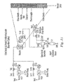
Fig. 15 is a schematic of a continuous flow dehydrogenation reactor (Example 12). -
Fig 16 is a plot of the hydrogen desorption at 180°C vs. time of a sample (Example 15) of 1-ethyl-2-methylindole with palladium on alumina catalyst. -
Fig 17 is a plot of the hydrogen desorption at 160°C vs. time of a sample (Example 15) of 1-ethyl-2-methylindole with palladium on alumina catalyst. -
Fig. 18 is a plot of the hydrogen adsorption vs. time of a sample (Comparative Example 1) of pentacene with 5% Rh on carbon catalyst. -
Fig. 19 is a plot of the hydrogen desorption vs. time of a sample (Comparative Example 1) of pentacene with 5% Rh on carbon catalyst. -
FIG. 20 depicts an exemplary dispenser of the invention having a dispensing conduit adjacent to a retrieving conduit. -
FIG. 21 depicts an exemplary dispenser of the invention having a dispensing conduit that is not adjacent to a retrieving conduit. -
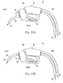
FIG. 22a depicts an exemplary dispenser of the invention having a retrieving orifice proximate to the dispenser handle and having a dispensing conduit. -
FIG. 22b depicts an exemplary dispenser of the invention having a dispensing orifice proximate to the dispenser handle and having a retrieving conduit. -
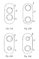
FIG. 23a depicts an exemplary dispenser of the invention having a dispensing orifice adjacent to a retrieving orifice. -
FIG. 23b depicts an exemplary dispenser of the invention having a dispenser orifice adjacent that is not adjacent to a retrieving orifice. -
FIG. 24a depicts an exemplary dispenser of the invention having a retrieving orifice that is larger than the dispensing orifice. -
FIG. 24b depicts an exemplary dispenser of the invention having a retrieving orifice that is smaller than the dispensing orifice. -
FIG. 25a depicts an exemplary dispenser of the invention having a dispenser orifice situated within a retrieving orifice. -
FIG. 25b depicts an exemplary dispenser of the invention having a retrieving orifice situated within a dispensing orifice. -
FIG. 26 depicts an exemplary embodiment of the invention where a dispenser of the invention is in communication with a tank having a first liquid and second liquid separated by a barrier. -
FIG. 27 depicts an exemplary embodiment of the invention where a dispenser of the invention is in communication with a first tank and a second tank. - Provided herein is a process for the storage of hydrogen by its reversible chemical reaction with extended pi-conjugated substrates. It may be performed with extended pi-conjugated molecular structures as herein defined and with reaction parameters, as illustrated by the following computational and experimental examples.
- Pi-conjugated (often written in the literature using the Greek letter Π) molecules are structures which are characteristically drawn with a sequence of alternating single and double bonds. But this representation of the chemical bonding is only a means of recognizing such molecules by their classical valence bond structures. It does not alone provide a description of their useful properties in the context of this invention for which concepts of modern molecular orbital theory of bonding need to be invoked.
- In molecular orbital theory, the classically written single bond between two atoms is referred to as a σ-bond, and arises from a bonding end-on overlap of two dumbbell shaped "p" electron orbitals. It is symmetrical along the molecular axis and contains the two bonding electrons. In a "double" bond, there is, in addition, a side-on overlap of two "p" orbitals that are perpendicular to the molecular axis and is described as a pi-bond (or "Π-bond"). It also is populated by two electrons but these electrons are usually less strongly held, and more mobile. A molecule that comprises (is depicted as) a sequence of alternating single and double bonds is described as a "pi-conjugated system" in the sense that the pi-electrons of the double bonds can be delocalized over this sequence for the entire molecule. The consequence of this is that the pi-conjugated molecule has a lower overall energy, i.e. is more stable than if its pi-electrons were confined to or localized on the double bonds. This is well evident experimentally in the simplest pi-conjugated system, trans-1,3-butadiene. The heat (enthalpy) change at standard conditions (1 atm. pressure, 25°C) for hydrogenating the two double bonds to yield butane is -56.24 kcal/mole as compared to a total of -60.06 kcal/mole for hydrogenating two molecules of 1-butene to the same end product. Thus, 1,3-butadiene is more stable by 3.82 kcal/mol because of the internal conjugation, as evidenced by the lower modulus (absolute value) of the negative enthalpy of hydrogenation. As illustrated in
Fig. 1 , a much larger stabilization from pi-conjugation of 35.6 kcal/mol can be calculated in the same way for benzene compared to cyclohexane and is referred to as its aromatic stabilization energy. - The practical consequence of this additional stability that can be achieved with extended pi-conjugated substrates is that it brings these closer in energy to their corresponding saturated or fully hydrogenated derivatives, i.e. minimizing ΔH2 in
Fig. 1 thus making possible hydrogen storage via catalytic hydrogenation/dehydrogenation processes that are more easily reversible at mild temperatures and are less energy intensive. - This concept can be quantified in terms of the basic thermodynamic parameters, enthalpy (ΔH), entropy (ΔS), Gibbs free energy (ΔG), and the equilibrium constant K, for the reversible hydrogenation reaction of substrate A to A-H2n:

by the familiar thermodynamic relationship:
where R is the ideal gas constant, T is the reaction temperature (in degrees Kelvin) and
where
where the terms in [ ] refer to concentration or partial pressure of A and A-H2n and PH2 designates the hydrogen partial pressure. - The enthalpy change (ΔH) for hydrogenation of A to A-H2n at the standard state of 25°C and 1 atm. H2 will henceforth be referred to as


ca 150°C in the presence of appropriate catalysts, the reverse reaction - an extensive catalytic dehydrogenation of cyclohexane and decahydronaphthalene (decalin) at about 1 atm. H2 is only possible at much higher temperatures (vide infra). For a practical H2, storage system it is desirable to have the dehydrogenation provide H2 at 1-3 atm. atca 200°C for potential use in conjunction with a hydrogen internal combustion engine and preferably at lower temperatures, e.g., 80°C-120°C, where present day PEM fuel cells operate. The lower dehydrogenation temperatures are also desirable for maintaining the reacting system in a condensed state (solid or preferably liquid) and minimizing coking and other problems that are often encountered in higher temperature catalytic dehydrogenation reactions. - For the hydrogenation of benzene to cyclohexane, a system which has been described in the prior art for hydrogen storage, the experimental enthalpy change at standard conditions (1 atm. pressure gas, 25°C), ΔHo, is -16.42 kcal/mol H2; ΔG at 80°C is -6.17 kcal/mol H2, with a corresponding K=2.91 x 10¹¹ atm.-1 and approaches a zero value only at about 280°C (where K = 1.1 atm-3). As shown in
Fig.5 , the temperature required for a 95.24% conversion of cyclohexane to benzene (1), at equilibrium (K = 0.05) for this system at 1 atm. H2 is 319°C (Table 1 a). - For the hydrogenation of naphthalene (liquid), C10H8, to cis- decalin (liquid), C10H18, (which has also been investigated as a hydrogen storage system), the experimental ΔH°= -15.13 kcal/mol H2 and ΔG at 80°C is -4.87 kcal/mol H2 and approaches zero only at about 235°C (where K = 0.8 atm.-1). The temperature for 95.24% conversion of naphthalene, C10H8, to cis- decalin C10H18, at equilibrium (K = 0.05) for this system at 1 atm. H2 is 319°C (see Table 1 a, 2). Therefore, it is very clear that with the reversible hydrogenation systems of the prior art, a recovery of hydrogen that is stored by hydrogenation will only be possible at quite elevated temperatures. And in addition, as noted earlier, these prior art systems all comprise highly volatile components, which would require another unit operation for their separation from hydrogen.
- Described here are extended pi-conjugated substrates which can advantageously be reversibly hydrogenated at much milder conditions than for benzene and naphthalene and are not appreciably volatile, thus precluding the need of a complex separation process for the evolved recovered hydrogen. In one embodiment, these hydrogenated extended pi-conjugated substrates can be dehydrogenated at temperatures below about 250°C while at hydrogen partial pressures of greater than about 1.449 psia (0.1 bar) and even at pressures in excess of 14.49 psia (1.0 bar) as will be shown by the examples. This is highly unexpected since temperatures required to effect dehydrogenation increase significantly with increasing hydrogen partial pressures. An added advantage of the extended pi-conjugated substrates of this invention is the relative involatility of the substrate, both in hydrogenated and dehydrogenated states, as this eases the separation of the released hydrogen for subsequent usage.
- In another embodiment, these hydrogenated extended pi-conjugated substrates can be dehydrogenated at temperatures below about 300°C while at hydrogen partial pressures of greater than about 1.449 psia (0.1 bar) and even at pressures in excess of 14.49 psia (1.0 bar) as will be shown by the examples.
-
Equations Equation 1. The enthalpy and entropy change terms forEquation 1, ΔH and ΔS, respectively, are arrived at from the corresponding experimentally or computationally derived thermodynamic functions for the reaction components, A, A-H2n and hydrogen. Temperature and hydrogen pressure are process parameters, which for a set of values of ΔH and ΔS, may be chosen for attaining at reaction equilibrium a high conversion of A to A-H2n: for example, [A-H2n]/[A]>20 for the H2 storage step and conversely [A-H2n]/[A]<0.05 for the reverse reaction. Given ΔH and ΔS information for pi-conjugated systems, it should therefore be possible to select a suitable hydrogenation substrate and design an H2 storage and delivery process. Unfortunately, such data is only available for very few systems, i.e., benzene, naphthalene, pyridine, pyrrole, and the corresponding perhydrogenated molecules (cf. Tables 1a and 1b). We have noticed from an analysis of the available data (and confirmed by subsequent calculations) that for the hydrogenation of aromatic substrates, ΔS which is largely representative of the loss of the translational entropy of the hydrogen molecule, is close to -30 cal/deg. mole of H2. The enthalpy change, ΔH (expressed as kcal/mol H2) inEquation 1, is therefore the quantity that mostly determines for pi-conjugated substrates the reversibility of this chemistry at specified hydrogenation and dehydrogenation process parameters. Since ΔH varies only slightly with temperature, ΔH°, the enthalpy change for the reaction with all components at their standard state (1 atm., 25°C), is employed here as a first-order indication of the reversibility and hence the usefulness of a given hydrogenation/dehydrogenation reaction system for H2 storage and delivery. - In one embodiment, the invention relates to a practical hydrogen storage device that operates via a reversible hydrogenation of a pi-conjugated system for which the change in enthalpy at standard conditions (referred to hereinafter as


- In another embodiment, the invention relates to a practical hydrogen storage device that operates via a reversible hydrogenation of a pi-conjugated system, the change in enthalpy at standard conditions of hydrogenation of the substrate as determined experimentally is within the range of about -7.0 to about -20.0 kcal/mol H2.
- The hydrogenation of the pi-conjugated substrate molecule may in some cases yield more than one product of the same overall chemical composition. There may be found structural isomers or conformers of the product molecule that differ only in the relative disposition of its carbon-hydrogen bonds or of other atoms or groups of atoms in the molecule. The conformers will each have different energies (standard heats of formation, ΔH°f), the thermodynamically most stable conformer having the lowest ΔH°f. This occurs in the hydrogenation of naphthalene, which can result in the formation of the two conformers, both saturated molecules, cis- decalin and trans-decalin, which as illustrated by
Fig. 2 , differ in the relative disposition of the two C-H linkages, along the common carbon-carbon bond. Commercial decalin contains a 67:33 distribution of cis and trans conformers, the latter where the C-H bonds are on opposite sides of the common C-C linkage, is more stable by ca. 3 kcal/mol. Larger, fully hydrogenated pi-conjugated molecules and particularly those containing nitrogen heteroatoms can potentially have a myriad of conformers which may differ in energy (ΔH°) by several kcal/mol vis-à-vis the most stable conformer. In practice, the formation of conformers will depend on the conditions at which the catalytic hydrogenation of the pi-conjugated substrate is carried out; lower hydrogenation reaction temperatures favoring the least stable conformer molecules. As is clear from the illustration for naphthalene in (Fig. 2 ), the formation of such non-equilibrium conformers provides a means of desirably lowering the hydrogenation enthalpy
- A difficulty in defining suitable pi-conjugated substrates for hydrogen storage is that experimentally derived hydrogenation enthalpy change data is available only for relatively small pi-conjugated molecules. Our basis for defining the following classes of extended pi-conjugated substrates suitable for the reversible hydrogenation/dehydrogenation processes of our invention is in terms of their enthalpy of hydrogenation as derived from quantum mechanical (QM) calculations. The calculations were done at two levels of theory: 1) Using the PM3 (Parametric Method 3) semi-empirical QM algorithm for a prediction of ΔH° for the hydrogenation reaction expressed by
Equation 1; and 2) employing an ab initio ("from the beginning") QM algorithm that utilizes density functional theory (DFT) which allowed a prediction of both ΔH and ΔS for the hydrogenation reaction at any temperature without input of experimental data. For a review of these computational techniques, see "Computational Chemistry - A Practical Guide for Applying Techniques to Real World Problems" by D. Young, Wiley - Interscience, NY, 2001, the entire contents of which are expressly incorporated herein by reference. - The PM3 method was implemented using the commercial software program package Spartan 02 and Spartan 04 by Wavefunction Inc., Irvine, CA. In performing the calculations, all structures were first fully optimized in their molecular geometry by an energy minimization procedure. The conformation of the hydrogenated species was carefully chosen so that the adjacent hydrogen atoms are present alternatively at opposite sides of the aromatic planes; the ultimate criteria being a selection of the conformer of lowest energy. It is known that PM3 incorrectly yields the heat of formation for the H2 molecule. However, by replacing it with the experimental value of the heat of formation for H2 at its standard state, we obtain the value of heat of reaction at standard conditions, ΔH°, for hydrogenation that is in fair agreement with the available experimental data. For example, for hydrogenation of benzene (gas) to cyclohexane
- (gas), the calculated value of ΔH° is -18.16 kcal/mol H2 (exp. -16.42 kcal/mol H2); for hydrogenation of naphthalene (gas) to trans-decalin (gas), the calculated value is -17.03 kcal/mol H2 (exp. -15.96 kcal/mol H2). While a similar level of accuracy was also found for other all carbon-hydrogen only aromatic compounds, the technique appears to be somewhat less satisfactory when applied to compounds with nitrogen or other hetero atoms for which the ab initio DFT method is much more reliable (see below). Nevertheless, PM3 works satisfactorily for providing the correct trend of ΔH°f values over a range of similar molecules. And it is the only method available for very large systems (>about seven, five or six-membered rings) where the computational cost for the more sophisticated and higher precision ab initio methods would be impractical. Therefore we have only used the PM3 method for calculating ΔH° of hydrogenation for the series of polyaromatic hydrocarbons (
Figs. 6 and7 ) which comprise relatively larger molecules (greater than about seven five- or six-membered rings) for which the computational cost of the ab initio DFT methodology would be prohibitive. - In the ab initio DFT computational approach, the molecular geometry is as before carefully selected to ensure that the lowest energy conformer has been chosen. The final geometry optimization is carried out using the B3LYP functional with a 6-311G** or higher basis set (see
Chapter 
- The harmonic oscillator approximation is known to result in an over-estimate of the vibrational frequencies and thus the vibrational enthalpy, Hv. This situation is commonly remedied (see "
Computational Chemistry Chapter 11") by modifying the calculated Hv's for the organic molecules by the scaling factor s, which for a hydrogenation of aromatic molecules we have empirically determined as 0.8. This as described ab initio computational method provides hydrogenation enthalpies, ΔH° which agree well (within + 1 kcal/mol H2) with available experimental data (cf. Table 1 data for benzene (1), naphthalene (2 cis, 3 trans), etc.). The entropy change for hydrogenation, ΔS is given by:
- In practice, for the hydrogenation of pi-unsaturated compounds the translational entropy for hydrogen, ST(H2), largely predominates and as assumed earlier, ΔSH2 at standard condition for many systems is close to -30 cal/deg. mol. The thus estimated values of ΔH and ΔS along with
Equations Fig. 5 for a number of pi-conjugated substrates. - Experimentally determined values for the hydrogenation enthalpies can be obtained from measuring the heat of combustion of hydrogenated and dehydrogenated substrates to products of known thermodynamic properties (i.e., CO2, H2O, NO, or N2) using known in the art or methods as described in Example 13 of the present application.
- For the purposes of this description and the claims, "extended pi-conjugated substrates" are defined to include extended polycyclic aromatic hydrocarbons, extended pi-conjugated substrates with nitrogen heteroatoms, extended pi-conjugated substrates with heteroatoms other than nitrogen, pi-conjugated organic polymers or oligomers, ionic pi-conjugated substrates, pi-conjugated monocyclic substrates with multiple nitrogen heteroatoms, pi-conjugated substrates with at least one triple bonded group and selected fractions of coal tar or pitch that have as major components the above classes of pi-conjugated substrates, or any combination of two or more of the foregoing. These classes are further defined below, and non-limiting embodiments of species falling within these classes are provided.
- In one embodiment, the modulus of the standard enthalpy change of hydrogenation of the extended pi-conjugated substrate,

- The

Fig. 3 , Tables 1a-1d and the dehydrogenation temperature data (Fig. 5 ) provide an instructive and useful classification of pi-conjugated substrates in terms of their suitability for hydrogen storage. Referring to the "Exp." column of data inFig. 3 , for the substrates/reaction systems 

- With confidence in the precision of ab initio DFT method we claim the use of pi-unsaturated substrates of this invention molecules for which the modulus of

Fig. 5 : On the basis of both experimental and ab initio DFT method calculations, the hydrogenated forms ofmolecules 1 to 5 are expected to be at equilibrium, ca. 95% in the dehydrogenated form at about above about 240°C, which is indicated by the horizontal dotted line at 1 atm. H2 pressure. The fully hydrogenated reaction systems of this invention as exemplified inFig. 5 by pi-conjugated substrates 6 to 19 are expected to undergo a ca. 95% dehydrogenation under 1 atm. H2 at temperatures below about 250°C. Surprisingly, some of these molecules are predicted to de-hydrogenate even below 100°C; (this would also require appropriately reactive catalysts). - In another embodiment, we claim the use of pi-unsaturated substrates of this invention for which the modulus of

- While the extended pi-conjugated substrates useful for reversible hydrogenation in accordance with this invention are represented as the unhydrogenated form of the substrate molecule, the actual substrate subjected to hydrogenation may already have some degree of hydrogenation. For purposes of the hydrogenation/dehydrogenation cycle to store and release hydrogen and to re-hydrogenate the substrate, the extended pi-conjugated substrate may exist and be cycled between different levels of full or partial hydrogenation and dehydrogenation as to either the individual molecules or as to the bulk of the substrate, depending upon the degree of conversion of the hydrogenation and dehydrogenation reactions. The levels of hydrogenation and dehydrogenation of the starting extended pi-conjugated substrate and the at least partially hydrogenated extended pi-conjugated substrate will be selected to provide the requisite level of hydrogen storage and release under practical operating conditions and requirements. The substrates useful according to this invention may also have various ring substituents, such as -n-alkyl, -branched-chain alkyl, -alkoxy, -nitrile, -ether and - polyether, which may improve some properties such as melting temperature of the substrate while at the same time not adversely interfering with the hydrogenation/dehydrogenation equilibrium but due to the increased weight resulting in some loss of hydrogen storage capacity of the substrate. Preferably, any of such substituent groups would have 12 or less carbons. As discussed below in the section on "Pi-conjugated Substrates with Multiple Nitrogen Heteroatoms" alkyl substituents (and it's expected that also alkoxy substituents) will actually favorably slightly lower the modulus of the heat of hydrogenation,

- Classes of extended pi-conjugated substrates suitable for the processes of this invention are further and more specifically defined as follows:
- Extended Polycyclic Aromatic Hydrocarbons (EPAH). For the purposes of this description and the claims, "extended polycyclic aromatic hydrocarbons" are defined to be those molecules having either (1) a polycyclic aromatic hydrocarbon comprising a fused ring system having at least four rings wherein all rings of the fused ring system are represented as 6-membered aromatic sextet structures; or (2) a polycyclic aromatic hydrocarbon of more than two rings comprising a six-membered aromatic sextet ring fused with a 5-membered ring.
- The EPAH molecules represent a particular class of extended pi-conjugated substrates since their pi electrons are largely delocalized over the molecule. While, on a thermodynamic basis, generally preferred are the larger molecules (i.e., those with considerably more than four rings), the value of the standard enthalpy change of hydrogenation,


Chapter 6, it is a general principle that the stability of isomers of fused ring substrates increases with the number of aromatic sextets. For instance anthracene

- Thus, according to this invention, for a EPAH of a given number of fused rings the structural isomer that is represented with the largest number of aromatic sextets will be preferred as a hydrogenation/dehydrogenation extended pi-conjugated substrate. EPAH's with a large number of aromatic sextets are preferred structures in accordance with this invention. These two criteria provide a useful but only qualitative indication of the relative

- Quantum mechanics calculations utilizing the PM3 methodology provide a more useful and quantitative but only approximate prediction of the

Fig. 6 for the represented molecules. - In
Fig. 6 , Curve I shows the variation of


Fig. 6 , Curve II). We have observed a more pronounced effect of fused ring number on
Fig. 6 , Curve III). Increasing the number of fused rings from pyrene (4 rings) to coronene (7 rings) results in a decrease of 1.72 kcal/mol H2 in the modulus of the ΔH° of hydrogenation. This curve portraying larger and still larger polyaromatic hydrocarbons suggests that the ΔH° of hydrogenation of a single sheet of graphite will be of the order of about -8 to about -11 kcal/mol H2 and represents the ultimate in large molecular size (if not the ideal) potentially reversibly hydrogenable polyaromatic hydrocarbons. The large effect of polyaromatic hydrocarbon shape on the ΔH° of hydrogenation can also be illustrated by comparing the ΔH° of hydrogenation values for the three 13-ring polyaromatic hydrocarbons inFig. 6 . There is a span of over 5.5 kcal/mol H2 between the (PM3 derived) ΔH° of hydrogenation of hexabenzocoronene (C42H18, -12.9 kcal/mol H2):
Fig. 6 for which the (PM3) ΔH° of hydrogenation is -18.4 kcal/mol H2. - Other non-limiting examples polycyclic aromatic hydrocarbons particularly useful according this invention include pyrene, perylene, coronene, ovalene, picene and rubicene.
- As noted above, EPAH's comprising 5-membered rings are defined to be those molecules comprising a six-membered aromatic sextet ring fused with a 5-membered ring. We have also discovered that, surprisingly, these pi-conjugated substrates comprising 5-membered rings would provide effective reversible hydrogen storage substrates according to this invention since they have a lower modulus of the ΔH° of hydrogenation than the corresponding conjugated system in a 6-membered ring. The calculated (PM3) ΔH° for hydrogenation of three linear, fused 6-membered rings (anthracene) is -17.1 kcal/mol H2. Replacing the center 6-membered ring with a 5-membered ring gives a molecule (fluorene, C13H10)


- For the purposes of this description and the claims, extended polycyclic aromatic hydrocarbons also include structures wherein at least one of such carbon ring structures comprises a ketone group in the ring structure and the ring structure with the ketone group is fused to at least one carbon ring structure which is represented as an aromatic sextet.
- There are prior art teachings on hydrogen storage utilizing the reversible catalytic hydrogenation of simple ketones, e.g., acetone [
DE 100557MA1 (2002 
- Extended polycyclic aromatic hydrocarbons are available from Aldrich Chemical Company, Milwaukee, WI; Lancaster Synthesis, Windham, NH; and Acros Organics, Pittsburgh, PA; or can be prepared by known methods (see E. Clar, "Polycyclic Hydrocarbons", Academic Press, New York, 1964, Chapter 19)
- Extended Pi-conjugated Substrates with Nitrogen Heteroatoms. For purposes of this description and invention, "extended pi-conjugated substrates with nitrogen heteroatoms" are defined as those N-heterocyclic molecules having (1) a five-membered cyclic unsaturated hydrocarbon containing a nitrogen atom in the five membered aromatic ring; or (2) a six-membered cyclic aromatic hydrocarbon containing a nitrogen atom in the six membered aromatic ring; wherein the N-heterocyclic molecule is fused to at least one six-membered aromatic sextet structure which may also contain a nitrogen heteroatom.
- Pyridine is known to have a greater aromatic stabilization energy than benzene and hence a lower


Fig. 7 where it should be noted that the
Fig. 7 ) there is an approximately 3.5 kcal/mol H2 less negative (PM3 calculated)


- Pi-conjugated aromatic molecules comprising five membered rings substrate classes identified above and particularly where a nitrogen heteroatom is contained in the five membered ring provide the lowest potential modulus of the


- in Example 7, for which the (DFT calculated) ΔH° of hydrogenation = -12.2 kcal/mol H2; and N-alkylcarbazoles such as N-ethylcarbazole


- Other non-limiting examples of polycyclic aromatic hydrocarbons with a nitrogen heteroatom in the five-membered ring fitting this class include the N-alkylindoles such as N-methylindole, 1-ethyl-2-methylindole (see 21 in Table 1b); N-alkylcarbazoles such as N-methylcarbazole and N-propylcarbazole; indolocarbazoles such as indolo[2,3-b]carbazole (see 12 in Table 1b) and indolo[3,2-a]carbazole; and other heterocyclic structure with a nitrogen atom in the 5- and 6-membered rings such as N,N',N"-trimethyl-6,11-dihydro-5H-diindolo[2,3-a:2',3'-c]carbazole (see 42 in Table 1b), 1,7-dihydrobenzo[1,2-b:5,4-b']dipyrrole (see 14 in Table 1b), and 4H-benzo[def]carbazole (see 30 in Table 1 b). All of these compounds have


- The extended pi-conjugated substrates with nitrogen heteroatoms also comprise structures having ketone a group in the ring structure, wherein the ring structure with the ketone group is fused to at least one carbon ring structure which is represented as an aromatic sextet. An example of such structure is the molecule flavanthrone, a commercial vat dye,

- Extended pi-conjugated substrates with nitrogen heteroatoms are available from Aldrich Chemical, Lancaster Synthesis and Across, or can be prepared by known methods (see
Tetrahedron 55, 2371 (1999 - Extended Pi-conjugated Substrates with Heteroatoms other than Nitrogen. For purposes of this description and invention, "extended pi-conjugated substrates with heteroatoms other than nitrogen" are defined as those molecules having a polycyclic aromatic hydrocarbon comprising a fused ring system having at least two rings wherein at least two of such rings of the fused ring system are represented as six-membered aromatic sextet structures or a five-membered pentet wherein at least one ring contains a heteroatom other than nitrogen. An example of an extended pi-conjugated substrate with an oxygen heteroatom is dibenzofuran, C12H8O,


- An example of a extended pi-conjugated substrate with an phosphorous heteroatom is phosphindol-1-ol (see 55, table 1c):


- An example of a extended pi-conjugated substrate with an silicon heteroatom is silaindene (see 56, table 1 c):


- Other non-limiting examples of extended pi-conjugated substrates with heteroatoms other than nitrogen include dibenzothiophene, 1-methylphosphindole, 1-methoxyphosphindole, dimethylsilaindene, and methylboraindole.
- Extended pi-conjugated substrates with heteroatoms other than nitrogen are available from Aldrich Chemical, Lancaster Synthesis and Acros.
- Pi-conjugated Organic Polymers and Oligomers Containing Heteroatoms. For the purposes of this description and the claims, "pi-conjugated organic polymers and oligomers containing heteroatoms" are defined as those molecules comprising at least two repeat units and containing at least one ring structure represented as an aromatic sextet of conjugated bonds or a five membered ring structure with two double bonds and a heteroatom selected from the group consisting of boron, nitrogen, oxygen, silicon, phosphorus and sulfur. Oligomers will usually be molecules with 3-12 repeat units. This class of materials represents many organic polymers that are electrical conductors or semiconductors, typically after "doping" with a proton source or an oxidant, the latter (doping) not being a requirement for the present invention. While there are often wide variations in the chemical structure of monomers and, often, the inclusion of heteroatoms (e.g., N, S, O) replacing carbon atoms in the ring structure in the monomer units, all of these pi-conjugated polymers and oligomers have the common structural features of chemical unsaturation and an extended conjugation. Generally, while the molecules with sulfur heteroatoms may possess the relative ease of dehydrogenation, they may be disfavored in fuel cell applications because of the potential effects of the presence of the sulfur atoms. The chemical unsaturation and conjugation inherent in this class of polymers and oligomers represents an extended pi-conjugated system, and thus these pi-conjugated polymers and oligomers, particularly those with nitrogen or oxygen heteroatoms replacing carbon atoms in the ring structure, are a potentially suitable substrate for hydrogenation. These pi-conjugated organic polymers and oligomers may comprise repeat units containing at least one aromatic sextet of conjugated bonds or may comprise repeat units containing five membered ring structures. Aromatic rings and small polyaromatic hydrocarbon (e.g., naphthalene) moieties are common in these conducting polymers and oligomers, often in conjugation with heteroatoms and/or olefins. For example, a heteroaromatic ladder polymer or oligomer containing repeat units such as


- Pi-conjugated organic polymers and oligomers are available from Aldrich Chemical Company, Lancaster Synthesis and Acros, or can be prepared by known methods (see "Handbook of Conducting Polymers" T. A. Skotheim et al. Eds. 2nd Ed., (1998) Marcel Dekker, .
- Ionic Pi-conjugated Substrates. For the purposes of this description and the claims, "ionic pi-conjugated substrates" are defined as those substrates having pi-conjugated cations and/or anions that contain unsaturated ring systems and/or unsaturated linkages between groups. Pi-conjugated systems which contain a secondary amine function, HNR2 can be readily deprotonated by reaction with a strong base, such as lithium or potassium hydride, to yield the corresponding lithium amide or potassium amide salt. Examples of such systems are carbazole, imidazole and pyrrole. N-lithium carbazole and its fully hydrogenated lithium salt derivative were modeled using the same ab initio DFT methodology which afforded a geometry optimized structure with a nitrogen-bound lithium atom at a relatively long N-Li bond distance consistent with the expected highly polar, partially ionic nature of this bond. Surprisingly, for the hydrogenation of N-lithium carbazole


- Ionic pi-conjugated systems of this sub-class are pi-conjugated molecules that exist as salts, or cation-anion paired species wherein the anion of the latter constitutes the pi-conjugated system. The latter comprises the amido, -NR2 or -NHR anion and also the alkoxide -OR anion where -R can be any organic group that is part of a pi-conjugated system. An example of the latter is the dilithium salt of 1, 4-dihydroxybenzene LiO(C6H4)OLi, for which


- Non-limiting examples of ionic pi-conjugated substrates include N-lithiocarbazole, N-lithioindole, and N-lithiodiphenylamine and the corresponding N-sodium, N-potassium and N-tetramethylammonium compounds.
- Ionic pi-conjugated substrates are available from Aldrich Chemical, Lancaster Synthesis and Acros, or can be prepared by methods commonly practiced in the art. For example, the reaction of a secondary amine with a strong base such as LiH, NaH, KH, methyllithium, or n-butyllithium in an appropriate solvent, such as tetrahydrofuran.
- Pi-conjugated monocyclic substrates with multiple nitrogen heteroatoms. For the purposes of this description and the claims, "pi-conjugated monocyclic substrates with multiple nitrogen heteroatoms" are defined as those molecules having a five-membered or six-membered aromatic ring having two or more nitrogen atoms in the aromatic ring structure, wherein the aromatic ring is not fused to another aromatic ring. The pi-conjugated monocyclic substrates with multiple nitrogen heteroatoms may have alkyl, N-monoalkylamino and N, N-dialkylamino substituents on the ring.
- Pyridine is well known to have a higher resonance stabilization energy than benzene and consistent with this, the modulus of its enthalpy of hydrogenation to piperidine at standard conditions,


- Generally, the substitution of alkyl groups for hydrogen atoms on the ring results in a slight lowering of


- As seen in Table 1 b, the pi-conjugated five-membered ring molecule pyrrole (4) has the remarkably low


- Another non-limiting example of a pi-conjugated monocyclic substrates with multiple nitrogen heteroatoms is pyrazine.
- Pi-conjugated monocyclic substrates with multiple nitrogen heteroatoms are available from Aldrich Chemical, Lancaster Synthesis and Acros.
- Pi-conjugated substrates with triply bonded groups. For the purposes of this description and the claims, "pi-conjugated substrates with triply bonded groups" are defined as those molecules having carbon-carbon and carbon-nitrogen triple bonds. The pi-conjugated molecules described thus far comprise atom sequences conventionally written as alternating carbon-carbon single, and carbon-carbon double bonds i.e. C-C=C-C=C- etc., incorporating at times carbon-nitrogen double bonds, i.e., imino groups as in the sequence, C-C=N-C=C-. The mean formal bond order here is 1.5 and the maximum hydrogen storage capacity is that for an atom ratio of C:H=1:1 or 7.6 wt % H2 for the fully hydrogenated carrier. Now provided here are methods for desirably increasing the mean bond order to >1.5 and hence the hydrogen carrying capacity of the substrate, by favorably incorporating the multiply conjugated triply-bonded cyano (-C≡N) and alkynyl (-C≡C-) groups into the carrier molecule.
- In one embodiment, the invention relates to a process for the storage of hydrogen by a reversible catalytic hydrogenation of molecules containing the cyano or nitrile, -C≡N, group where the latter is converted to an alkyl amino group, -CH2NH2. An example is the hydrogenation of acetonitrile, CH3CN, to ethylamine, CH3CH2NH2, which provides a very modest almost 9 wt. % theoretical hydrogen storage capacity. The standard enthalpy for this reaction (


- Another approach for lowering the


- The hydrogenation of isolated alkyne, -C≡C- groups to alkanes is a highly energetic process (


- In one embodiment, the invention relates to a process for using pi-conjugated substrates that comprise nitrile and alkynyl functions as a reversible hydrogen source, where the modulus of the


- Pi-conjugated substrates with triple bonded groups with multiple nitrogen heteroatoms are available from Aldrich Chemical, Lancaster Synthesis and Acros. The corresponding lithium derivatives can also be prepared by the reaction of the pi-conjugated substrates with triple bonded groups with a strong base such as LiH, methyllithium, or n-butyllithium in an appropriate solvent, such as tetrahydrofuran.
- Tables 1 a-1 d provide illustrative examples of extended pi-conjugated substrates and their corresponding enthalpies of hydrogenation at 300 K as calculated using the ab initio DFT method described above,


Table 1 a. Extended polycyclic aromatic hydrocarbons and comparative data for benzene (1), naphthalene (2, 3), anthracene (46) and phenanthrene (47). Substrate Number Substrate Structure 

T95% °C (cal.) T95% °C (exp.) 1 
-15.6 -16.42 319 318 2a 
-15.1 -15.29 244 262 3b 
-15.8 -15.91 273 280 6 
-14.6 226 7 
-13.0 169 22 
-13.9 206 26 
-52.2 27 
-17.9 333 28 
-14.4 223 31 
-14.1 216 34 
-14.2 216 46 
-15.8 271 47 
-14.8 237 a Heat of hydrogenation to form cis-decalin.
b Heat of hydrogenation to form the trans-decalin.Table 1 b. Extended pi-conjugated substrates with nitrogen heteroatoms (see above for explanation). Substrate Number Substrate Structure 

T95%°C (cal.) T95% °C (exp.) 4 
-13.2 -13.37 248 274 5 
-15.2 -14.96 268 262 8 
-12.2 153 9 
-11.9 164 10 
-12.5 182 11 
-11.2 117 12 
-10.6 96 13 
-10.7 87 14 
-11.4 131 15 
-14.4 225 16 
-11.5 124 17 
-9.7 66 18 
-11.7 132 19 
-8.7 27 20 
-12.1* -12.4* 128 128 21 
-12.4 164 23 
-14.2 220 24 
-14.8 239 25 
-12.5 168 30 
-12.2 139 35 
-13.8 201 36 
-15.1 245 37 
-12.5 163 38 
-15.2 413 39 
-9.9 82 40 
-8.8 70 41 
-6.4 42 
-9.0 43 
-10.5 88. 53 
-13.5 54 
-7.7 Table 1c. Extended pi-conjugated substrates with heteroatoms other than nitrogen and comparative data for diphenylsilanes 44 and 45 (see above for explanation).Substrate Number Substrate Structure 

T95% °C (cal.) T95% °C (exp.) 29 
-10.2 52 32 
-13.5 197 33 
-16.4 285 44 
-15.6 275 45 
273 55 
-17.0 56 
-16.4 Table 1 d. Pi-conjugated organic polymers and oligomers and comparative data for phenylene oligomers (see above for explanation). Substrate Number Substrate Structure 

T95% °C (cal.) T95% °C (exp.) 52 
-12.5 57 
-15.1 48 
-16.0 298 49 
-15.7 50 
-15.6 51 
-15.8 - In certain embodiments, the extended pi-conjugated substrates identified above will for the most part be solids in their relatively pure state at ambient conditions. From Examples 1-7 it is clear that in admixtures with suitable catalysts it is possible, though admittedly surprising, to conduct the hydrogenation and dehydrogenation chemistry well below the melting point of the substrate, and in most of these examples, also well below the melt temperature of hydrogenated substrate.
- But it may be preferable under some circumstances to use extended pi-conjugated substrates that are liquid, at least at the hydrogenation and dehydrogenation reaction conditions, that is, the substrates remain in a continuous liquid phase while in contact with the catalyst. In the latter case, the hydrogen storage and release chemistry can be conducted in conventional stirred tank reactors in which mechanical mixing ensures that there is a good mass transfer between the substrate molecules, the dispersed (or dissolved) catalyst, and hydrogen, with minimal mass transfer limitations ensuring rapid kinetics. Alternatively, the hydrogenation or the dehydrogenation could be conducted in a flow-through reactor (see Example 12). A liquid phase hydrogenated substrate could be used to safely and economically transport the gas as the hydrogenated pi-conjugated molecule from a large hydrogen plant, where there is the economy of scale, to distribution and use centers where the hydrogen is catalytically liberated from the liquid carrier at mild conditions for use in fuel cells or other devices. Preferably, the substrates, either in their hydrogenated or dehydrogenated states, should have a melting point of lower than about -10°C in order to be transferable in cold weather conditions, and should have a melting point of lower than about 100°C if they are to be transported or transferred with supplemental heating. Generally, the substrates will be considered for purposes of this invention to be liquid, and thereby transferable, if they have a viscosity of less than about 2000 cSt (centistokes).
- One way to render an extended pi-conjugated substrate as a liquid is to utilize mixtures of two or more components, one or more of which comprises an extended pi-conjugated substrate. In some cases, mixtures may form a eutectic mixture. For instance chrysene (1,2-benzophenanthrene, m.p. 250°C) and phenanthrene, (m.p. 99°C) are reported to form a eutectic melting at 95.5°C and for the 3-component system consisting of chrysene, anthracene and carbazole (m.p. 243°C), a eutectic is observed at 192°C. (Pascal, Bull.Soc.Chim.Fr. 1921, 648). The introduction of n-alkyl, alkyl, alkoxy, ether or polyether groups as substituents on the ring structures of the polycyclic aromatic molecules, particularly the use of substituents of varying chain lengths up to about 12 carbon atoms, can lower their melting points, but at some cost in "dead weight" and reduced sorbed hydrogen capacity of the systems. As discussed above, certain substituents, e.g., nitriles and alkynes, can provide additional sorbed hydrogen capacity since each nitrile group can accommodate two molar equivalents of hydrogen.
- With the growing importance of vehicular fuel cells, and especially polymer electrolyte membrane fuel cells, where operating temperatures are below about 200°C and therefore easily available heat is also below this temperature, the ability to hydrogenate a substrate having a normal melting point above about 200°C while present in a mixture having a freezing point of less than about 200°C would be advantageous, especially where the lowered freezing point mixture was predominantly of two or more of the extended pi-conjugated substrates to provide the maximum reversibility of the hydrogenation/dehydrogenation and highest hydrogen storage capacity. The extended pi-conjugated substrates and mixtures as described above provide such advantages.
- As taught by J. C. Fetzer in "Large (C>=24) Polycyclic Aromatic Hydrocarbons" pp. 206-212, coal tar and pitch materials are highly complex mixtures that contain a very large proportion of extended polycyclic aromatics. As used herein and in the claims, the term "pitch" will be used to include the complex mixtures often referred to as "tars". The complexity and variety of the polycyclic aromatic components, including alkyl substituted EPAH's in the pitch, presumably results in the observed liquidity. While appropriately selected coal or petroleum-derived pitch compositions could be employed, more preferable "cleaner" (i.e., sulfur free) synthetic pitch substrates may be utilized. As described by I. Mochida et al, Carbon 38, 2000, pp. 305-328, and
Carbon 26, 1988, pp. 843-852 - We have suggested that polycyclic aromatic hydrocarbons with nitrogen heteroatoms are particularly preferred because of their expected lower modulus of ΔH° of hydrogenation. In the above cited article by Mochida (Carbon 28, 2000) a catalytic polymerization of quinoline, and isoquinoline with AlCl3 is said to yield trimers and higher homologs, as mixtures of liquid nitrogen-containing polycyclic aromatic hydrocarbons which are useful hydrogenation substrates for hydrogen storage in accordance with this invention.
- The process of storing hydrogen by a reversible hydrogenation of an extended pi-conjugated substrate in accordance with this invention comprises, in its most general form, the following sequence of steps:
- a) contacting hydrogen, in the presence of a hydrogenation catalyst under hydrogenation conditions, with an extended pi-conjugated substrate to effect storage of hydrogen by forming an at least partially hydrogenated extended pi-conjugated substrate; and thereafter
- b) contacting the at least partially hydrogenated extended pi-conjugated substrate under dehydrogenation conditions in the presence of an effective amount of a dehydrogenation catalyst to release hydrogen from the at least partially hydrogenated extended pi-conjugted substrate.
- In another embodiment of this invention, the hydrogenation catalyst is removed from the at least partially hydrogenated extended pi-conjugated substrate obtained from step a) prior to conducting step b).
- As described below in the examples, the hydrogenation and dehydrogenation can be carried out in a single vessel. Hydrogenation catalysts are also known to function as dehydrogenation catalysts and are described herein. Thus the substrate and catalyst, which functions both as hydrogenation catalyst and dehydrogenation catalyst, can be contained in a single vessel and the hydrogenation and dehydrogenation sequentially carried out in the same vessel under appropriate temperature and hydrogen partial pressures.
- In another embodiment, the at least partially hydrogenated extended pi-conjugated substrate can be removed from the vessel in which it is hydrogenated and dehydrogenated in another vessel. This is especially preferred where the extended pi-conjugated substrate and the hydrogenated substrate are in a liquid form and so can be transferred and transported as a liquid. Where the hydrogenated and dehydrogenated substrates have a melting point above about -10°C, they can be transported as a liquid in most weather conditions without supplemental heat to keep them liquid. Even if the melting point is up to 100°C, the substrates can still be transferred and utilized as liquids with low level heating.
- In one embodiment, the invention relates to a process for the storage of hydrogen comprising contacting hydrogen gas with a solid extended pi-conjugated substrate in the presence of an effective amount of a hydrogenation catalyst under hydrogenation conditions to at least partially hydrogenate the extended pi-conjugated substrate.
- In another embodiment, the invention relates to a process for the storage of hydrogen comprising contacting hydrogen gas at a hydrogen partial pressure greater than about 6.7 bar and at a temperature of between about 50°C and about 300°C with a solid extended pi-conjugated substrate in the presence of an effective amount of a hydrogenation catalyst to at least partially hydrogenate the extended pi-conjugated substrate.
- In order to efficiently contact the hydrogen in the presence of the hydrogenation catalyst with the extended pi-conjugated substrate, which in many cases of the substrates of this invention are relatively involatile solids or liquids at the reaction conditions, it is generally preferred to prepare an intimate physical mixture of the substrate with a hydrogenation catalyst. The substrate, which may be a solid or a liquid, should preferably be sufficiently involatile at least at ambient temperatures and preferably also at the higher temperature reaction conditions so as to preclude the need for its bulk separation or the separation of any of the reaction products or intermediates from the gaseous hydrogen product. It may be necessary however, as a precautionary step in some cases to provide a trap containing an absorbent, which can scavenge and thus remove any trace level volatile containments from the released hydrogen.
- Some of the specified suitable substrates, owing to their relatively large molecular size (e.g., three or more five or six-atom rings), will naturally be solids at the preferred reaction temperatures below about 250°C. But as noted above physical (including eutectic) mixtures of a number of these substrates may be liquids, at least at reaction temperatures, which may be advantageous for providing an adequate mixing of the catalyst and reaction components. In such a mixture one of the components may be regarded as being both a solvent and a hydrogenation substrate. As also described above, natural and synthetic pitch materials which consist of a liquid mixture of many extended polycyclic aromatic hydrocarbons are seen as suitable substrates.
- In one embodiment, the invention relates to a process for the storage and subsequent release of hydrogen comprising:
- a) contacting hydrogen, in the presence of a hydrogenation catalyst under hydrogenation conditions, with an extended pi-conjugated substrate to effect storage of hydrogen by forming an at least partially hydrogenated extended pi-conjugated substrate; and thereafter
- b) contacting the at least partially hydrogenated extended pi-conjugated substrate under dehydrogenation conditions in the presence of an effective amount of a dehydrogenation catalyst to release hydrogen from the at least partially hydrogenated extended pi-conjugted substrate; wherein
- The hydrogenation catalysts, which are generally known and which will generally also function as dehydrogenation catalysts for purposes of this invention, will comprise finely divided metals, and their oxides and hydrides, of
Groups Group 4; tantalum and niobium ofGroup 5; molybdenum and tungsten ofGroup 6; iron, ruthenium of Group 8; cobalt, rhodium and iridium of Group 9; and nickel, palladium and platinum ofGroup 10 of the Periodic Table according to the International Union of Pure and Applied Chemistry. Of these the most preferred being zirconium, tantalum, rhodium, palladium and platinum, or their oxide precursors such as PtO2. These metals may be used as catalysts and catalyst precursors as metals, oxides and hydrides in their finely divided form, as very fine powders or as skeletal structures such as platinum black or Raney nickel, or well-dispersed on carbon, alumina, silica, zirconia or other medium or high surface area supports, preferably on carbon or alumina. Acidic supports, in combination with transition metal dehydrogenation catalysts, or in some cases, the acidic support alone, may be preferable for dehydrogenation catalysts. Examples of acidic supports are silica-alumina, gamma-alumina, zeolites in the proton-exchanged form, sulfonated zirconia, and solid perfluorinated polymeric sulfonic acids. In some cases the dehydrogenation may be catalyzed by solid state Brönsted or Lewis acids in the absence of transition metals. The above listed supports are, for the most part, of the Brönsted or protonic acid types. Suitable Lewis acid catalysts include aluminum trifluoride, aluminum chlorofluorides, zinc chloride, aluminum chloride, tin chloride, copper trifluoromethane sulfonate, scandium trichloride, and the hexafluoroacetylacetonate of complexes of lanthanum and the other members of the Lanthanide series of elements according to the Periodic Table according to the International Union of Pure and Applied Chemistry. Intermetallic hydrides such as ZnNiH2.8 and ZrCoH2.8 which have been used as either catalysts or catalyst precursors for a hydrogenolysis at very high temperatures (∼500°C) of graphite (to CH4) as described by P. V. Ryabchenko et al. in ) may likewise be used. - Reaction of the pi-unsaturated substrate and catalyst mixture with hydrogen. Traditionally, the catalytic hydrogenation of pi-conjugated substrates (e.g., naphthalene, phenanthrene, pyrene, etc. which are solids at room temperature) is carried out with the compounds dissolved in an hydrogenation-inert solvent, containing a slurry of a heterogeneous catalyst. For example, these conditions are described in J. Org. Chem. 4, 2797 (1980), where ethyl acetate was used as the solvent and a 10% palladium on carbon catalyst was employed. Substrates which are liquid at reaction temperature can be hydrogenated in the presence of a contained slurry catalyst. In the case of both solution and liquid substrates a hydrogen overpressure is used and since hydrogen has a very low solubility in the liquid phase it is essential for realizing an adequate mass transfer to stir the mixture, apply an external rocking motion to the reactor or otherwise ensure intimate contact between the hydrogen gas and the substrate/catalyst interface such as by bubbling or sparging the hydrogen through the substrate/catalyst mixture or using the hydrogen to fluidize or ebullate the substrate/catalyst mixture.
- In one embodiment of this invention, the extended pi-conjugated substrate, charged into the reactor as solid (together with the solid catalyst) is hydrogenated in the absence of any solvent. This is clearly illustrated by Examples 2-5 where the substrates, coronene and hexabenzocoronene, of melting point 442°C and 700+°C are solids even at the reaction temperatures of 140°C and 200°C respectively. This gas phase hydrogenation of a solid substrate provides for a new and novel gas/solid hydrogenation process.
- In another embodiment, the novel gas/solid hydrogenation process can be described as comprising contacting hydrogen gas with a solid extended pi-conjugated substrate as defined in this description in the presence of an effective amount of a hydrogenation catalyst under hydrogenation conditions to at least partially hydrogenate the extended pi-conjugated substrate and more particularly, as a process for the storage of hydrogen comprising contacting hydrogen gas at a hydrogen partial pressure greater than about 100 psia (6.7 bar) and at a temperature of between about 50°C and about 300°C with a solid extended pi-conjugated substrate as defined in this description in the presence of an effective amount of a hydrogenation catalyst to at least partially hydrogenate the extended pi-conjugated substrate.
- For conducting the dehydrogenation step, the hydrogen gas overhead pressure, usually in the general range of 500-1000 psia, (34.5 bar to 69 bar) for the hydrogenation step, is dropped to about 1.5-50 psia (0.1-3.3 bar), which is generally a sufficient pressure for delivering hydrogen to a fuel cell, with the reactor still at temperature. The increase in hydrogen pressure in the system is monitored as a function of time.
- Where possible the calculated total hydrogen uptake and release were confirmed by chemical analyses using nuclear magnetic resonance (NMR) for soluble samples and otherwise by mass spectroscopy. For the relatively highly involatile larger pi-conjugated substrates, matrix-assisted laser desorption mass spectroscopy (MALDI) was found to be invaluable for this purpose.
- As noted above, the present invention relates to a dispenser useful for dispensing a first liquid and retrieving a second liquid. The dispenser of the invention provides a safe, convenient and efficient means for dispensing a first liquid and retrieving a second liquid.
- Referring to the drawings (
Figs. 20-27 ), an exemplary dispenser of the present invention for dispensing a first liquid and retrieving a second liquid is generally indicated as 10. The dispenser includes ahousing 60. The rear of the housing is connected to afuel hose 70 in communication with a first liquid supply means, and areturn hose 80 in communication with a return second liquid holding means. - In
Fig. 20 , thedispenser 10 of the present invention includes a dispensingconduit 20, a dispensingorifice 30, a retrievingconduit 40, and a retrievingorifice 50. The dispensingconduit 20 is in communication with a first compartment (not shown) and theretrieval conduit 40 is in communication with a second compartment (not shown). The dispensingorifice 30 is situated adjacent the retrievingorifice 50. When in use, the first liquid is dispensed into the first compartment from thefirst conduit 20, and the second liquid in the second compartment is retrieved by thesecond conduit 40 prior to, simultaneously with or after the dispensing of the first liquid. - In
Fig. 21 , thedispenser 10 of the present invention includes a dispensingconduit 20, a dispensingorifice 30, a retrievingconduit 40, and a retrievingorifice 50. The dispensingconduit 20 is in communication with a first compartment (not shown) and theretrieval conduit 40 is in communication with a second compartment (not shown). The dispensingconduit 20 and thesecond conduit 40 are situated in ahousing 60, and thefirst conduit 20 is situated without thesecond conduit 40. When in use, the first liquid is dispensed into first compartment from thefirst conduit 20, and the second liquid in the second compartment is retrieved by thesecond conduit 40 prior to, simultaneously with or after the dispensing of the first liquid. -
Fig. 22a shows anexemplary dispenser 10 of the present invention that includes a dispensingconduit 20 and a dispensingorifice 30. InFig. 22a , the retrievingorifice 50 is proximate to thehandle 60. The dispensingconduit 20 is in communication with a first compartment (not shown), and theretrieval orifice 50 is in communication with a second compartment (not shown) through an engaging, locking or sealing means (not shown). When in use, the first liquid is dispensed into the first compartment from thefirst conduit 20, and the second liquid in the second compartment is retrieved by thesecond orifice 50conduit 40 prior to, simultaneously with, or after the dispensing of the first liquid. Methods for engaging, locking and sealing are known in the art. -
Fig. 22b shows anexemplary dispenser 10 of the present invention that includes a retrievingconduit 40 and a retrievingorifice 50. InFig. 22b , the dispensingorifice 30 is proximate to thehandle 60. The retrievingconduit 40 is in communication with a second compartment (not shown), and the dispensingorifice 30 is in communication with a first compartment through an engaging, locking or sealing means (not shown). When in use, the first liquid is dispensed into the first compartment from thefirst orifice 30, and the second liquid in the second compartment is retrieved by thesecond conduit 40 prior to, simultaneously with, or after the dispensing of the first liquid. -
Fig. 23a is a cross-sectional view of the dispensingorifice 30 and retrievingorifice 50 of one embodiment of thedispenser 10 ofFig. 20 . The dispensing conduit 20 (not shown) and the dispensing conduit 40 (not shown) are attached to thehouse 60. InFig. 23a , the retrievingorifice 50 is adjacent the dispensingorifice 30. -
Fig. 23b is a cross-sectional view of the dispensingorifice 30 and retrievingorifice 50 of one embodiment of thedispenser 10 ofFig. 21 . The dispensing conduit 20 (not shown) and the dispensing conduit 40 (not shown) are attached to thehousing 60. InFig. 23b , the retrievingorifice 50 is without the dispensingorifice 30. -
Fig. 24a is a cross-sectional view of the dispensingorifice 30 and retrievingorifice 50 of one embodiment of thedispenser 10 ofFig. 20 . The dispensing conduit 20 (not shown) and the dispensing conduit 40 (not shown) are attached to thehousing 60. InFig. 24a , the diameter of the retrievingorifice 50 is larger than the diameter of the dispensingorifice 30. -
Fig. 24b is a cross-sectional view of the dispensingorifice 30 and retrievingorifice 50 of one embodiment of thedispenser 10 ofFig. 20 . The dispensing conduit 20 (not shown) and the dispensing conduit 40 (not shown) are attached to thehousing 60. InFig. 24b , the diameter of the retrievingorifice 50 is smaller than the diameter of the dispensingorifice 30. - The dispensers depicted in
Figs. 22a - 24a are useful for ensuring that the dispensingconduit 20 and/or dispensingorifice 30 are in communication with the first compartment, and the retrievingconduit 40 and/or retrievingorifice 50 are in communication with the second compartment, thereby reducing or eliminating the possibility of, for example, dispersing the first liquid into the second compartment. -
Fig. 25a is a cross-section view of an exemplary embodiment of a dispenser of the invention (not shown) where the dispensingorifice 30 resides within the retrievingorifice 50. The dispensingorifice 30 is partitioned from the retrievingorifice 50 by a partition means 35, and the retrieving orifice is contained within a partition means 55. The partition means 35 and partition means 55 are attached to thehousing 60. When in use, the first liquid is dispensed into a first compartment (not shown) from thefirst orifice 30, and the second liquid in the second compartment (not shown) is retrieved by thesecond orifice 40 prior to, simultaneously with, or after the dispensing of the first liquid. -
Fig. 25b is a cross-section view of an exemplary embodiment of the dispenser of the invention (not shown) where the retrievingorifice 50 resides within the dispensingorifice 30. The retrievingorifice 50 is partitioned from the dispensingorifice 30 by a partition means 55, and the retrieving orifice is contained within a partition means 35. The partition means 55 and partition means 35 are attached to thehousing 60. When in use, the first liquid is dispensed into a first compartment (not shown) from thefirst orifice 30, and the second liquid in the second compartment (not shown) is retrieved by thesecond orifice 40 prior to, simultaneously with, or after the dispensing of the first liquid. - Partition means useful in the present invention include those known in the art including, but not limited to hose such as fuel line house, plastic pipe and metal pipe.
- The dispensers depicted in
Figs. 25a and 25b are useful for insuring that the dispensingorifice 30 is in communication with the first compartment, and the retrievingorifice 50 is in communication with the second compartment, thereby reducing or eliminating the possibility of, for example, dispersing the first liquid into the second compartment. -
Fig. 26 shows an exemplary embodiment of the invention where thedispenser 10 ofFig. 20 is in communication with atank 90 having afirst compartment 100 for a holding a first liquid, and asecond compartment 110 for holding a second liquid. Amovable barrier 120 separates thefirst compartment 100 and thesecond compartment 110. Themovable barrier 120 is capable of moving with changes in the volume of the first liquid incompartment 100 and with changes in the volume of the second liquid incompartment 110. The first liquid can be removed from thefirst compartment 90 by means of a firstliquid outlet 105. The second liquid can be delivered to thesecond compartment 110 by a secondliquid inlet 115. When in use, the first liquid is dispensed into thefirst compartment 100 from thefirst conduit 20, and the second liquid in thesecond compartment 110 is retrieved by thesecond conduit 40 prior to, simultaneously with or after the dispensing of the first liquid. -
Fig. 27 shows an exemplary embodiment of the invention where thedispenser 10 ofFig. 20 . is communicative with afirst tank 130 for holding a first liquid, and asecond tank 140 for holding a second liquid. The first liquid can be removed from thefirst tank 130 by a firstliquid outlet 135. The second liquid can be delivered to thesecond compartment 140 by a secondliquid inlet 145. When in use, the first liquid is dispensed into thefirst compartment 100 from thefirst conduit 20, and the second liquid in thesecond compartment 110 is retrieved by thesecond conduit 40 prior to, simultaneously with or after the dispensing of the first liquid. - The present invention also relates to methods for using a dispenser of the invention for dispensing a first liquid and retrieving a second liquid.
- In one embodiment, the invention relates to a process for dispensing a first liquid to a first compartment and retrieving a second liquid situated in a second compartment, comprising:
- placing a dispenser in communication with a first compartment and a second compartment, the dispenser comprising a first conduit having an orifice for dispensing the first liquid and a second conduit having an orifice for retrieving a second liquid in direction countercurrent to the first liquid;
- transferring the first liquid through the first conduit into the first compartment; and
- transferring the second liquid situated in the second compartment into the second conduit.
- In another embodiment, the first conduit and the second conduit are situated in a housing and the first conduit is situated without the second conduit.
- In one embodiment, the first orifice is inserted into an orifice on a first compartment.
- In another embodiment, the second orifice is immersed in a second liquid and the second liquid is retrieved. In another embodiment, the second orifice is immersed into a second liquid residing in a second compartment, and the second liquid is retrieved.
- In one embodiment, the second liquid is transferred from the second conduit into a receiving tank.
- In another embodiment, the transferring of the first liquid and the transferring of the second liquid are simultaneously conducted.
- In another embodiment, the transferring of the first liquid is initiated prior to transferring the second liquid.
- In another embodiment, the transferring of the first liquid is initiated after transferring the second liquid.
- Compartments useful in combination with the device of the invention are known in the art and include, but are not limited to, dual tanks; single tanks having a compartment for a first liquid and a compartment for a second liquid separated by an immovable barrier; and single tanks having a compartment for a first liquid and a compartment for a second liquid separated by an movable barrier.
- The use of a single tank having a compartment for the first liquid and compartment for a second compartment separated by a movable barrier are particularly useful where space is limited, e.g., on a vehicle powered by a hydrogen fuel cell using a liquid hydride carrier. In such applications, the second liquid (e.g., the dehydrogenated carrier) can be envisioned as "occupying" the volume of the first liquid. Non-limiting examples of single tanks having first liquid compartment and a second liquid compartment are known and include, but are not limited to, compartments separated by a movable barrier; compartments separated by a bladder where the first liquid is contained within the bladder and the second liquid is contained in the tank on the outside of the bladder; compartments separated by a bladder where the first liquid is contained within the bladder and the second liquid is contained in the tank on the outside of the bladder; or compartments separated by an impermeable membrane (see
U.S. Patent No. 6,544,400 to Hockaday et al .). - In one embodiment, the first compartment and the second compartment are separated by an expandable bladder.
- In another embodiment, the first compartment and the second compartment are separated by an impermeable membrane.
- When the first and second compartments are separated by a movable barrier, the dispensing of the first fluid can cause displacement of the second fluid. In one embodiment, the invention relates to a process for dispensing a first liquid comprising, placing a dispenser in communication with a first compartment having a first liquid and a second compartment having a second liquid, where the first and second compartments are separated by a movable barrier, and the dispenser comprises a first conduit having an orifice for dispensing the first liquid and a second conduit having an orifice for retrieving a second liquid in direction countercurrent to the first liquid, transferring the first liquid through a first conduit into a first compartment; and retrieving the second liquid situated in the second compartment into a second conduit, wherein the increasing volume of the first liquid in the first compartment causes the displacement of the second liquid from the second compartment and into the second conduit.
- Any first or second liquid can be dispensed or retrieved with the device of the invention provided the liquids are compatible with the dispensing/retrieving device and its associated components. Materials useful for the dispensing/retrieving device and its associated components will be chemically inert to the liquids, not degrade at the operating temperature, and not rupture or leak at the operating pressures. Suitable materials of construction are known in the art.
- When used in connection with a dispenser of the invention, the term "liquid" refers to any material that can be made to flow through the dispenser including, but not limited to, solutions, suspensions, emulsions, dispersions, and melts. In general, liquids useful in the present invention will have a viscosity of up to about 2000 cSt (centistokes) at the operating temperature of the dispenser. The material need not be a liquid at ambient temperature, e.g., 25°C. For example, in certain embodiments, the material may be made to flow after heating, e.g., forming a melt.
- Non-limiting examples of first liquids that can be dispensed with the dispenser of the invention include aqueous liquids such as acidic liquids, basic liquids, liquids having a pH of about 7, bodily fluids such as blood, and fluids comprising a medicament such as an active agent for treating or preventing a medical condition; at least partially hydrogenated pi-conjugated substrates as defined below; linear and branch-chain hydrocarbons such as (C3-C20)alkanes, (C3-C20)alkenes and (C3-C20)alkynes, each of which can by unsubstitued or substituted with one or more -R1; cyclic hydrocarbons such as cyclopentane, cyclohexane, cycloheptane, and decalin, each of which can by unsubstitued or substituted with one or more -R2; aromatic hydrocarbons such as benzene, toluene, xylenes, mesitylenes, and naphthalene, each of which can by unsubstitued or substituted with one or more -R2; liquid fossil fuels such as gasoline, heating oil no. 2 (i.e., diesel fuel), aviation fuel, and liquified coal; glycols such as ethylene glycol and propylene glycol; silicone fluids; ionic liquids; and any mixture of two or more of the foregoing, wherein R1 is -OH, -OR2, -C(O)R, -C(O)OR2, -OC(O)R2, - OC(O)OR2, =O, =S, -C=N, -NH2, -NHR, -NR2, and ; and R2 is a linear or branched alkyl.
- Non-limiting examples of second liquids that can be retrieved by the dispenser of the invention include those described above for the first liquids. Other non-limiting examples of second liquids include spent process fluids from chemical processes; degraded fluids such as used motor oil; pi-conjugated substrates as defined below; and fluids containing contaminants such as sewage or animal waste fluids (e.g., urine).
- Means for dispensing the first liquid include methods known in the art such as gravity; application of pressure to the first liquid to force the liquid out of the first orifice; sealing the first orifice to an orifice on the first compartment and evacuating the first compartment to draw the first liquid into the first compartment; or any combination of two or more of the foregoing.
- Means for retrieving the second liquid include methods known in the art and those methods described above including gravity; immersing the second orifice into a second liquid and using vacuum to draw the second liquid into the second orifice; sealing the second orifice to an orifice on a second compartment and using pressure to force the second liquid out of the compartment and into the second orifice; or any combination of two or more of the foregoing.
- In one embodiment, prior to dispensing, the first liquid is heated to temperature sufficient to allow the first liquid to be dispensed through the dispenser orifice.
- In another embodiment, prior to retrieval, the second liquid is heated to temperature sufficient to allow the second liquid to be retrieved through the retrieval orifice.
- When the first or second liquid is heated, the temperature of the first or second liquid may range up to about 250°C. In another embodiment, when the first or second liquid is heated, the temperature of the first or second liquid may range up to about 200°C. In another embodiment, when the first or second liquid is heated, the temperature of the first or second liquid may range may range up to about 100°C.
- In one embodiment, the first liquid is an at least partially hydrogenated pi-conjugated substrate and the second liquid is a pi-conjugated substrate.
- As used herein, the phrase "pi-conjugated substrate" refers to an unsaturated compound such as, e.g., an aromatic compound.
- As used herein, the phrase "at least partially hydrogenated pi-conjugated substrate" refers to a pi-conjugated substrate that has been at least partially hydrogenated, e.g., by catalytic hydrogenation of the pi-conjugated substrate as described in section 5.1 above.
- Non-limiting examples of useful pi-conjugated substrates include small ring aromatic carbocycles and fused ring carbocycles having up to three fused rings including benzene, toluene, naphthalene and anthracene; heterocycle analogs of the small ring aromatic carbocycles and fused ring carbocycles having up to three fused rings where at least one of the carbon ring atoms is replaced by a heteroatom selected from the group consisting of B, N, O, P, Si, S or any combination of two or more of the foregoing; phenyl-substituted silanes, aryl-substituted oligomers and low molecular weight polymers of ethylene, oligomers of aryl- and vinyl-substituted siloxanes where the aryl groups are phenyl, tolyl, naphthyl and anthracyl groups (see
JP2002134141 A JP2002134141 A - Other non-limiting examples of useful pi-conjugated substrates include extended pi-conjugated substrates described in section 5.1.2 above. In one embodiment, the extended pi-conjugated substrates selected from the group consisting of extended polycyclic aromatic hydrocarbons, extended pi-conjugated substrates with nitrogen heteroatoms, extended pi-conjugated substrates with heteroatoms other than nitrogen, pi-conjugated organic polymers and oligomers, ionic pi-conjugated substrates, pi-conjugated monocyclic substrates with multiple nitrogen heteroatoms, pi-conjugated substrates with at least one triple bonded group, a pitch, and any combination of two or more of the foregoing.
- In one embodiment, the pi-conjugated substrate is an extended polycyclic aromatic hydrocarbon selected from the group consisting of pyrene, perylene, coronene, ovalene, picene and rubicene, fluorene, indene and acenanaphthylene, pyranthrone; and any combination of two or more of the foregoing
- In another embodiment, the pi-conjugated substrate is a pi-conjugated aromatic molecule comprising five membered rings selected from the group consisting of fluorene, indene, acenanaphthylene, and any combination of two or more of the foregoing.
- In another embodiment, the pi-conjugated substrate is an extended pi-conjugated substrate (EPAH) with nitrogen heteroatom selected from the group consisting of phenanthroline, quinoline, N-methylindole, 1,2-dimethylindole, 1-ethyl-2-methylindole; carbazole, N-methylcarbazole, N-ethylcarbazole, N-n-propylcarbazole N-iso-propylcarbazole; acridine; indolo[2,3-b]carbazole, indolo[3,2-a]
carbazole - In another embodiment, the pi-conjugated substrate is a pi-conjugated aromatic molecule comprising six and five membered rings with nitrogen or oxygen heteroatoms in the five membered ring structure or is an extended pi-conjugated substrate with heteroatoms other than nitrogen selected from the group consisting of dibenzothiaphene, phosphindole, P-methoxyphosphindole, P-methylphosphindole, dimethylsilaindene, boraindole, borafluorene, methylboraindole; and any combination of two or more of the foregoing.
- In another embodiment, the pi-conjugated substrate is a pi-conjugated organic polymer or oligomer selected from the group consisting of polypyrrole, polyindole, poly(methylcarbazole), polyaniline, poly(9-vinylcarbazole), and any combination of two or more of the foregoing.
- In another embodiment, the pi-conjugated substrate is a pi-conjugated monocyclic substrate with multiple nitrogen heteroatoms selected from the group consisting of pyrazine, N-methylimidazole; and any combination thereof.
- In another embodiment, the pi-conjugated substrate is an ionic pi-conjugated substrate selected from the group consisting of N-lithiocarbazole, N-lithioindole, N-lithiodiphenylamine, N-sodiumcarbazole, N-potassiumcarbazole, the tetramethylammonium salt of carbazole; and any combination of two or more of the foregoing.
- In another embodiment, the pi-conjugated substrate is a pi-conjugated substrate with at least one triple bonded group selected from the group consisting of terephthalonitrile (1,4-dinitrilobenzene), benzonitrile, 1,3,5-trinitrilobenzene; and any combination of two or more of the foregoing.
- In another embodiment, the pi-conjugated substrate is a pitch, which may be a natural pitch or a synthetic pitch. The prepared pitch compositions have softening points that range from 63°C to 114°C. In one embodiment, the extended pi-conjugated substrate useful in the process of the invention is a pitch or pitch fraction selected from the group consisting of natural pitch, synthetic pitch, synthetic pitch containing molecules with nitrogen heteroatoms, and combinations thereof.
- In one embodiment, an additive such as a low volatility hydrocarbon fluid or some of the hydrogenated liquid EPAH is added to the extended pi-conjugated fluid to increase their fluidity.
- The introduction of n-alkyl, alkyl, alkoxy, ether or polyether groups as substituents on the ring structures of the polycyclic aromatic molecules, particularly the use such substituents of varying chain lengths up to about 12 carbon atoms, can lower their melting points, but at some cost in "dead weight" and reduced sorbed hydrogen capacity of the systems. Also, certain substituents, e.g., nitriles and alkynes, can provide additional sorbed hydrogen capacity since each nitrile group can accommodate two molar equivalents of hydrogen.
- In another embodiment, the pi-conjugated substrate is a mixture of two or more components, one or more of which comprises a pi-conjugated substrate. In some cases, mixtures may form a eutectic mixture. For instance chrysene (1,2-benzophenanthrene, m.p. 250°C) and phenanthrene, (m.p. 99°C) are reported to form a eutectic melting at 95.5°C and for the 3-component system consisting of chrysene, anthracene and carbazole (m.p. 243°C), a eutectic is observed at 192°C. (Pascal, Bull.Soc.Chim.Fr. 1921, 648).
- In one embodiment, the mixture of at least two different at least partially hydrogenated pi-conjugated substrates is a eutectic mixture.
- In another embodiment, the eutectic mixture comprises a mixture of an extended pi-conjugated substrate with nitrogen heteroatoms, an extended pi-conjugated substrate with heteroatoms other than nitrogen, and any combination thereof.
- In another embodiment, the eutectic mixture comprises N-methylcarbazole, N-ethylcarbazole, N-propylcarbazole, N-isopropylcarbazole, or any combination of two or more of the foregoing.
- In another embodiment, the eutectic mixture comprises 1-ethyl-2-methylindole and 1,2-dimethylindole.
- The present invention also relates to a liquid refueling process.
- In one embodiment, the present invention relates to a fueling process comprising:
- placing a dispenser comprising a first conduit having an orifice for dispensing a first liquid comprising an at least partially hydrogenated pi-conjugated substrate and a second conduit having an orifice for retrieving a second liquid comprising a pi-conjugated substrate in flow communication with a first compartment and a second compartment;
- transferring a portion of the first liquid residing in the first compartment into a hydrogen generator and contacting the portion of the stored first liquid with a dehydrogenation catalyst under dehydrogenation conditions sufficient to provide hydrogen and the second liquid;
- transferring at least a portion of the second liquid into the second compartment;
- transferring the first liquid through the first conduit into the first compartment; and
- transferring the second liquid through the second conduit.
- Dehydrogenation processes suitable for use in the present invention are described in R.O. Loufty and E.M. Vekster, in "Investigation of Hydrogen Storage in Liquid Organic Hydrides", Proceedings of the International Hydrogen Energy Forum 2000, Munich Germany, 2000; pp. 335-340;
U.S. Patent No. 6,074,447 to Jensen et al. ; and Hodoshima et al., Int. J. Hydrogen Energy 28: 1255-1262 (2003), the entire contents of each of the aforementioned references being incorporated herein by reference. Dehydrogenation processes useful in the present invention include those carried out at from about 200°C to 400°C under "wet-dry multiphase conditions", which involves intermittently contacting the saturated liquid hydrocarbon with the heated solid catalyst in a way such that the catalyst is alternately wet and dry described by N. Kariya et al., Applied Catalysis A 233: 91-102 (2002), the entire contents of which are incorporated herein by references. A preferred dehydrogenation process is a continuous liquid phase process, where the process is carried out at a temperature below the boiling point of the hydrogenated pi-conjugated substrate and the pi-conjugated substrate as described in section 5.1.3. When used in connection with the dehydrogenation process, the phrase "at a temperature below the boiling point of the hydrogenated pi-conjugated substrate and pi-conjugated substrate" means that the process is carried at sufficient pressure to prevent the hydrogenated pi-conjugated substrate and the pi-conjugated substrate from boiling at the reaction temperature. - The following items are also disclosed herewith:
- 1. A process for the storage and subsequent release of hydrogen comprising:
- a) contacting hydrogen, in the presence of a hydrogenation catalyst under hydrogenation conditions, with an extended pi-conjugated substrate to effect storage of hydrogen by forming an at least partially hydrogenated extended pi-conjugated substrate; and thereafter
- b) contacting the at least partially hydrogenated extended pi-conjugated substrate under dehydrogenation conditions in the presence of an effective amount of a dehydrogenation catalyst to release hydrogen from the at least partially hydrogenated extended pi-conjugted substrate.
- 2. The process of
item 1 wherein the extended pi-conjugated substrate in step a) is selected from the group consisting of extended polycyclic aromatic hydrocarbons, extended pi-conjugated substrates with nitrogen heteroatoms, extended
pi-conjugated substrates with heteroatoms other than nitrogen, pi-conjugated organic polymers and oligomers, ionic pi-conjugated substrates, pi-conjugated monocyclic substrates with multiple nitrogen heteroatoms, pi-conjugated substrates with at least one triple bonded group, a pitch, and any combination of two or more of the foregoing. - 3. The process of
item 2, wherein the extended pi-conjugated substrate is an extended polycyclic aromatic hydrocarbon selected from the group consisting of pyrene, perylene, coronene, ovalene, picene and rubicene, fluorene, indene and acenanaphthylene, pyranthrone; and any combination of two or more of the foregoing. - 4. The process of
item 2, wherein the extended pi-conjugated substrate is an extended pi-conjugated substrate with nitrogen heteroatoms selected from the group consisting of phenanthroline, quinoline, N-methylindole, 1 ,2-dimethylindole, 1 -ethyl-2-methylindole; carbazole, N-methylcarbazole, N-ethylcarbazole, N-n-propylcarbazole, N-iso-propylcarbazole; acridine; indolo[2,3-b]carbazole, indolo[3,2-a]carbazole, 1,4,5,8,9,12-hexaazatriphenylene, pyrazine[2,3-b]pyrazine, N,N',N"-trimethyl-6,11-dihydro-5H-diindolo[2,3-a:2',3'-c]carbazole, 1 ,7-dihydrobenzo[1,2-b:5,4-b']dipyrrole, 4H-benzo[def]carbazole; and any combination of two or more of the foregoing. - 5. The process of
item 2, wherein the extended pi-conjugated substrate is an extended pi-conjugated substrate with heteroatoms other than nitrogen selected from the group consisting of dibenzothiaphene, phosphindole, P-methoxyphosphindole, P-methylphosphindole, dimethylsilaindene, boraindole, borafluorene, methylboraindole; and any combination of two or more of the foregoing. - 6. The process of
item 2, wherein the extended pi-conjugated substrate is a pi-conjugated organic polymer or oligomer selected from the group consisting of polypyrrole, polyindole, poly(methylcarbazole), polyaniline, poly(9-vinylcarbazole); and any combination of two or more of the foregoing. - 7. The process of
item 2, wherein the extended pi-conjugated substrate is an ionic pi-conjugated substrate selected from the group consisting of N-lithiocarbazole, N-lithioindole, N-lithiodiphenylamine, N-sodiumcarbazole, N-potassiumcarbazole, the tetramethylammonium salt of carbazole; and any combination of two or more of the foregoing. - 8. The process of
item 2, wherein the extended pi-conjugated substrate is a pi-conjugated monocyclic substrate with multiple nitrogen heteroatoms selected from the group consisting of pyrazine, N-methylimidazole; and any combination thereof. - 9. The process of
item 2, wherein the extended pi-conjugated substrate is a pi-conjugated substrate with at least one triple bonded group selected from the group consisting of terephthalonitrile (1,4-dinitrilobenzene), benzonitrile, 1 ,3,5-trinitrilobenzene; and any combination of two or more of the foregoing. - 10. The process of
item 2, wherein the extended pi-conjugated substrate is a pitch or pitch fraction selected from the group consisting of natural pitch, synthetic pitch, synthetic pitch containing molecules with nitrogen heteroatoms, and combinations thereof. - 11. The process of
item 1 , wherein step a) and step b) are conducted within a single vessel. - 12. The process of
item 1 wherein the hydrogenation catalyst also functions as the dehydrogenation catalyst. - 13. The process of
item 1 , wherein the extended pi-conjugated substrate in step a) resides in the liquid state and step a) is conducted in a first vessel; and the at least partially hydrogenated extended pi-conjugated substrate in step b) resides in the liquid state and step b) is conducted in a second vessel. - 14. The process of
item 12, wherein the extended pi-conjugated substrate in step a) resides in the liquid state and step a) is conducted in a first vessel; and the at least partially hydrogenated extended pi-conjugated substrate of step b) has a melting point of below about minus 10°C and step b) is conducted in a second vessel. - 15. The process of
item 1 , wherein the at least partially hydrogenated extended pi-conjugated substrate of step b) has a melting point below about 100°C. - 16. The process of
item 1 , wherein the hydrogen released in step b) is at least 1 % by weight of the weight of the at least partially hydrogenated extended pi-conjugated substrate. - 17. The process of
item 1 , wherein the hydrogen released in step b) is at least 5% by weight of the weight of the at least partially hydrogenated extended pi-conjugated substrate. - 18. The process of
item 1 , wherein the hydrogen released in step b) is at least 7% by weight of the weight of the at least partially hydrogenated extended pi-conjugated substrate. - 19. The process of
item 1 further comprising c) removing the hydrogenation catalyst from the at least partially hydrogenated extended pi-conjugated substrate obtained from step a) prior to conducting step b). - 20. The process of
item 1 wherein step b) is conducted at a temperature below about 300°C and at a hydrogen partial pressure greater than approximately 0.1 bar. - 21. The process of
item 1 wherein step b) is conducted at a temperature below about 250°C and at a hydrogen partial pressure greater than approximately
0.1 bar. - 22. The process of
item 1 wherein step b) is conducted at a temperature below about 200°C and at a hydrogen partial pressure greater than approximately 0.1 bar. - 23. The process of
item 1 wherein step b) is conducted at a temperature below about 150°C and at a hydrogen partial pressure greater than approximately 0.1 bar. - 24. The process of
item 1 wherein step b) is conducted at a temperature below about 250°C and at a hydrogen partial pressure greater than approximately 1 bar. - 25. The process of
item 1 , wherein the modulus of the standard enthalpy change of hydrogenation of the extended pi-conjugated substrate in step a) is less than about 15.0 kcal/mol H2. - 26. The process of
item 25, wherein the modulus of the standard enthalpy change of hydrogenation is determined experimentally. - 27. The process of
item 25, wherein the modulus of the standard enthalpy change of hydrogenation is calculated by the ab initio density functional theory method. - 28. The process of
item 1 wherein the at least partially hydrogenated extended pi-conjugted substrate in step a) comprises a mixture of at least two different at least partially hydrogenated extended pi-conjugted substrates. - 29. The process of
item 1 wherein the extended pi-conjugated substrate in step a) has a normal freezing point above about 200°C and is subjected to step a) while present in a mixture of at least two different extended pi-conjugated substrates with a freezing point of less than about 200°C. - 30. The process of item 28, wherein the mixture of at least two different at least partially hydrogenated extended pi-conjugted substrates is a eutectic mixture.
- 31. The process of
item 29, wherein the eutectic mixture comprises a mixture of an extended pi-conjugated substrate with nitrogen heteroatoms, an extended pi-conjugated substrate with heteroatoms other than nitrogen, and any combination of thereof. - 32. The process of item 31 , wherein the eutectic mixture comprises N-methylcarbazole, N-ethylcarbazole, N-propylcarbazole, N-isopropylcarbazole or any combination of two or more of the foregoing.
- 33. The process of
item 30, wherein the eutectic mixture comprises 1-ethyl-2-methylindole and 1 ,2-dimethylindole. - 34. The process of
item 29, wherein the eutectic mixture is a liquid at -10°C. - 35. The process of
item 1 wherein the at least partially hydrogenated extended pi-conjugated substrate from step a) has a freezing point of less than about 200°C. - 36. The process of
item 1 wherein the at least partially hydrogenated extended pi-conjugated substrate from step a) has a freezing point of less than about 100°C. - 37. The process of
item 1 wherein the at least partially hydrogenated extended pi-conjugated substrate from step a) has a freezing point of less than about -10°C. - 38. The process of
item 1 wherein the polycyclic aromatic hydrocarbon additionally comprises a ring substituent selected from the group consisting of an alkyl group, an alkoxy group, an ether group, and a polyether group. - 39. The process of
item 1 wherein the extended pi-conjugated substrate in step a) is contained within a natural pitch. - 40. The process of
item 1 wherein the hydrogenation catalyst in step a) comprises a metal selected fromgroups - 41. The process of
item 1 wherein the hydrogenation catalyst in step a) comprises a metal selected from the group consisting of titanium, zirconium, cobalt, niobium, tantalum, iron, molybdenum, tungsten, ruthenium, rhodium, iridium, nickel, palladium, and platinum. - 42. The process of
item 1 wherein the dehydrogenation catalyst in step b) comprises a metal selected fromgroups - 43. The process of
item 1 wherein the dehydrogenation catalyst in step b) comprises a metal selected from the group consisting of titanium, zirconium, cobalt, niobium, tantalum, iron, molybdenum, tungsten, ruthenium, rhodium, iridium, nickel, palladium, and platinum. - 44. The process of
item 1 wherein the dehydrogenation catalyst in step b) comprises an acidic support selected from the group consisting of silica-alumina, gamma-alumina, zeolites in the proton-exchanged form, sulfonated zirconia, solid perfluorinated polymeric sulfonic acids, aluminum trifluoride, aluminum chlorofluorides, zinc chloride, aluminum chloride, tin chloride, copper trifluoromethane sulfonate, scandium trichloride, hexafluoroacetylacetonate of complexes of the members of the Lanthanide series of elements according to the Periodic Table according to the International Union of Pure and Applied Chemistry. - 45. The process of
item 1 wherein the extended pi-conjugated substrate in step a) comprises coronene and wherein step b) is conducted at a temperature of below about 250 "C and at a hydrogen partial pressure above about 0.1 bar. - 46. The process of
item 1 wherein the extended pi-conjugated substrate in step a) comprises pyrene and wherein step b) is conducted at a temperature of below about 200°C and at a hydrogen partial pressure above about 0.1 bar. - 47. The process of
item 1 wherein the extended pi-conjugated substrate in step a) comprises carbazole and wherein step b) is conducted at a temperature of below about 250°C and at a hydrogen partial pressure above about 0.1 bar. - 48. The process of
item 1 , wherein the at least partially hydrogenated extended pi-conjugated substrate comprises a mixture of conformers of the at least partially hydrogenated substrate. - 49. The process of
item 1 , wherein the extended pi-conjugated substrate is a liquid at the dehydrogenation conditions of step b). - 50. The process of
item 1 , wherein the at least partially hydrogenated extended pi-conjugated substrate is a liquid at the dehydrogenation conditions of step b). - 51. The process of
item 1 , wherein the extended pi-conjugated substrate and the at least partially hydrogenated extended pi-conjugated substrate are liquids at the dehydrogenation conditions of step b). - 52. The process of
item 1 , wherein the extended pi-conjugated substrate is a solid at the dehydrogenation conditions of step b). - 53. The process of
item 1 , wherein the at least partially hydrogenated extended pi-conjugated substrate is a solid at the dehydrogenation conditions of step b). - 54. The process of
item 1 , wherein substantially none of the extended pi-conjugated substrate sublimes during the dehydrogenation of step b). - 55. A process for the storage of hydrogen comprising contacting hydrogen gas with a solid extended pi-conjugated substrate in the presence of an effective amount of a hydrogenation catalyst under hydrogenation conditions to at least partially hydrogenate the extended pi-conjugated substrate.
- 56. A process for the storage of hydrogen comprising contacting- hydrogen gas at a hydrogen partial pressure greater than about 6.7 bar and at a temperature of between about 50°C and about 300°C with a solid extended pi-conjugated substrate in the presence of an effective amount of a hydrogenation catalyst to at least partially hydrogenate the extended pi-conjugated substrate.
- 57. The process of item 9, wherein the modulus of the standard enthalpy change of hydrogenation of the extended pi-conjugated substrate in step a) is less than about 20.0 kcal/mol H2.
- 58. The process of item 57, wherein the modulus of the standard enthalpy change of hydrogenation is determined experimentally.
- 59. The process of item 57, wherein the modulus of the standard enthalpy change of hydrogenation is calculated by the ab initio density functional theory method.
- 60. A process for the storage and subsequent release of hydrogen comprising:
- a) contacting hydrogen, in the presence of a hydrogenation catalyst under hydrogenation conditions, with an extended pi-conjugated substrate to effect storage of hydrogen by forming an at least partially hydrogenated extended pi-conjugated substrate; and thereafter
- b) contacting the at least partially hydrogenated extended pi-conjugated substrate under dehydrogenation conditions in the presence of an effective amount of a dehydrogenation catalyst to release hydrogen from the at least partially hydrogenated extended pi-conjugted substrate; wherein
- 61. A dispenser for dispensing a first liquid and retrieving a second liquid comprising a first conduit having a first orifice for dispensing the first liquid and a second conduit having a second orifice for retrieving the second liquid in direction countercurrent to the first liquid.
- 62 The dispenser of item 61 wherein the first conduit and the second conduit are situated in a housing and the first orifice is situated adjacent to the second orifice.
- 63. The dispenser of item 61 wherein the first conduit and the second conduit are situated in a housing and the first conduit is situated without the second conduit.
- 64. The dispenser of item 61 or
item 2 wherein the orifice of the first conduit is fitted with a means for engaging, locking and sealing the first orifice to a first compartment for receiving the first liquid in a direction countercurrent to the second liquid. - 65. The dispenser of item 61 or item 62 wherein in the orifice of the second conduit is fitted with a means for engaging, locking and sealing the second orifice to a second compartment for retrieving the second liquid in a direction counter current to the first liquid.
- 66. The dispenser of item 61 wherein the retrieving orifice resides within the dispensing orifice.
- 67. The dispenser of item 61 wherein the dispensing orifice resides within the retrieving orifice.
- 68. A process for dispensing a first liquid to a first compartment and retrieving a second liquid situated in a second compartment, comprising: placing a dispenser in communication with a first compartment and a second compartment, the dispenser comprising a first conduit having an orifice for dispensing the first liquid and a second conduit having an orifice for retrieving a second liquid in direction countercurrent to the first liquid;
transferring the first liquid through the first conduit into the first compartment; and transferring the second liquid situated in the second compartment into the second conduit. - 69. The process of item 68 further comprising transferring the second liquid from the second conduit into a receiving tank.
- 70. The process of item 68 wherein the transferring of the first liquid and the transferring of the second liquid are simultaneously conducted.
- 71. The process of item 68 wherein the transferring of the first liquid is initiated prior to transferring the second liquid.
- 72. The process of item 68 wherein the first compartment and the second compartment are separated by an expandable bladder.
- 73. The process of item 68 wherein the first compartment and the second compartment are separated by an impermeable membrane.
- 74. A fueling process comprising:
- placing a dispenser comprising a first conduit having an orifice for dispensing a first liquid comprising an at least partially hydrogenated pi-conjugated substrate and a second conduit having an orifice for retrieving a second liquid comprising a pi-conjugated substrate in flow communication with a first compartment and a second compartment;
- transferring a portion of the first liquid residing in the first compartment into a hydrogen generator and contacting the portion of the stored first liquid with a dehydrogenation catalyst under dehydrogenation conditions sufficient to provide hydrogen and the second liquid;
- transferring at least a portion of the second liquid into the second compartment;
- transferring the first liquid through the first conduit into the first compartment and
- transferring the second liquid through the second conduit.
- 75. The process of item 74 wherein the transferring of the first liquid and the transferring of the second liquid are simultaneously conducted.
- 76. The process of item 74 wherein the transferring of the first liquid is initiated prior to transferring the second liquid.
- 77. The process of item 74 wherein the first liquid and the second liquid have a boiling point above the dehydrogenation conditions.
- 78. The process of item 74 wherein the first compartment and the second compartment are separated by an expandable bladder.
- 79. The process of item 74 wherein the first compartment and the second compartment are separated by a semi-permeable membrane.
- 80. The process of item 74, wherein the pi-conjugated substrate is an extended pi-conjugated substrate selected from the group consisting of extended polycyclic aromatic hydrocarbons, extended pi-conjugated substrates with nitrogen heteroatoms, extended pi-conjugated substrates with heteroatoms other than nitrogen, pi-conjugated organic polymers and oligomers, ionic pi-conjugated substrates, pi-conjugated monocyclic substrates with multiple nitrogen heteroatoms, pi-conjugated substrates with at least one triple bonded group, a pitch, and any combination of two or more of the foregoing.
- 71. The process of
item 70, wherein the pi-conjugated substrate is an extended polycyclic aromatic hydrocarbon selected from the group consisting of pyrene, perylene, coronene, ovalene, picene and rubicene, fluorene, indene and acenanaphthylene, pyranthrone; and any combination of two or more of the foregoing. - 72. The process of
item 70, wherein the pi-conjugated substrate is an extended pi-conjugated substrates with nitrogen heteroatom selected from the group consisting of phenanthroline, quinoline, N-methylindole, 1 ,2-dimethylindole, 1 -ethyl-2-methylindole; carbazole, N-methylcarbazole, N-ethylcarbazole, N-n-propylcarbazole, N-isopropylcarbazole; acridine; indolo[2,3-b]carbazole, indolo[3,2-a]carbazole, 1,4,5,8,9,12-hexaazatriphenylene, pyrazine[2,3-b]pyrazine, N,N',N"-trimethyl-6,11-dihydro-5H-diindolo[2,3-a:2',3'-c]carbazole, 1 ,7-dihydrobenzo[1,2-b:5,4-b']dipyrrole, 4H-benzo[def]carbazole; and any combination of two or more of the foregoing. - 73. The process of
item 70, wherein the extended pi-conjugated substrate is an extended pi-conjugated substrate with heteroatoms other than nitrogen selected from the group consisting of dibenzothiaphene, phosphindole, P-methoxyphosphindole, P-methylphosphindole, dimethylsilaindene, boraindole, borafluorene, methylboraindole; and any combination of two or more of the foregoing. - 74. The process of
item 70, wherein the extended pi-conjugated substrate is a pi-conjugated organic polymer or oligomer selected from the group consisting of polypyrrole, polyindole, poly(methylcarbazole), polyaniline, poly(9-vinylcarbazole); and any combination of two or more of the foregoing. - 75. The process of
item 70, wherein the extended pi-conjugated substrate is an ionic pi-conjugated substrates selected from the group consisting of N-lithiocarbazole, N-lithioindole, N-lithiodiphenylamine, N-sodiumcarbazole, N-potassiumcarbazole, the tetramethylammonium salt of carbazole; and any combination of two or more of the foregoing. - 76. The process of
item 70, wherein the extended pi-conjugated substrate is a pi-conjugated monocyclic substrates with multiple nitrogen heteroatoms selected from the group consisting of pyrazine, N-methylimidazole; and any combination thereof. - 77. The process of
item 70, wherein the extended pi-conjugated substrate is a pi-conjugated substrate with at least one triple bonded group selected from the group consisting of terephthalonitrile (1 ,4-dinitrilobenzene), benzonitrile, 1 ,3,5-trinitrilobenzene; and any combination of two or more of the foregoing. - 78. The process of
item 70, wherein the extended pi-conjugated substrate is a pitch or pitch fraction selected from the group consisting of natural pitch, synthetic pitch, synthetic pitch containing molecules with nitrogen heteroatoms, and combinations thereof. - 79. The process of item 74, wherein the pi-conjugated substrate is selected from the group consisting of a small ring aromatic carbocycle or fused ring aromatic carbocycle having up to three fused carbocylic rings; heterocycle analogs of the small ring aromatic carbocycle or fused ring aromatic carbocycle having up to three fused aromatic rings; a phenyl-substituted silane; a aryl-substituted oligomer or low molecular weight polymer of ethylene; a polymer or oligomer of aryl- and vinyl-substituted siloxane; and a low molecular weight polymer of phenylene.
- 80. The process of item 79, wherein the pi-conjugated substrate is small ring aromatic carbocycle or a fused ring aromatic carbocycle having up to three fused aromatic carbocyclic rings selected from the group consisting of benzene, toluene, naphthalene, anthracene, and combination of two or more of the foregoing.
- 81. The process of item 79, wherein the pi-conjugated substrate is a polymer or oligomer of an aryl-substituted siloxane, wherein the aryl group is selected from the group consisting of -phenyl, -tolyl, -naphthyl and -anthracyl or any combination of two or more of the foregoing.
- 82. The process of item 74, wherein the at least partially hydrogenated pi-conjugated substrate has boiling point of at least about 200°C.
- 83. The process of item 74, wherein the at least partially hydrogenated pi-conjugated substrate has melting point of less than about -10°C.
- 84. The process of item 74, wherein the pi-conjugated substrate has boiling point of at least about 200°C.
- 85. The process of item 74, wherein the pi-conjugated substrate has melting point of less than about -10°C.
- 86. The process of item 74, wherein the at least partially hydrogenated pi-conjugated substrate further comprises a second at least partially hydrogenated pi-conjugated substrate.
- 87. The process of item 86, wherein the at least partially hydrogenated extended pi-conjugated substrate and the second at least partially hydrogenated extended pi-conjugated substrate form a eutectic mixture.
- 88. The process of item 87, wherein the eutectic mixture comprises N-methylcarbazole, N-ethylcarbazole, N-propylcarbazole, and any mixture of two or more of the foregoing.
- 89. The process of item 88, wherein the eutectic mixture comprises 1-ethyl-2-methylindole and 1 ,2-dimethylindole.
- 90. The process of item 87, wherein the eutectic mixture of at least two different at least partially hydrogenated extended pi-conjugated substrates eutectic mixture is a liquid at -10°C.
- The following examples are set forth to assist in understanding the invention and do not limit the invention described and claimed herein. Such variations of the invention, including the substitution of all equivalents now known or later developed, which would be within the purview of those skilled in the art, and changes in formulations or minor changes in experimental design, fall within the scope of the present invention.
- Example 1: Reversible Hydrogenation of Pyrene. A 0.2 g sample of pyrene (>99%, Fluka) and 0.1 g of rhodium on carbon catalyst (5% Rh, Acros Organics) were ground by hand with an agate mortar and pestle until a uniform color mixture was formed. The mixture was then placed in a 50cc high pressure reactor (Parr instruments) equipped with a customized grinding apparatus. The grinding apparatus consisted of an elongated stirrer shaft with an arc-shaped paddle. The bottom of the reactor contained a stainless steel insert with a concave bottom, which allowed the paddle of the stirrer shaft to sweep the bottom of the reactor with 1/8" clearance. Mechanical agitation of the sample mixture was carried out by adding 5-8 stainless steel ball bearings of varying size (1/16"-¼" diameter). The stirrer motor was programmed such that rotational direction of the stirrer would alternate between clockwise and counterclockwise directions during the course of the reaction in order to ensure that all of the sample mixture would contact the grinding balls. Once the sample mixture and grinding balls were loaded into the reactor, the system was pressurized with helium to 1000 psia (69 bar) and vented. Pressurization and venting with helium was repeated three times. The reactor system was then twice pressurized to 1000 psia (69 bar) hydrogen and vented. Once purging was completed, the sample mixture was hydrogenated by grinding at 95°C and 1000 psia (69 bar) hydrogen for 1.5 hours. After the reaction time, the reactor was then quickly cooled to room temperature and vented. Half of the sample mixture was removed from the reactor (h-pyrene), and the remaining material was left in the reactor for dehydrogenation. The material to be dehydrogenated was purged as described above and ground at 95°C and 15 psia (1 bar) hydrogen for three hours before the reactor was cooled to room temperature. The sample was then removed for analysis (dh-pyrene). Both of the hydrogenated pyrene (h-pyrene) and dehydrogenated h-pyrene (dh-pyrene) samples are separated from the catalyst by extraction with chloroform (HPLC grade, Fisher) and filtering of the insoluble catalyst. The chloroform was then removed under vacuum to obtain the pure products. Gas chromatography-Mass spectroscopy (GC-MS) and proton nuclear magnetic resonance (NMR) spectroscopy analyses were carried out on the hydrogenated and dehydrogenated h-pyrene. GC-MS indicated that >99% of the pyrene starting material was converted to a mixture of hydrogenated products, having a gravimetric storage capacity for hydrogen of 2.3 wt.% on a total sample weight basis (pyrene + catalyst). Upon dehydrogenation, GC-MS showed that approximately 25% of the hydrogenated material in converted back to pyrene. Proton NMR was used to verify the hydrogenation/dehydrogenation of pyrene. Although the proton NMR spectra are too complex for peak assignment of individual hydrogenated pyrene products, integration of pyrene peak intensity versus new resonances in the spectrum indicated substantial conversion during hydrogenation and partial regeneration of pyrene after dehydrogenation. Tables 2 and 3 show the product distribution of h-pyrene and dh-pyrene calculated from GC-MS from areas normalized for those masses:
Table 2. Product distribution of h-pyrene calculated from GC-MS from areas normalized for those masses. h-Pyrene Sample Components Molecular Formula Percentage of Sample Mixture Pyrene C16H10 0.5 Dihydropyrene C16H12 6.0 Tetrahydropyrene C16H14 30 Hexahydropyrene C16H16 25 Decahydropyrene C16H20 36 Hexadecahydropyrene C16H26 2.6 Table 3. Product distribution of dh-pyrene calculated from GC-MS from areas normalized for those masses. dh-Pyrene Sample Components Molecular Formula Percentage of Sample Mixture Pyrene C16H10 25 Dihydropyrene C16Hl2 14 Tetrahydropyrene C16H14 8 Hexahydropyrene C16H16 30 Decahydropyrene C16H20 23 - Example 2: Reversible Hydrogenation of Coronene with 5% Rh on carbon catalyst and mechanical grinding. A 0.125 g sample of coronene (95%, Acros Organics) and 0.065 g of rhodium on carbon catalyst (5% Rh, Acros Organics) were ground by hand with an agate mortar and pestle until a uniform dark green mixture was formed. The mixture was then placed in a 50 cc high pressure reactor (Parr instruments) equipped with a customized grinding apparatus. The grinding apparatus consisted of an elongated stirrer shaft with an arc-shaped paddle. The bottom of the reactor contained a stainless steel insert with a concave bottom, which allowed the paddle of the stirrer shaft to sweep the bottom of the reactor with 1/8" clearance. Mechanical agitation of the sample mixture was carried out by adding 5-8 stainless steel ball bearings of varying size (1/16" - ¼" diameter). The stirrer motor was programmed such that rotational direction of the stirrer would alternate between clockwise and counterclockwise directions during the course of the reaction in order to ensure that all of the sample mixture would contact the grinding balls. Once the sample mixture and grinding balls were loaded into the reactor, the system was pressurized with helium to 1000 psia (69 bar) and vented. Pressurization and venting with helium was repeated three times. The reactor system was then twice pressurized to 1000 psia (69 bar) hydrogen and vented. The coronene was hydrogenated by heating the sample mixture to 150°C under 1045 psia (72 bar) hydrogen while the mixture was continuously ground for four hours. The reactor was then quickly cooled to room temperature and vented to atmospheric pressure. The mixture was removed from the reactor, weighed, and half of the material was returned to the reactor for dehydrogenation. The hydrogenated coronene (h-coronene) was removed from the mixture by extracting with chloroform, filtering of the insoluble catalyst, and drying under vacuum. Dehydrogenation was carried out by continuous grinding at 150°C under 15 psia (1 bar) hydrogen for 16 hours. After cooling the reactor to room temperature, the sample mixture was removed from the reactor and the dehydrogenated h-coronene (dh-coronene) was isolated by extraction with chloroform, filtering of the insoluble catalyst, and drying under vacuum. Both of the h-coronene and dh-coronene samples were analyzed by proton NMR and DEP Probe Cl (isobutane) mass spectrometry. The coronene parent ion (MW=300) was not present in the mass spectrum of the h-coronene. The mass spectrum mainly consisted of masses 318, 314 and 310. The mass spectrum of dh-coronene showed that the three masses at 310, 314, and 318 have decreased in intensity and a new peak was formed at 300 m/z, the molecular weight of coronene. Assuming that the response factors for each product were similar, a particular ion contribution to the spectrum and the weight increase of coronene upon hydrogenation was calculated. Upon hydrogenation coronene added 3.5 wt.% hydrogen and 80 percent of those hydrogenated products were converted back to coronene upon dehydrogenation. The irreversible hydrogenated product mainly consisted of the mass 318 isomer. Proton NMR spectroscopy was in good agreement with the mass spectroscopy results. The coronene resonance (singlet at 9 ppm) diminished significantly after hydrogenation while new upfield resonances, assigned to methylene hydrogens, appeared. The intensity of the coronene resonance was regained after dehydrogenation while the methylene resonances diminished. Tables 4-5 illustrate the relative abundance of each mass signal in the mass spectrum of h-coronene and dh-coronene:
Table 4. Results of a mass spectroscopy study showing the relative abundance of the mass signal corresponding to the h-coronene components formed during hydrogenation of coronene. h-Coronene Sample Components Molecular Formula Percentage of Sample Mixture Coronene C24H12 <1 Decahydrocoronene C24H22 2 Tetradecahydrocoronene C24H26 27 Octadecahydrocoronene C24H30 70 Table 5. Results of a mass spectroscopy study showing the relative abundance of the mass signal corresponding to the dh-coronene components formed during dehydrogenation of h-coronene. dh-Coronene Sample Components Molecular Formula Percentage of Sample Mixture Coronene C24H12 92 Octahydrocoronene C24H20 0.82 Tetradecahydrocoronene C24H26 0.54 Octadecahydrocoronene C24H30 6.7 - Example 3: Reversible Hydrogenation of Coronene with 5% Rh on carbon catalyst. A 0.066 g sample of coronene (95%, Acros Organics) and 0.033 g of rhodium on carbon catalyst (5% Rh, Acros Organics) were ground with an agate mortar and pestle for 15 minutes until a uniform dark green mixture was formed. The sample was then placed in a differential pressure adsorption unit. The adsorption unit consisted of two identical pressure cells which were spanned by a differential pressure gauge. The absolute pressure of the two cells are measured independently by pressure transducers. Adsorption of hydrogen by the sample was characterized by a relative decrease of the pressure in the sample cell relative to the reference cell while maintaining an identical temperature between the two cells. The sample was degassed at ambient temperature for 30 minutes under vacuum. Both the sample cell and reference cells were placed under 970 psia (67 bar) hydrogen and heated to 150°C. The hydrogen pressure in the sample cell dropped, relative to the reference cell, for a period of 17 hours, indicating adsorption of 3.2 wt. % hydrogen by the sample (
Fig. 8 ). After 17 hours, the cells were cooled to ambient temperature and the pressure in both cells reduced to 20 psia (1.4 bar). Upon heating both cells to 150°C, there was a increase in the pressure of the sample cell relative to the reference cell, indicating desorption of hydrogen from the sample (Fig. 9 ). After 70 hours, the sample had desorbed 1.0 wt. % hydrogen (31 % of the sorbed hydrogen). - Example 4: Reversible Hydrogenation of Coronene with Palladium. A 0.1 g sample of coronene (95%, Acros Organics) was impregnated with palladium metal particles by RF sputtering. Subsequent TGA combustion analysis demonstrated a 3% loading of palladium metal in the coronene solid. The sample was then placed in a differential pressure adsorption unit. The adsorption unit consisted of two identical pressure cells which were spanned by a differential pressure gauge. The absolute pressure of the two cells are measured independently by pressure transducers. Adsorption of hydrogen by the sample was characterized by a relative decrease of the pressure in the sample cell relative to the reference cell while maintaining an identical temperature between the two cells. The sample was degassed at ambient temperature for 20 minutes under vacuum. Both the sample cell and reference cells were placed under 995 psia (69 bar) hydrogen and heated to 150°C. The hydrogen pressure in the sample cell dropped, relative to the reference cell, for a period of 63 hours, indicating adsorption of 4.9 wt. % hydrogen by the sample (
Fig. 10 , Cycle #1). After 63 hours, the pressure in both cells was reduced to 20 psia (1.4 bar). After about 24 hours at 150°C, both cells were heated to 200°C. Throughout the period of heating, up to about 40 hours, there was an increase in the pressure of the sample cell relative to the reference cell, indicating desorption of hydrogen from the sample (Fig. 11 ). After 40 hours, the sample had desorbed 4.5 wt. % hydrogen (92 % of the sorbed hydrogen). The cells were then cooled to 150°C and the hydrogen pressure in both cells was raised to 1005 psia (69 bar). The hydrogen pressure in the sample cell dropped, relative to the reference cell, for a period of 91 hours, indicating adsorption of 3.9 wt. % hydrogen by the sample (Fig. 10 , Cycle #2). The pressure was dropped to 20 psia (1.4 bar) and the temperature raised to 200°C in both cells. Throughout the period of heating, up to about 9 hours, there was an increase in the pressure of the sample cell relative to the reference cell, indicating desorption of 3.5 wt. % hydrogen from the sample (90% of the sorbed hydrogen incycle # 2,Fig. 12 ). - Example 5: Reversible hydrogenation of hexabenzocoronene (HBC) with 5% Rh on carbon and mechanical grinding. A 0.06 g sample of hexabenzocoronene (HBC) and 0.03 g of rhodium on carbon catalyst (5% Rh, Acros Organics) were ground by hand with an agate mortar and pestle until a uniform dark green mixture was formed. The mixture was then placed in a 50cc high pressure reactor (Parr instruments) equipped with a customized grinding apparatus. The grinding apparatus consisted of an elongated stirrer shaft with an arc-shaped paddle. The bottom of the reactor contained a stainless steel insert with a concave bottom, which allowed the paddle of the stirrer shaft to sweep the bottom of the reactor with 1/8" clearance. Mechanical agitation of the sample mixture was carried out by adding 5-8 stainless steel ball bearings of varying size (1/16" - ¼" diameter). The stirrer motor was programmed such that rotational direction of the stirrer would alternate between clockwise and counterclockwise directions during the course of the reaction in order to ensure that all of the sample mixture would contact the grinding balls. Once the sample mixture and grinding balls were loaded into the reactor, the system was pressurized with helium to 1000 psia (69 bar) and vented. Pressurization and venting with helium was repeated three times. The reactor system was then twice pressurized to 1000 psia (69 bar) hydrogen and vented. The HBC was hydrogenated by heating the sample mixture to 200°C under 1130 psia (78 bar) hydrogen while the mixture was continuously ground for eight hours. The reactor was then quickly cooled to room temperature and vented to atmospheric pressure. Half of the sample mixture was removed from the reactor (h-HBC), and the remaining material was left in the reactor for dehydrogenation. The material to be dehydrogenated was purged as described above and ground at 200°C and 15 psia (1 bar) hydrogen for 16 hours before the reactor was cooled to room temperature. The sample was then removed for analysis (dh-HBC). Both of the hydrogenated HBC (h-HBC) and dehydrogenated h-HBC (dh-HBC) samples were separated from the catalyst by extraction with chloroform and filtering of the insoluble catalyst. The chloroform was then removed under vacuum to obtain the pure products which were analyzed by MALDI mass spectrometry using tetracyanoquinodimethane as the matrix. Upon hydrogenation of HBC (MW=522), a new mass arose at 540 m/z. This new mass accounted for the addition of nine hydrogen molecules. The spectrum of the dehydrogenated h-HBC showed the regeneration of HBC and diminishing of the hydrogenated product at 540 m/z. The conversion of HBC to h-HBC during hydrogenation was approximately 70%, whereas during dehydrogenation the conversion back to HBC from h-HBC was approximately 63%. Thus, the hydrogen storage capacity of HBC during hydrogenation was approximately 2.4 wt.%. The results of the hydrogenation of HBC (Table 6) and the subsequent dehydrogenation (Table 7) are shown below.
Table 6. Results of a mass spectroscopy study showing the relative abundance of the mass signal corresponding to the h-hexbenzocoronene components formed during hydrogenation of hexabenzocoronene. h-HBC Sample Components Molecular Formula Molecular Weight Percentage of Sample Mixture HBC C42H18 522 28 Hexahydro-HBC C42H24 528 1 Octadecahydro-HBC C42H36 540 71 Table 7. Results of a mass spectroscopy study showing the relative abundance of the mass signal corresponding to the dh-hexbenzocoronene components formed during dehydrogenation of h-hexabenzocoronene. dh-HBC Sample Components Molecular Formula Molecular Weight Percentage of Sample Mixture HBC C42H18 522 86 Hexahydro-HBC C42H24 528 5.5 Dodecahydro-HBC C42H30 534 0.65 Octadecahydro-HBC C42H36 540 8 - Example 6: Reversible Hydrogenation of Coronene with Titanium Hydride and Mechanical Grinding. In an argon glovebox, a 0.1 g sample of coronene and 0.047 g of titanium hydride (TiH2, Alfa Aesar) were ground by hand with an agate mortar and pestle until a uniform mixture was formed. In the glovebox, the mixture was then placed in a 50cc high pressure reactor (Parr instruments) equipped with a customized grinding apparatus. The grinding apparatus consisted of an elongated stirrer shaft with an arc-shaped paddle. The bottom of the reactor contained a stainless steel insert with a concave bottom, which allowed the paddle of the stirrer shaft to sweep the bottom of the reactor with 1/8" clearance. Mechanical agitation of the sample mixture was carried out by adding 5-8 stainless steel ball bearings of varying size (1/16" - ¼" diameter). The stirrer motor was programmed such that rotational direction of the stirrer would alternate between clockwise and counterclockwise directions during the course of the reaction in order to ensure that all of the sample mixture would contact the grinding balls. Once the sample mixture and grinding balls were loaded into the reactor, the system was pressurized to 1000 psia (69 bar) hydrogen and vented. The coronene was hydrogenated by heating the sample mixture to 200°C under 1185 psia (82 bar) hydrogen while the mixture was continuously ground for two hours. The reactor was then quickly cooled to room temperature and vented to atmospheric pressure. The mixture was removed from the reactor and the hydrogenated coronene (h-coronene) was removed from the mixture by extracting with chloroform, filtering of the insoluble catalyst, and drying under vacuum. Proton NMR spectroscopy showed that the coronene resonance (singlet at 9 ppm) diminished significantly after hydrogenation while new upfield resonances, assigned to methylene hydrogens, appeared. The integration of these methylene resonances vs. the unhydrogenated coronene demonstrate a 44% conversion of coronene to hydrogenated coronene products.
- To study the dehydrogenation of h-coronene using titanium hydride catalyst, 0.03 g of a h-coronene mixture containing 52% coronene and 48% hydrogenated coronene were ground by hand with 0.03 g of titanium hydride (TiH2, Alfa Aesar) in an argon glovebox with an agate mortar and pestle until a uniform mixture was formed. In the glovebox, the mixture was then placed in a 50cc high pressure reactor (Parr instruments) equipped with a customized grinding apparatus. The grinding apparatus consisted of an elongated stirrer shaft with an arc-shaped paddle. The bottom of the reactor contained a stainless steel insert with a concave bottom, which allowed the paddle of the stirrer shaft to sweep the bottom of the reactor with 1/8" clearance. Mechanical agitation of the sample mixture was carried out by adding 5-8 stainless steel ball bearings of varying size (1/16" - ¼" diameter). The stirrer motor was programmed such that rotational direction of the stirrer would alternate between clockwise and counterclockwise directions during the course of the reaction in order to ensure that all of the sample mixture would contact the grinding balls. Once the sample mixture and grinding balls were loaded into the reactor, the system was pressurized to 1000 psia (69 bar) hydrogen and vented to 15 psia (1 bar). The h-coronene was dehydrogenated by heating the sample mixture to 150°C under 15 psia (1 bar) hydrogen while the mixture was continuously ground for seven hours. The reactor was then quickly cooled to room temperature. The mixture was removed from the reactor and the dehydrogenated coronene (dh-coronene) was removed from the mixture by extracting with chloroform, filtering of the insoluble catalyst, and drying under vacuum. GC-MS analysis was carried out on the dehydrogenated h-coronene, and the results indicated that approximately 90% of the h-coronene was converted to coronene upon dehydrogenation with titanium hydride.
- Example 7: Reversible Hydrogenation of Carbazole with 5% Rh on carbon catalyst and mechanical grinding. A 0.2 g sample of carbazole (96%, Aldrich) and 0.1 g of rhodium on carbon catalyst (5% Rh, Acros Organics) were ground by hand with an agate mortar and pestle until a uniform mixture was formed. The mixture was then placed in a 50cc high pressure reactor (Parr instruments) equipped with a customized grinding apparatus. The grinding apparatus consisted of an elongated stirrer shaft with an arc-shaped paddle. The bottom of the reactor contained a stainless steel insert with a concave bottom, which allowed the paddle of the stirrer shaft to sweep the bottom of the reactor with 1/8" clearance. Mechanical agitation of the sample mixture was carried out by adding 5-8 stainless steel ball bearings of varying size (1/16" - ¼" diameter). The stirrer motor was programmed such that rotational direction of the stirrer would alternate between clockwise and counterclockwise directions during the course of the reaction in order to ensure that all of the sample mixture would contact the grinding balls. Once the sample mixture and grinding balls were loaded into the reactor, the system was pressurized with helium to 1000 psia and vented. Pressurization and venting with helium was repeated three times. The reactor system was then twice pressurized to 1000 psia (69 bar) hydrogen and vented. The carbazole was hydrogenated by heating the sample mixture to 125°C under 1050 psia (72.4 bar) hydrogen while the mixture was continuously ground for four hours. The reactor was then quickly cooled to room temperature and vented to atmospheric pressure. The reactor was brought into an argon glovebox and the mixture was removed from the reactor, weighed, and half of the material was returned to the reactor for dehydrogenation. The hydrogenated carbazole (h-carbazole) was removed from the mixture by extraction with acetone, filtering of the insoluble catalyst, and drying under vacuum. The reactor system was pressurized to 1000 psia (69 bar) hydrogen and vented to 15 psia (1 bar). The h-carbazole was dehydrogenated by heating the sample mixture to 125°C under 15 psia (1 bar) hydrogen in the absence of mechanical grinding for four hours. The reactor was then quickly cooled to room temperature. The reactor was brought into an argon glovebox and the mixture was removed from the reactor. The dehydrogenated carbazole (dh-carbazole) was removed from the mixture by extraction with acetone, filtering of the insoluble catalyst, and drying under vacuum. Tables 8 and 9 show the product distribution of h-carbazole and dh-carbazole calculated from GC-MS from areas normalized for those masses:
Table 8. Product distribution of h-carbazole calculated from GC-MS from areas normalized for those masses. h-Carbazole Sample Components Molecular Formula Percentage of Sample Mixture Dodecahydrocarbazole C12H21N 88 Octahydrocarbazole C12H17N 6 Carbazole C12H9N 0 Dicyclohexyl C12H22 6 Table 9. Product distribution of dh-carbazole calculated from GC-MS from areas normalized for those masses. dh-Carbazole Sample Components Molecular Formula Percentage of Sample Mixture Dodecahydrocarbazole C12H21N 16 Octahydrocarbazole C12H17N 14 Tetrahydrocarbazole C12H13N 50 Carbazole C12H9N 12 Dicyclohexyl C12H20 4 Cyclohexylbenzene C12H14 2 Tributylamine C12H27N 2 - Example 8: Dehydrogenation of Liquid Pyrene under 0.15 to 0.26 Bar Hydrogen Pressure. A 0.4 g sample of substantially hydrogenated pyrene (colorless liquid at 25°C, h-pyrene) and 0.2 g platinum on carbon catalyst (10% Pt, Strem) were placed in a 50cc high pressure reactor (Parr instruments) equipped with a customized grinding apparatus. The grinding apparatus consisted of an elongated stirrer shaft with an arc-shaped paddle. The bottom of the reactor contained a stainless steel insert with a concave bottom, which allowed the paddle of the stirrer shaft to sweep the bottom of the reactor with 1/8" clearance. Mechanical agitation of the sample mixture was carried out by adding 5-8 stainless steel ball bearings of varying size (1/16" -¼" diameter). The stirrer motor was programmed such that rotational direction of the stirrer would alternate between clockwise and counterclockwise directions during the course of the reaction in order to ensure that all of the sample mixture would contact the grinding balls. Once the sample mixture and grinding balls were loaded into the reactor, the system was evacuated for 5 minutes and pressurized with helium to 700 psia (48.3 bar) and vented. Pressurization and venting with helium was repeated three times. The system was again evacuated and filled with a 15% hydrogen/85% helium mixture. The sample was dehydrogenated by grinding at 160°C under a 15% hydrogen/85% helium mixture for 24 hours, initially at 15 psia (1 bar) for a hydrogen partial pressure of 2.25 psia (0.1 bar) and, over the course of the heating and evolution of hydrogen from the dehydrogenation reaction, the pressure increased to 24 psia (1.7 bar) for a hydrogen partial pressure of about 3.6 psia (0.26 bar). After reaction, the reactor was quickly cooled to room temperature and vented. The sample mixture (dh-pyrene) was removed from the reactor and separated from the catalyst by extraction with chloroform (HPLC grade, Fisher) and filtering of the insoluble catalyst. The chloroform was then removed under vacuum to obtain the pure products. GC-MS was used to analyze the hydrogenated pyrene and dehydrogenated h-pyrene. Tables 10-11 show the product distribution of h-pyrene and dh-pyrene calculated from GC-MS from areas normalized for those masses:
Table 10. Product distribution of h-pyrene calculated from GC-MS from areas normalized for those masses. h-pyrene Sample Components Molecular Formula Percentage of Sample Mixture Pyrene C16H10 0 decahydropyrene C16H20 35 hexadecahydropyrene C16H26 65 Table 11. Product distribution of dh-pyrene calculated from GC-MS from areas normalized for those masses. dh-pyrene Sample Components Molecular Formula Percentage of Sample Mixture Pyrene C16H10 5 dihydropyrene C16Hl2 6.5 tetrahydropyrene C16H14 1.5 hexahydropyrene C16H16 25.4 decahydropyrene C16H20 5.7 hexadecahydropyrene C16H26 56 - As calculated from Tables 10 and 11 above, the gravimetric hydrogen storage capacity of the hydrogenated pyrene + catalyst was 4.7 wt.% and after dehydrogenation the capacity was reduced to 3.7 wt.% hydrogen. This corresponds to approximately 21% of the stored hydrogen being released during dehydrogenation of h-pyrene.
- Example 9: Dehydrogenation of Liquid pyrene under 1 bar hydrogen pressure. A 0.4 g sample of substantially hydrogenated pyrene (colorless liquid at 25°C, h-pyrene) and 0.2 g rhodium on carbon catalyst (5% Rh, Acros Organics) were placed in a 50cc high pressure reactor (Parr instruments) equipped with a customized grinding apparatus. The grinding apparatus consisted of an elongated stirrer shaft with an arc-shaped paddle. The bottom of the reactor contained a stainless steel insert with a concave bottom, which allowed the paddle of the stirrer shaft to sweep the bottom of the reactor with 1/8" clearance. Mechanical agitation of the sample mixture was carried out by adding 5-8 stainless steel ball bearings of varying size (1/16" - ¼" diameter). The stirrer motor was programmed such that rotational direction of the stirrer would alternate between clockwise and counterclockwise directions during the course of the reaction in order to ensure that all of the sample mixture would contact the grinding balls. Once the sample mixture and grinding balls were loaded into the reactor, the system was evacuated for 5 minutes and pressurized with helium to 1000 psia (69 bar) and vented. Pressurization and venting with helium was repeated three times. The system was filled with 14.5 psia hydrogen (1 bar). The sample was dehydrogenated by grinding at 150°C under 23 psia (1.6 bar) hydrogen pressure for 16 hours. After reaction, the reactor was quickly cooled to room temperature and vented. The still-liquid sample mixture (dh-pyrene) was removed from the reactor and separated from the catalyst by extraction with chloroform (HPLC grade, Fisher) and filtering of the insoluble catalyst. The chloroform was then removed under vacuum to obtain the pure products. GC-MS was used to analyze the hydrogenated pyrene and dehydrogenated h-pyrene. Tables 12 and 13 show the product distribution of h-pyrene and dh-pyrene calculated from GC-MS from areas normalized for those masses:
Table 12. Product distribution of h-pyrene calculated from GC-MS from areas normalized for those masses. h-pyrene Sample Components Molecular Formula Percentage of Sample Mixture Pyrene C16H10 0 decahydropyrene C16H20 35 hexadecahydropyrene C16H26 65 Table 13. Product distribution of dh-pyrene calculated from GC-MS from areas normalized for those masses. dh-pyrene Sample Components Molecular Formula Percentage of Sample Mixture Pyrene C16H10 9.1 dihydropyrene C16H12 4.5 tetrahydropyrene C16H14 0.4 hexahydropyrene C16H16 20.3 octahydropyrene C16H18 0.3 decahydropyrene C16H20 19.4 hexadecahydropyrene C16H26 46 - As calculated from Tables 12 and 13 above, the gravimetric hydrogen storage capacity of the hydrogenated pyrene + catalyst was 4.7 wt.% and after dehydrogenation the capacity was reduced to 3.5 wt.% hydrogen. This corresponds to approximately 25% of the stored hydrogen being released during dehydrogenation of h-pyrene.
- Example 10: Hydrogenation and Dehydrogenation of N-Ethylcarbazole in a Single Reactor System. Under inert atmosphere, 8.0 g of N-ethylcarbazole, 0.2 g of 5% ruthenium on lithium aluminate (hydrogenation catalyst), and 0.2 g of 4% palladium on lithium aluminate (dehydrogenation catalyst) were placed in a 20 cc stirred tank reactor and the reactor was sealed. The reactor was connected to a manifold containing a vacuum source, high-pressure hydrogen source, high-pressure ballast, and a flow measurement system consisting of a calibrated 100 sccm flow meter. After evacuation of residual air from the manifold lines, hydrogen was purged through the reactor to displace the argon from the reactor headspace. The reactor and ballast were charged to 1000 psia with hydrogen and the contents were heated with rapid stirring to 160°C. Heating was continued for ca. 250 minutes until the pressure drop in the system had ceased. The reactor was cooled to 50 °C and the hydrogen pressure reduced to 15 psia (ca. 1 atmosphere). The reactor was then opened to the flow meter. The reactor was heated from 50 °C to 197 °C at a rate of 3 °C/minute under one atmosphere of hydrogen. Upon heating, hydrogen evolved from the hydrogenated N-ethylcarbazole liquid and this hydrogen gas was passed through the flow meters for measurement. The pressure in the system was maintained at a constant 15 psia during the dehydrogenation. After ca. 220 minutes, the flow had diminished to <2 sccm and flow meters were isolated from the reactor and the reactor was cooled to 160 °C. The total amount of hydrogen evolved was 4.99 liters (at standard temperature and pressure) which corresponds to a desorption of 5.6 wt. % hydrogen from the liquid. The hydrogen pressure in the reactor was increased to 1000 psia and the N-ethylcarbazole was rehydrogenated at 160°C. The sequence of hydrogenation (1000 psia hydrogen, 160 °C) and dehydrogenation (15 psia hydrogen, 197 °C) was repeated for a total of five cycles without opening the reactor, adding any contents to the reactor, or removing any contents of the reactor (
Fig. 13 ). After the fifth cycle, the N-ethylcarbazole was hydrogenated (1000 psia hydrogen, 160 °C) in the reactor and the contents removed for analysis. GC/MS analysis of the hydrogenated N-ethylcarbazole showed no detectable degradation or formation of reaction byproducts. - Example 11: Hydrogenation of N-ethylcarbazole and Dehydrogenation of N-ethylcarbazole in a Separate Reactor System. A 100 cc stainless steel pressure reactor was loaded with 50 g N-ethylcarbazole and 2.0 g of 5% ruthenium on lithium aluminate. After purging the headspace with hydrogen, the hydrogen pressure was increased to 800 psia. The reactor was heated to 160 °C and the hydrogen pressure increased to 1000 psia. After 2.5 hours, the reactor was cooled to 25 °C and the contents filtered to remove catalyst. GC/MS analysis showed complete conversion to perhydro-N-ethylcarbazole. The GC/MS analysis also revealed that the perhydro-N-ethylcarbazole was present in the hydrogenated mixture as three different conformational isomers (conformers) that were resolved on the GC column. The perhydro-N-ethylcarbazole was degassed by evacuation (1.0 x 10⁻³ torr) at 20 °C for 20 minutes. Under inert atmosphere, 4.0 g of N-ethylcarbazole and 0.1 g of 4% palladium on lithium aluminate (dehydrogenation catalyst) were placed in a 20 cc stirred tank reactor and the reactor sealed. The reactor was connected to a manifold containing a vacuum source, hydrogen source, and a flow measurement system consisting of a calibrated 10 and 100 sccm flow meters in series. After evacuation of residual air from the manifold lines, hydrogen was purged through the reactor to displace the argon from the reactor headspace. The reactor was heated to 150 °C with stirring (300 rpm) under 1 atm. hydrogen. After 15 minutes at 150 °C, the measured hydrogen flow corresponded to the desorption of 0.2 wt. % hydrogen. The temperature was then raised to 200 °C, resulting in the rapid dehydrogenation of the hydrogenated N-ethylcarbazole. In the first 60 minutes at 197 °C, 3.8 wt. % hydrogen was desorbed. After 260 minutes at 200 °C, 5.35 wt. % hydrogen was desorbed, giving a total hydrogen desorption of 5.55 wt % hydrogen (
Fig. 14 ). - Example 12: Dehydrogenation of N-Ethylcarbazole in Continuous Flow Reactor System. A tubular reactor (3/8 inches in diameter by 7 inches in length) was filled with a small amount of glass beads, the desired amount of catalyst (5% Pd on alumina spheres, 3 mm in diameter), and topped with a small amount of glass beads. The reactor was oriented in a vertical orientation and heated using a tube furnace to the desired temperature (
Fig. 15 ). A piston pump was used to obtain the desired flow of perhydrogenated N-ethyl carbazole from a holding tank through the reactor. The dehydrogenated liquid reaction product was passed through a backpressure regulator into a gas-liquid separator (1 liter cylindrical vessel). Hydrogen gas flowed out the top of the separator and was measured by a flow meter while the liquid flow dropped to a receiving vessel. In separate experiments (Table 14), the hydrogenated N-ethylcarbazole was flowed from the top of the reactor to the bottom (downflow) and from the bottom of the reactor to the top of the reactor (upflow). Pressure in the reactor was controlled by the use of backpressure regulators.Table 14. Dehydrogenation of hydrogenated N-ethylcarbazole with palladium on alumina catalyst in a flowing reactor system under various conditions of catalyst loading, temperature, and pressure inside of the reactor system. Table Entry N-Ethylcarbazole Flow (grams/minute) Catalyst Amount (grams) Pressure (psia) Temperature (°C) Hydrogen Flow (sccm) DOWNFLOW 1 0.5 10 25 185 110 2 0.5 10 25 190 160 3 0.25 5 28 190 65 4 0.5 5 28 190 85 5 0.5 5 115 190 40 6 0.5 5 30 170 40 7 0.25 5 30 166 36 8 0.25 5 30 190 68 UPFLOW 9 0.25 5 26 170 30 10 0.5 5 26 170 28 11 0.25 5 29 193 43 12 0.5 5 29 193 60 - Example 13. Measurement of Heat of Reaction for the Hydrogenation of N-Ethylcarbazole. Hydrogenation calorimetry experiments were conducted using a Mettler RC1e Reaction Calorimeter with a HP100 stainless steel reactor. The reactor was equipped with a gas-inducing impeller operated at 1800 rpm. Hydrogen was delivered to the reactor using a Büchi Press Flow gas controller, to yield an accurate measure of the amount of hydrogen consumed. The reaction calorimeter calculates the heat flow rate into or out of the reactor by multiplying the difference between the jacket temperature and the reaction temperature by the heat transfer coefficient for the reaction system. This heat transfer coefficient, U, varies with the properties of the liquid in the reactor, the reactor internals (impeller, baffles, etc.), and the agitation rate. The rate of heat production by the reaction was calculated from the overall heat flow rate by considering other terms in the heat balance. In a batch experiment, the most important other term is the sensible heat change in the reactor, for example during a temperature ramp, or during a temperature overshoot at the onset of reaction. Calculating this term requires the heat capacity, cP, of the reactor contents. For the highest quality calorimetric data, the values of U and cP must be measured as a function of temperature and liquid composition, and baseline conditions must be established before and after the reaction phase. A separate experiment was conducted prior to the reaction batches to establish some of the required parameters for the N-ethylcarbazole starting material. Values for U and cP were measured using the RC1 at temperatures ranging from 100°C to 160°C at 20°C intervals. These measurements were made without catalyst present in the reactor.
- The reactor was charged with 1150 grams of N-ethylcarbazole and heated to 150 °C. To attain a good baseline and an accurate U measurement at the front end of the experiment, the catalyst was added only after these objectives had been met, i.e., after attaining reaction temperature. The reactor was charged with 40 g of 5% ruthenium on lithium aluminate catalyst by direct addition to the liquid N-ethylcarbazole at 150°C, after which the agitation was started and the reactor was quickly pressurized to 1000 psia. The hydrogenation was conducted for 20 hours at 150 °C while maintaining a constant hydrogen pressure of 1000 psia. After 20 hours, the measured hydrogen uptake suggested a nearly complete hydrogenation. During the hydrogenation, the calculated heat of reaction held steady at about 12.4 kcal/mol H2 for 1.5 < H2/N-ethylcarbazole < 3.5, then decreased linearly to about 11.8 kcal/mol H2 at H2/N-ethylcarbazole=5.
- Example 14: Reversible Hydrogenation of 1-Ethyl-2-methylindole/1,2-Dimethylindole Mixture. A mixture of 4.2
g 1,2-dimethylindole and 1.8 g 1-ethyl-2-methylindole was placed in a 20 cc stainless steel reactor. This mixture was a free-flowing liquid at 20 °C. To the liquid mixture was added 1.0 g of 5% ruthenium on lithium aluminate. The reactor was sealed and the headspace purged with hydrogen. The mixture was heated to 170 °C under 700 psia hydrogen with stirring (500 rpm) for 3 hours. The reactor was cooled to ambient temperature and the contents dissolved in 100 cc chloroform. The catalyst was removed by filtration. The hydrogenated 1,2-dimethylindole/1-ethyl-2-methylindole mixture was isolated by removing the chloroform under vacuum. GC/MS analysis of the liquid hydrogenated mixture indicated complete hydrogenation of both 1,2-dimethylindole and 1-ethyl-2-methylindole (Table 15).Table 15. GC/MS analysis of the products formed by hydrogenating a mixture of 1,2-dimethylindole and 1-ethyl-2-methylindole and the calculated amount of hydrogen available for the reverse (dehydrogenation) reaction. Molecular Weight Percentage of Sample Mixture Available wt. % hydrogen 153 (perhydrogenated 1,2-dimethylindole) 67 3.5 167 (perhydro 1-ethyl-2-methyindole) 33 1.6 - Under an argon atmosphere, a 20 cc stainless steel reactor was charged with 4.8 g of the hydrogenated 1,2-dimethylindole/1-ethyl-2-methylindole mixture and 0.5 g of 5% palladium on alumina. After evacuation of residual air from the manifold lines, hydrogen was purged through the reactor to displace the argon from the reactor headspace. The mixture was heated to 175 °C with stirring under 1 atm. hydrogen for 13 hours. After cooling to 25 °C, the reactor was opened under argon and the reactor contents were analyzed by GC/MS (Table 16).
Table 16. GC/MS analysis of the products formed by hydrogenating a mixture of 1,2-dimethylindole and 1-ethyl-2-methylindole. Molecular Weight Percentage of Sample Mixture 153 (perhydrogenated 1,2-dimethylindole) 6.8 149 (hydrogenated intermediate of 1,2-dimethylindole) 4.7 145 (1,2-dimethylindole) 53 163 (hydrogenated intermediate of 1-ethyl-2-methylindole) 2.9 159 (1-ethyl-2-methylindole) 33 - From the distribution of compounds in the dehydrogenated mixture, the calculated amount of desorbed hydrogen was 4.5 wt. %. The reactor was resealed and hydrogen was purged through the reactor to displace the argon from the reactor headspace. The mixture was heated to 185 °C with stirring under 1 atm. hydrogen for 3.0 hours. After cooling to 25 °C, the reactor was opened under argon and the reactor contents were analyzed by GC/MS (Table 17).
Table 17. GC/MS analysis of the products formed by dehydrogenating the hydrogenated mixture of 1,2-dimethylindole and 1-ethyl-2-methylindole described in Table 16. Molecular Weight Percentage of Sample Mixture 149 (hydrogenated intermediate of 1,2-dimethylindole) 2 163 (hydrogenated intermediate of 1-ethyl-2-methylindole) 1 159 (1-ethyl-2-methylindole) 60 145 (1,2-dimethylindole) 37 - From the distribution of compounds in the dehydrogenated mixture, the calculated amount of desorbed hydrogen was 5.03 wt. %, and 99% of the available hydrogen was recovered.
- Example 15: Reversible Hydrogenation of 1-Ethyl-2-methylindole. A 100 cc stainless steel pressure reactor was loaded with 55 g 1-ethyl-2-methylindole and 2.5 g of 5% ruthenium on lithium aluminate. After purging the headspace with hydrogen, the reactor was heated to 160 °C and the hydrogen pressure increased to 1000 psia with stirring (1000 rpm). After 2 hours the reactor was cooled to ambient temperature. GC-MS analysis of the reactor contents indicated that the hydrogenated product contained 95% perhydrogenated 1-ethyl-2-methylindole (h-1-ethyl-2-methylindole), 2% 1-ethyl-2-methylindole starting material, and 3% hydrogenation intermediates. Under inert atmosphere, 4.0 g of the hydrogenated mixture, 0.1 g of 5% palladium on alumina were placed in a 20 cc stirred tank reactor, and the reactor was sealed. The reactor was connected to a manifold containing a vacuum source, hydrogen source, and a flow measurement system consisting of a calibrated 10 and 100 sccm flow meters in series. After evacuation of residual air from the manifold lines, hydrogen was purged through the reactor to displace the argon from the reactor headspace. The reactor was heated to 180 °C with stirring (300 rpm) under 1 atm. hydrogen. After 17.5 hours at 180 °C, the measured hydrogen flow corresponded to the desorption of 4.55 wt. % hydrogen (
Fig. 16 ). The first 4 wt. % hydrogen was desorbed after the first 5 hours at 180 °C. The dehydrogenated sample was analyzed by GC/MS (Table 18).Table 18. Normalized distribution of products (GC/MS) formed by dehydrogenating a hydrogenated form of 1-ethyl-2-methylindole at 180 °C. Molecular Weight Percentage of Sample Mixture 159 (1-ethyl-2-methylindole) 96 163 (hydrogenated intermediate of 1-ethyl-2-methylindole) 4 - From the distribution of compounds in the dehydrogenated mixture, the calculated amount of desorbed hydrogen was 4.6 wt. %. Under inert atmosphere, 4.0 g of the hydrogenated mixture, 0.1 g of 5% palladium on alumina were placed in a 20 cc stirred tank reactor, and the reactor was sealed. The reactor was connected to a manifold containing a vacuum source, hydrogen source, and a flow measurement system consisting of a calibrated 10 and 100 sccm flow meters in series. After evacuation of residual air from the manifold lines, hydrogen was purged through the reactor to displace the argon from the reactor headspace. The reactor was heated to 160 °C with stirring (300 rpm) under 1 atm. hydrogen. After 24 hours at 160 °C, the measured hydrogen flow corresponded to the desorption of 3.55 wt. % hydrogen (
Fig. 17 ). The dehydrogenated sample was analyzed by GC/MS (Table 19).Table 19. Normalized distribution of products (GC/MS) formed by dehydrogenating a hydrogenated form of 1-ethyl-2-methylindole at 160 °C. Molecular Weight Percentage of Sample Mixture 159 (1-ethyl-2-methylindole) 56.7 163 (hydrogenated intermediate of 1-ethyl-2-methylindole) 35.6 167 (perhydrogenated 1-ethyl-2-methylindole) 7.6 - From the distribution of compounds in the dehydrogenated mixture, the calculated amount of desorbed hydrogen was 3.6 wt. %.
- Comparative Example 1: Reversible Hydrogenation of Pentacene with 5% Rh on carbon catalyst. A 0.100 g sample of pentacene (Aldrich) and 0.050 g of rhodium on carbon catalyst (5% Rh, Acros Organics) were ground with an agate mortar and pestle for 15 minutes until a uniform mixture was formed. The sample was then placed in a differential pressure adsorption unit. The adsorption unit consisted of two identical pressure cells which were spanned by a differential pressure gauge. The absolute pressure of the two cells was measured independently by pressure transducers. Adsorption of hydrogen by the sample was characterized by a relative decrease of the pressure in the sample cell relative to the reference cell while maintaining an identical temperature between the two cells. The sample was degassed at ambient temperature for 20 minutes under vacuum. Both the sample cell and reference cell were placed under 980 psia (67.6 bar) hydrogen and heated to 150°C. The hydrogen pressure in the sample cell dropped, relative to the reference cell, for a period of about 8 hours, indicating adsorption of 5.5 wt.% hydrogen by the sample (
Fig. 18 ). After 14 hours, the cells were cooled to ambient temperature and the pressure in both cells reduced to 18 psia (1.25 bar). Upon heating both cells to 150°C, there was a small increase in the pressure of the sample cell relative to the reference cell, indicating desorption of hydrogen from the sample (Fig. 19 ). After 70 hours, the sample had desorbed 0.15 wt. % hydrogen (2.7% of the sorbed hydrogen). - Comparative Example 2: Attempted Dehydrogenation of Decahydronaphthalene (Decalin) with 5% Rh on Carbon Catalyst. A 4.0 g sample of decahydronaphthalene (33% cis- and 66% trans-decalin, 99+%, Aldrich) and 2.0 g of rhodium on carbon catalyst (5% Rh, Acros Organics) were placed in a 25cc high pressure reactor (Parr instruments). Once the sample mixture was loaded into the reactor, the system was pressurized with helium to 1000 psia (69 bar) and vented. Pressurization and venting with helium was repeated three times. The reactor was pressurized with 1000 psia (69 bar) hydrogen at 150°C with stirring for one hour to activate the catalyst. The reactor system was vented down to 15 psia (1 bar) hydrogen pressure. Dehydrogenation was attempted by continuous heating at 150°C under 15 psia (1 bar) hydrogen for 16 hours. After cooling the reactor to room temperature, the sample was isolated by extraction with chloroform, filtering of the catalyst, and drying under vacuum. GC-MS indicated that the sample comprised 100% unreacted decahydronaphthalene and no detectable dehydrogenation had occurred.
- Example 1 demonstrates that the reversible hydrogenation of pyrene (C16H10) can be achieved under mild conditions and short reaction times starting from solid pyrene and a solid admixed catalyst. Under 1000 psia (69 bar) of hydrogen gas pressure at 95°C with moderate mechanical grinding, the conversion of pyrene to hydrogenated pyrene compounds (C16H12 - C16H26) is 99.5% in 1.5 hours (Table 2). This is a 2.3 wt.% increase of the gravimetric hydrogen capacity on a total sample weight basis (pyrene + catalyst). The temperature at which the hydrogenation is carried out is well below the melting point of pyrene (149°C). The hydrogenated pyrene can be isolated as a solid material at room temperature that shows a melting point onset of approximately 110°C. Thus, it is likely that pyrene, a solid at the onset of the hydrogenation, remains a solid during the hydrogenation reaction carried out at 95°C. The mixture of hydrogenated pyrene compounds can be dehydrogenated, under 15 psia (1 bar) hydrogen gas pressure, at 95°C with moderate mechanical grinding. After three hours under these conditions, 25% of the sample was converted back to pyrene and the abundance of dihydropyrene (C16H12) was increased relative to the more deeply hydrogenated species.
- Example 2 teaches that the reversible hydrogenation of coronene (C24H12) can be achieved under mild conditions and short reaction times starting from solid coronene and a solid admixed catalyst. Under 1045 psia (72 bar) of hydrogen gas pressure at 150°C with moderate mechanical grinding, the conversion of coronene to hydrogenated coronene compounds (C24H22 - C24H30) is 99+% in 4 hours (Table 4). This is a 3.5 wt.% increase of the gravimetric hydrogen capacity on a total sample weight basis (coronene + catalyst). The temperature at which the hydrogenation is carried out is far below the melting point of coronene (442°C). The hydrogenated coronene can be isolated as a solid material at room temperature that shows a melting point onset at approximately 280°C. Thus, it is likely that coronene, a solid at the onset of hydrogenation, remains a solid during the hydrogenation reaction carried out at 150°C. The mixture of hydrogenated coronene compounds can be dehydrogenated, under 15 psia (1 bar) hydrogen gas pressure, at 150°C with moderate mechanical grinding. After 16 hours under these conditions, 91% of the sample was converted back to coronene (Table 5).
- Example 3 demonstrates that the reversible hydrogenation of coronene can be used to store hydrogen under mild conditions of temperature and pressure and in the absence of mechanical grinding, using solid coronene and a solid admixed catalyst. Under 970 psia (67 bar) of hydrogen gas pressure at 150°C, a 3.2 wt.% increase of the gravimetric hydrogen capacity on a total sample weight basis (coronene + catalyst) is observed over a period of 17 hours (
Fig. 8 ). The mixture of hydrogenated coronene compounds can be dehydrogenated, under 20 psia (1.4 bar) hydrogen gas pressure, at 150°C in the absence of mechanical grinding. After 70 hours under these conditions the sample desorbed 1.0 wt. % hydrogen (Fig. 9 , 31% of the sorbed hydrogen). - Example 4 demonstrates that the reversible hydrogenation of coronene can be used to store large quantities of hydrogen under mild conditions of temperature and pressure and in the absence of mechanical grinding, using solid coronene and a solid admixed catalyst. The adsorbent can be subjected to multiple cycles of hydrogenation and dehydrogenation, thus forming the basis for a cyclic hydrogen storage process. Under 995 psia (68.6 bar) of hydrogen gas pressure at 150°C, a 4.9 wt.% increase of the gravimetric hydrogen capacity on a total sample weight basis (coronene + catalyst) is observed over a period of 63 hours (
Fig. 10 , cycle #1). The mixture of hydrogenated coronene compounds can be dehydrogenated, under 20 psia (1.4 bar) hydrogen gas pressure, at between 150°C and 200°C in the absence of mechanical grinding (Fig. 7 ). After 24 hours at 150°C and 14 hours at 200°C the sample desorbed 4.5 wt. % hydrogen (92% of the sorbed hydrogen). The sample was hydrogenated a second time; under 1005 psia (69.4 bar) of hydrogen gas pressure at 150°C, a 3.9 wt.% increase of the gravimetric hydrogen capacity on a total sample weight basis (coronene + catalyst) is observed over a period of 91 hours (Fig. 10 , cycle #2). The mixture of hydrogenated coronene compounds can be dehydrogenated, under 20 psia (1.4 bar) hydrogen gas pressure, at 200°C in the absence of mechanical grinding (Fig. 11 ). After 9 hours at 200°C the sample desorbed 3.5 wt. % hydrogen (90% of the sorbed hydrogen).Figs. 11 and12 further demonstrate an advantage of gas/solid hydrogenation and dehydrogenation of a two component solid system (hydrogenated and dehydrogenated forms of the solid substrate) in that the hydrogenation and dehydrogenation of the solid can easily and effectively go to completion under equilibrium conditions. - Example 5 teaches that the reversible hydrogenation of hexabenzocoronene (C42H18) can be achieved starting from solid hexabenzocoronene and a solid admixed catalyst. Under 1130 psia (78 bar) of hydrogen gas pressure at 200°C with moderate mechanical grinding, the conversion of hexabenzocoronene to hydrogenated hexabenzocoronene compounds (C42H24 - C42H36) is 72% in 8 hours (Table 6). This represents a 1.65 wt.% increase of the gravimetric hydrogen capacity on a total sample weight basis (hexabenzocoronene + catalyst). The temperature at which the hydrogenation is carried out is 500+°C below the melting point of hexabenzocoronene (700+°C). Thus, it is extremely likely that hexabenzocoronene, a solid at the onset of hydrogenation, remains a solid during the hydrogenation reaction carried out at 200°C. The mixture of hydrogenated hexabenzocoronene compounds can be dehydrogenated, under 15 psia (1 bar) hydrogen gas pressure, at 200°C with moderate mechanical grinding. After 16 hours under these conditions, 58% of the hydrogenated hexabenzocoronene was converted back to hexabenzocoronene.
- Example 6 demonstrates that the reversible hydrogenation of coronene (C24H12) can be achieved under mild conditions and short reaction times starting from solid coronene and a solid admixed catalyst from the group of early transition metals (Sc, Y, Ti, Zr, Hf, V, Nb, Ta). This is notable in that metals and metal alloys of the late transition metals (Fe, Ru, Os, Co, Rh, Ir, Ni, Pd, Pt) are typically employed as catalysts for hydrogenation and/or dehydrogenation. In addition, this example teaches that a catalyst in the form of a stable metal hydride (MHx) can be utilized for the reversible hydrogenation of extended pi-conjugated substrates. Under 1185 psia (82 bar) of hydrogen gas pressure at 200°C with moderate mechanical grinding, the conversion of coronene to hydrogenated coronene compounds (h-coronene) is 44% in only 2 hours. The mixture of hydrogenated coronene compounds can be dehydrogenated, under 15 psia (1 bar) hydrogen gas pressure, at 150°C with moderate mechanical grinding. After 7 hours under these conditions, 90% of the h-coronene was converted back to coronene.
- Example 7 teaches that the reversible hydrogenation of extended pi-conjugated substrates containing heteroatoms (e.g. N, O, S) can be carried out under mild conditions and short reaction times in the solid state for the storage of hydrogen. A mixture of solid carbazole (C12H9N) and solid catalyst can be used to efficiently adsorb hydrogen in four hours or less at 125°C and 1050 psia (72.4 bar) hydrogen gas pressure. This temperature is about 120°C below the melting point of carbazole (246°C), which suggests that the hydrogenation occurs readily in the solid state. The quantitative hydrogenation of carbazole and the very high conversion (94%) to the perhydrogenated form, dodecahydrocarbazole (C12H21N), leads to a large 6.6 wt. % hydrogen storage capacity. A small amount of hydrogenolysis is observed in the formation of dicyclohexyl during the hydrogenation reaction. This could be attenuated by lessening the reaction time and/or stopping the hydrogenation reaction immediately after complete conversion of carbazole. The generally smaller ΔH of hydrogenation predicted for polyaromatic hydrocarbons containing N heteroatoms (
Fig. 7 and related discussion) is manifested in a facile dehydrogenation of the hydrogenated carbazole. Dehydrogenation is accomplished at only 125°C under 15 psia (1 bar) hydrogen gas pressure in the absence of mechanical grinding to yield 3.1 wt. % hydrogen gas after only four hours. A small amount of additional hydrogenolysis is observed during the dehydrogenation reaction leading to the observation of dicyclohexyl, cyclohexylbenzene, and tributylamine. - Example 8 demonstrates that the dehydrogenation of a hydrogenated liquid extended pi-conjugated substrate as taught by this invention can be achieved under mild conditions. Starting from a liquid hydrogenated pyrene and a solid admixed catalyst under 24 psia (1.7 bar) of 15% hydrogen/85% helium gas pressure at 160°C with moderate mechanical grinding, the conversion of hydrogenated pyrene (C16H20 - C16H26) to dehydrogenated pyrene compounds (C16H10 - C16H26) results in liberation of 21% of the stored hydrogen (Table 11). Due to the extensive hydrogenation of the pyrene (Table 9), the melting point of the starting liquid is below 25°C. After the dehydrogenation was ended, the mixture of dehydrogenated pyrene compounds (C16H10 - C16H26) was still found to be liquid at 25°C.
- Example 9 demonstrates that the dehydrogenation of a hydrogenated liquid substrate can be achieved at a mild temperature under hydrogen partial pressures of greater than about 1 bar. Starting from a liquid hydrogenated pyrene and a solid admixed catalyst under 23 psia (1.7 bar) of hydrogen gas pressure at 150°C with moderate mechanical grinding, the conversion of hydrogenated pyrene (C16H20 - C16H26) to dehydrogenated pyrene compounds (C16H10 - C16H26) results in liberation of 25% of the stored hydrogen (Table 13). Due to the extensive hydrogenation of the pyrene (Table 12), the melting point of the starting liquid is below 25°C. After the dehydrogenation was ended, the mixture of dehydrogenated pyrene compounds (C16H10 - C16H26) was still found to be liquid at 25°C. The extent of dehydrogenation of liquid hydrogenated pyrene can be compared to that of liquid decalin in comparative Example 2. At the same temperature (150°C) and even lower hydrogen pressure (15 psia), the dehydrogenation of decalin proceeded to undetectable (<0.5 %) conversion after 16 hours.
- Example 10 teaches that the reversible hydrogenation of N-ethylcarbazole can be used to store substantial amounts of hydrogen under mild conditions of temperature and pressure. Furthermore, the pi-conjugated N-ethylcarbazole substrate can be subjected to multiple cycles of hydrogenation and dehydrogenation with no discernable chemical degradation of the substrate, thus forming the basis for a cyclic hydrogen storage process in a single vessel. The low volatility of the hydrogenated N-ethylcarbazole liquid substrate facilitates the recovery of hydrogen from the liquid carrier. In the presence of separate hydrogenation and dehydrogenation catalysts, the N-ethylcarbazole substrate was hydrogenated under 1000 psia hydrogen at 160 °C for 250 minutes, storing ca. 5.8 wt. % hydrogen. By reducing the hydrogen pressure to 15 psia and increasing the temperature to 197 °C, hydrogen was delivered by a catalytic dehydrogenation of the hydrogenated N-ethylcarbazole (
Fig. 13 ). Due to the low volatility of N-ethylcarbazole and the various hydrogenated N-ethylcarbazole intermediates, no device (e.g. condenser or membrane) was necessary to separate the hydrogen from the liquid substrate in the reactor. The hydrogen evolved from the reactor while the liquid substrate remained in the reactor. After 220 minutes at 197 °C, ca. 5.6 wt. % hydrogen was delivered from the N-ethylcarbazole substrate. The substrate was then rehydrogenated under the original hydrogenation conditions (1000 psia hydrogen, 160 °C). The cycle of hydrogenation and dehydrogenation was repeated five times followed by a sixth hydrogenation. In all five cycles, over 5.5 wt. % hydrogen was delivered and no decrease in the hydrogen storage capacity was evident. The rate of hydrogen delivery did not exhibit a systematic change over the five cycles, with times ranging from 220-370 minutes for the delivery of over 5.5 wt. % hydrogen at 197 °C. Thus, N-ethylcarbazole in a single reactor system can be used to reversibly store hydrogen using a temperature/pressure swing mode where hydrogenation (charging) is accomplished by raising the hydrogen pressure to above the equilibrium pressure for hydrogenation at the desired hydrogenation temperature and dehydrogenation (discharging) can be accomplished by lowering the pressure to below the equilibrium pressure for hydrogenation and increasing the temperature. Alternatively, the storage of hydrogen by the reversible hydrogenation of a pi-conjugated substrate can be accomplished using a pressure swing mode. In the pressure swing mode, at a temperature that is suitable for both hydrogenation and dehydrogenation, the temperature is held constant while the pressure is increased or decreased to effect the desired hydrogenation (charging) or dehydrogenation (discharging). - Example 11 demonstrates that the reversible hydrogenation of N-ethylcarbazole can be used to store substantial amounts of hydrogen in the form of a hydrogenated liquid substrate and that the hydrogenated liquid substrate can be transported to a location where the hydrogen is recovered using a dehydrogenation reactor. A hydrogenation reactor system can be used to capture and store the hydrogen by the hydrogenation of a liquid-phase pi-conjugated substrate. The free-flowing liquid-phase hydrogenated substrate can be pumped or poured for distribution to holding tanks and storage vessels. The liquid can be easily transported using conventional methods for liquid transport and distribution (pipelines, railcars, tanker trucks). The hydrogen is generated at the point of use by a dehydrogenation reactor system that delivers hydrogen and recovers the dehydrogenated substrate for eventual transportation back to the hydrogenation reactor site. In the presence of a hydrogenation catalyst, N-ethylcarbazole was hydrogenated under 1000 psia hydrogen at 160 °C for 2.5 hours in a hydrogenation reactor. The hydrogenated N-ethylcarbazole is a colorless, free-flowing, low-volatility liquid that is easily handled. Analysis of the hydrogenated N-ethylcarbazole using GC/MS revealed the presence of three different conformers. These conformers are individual compounds with the same formula and bond connectivity, but different stereochemistry. They will have different physical properties, including a different ΔH of hydrogenation for each conformer. After filtration to remove the hydrogenation catalyst, the hydrogenated liquid was transported to a dehydrogenation reactor. In the presence of a dehydrogenation catalyst, hydrogenated N-ethylcarbazole was dehydrogenated under 15 psia hydrogen at temperatures between 150-197 °C, yielding 5.55 wt. % hydrogen after 260 minutes at 197 °C (
Fig. 14 ). - Example 12 teaches that the dehydrogenation of hydrogenated N-ethylcarbazole can be carried out in a continuous flowing dehydrogenation reactor system. Continuous flow reactor systems may be well suited to applications where steady hydrogen flow rates are preferred. Flow systems can facilitate the collection of dehydrogenated substrate for transportation to a hydrogenation reactor. The rate of dehydrogenation and hydrogen flow from the reactor can be controlled by the temperature of the dehydrogenation reactor and the hydrogen pressure inside of the dehydrogenation reactor. The low volatility of N-ethylcarbazole and the various hydrogenated N-ethylcarbazole intermediates allows the separation of hydrogen from the dehydrogenated liquid substrate using a simple gas-liquid separator vessel. In a tubular reactor packed with beaded dehydrogenation catalyst, hydrogenated N-ethylcarbazole was dehydrogenated by passing the liquid through a bed of the dehydrogenation catalyst at temperatures ranging from 166-193 °C and hydrogen pressures ranging from 25 psia to 115 psia. The dehydrogenated liquid was easily separated from the hydrogen using a simple gas-liquid separator and sent to a recovery tank. The hydrogen flow rate was controlled by the temperature of the reactor system. In
entry 7 of Table 14, the hydrogen flow rate was 36 sccm at a dehydrogenation reactor temperature of 166 °C. With an identical catalyst loading and hydrogen pressure (30 psia), the hydrogen flow rate was 68 sccm at a dehydrogenation reactor temperature of 190 °C (Table 14, entry 8). The hydrogen flow rate was also controlled using the hydrogen pressure in the dehydrogenation reactor system. Inentry 4 of Table 14, the hydrogen flow rate was 85 sccm at a dehydrogenation reactor hydrogen pressure of 28 psia. With an identical catalyst loading and reactor temperature (190 °C), the hydrogen flow rate was 40 sccm at a dehydrogenation reactor hydrogen pressure of 115 psia. - Example 13 demonstrates that N-ethylcarbazole has a heat of hydrogenation that is substantially lower than the heat of hydrogenation for other aromatic substrates (e.g. benzene, naphthalene, pyridine). The comparatively low heat of hydrogenation for N-ethylcarbazole results in a lower temperature dehydrogenation than any hydrogen carrier in the prior art. In a reaction calorimeter, N-ethylcarbazole was hydrogenated under 1000 psia hydrogen at 150 °C for 20 hours. Baseline heat flows were carefully measured in order to accurately determine the amount of heat generated by the hydrogenation reaction. The heat of hydrogenation of (liquid) N-ethylcarbazole at 150 °C varied between 12.4 kcal/mol H2 and 11.8 kcal/mol H2 as the hydrogenation reaction was carried to completion. As far as we are aware, there are no aromatic compounds that have been reported to have a heat of hydrogenation,

- Example 14 teaches that a mixture of pi-conjugated substrates can be used to store substantial amounts of hydrogen under mild conditions of temperature and pressure. A higher capacity substrate (1,2-dimethylindole) that is a solid at ambient temperature and a slightly lower capacity substrate (1-ethyl-2-methylindole) that is a liquid at ambient temperature were blended in a 2:1 (mol/mol) ratio to form a mixture that was a free-flowing liquid at ambient temperature (20 °C). In the presence of a hydrogenation catalyst, the 1,2-dimethylindole/1-ethyl-2-methylindole mixture was hydrogenated under 700 psia hydrogen at 170 °C for 3 hours with stirring (500 rpm) in a hydrogenation reactor. The hydrogenated 1,2-dimethylindole/1-ethyl-2-methylindole mixture is a colorless, free-flowing, low-volatility liquid that is easily handled. After filtration to remove the hydrogenation catalyst, the hydrogenated liquid was placed in a dehydrogenation reactor. In the presence of a dehydrogenation catalyst, the hydrogenated 1,2-dimethylindole/1-ethyl-2-methylindole mixture was dehydrogenated under 15 psia hydrogen at 175 °C for 13 hours, yielding 4.5 wt. % hydrogen. Additional heating for 3 hours at 185 °C yielded more hydrogen, giving a total amount of 5.03 wt. % hydrogen stored and recovered (99% of theoretical capacity).
- Example 15 demonstrates that the reversible hydrogenation of 1-ethyl-2-methylindole can be used to store substantial amounts of hydrogen under mild conditions of temperature and pressure and release hydrogen at very mild temperatures. The dehydrogenation of liquid pi-conjugated substrates at low temperatures yields several advantages over the high-temperature dehydrogenation processes taught in the prior art. These include higher energy efficiency, compatibility with hydrogen fuel cell and hydrogen internal combustion engine waste heat, and ease of separation of hydrogen from the dehydrogenated liquid substrates. In the presence of a hydrogenation catalyst, 1-ethyl-2-methylindole (boiling point 267 °C at 760 mm pressure) was hydrogenated under 1000 psia hydrogen at 160 °C for 2 hours in a hydrogenation reactor. The hydrogenated 1-ethyl-2-methylindole is a colorless, free-flowing, low-volatility liquid that is easily handled. After filtration to remove the hydrogenation catalyst, a portion of the hydrogenated liquid was placed in a dehydrogenation reactor. In the presence of a dehydrogenation catalyst, hydrogenated 1-ethyl-2-methylindole was dehydrogenated under 15 psia hydrogen at 180 °C for 17.5 hours, yielding ca. 4.6 wt. % hydrogen (
Fig. 16 ). A second portion of the hydrogenated liquid was placed in a dehydrogenation reactor. In the presence of a dehydrogenation catalyst, hydrogenated 1-ethyl-2-methylindole was dehydrogenated under 15 psia hydrogen at 160 °C for 24 hours, yielding ca. 3.6 wt. % hydrogen (Fig. 17 ). - Comparative Example 1 demonstrates that the reversible hydrogenation of pentacene, a five-ring EPAH containing only one aromatic sextet, is not an efficient process for the storage of hydrogen under mild conditions of temperature and pressure using solid pentacene and a solid admixed catalyst. The ΔH° for the hydrogenation of pentacene (-17.5 kcal/mol H2) is substantially larger than the ΔH° for the hydrogenation of coronene (-13.8 kcal/mol H2). Under 980 psia (67.6 bar) of hydrogen gas pressure at 150°C, a 5.5 wt.% increase of the gravimetric hydrogen capacity on a total sample weight basis (pentacene + catalyst) is observed over a period of 10 hours (
Fig. 18 ). The difference in ΔH° of hydrogenation is manifested by an apparent increase in hydrogenation efficiency for pentacene (5.5 wt. % H2 adsorbed in 10 hours) vs. coronene (3.2 wt. % H2 adsorbed in 17 hours) under essentially identical process conditions. The temperature at which the hydrogenation is carried out is far below the melting point of pentacene (m.p.>300°C). Thus it is likely that pentacene, a solid at the onset of hydrogenation, remains a solid during the hydrogenation and dehydrogenation reactions carried out at 150°C. The mixture of hydrogenated pentacene compounds are not dehydrogenated at an effective conversion, under 18 psia (1.25 bar) hydrogen gas pressure, at 150°C. After 70 hours under these conditions the sample desorbs only 0.15 wt. % hydrogen (Fig. 19 , 2.7% of the sorbed hydrogen). This is compared to the dehydrogenation of coronene in Example 3 where after 70 hours at these same conditions the hydrogenated coronene sample desorbs 1.0 wt. % hydrogen (Fig. 9 , 31% of the initially sorbed hydrogen). The greater than order-of-magnitude (11.5 x) decrease in percentage of desorbed hydrogen for pentacene compared to coronene under identical process conditions again illustrates the substantial difference of ΔH° for hydrogenation between these two polyaromatic hydrocarbon molecules and the importance of ΔH° of hydrogenation in a hydrogen storage system based upon reversible hydrogenation of polyaromatic hydrocarbon. - Comparative Example 2 demonstrates that an aromatic hydrocarbon, which is taught in the art as a hydrogen carrier that can release hydrogen by a catalytic dehydrogenation, is not effective for reversible hydrogen storage under the milder and more useful conditions of temperature and hydrogen pressure described in the current invention. Decahydronaphthalene (decalin) was subjected to more rigorous dehydrogenation conditions as compared to hydrogenated pyrene (Example 1) and essentially identical dehydrogenation conditions as hydrogenated coronene (Example 2). The decalin sample was heated with catalyst to 150°C under 15 psia (1 bar) hydrogen gas pressure. After 16 hours under these conditions there was no measurable conversion (<0.5%) of decalin to any dehydrogenated products. This dehydrogenation result compares unfavorably to those for liquid pyrene (Example 9, 25% dehydrogenated at 150°C, 16 hours, 1 bar hydrogen pressure) and hydrogenated coronene (Example 2, 91% dehydrogenated at 150°C, 16 hours, 1 bar hydrogen pressure) in Examples 1 and 2. Although pyrene can be either a solid or liquid during the dehydrogenation process conditions depending on conversion (see discussion of Examples 1 and 8), it is likely that coronene is solid during the both hydrogenation and dehydrogenation. Decalin is a liquid at 150°C.
- The present invention is not to be limited in scope by the specific embodiments disclosed in the examples which are intended as illustrations of a few aspects of the invention and any embodiments that are functionally equivalent are within the scope of this invention. Indeed, various modifications of the invention in addition to those shown and described herein will become apparent to those skilled in the art and are intended to fall within the scope of the appended claims.
- A number of references have been cited, the entire disclosures of which are incorporated herein by reference.
Claims (15)
- A process for the storage and subsequent release of hydrogen comprising:a) contacting hydrogen, in the presence of a hydrogenation catalyst under hydrogenation conditions, with an extended pi-conjugated substrate to effect storage of hydrogen by forming an at least partially hydrogenated extended pi-conjugated substrate; wherein the extended pi-conjugated substrate is selected from the group consisting of extended pi-conjugated substrates with nitrogen heteroatoms comprising (1) a five-membered cyclic aromatic hydrocarbon containing a nitrogen atom in the five membered aromatic ring, or (2) a six-membered cyclic aromatic hydrocarbon containing a nitrogen atom in the six-membered aromatic ring, wherein the nitrogen containing heterocyclic molecule is fused to at least one six-membered aromatic sextet structure which may also contain a nitrogen heteroatom; pi-conjugated monocyclic substrates with multiple nitrogen heteroatoms; and any combination of the foregoing; and thereafterb) contacting the at least partially hydrogenated extended pi-conjugated substrate under dehydrogenation conditions in the presence of an effective amount of a dehydrogenation catalyst to release hydrogen from the at least partially hydrogenated extended pi-conjugated substrate.
- The process of claim 1, wherein the extended pi-conjugated substrate is an extended pi-conjugated substrate with nitrogen heteroatoms selected from the group consisting of phenanthroline, quinoline, N-methylindole, 1,2-dimethylindole, 1-ethyl-2-methylindole; carbazole, N-methylcarbazole, N-ethylcarbazole, N-n-propylcarbazole, N-iso-propylcarbazole; acridine; indolo[2,3-b]carbazole, indolo[3,2-a]carbazole, 1,4,5,8,9,12-hexaazatriphenylene, pyrazine[2,3-b]pyrazine, N, N, N"-trimethyl-6,11- dihydro-5H- diindolo[2,3-a:2',3'-c]carbazole, 1,7-dihydrobenzo[l ,2-b:5,4-b']dipyrrole, 4H-benzo[def]carbazole; and any combination of two or more of the foregoing.
- The process of claim 1, wherein the extended pi-conjugated substrate with nitrogen heteroatoms is a staggered linear polyaromatic hydrocarbon with one nitrogen atom per aromatic ring.
- The process of claim 1, wherein the extended pi-conjugated substrate with nitrogen heteroatoms comprises two nitrogen atoms in at least one six membered ring.
- The process of any one of claims 1 to 4, wherein the extended pi-conjugated substrate is a pi-conjugated monocyclic substrate with multiple heteroatoms which comprises two or more non-adjacent nitrogen heteroatoms.
- The process of any one of claims 1 to 5, wherein the extended pi-conjugated substrate with nitrogen heteroatoms comprises structures having a ketone group in at least one ring structure, wherein the ring structure with the ketone group is fused to at least one carbon ring structure which is an aromatic sextet, preferably wherein the extended pi-conjugated substrate is flavanthrone.
- The process of claim 1, wherein the extended pi-conjugated substrate is a pi-conjugated monocyclic substrate with multiple nitrogen heteroatoms selected from the group consisting of pyrazine, imidazole, N-methylimidazole; and any combination thereof.
- The process of any one of claims 1 to 7, wherein the hydrogenation catalyst also functions as the dehydrogenation catalyst.
- The process of any one of claims 1 to 8, wherein the extended pi-conjugated substrate in step a) resides in the liquid state and step a) is conducted in a first vessel; and the at least partially hydrogenated extended pi-conjugated substrate in step b) resides in the liquid state and stepb) is conducted in a second vessel.
- The process of any one of claims 1 to 9, wherein step b) is conducted at a temperature below 300 °C and at a hydrogen partial pressure greater than 0.1 bar.
- The process of any one of claims 1 to 10, wherein the modulus of the standard enthalpy change of hydrogenation of the extended pi-conjugated substrate in step a) is less than 15.0 kcal/mol H2.
- The process of any one of claims 1 to 11, wherein the hydrogenation catalyst in step a) and/or the dehydrogenation catalyst in step b) comprises a metal selected from the group consisting of titanium, zirconium, cobalt, niobium, tantalum, iron, molybdenum, tungsten, ruthenium, rhodium, iridium, nickel, palladium, and platinum.
- The process of any one of claims 1 to 12, wherein the extended pi-conjugated substrate and the at least partially hydrogenated extended pi-conjugated substrate are liquids at the dehydrogenation conditions of step b).
- A process for the storage of hydrogen comprising contacting hydrogen gas with a solid extended pi-conjugated substrate as defined in any one of the claims I to 8 in the presence of an effective amount of a hydrogenation catalyst under hydrogenation conditions to at least partially hydrogenate the extended pi-conjugated substrate.
- The process of claim 14, wherein the hydrogen gas is contacted with the solid extended pi-conjugated substrate at a hydrogen partial pressure greater than about 6.7 bar and at a temperature of between about 50 °C and about 300 °C.
Applications Claiming Priority (4)
| Application Number | Priority Date | Filing Date | Title |
|---|---|---|---|
| US10/430,246 US7101530B2 (en) | 2003-05-06 | 2003-05-06 | Hydrogen storage by reversible hydrogenation of pi-conjugated substrates |
| US10/833,484 US7429372B2 (en) | 2003-05-06 | 2004-04-27 | Hydrogen storage by reversible hydrogenation of pi-conjugated substrates |
| US10/833,467 US20050013767A1 (en) | 2003-05-06 | 2004-04-27 | Method of delivering a reversible hydrogen storage fuel to a mobile or stationary fuel source |
| EP04751428.6A EP1660404B1 (en) | 2003-05-06 | 2004-05-06 | Hydrogen storage reversible hydrogenated of pi-conjugated substrates |
Related Parent Applications (1)
| Application Number | Title | Priority Date | Filing Date |
|---|---|---|---|
| EP04751428.6A Division EP1660404B1 (en) | 2003-05-06 | 2004-05-06 | Hydrogen storage reversible hydrogenated of pi-conjugated substrates |
Publications (2)
| Publication Number | Publication Date |
|---|---|
| EP2960204A1 true EP2960204A1 (en) | 2015-12-30 |
| EP2960204B1 EP2960204B1 (en) | 2018-06-13 |
Family
ID=33556314
Family Applications (2)
| Application Number | Title | Priority Date | Filing Date |
|---|---|---|---|
| EP15178631.6A Active EP2960204B1 (en) | 2003-05-06 | 2004-05-06 | Hydrogen storage by reversible hydrogenation of pi-conjugated substrates |
| EP04751428.6A Active EP1660404B1 (en) | 2003-05-06 | 2004-05-06 | Hydrogen storage reversible hydrogenated of pi-conjugated substrates |
Family Applications After (1)
| Application Number | Title | Priority Date | Filing Date |
|---|---|---|---|
| EP04751428.6A Active EP1660404B1 (en) | 2003-05-06 | 2004-05-06 | Hydrogen storage reversible hydrogenated of pi-conjugated substrates |
Country Status (6)
| Country | Link |
|---|---|
| EP (2) | EP2960204B1 (en) |
| JP (1) | JP5431647B2 (en) |
| KR (1) | KR101121819B1 (en) |
| CA (1) | CA2524846C (en) |
| MX (1) | MXPA05011850A (en) |
| WO (1) | WO2005000457A2 (en) |
Families Citing this family (20)
| Publication number | Priority date | Publication date | Assignee | Title |
|---|---|---|---|---|
| JP2007039312A (en) * | 2005-06-30 | 2007-02-15 | National Institute Of Advanced Industrial & Technology | Apparatus and method for producing hydrogen |
| DE102007024145B3 (en) * | 2007-05-24 | 2008-11-27 | Universität Heidelberg | Molecular hydrogen storage and hydrogen transfer reagents for hydrogenation reactions |
| US7901491B2 (en) * | 2008-03-31 | 2011-03-08 | General Electric Company | Hydrogen storage material and related system |
| WO2012163227A1 (en) * | 2011-05-27 | 2012-12-06 | 中国地质大学(武汉) | Hydrogen storage liquid organic material-based direct fuel cell and system for energy storage and energy supply |
| KR101962772B1 (en) * | 2011-08-23 | 2019-03-27 | 하이드로지니어스 테크놀로지스 게엠베하 | Arrangement and method for supplying energy to buildings |
| US9289741B2 (en) | 2012-02-01 | 2016-03-22 | Battelle Memorial Institute | Suspended-slurry reactor |
| CN103232382B (en) * | 2013-04-19 | 2015-04-29 | 西安交通大学 | Hydrogenation method of ethylcarbazole and dehydrogenation method of product thereof |
| CN104555914B (en) * | 2015-01-06 | 2017-06-13 | 江苏氢阳能源有限公司 | Liquid hydrogen storage system |
| CN104761485A (en) * | 2015-03-09 | 2015-07-08 | 中国科学院成都生物研究所 | A novel hydrogen storage material and a hydrogen resolving method |
| CN105214561B (en) * | 2015-10-30 | 2018-02-06 | 安徽神剑新材料股份有限公司 | A kind of feeding method of negative reaction container |
| DE102016206106A1 (en) | 2016-04-12 | 2017-10-12 | Hydrogenious Technologies Gmbh | Storage device for hydrogen carrier medium, system comprising such a storage device and method for storing hydrogen carrier medium |
| KR101862012B1 (en) * | 2016-09-09 | 2018-05-30 | 한국화학연구원 | System for storage and release of hydrogen using pyridine-based hydrogen storage materials |
| KR101950701B1 (en) * | 2017-08-25 | 2019-02-21 | 한양대학교 산학협력단 | Method for Storing and Releasing Hydrogen Using Catalysts Based upon Carbon-coated Support |
| IL264043A (en) | 2018-12-31 | 2020-06-30 | Yeda Res & Dev | Reversible liquid organic system for loading and discharging hydrogen based on ethylene glycol |
| KR102622005B1 (en) * | 2019-01-04 | 2024-01-10 | 한국화학연구원 | The Method of Producing Aromatic Compound Comprising Pyridin Group |
| IL264702A (en) * | 2019-02-06 | 2020-08-31 | David Milstein | Reversible liquid organic system, method and process for loading and discharging hydrogen based on n-heterocycles |
| CN111013593B (en) * | 2020-01-06 | 2022-06-10 | 苏州明德新能源技术有限公司 | In-situ prepared nickel-based catalyst for catalyzing hydrogen absorption and desorption of liquid organic hydrogen carrier and preparation method thereof |
| KR102478995B1 (en) | 2020-11-25 | 2022-12-20 | 한국과학기술연구원 | Hydrogen extracting reactor and hydrogen extracting process using phase change materials |
| DE102021201469A1 (en) | 2021-02-16 | 2022-08-18 | Siemens Mobility GmbH | tank container |
| JP2023088718A (en) * | 2021-12-15 | 2023-06-27 | 国立大学法人 東京大学 | Organosiloxane-based hydrogen storage composition |
Citations (12)
| Publication number | Priority date | Publication date | Assignee | Title |
|---|---|---|---|---|
| US4567033A (en) | 1984-10-25 | 1986-01-28 | United Technologies Corporation | Low-energy method for freeing chemically bound hydrogen |
| US5197523A (en) | 1991-08-05 | 1993-03-30 | Husky Corporation | Dispensing nozzle improvement for extracting fuel |
| US5435356A (en) | 1992-06-03 | 1995-07-25 | Rabinovich; Joshua E. | Vapor recovery nozzle |
| US5703378A (en) * | 1995-04-18 | 1997-12-30 | Sandia Corporation | Materials for the scavanging of hydrogen at high temperatures |
| US6074447A (en) | 1997-02-21 | 2000-06-13 | University Of Hawaii | Hydrogen storage |
| JP2001010437A (en) | 1999-05-28 | 2001-01-16 | Trw Occupant Restraint Syst Gmbh & Co Kg | Device for fixing gas bag in its folded position |
| JP2002134141A (en) | 2000-10-23 | 2002-05-10 | Masaru Ichikawa | Hydrogen storage and supply system, and liquid organic hydrogen storage and supply body |
| WO2002038494A2 (en) * | 2000-11-07 | 2002-05-16 | Hydro-Quebec | Method for rapidly carrying out a hydrogenation of a hydrogen storage material |
| US20020096048A1 (en) | 2000-11-22 | 2002-07-25 | Cooper Alan Charles | Hydrogen storage using carbon-metal hybrid compositions |
| US6544400B2 (en) | 2000-03-30 | 2003-04-08 | Manhattan Scientifics, Inc. | Portable chemical hydrogen hydride system |
| JP2003321201A (en) | 2002-04-26 | 2003-11-11 | Sekisui Chem Co Ltd | Hydrogen storage/supply system |
| JP2004026582A (en) | 2002-06-26 | 2004-01-29 | Toyota Motor Corp | Hydrogen gas-generating system |
Family Cites Families (10)
| Publication number | Priority date | Publication date | Assignee | Title |
|---|---|---|---|---|
| AR205331A1 (en) * | 1972-07-24 | 1976-04-30 | Hoffmann La Roche | PROCEDURE FOR THE PREPARATION OF CARBAZOLES |
| BE796521A (en) * | 1973-03-09 | 1973-07-02 | Omnium Chimique Sa | N-substd indole derivs prepn - esp pharmaceutically active alkaloids |
| JPS5984864A (en) * | 1982-11-05 | 1984-05-16 | Sagami Chem Res Center | Preparation of 4-substituted indole |
| JPS6452729A (en) * | 1987-01-27 | 1989-02-28 | Agency Ind Science Techn | Dehydrogenation of compound having carbon-hydrogen bond and production of hydrogen |
| JPH0233867A (en) * | 1988-07-25 | 1990-02-05 | Toshiaki Kabe | Power generating system combined with heat pump and phosphoric acid fuel cell |
| DE4204089A1 (en) * | 1992-02-12 | 1993-08-19 | Henkel Kgaa | SYNTHESIS OF INDOLES BY DEHYDRATION OF INDOLINES |
| EP0731782B1 (en) * | 1994-09-29 | 1999-08-25 | Marathon Oil Company | Process for catalytically dehydrogenating anthrahydroquinone |
| JP2001198469A (en) * | 1999-11-05 | 2001-07-24 | Sekisui Chem Co Ltd | Metal carrying catalyst for storing/supplying hydrogen and hydrogen storage/supply system using the catalyst |
| JP2004084933A (en) * | 2002-07-03 | 2004-03-18 | Sekisui Chem Co Ltd | Hydrogen station system |
| JP4311015B2 (en) * | 2002-12-25 | 2009-08-12 | 東京電力株式会社 | Hydrogen donor and method for storing and transporting hydrogen using the same |
-
2004
- 2004-05-06 EP EP15178631.6A patent/EP2960204B1/en active Active
- 2004-05-06 JP JP2006532795A patent/JP5431647B2/en active Active
- 2004-05-06 MX MXPA05011850A patent/MXPA05011850A/en active IP Right Grant
- 2004-05-06 WO PCT/US2004/014034 patent/WO2005000457A2/en active Application Filing
- 2004-05-06 CA CA2524846A patent/CA2524846C/en active Active
- 2004-05-06 KR KR1020057021146A patent/KR101121819B1/en active IP Right Grant
- 2004-05-06 EP EP04751428.6A patent/EP1660404B1/en active Active
Patent Citations (12)
| Publication number | Priority date | Publication date | Assignee | Title |
|---|---|---|---|---|
| US4567033A (en) | 1984-10-25 | 1986-01-28 | United Technologies Corporation | Low-energy method for freeing chemically bound hydrogen |
| US5197523A (en) | 1991-08-05 | 1993-03-30 | Husky Corporation | Dispensing nozzle improvement for extracting fuel |
| US5435356A (en) | 1992-06-03 | 1995-07-25 | Rabinovich; Joshua E. | Vapor recovery nozzle |
| US5703378A (en) * | 1995-04-18 | 1997-12-30 | Sandia Corporation | Materials for the scavanging of hydrogen at high temperatures |
| US6074447A (en) | 1997-02-21 | 2000-06-13 | University Of Hawaii | Hydrogen storage |
| JP2001010437A (en) | 1999-05-28 | 2001-01-16 | Trw Occupant Restraint Syst Gmbh & Co Kg | Device for fixing gas bag in its folded position |
| US6544400B2 (en) | 2000-03-30 | 2003-04-08 | Manhattan Scientifics, Inc. | Portable chemical hydrogen hydride system |
| JP2002134141A (en) | 2000-10-23 | 2002-05-10 | Masaru Ichikawa | Hydrogen storage and supply system, and liquid organic hydrogen storage and supply body |
| WO2002038494A2 (en) * | 2000-11-07 | 2002-05-16 | Hydro-Quebec | Method for rapidly carrying out a hydrogenation of a hydrogen storage material |
| US20020096048A1 (en) | 2000-11-22 | 2002-07-25 | Cooper Alan Charles | Hydrogen storage using carbon-metal hybrid compositions |
| JP2003321201A (en) | 2002-04-26 | 2003-11-11 | Sekisui Chem Co Ltd | Hydrogen storage/supply system |
| JP2004026582A (en) | 2002-06-26 | 2004-01-29 | Toyota Motor Corp | Hydrogen gas-generating system |
Non-Patent Citations (26)
| Title |
|---|
| "Hyforum 2000", September 2000, pages: 335 - 341, XP008124399 * |
| A. C. DILLON ET AL., NATURE, vol. 386, 1997, pages 377 - 379 |
| A. C. DILLON; M. J. HEBEN, APPL. PHYS. A, vol. 72, 2001, pages 133 - 142 |
| CARBON, vol. 26, 1988, pages 843 - 852 |
| CHAMBERS, J. PHYS. CHEM. B, vol. 102, 1998, pages 4253 - 4256 |
| CHEM. ENG., vol. 21, March 2003 (2003-03-01) |
| D. YOUNG: "Computational Chemistry - A Practical Guide for Applying Techniques to Real World Problems", 2001, WILEY - INTERSCIENCE |
| E. CLAR: "Polycyclic Hydrocarbons", 1964, ACADEMIC PRESS, article "Chapter 19" |
| E. CLAR: "Polycyclic Hydrocarbons", 1984, ACADEMIC PRESS, article "Chapter 6" |
| E. EWSOME ET AL., INT. J. HYDROGEN ENERGY, vol. 23, 1998, pages 905 - 909 |
| G. PEZ: "Toward New Solid and Liquid Phase Systems for the Containment", TRANSPORT AND DELIVER OF HYDROGEN, May 2003 (2003-05-01) |
| HODOSHIMA ET AL., LNT. J. HYDROGEN ENERGY, vol. 28, 2003, pages 1255 - 1262 |
| I. MOCHIDA ET AL., CARBON, vol. 38, 2000, pages 305 - 328 |
| J. C. FETZER, LARGE (C =24) POLYCYCLIC AROMATIC HYDROCARBONS, pages 206 - 212 |
| J. ORG. CHEM., vol. 4, 1980, pages 2797 |
| KARIYA N ET AL: "Efficient evolution of hydrogen from liquid cycloalkanes over Pt-containing catalysts supported on active carbons under ''wet-dry multiphase conditions''", APPLIED CATALYSIS A: GENERAL, ELSEVIER SCIENCE, AMSTERDAM, NL LNKD- DOI:10.1016/S0926-860X(02)00139-4, vol. 233, no. 1-2, 10 July 2002 (2002-07-10), pages 91 - 102, XP004367106, ISSN: 0926-860X * |
| MOCHIDA, CARBON, vol. 28, 2000 |
| N. KARIYA ET AL., APPLIED CATALYSIS A, vol. 233, 2002, pages 91 - 102 |
| NIST STANDARD REFERENCE DATABASE NO. 69, March 2003 (2003-03-01) |
| P. V. RYABCHENKO ET AL., KHIMIYA TVERDOGO TOPLIVA, vol. 19, 1985, pages 129 - 134 |
| PASCAL, BULL.SOC.CHIM.FR., 1921, pages 648 |
| R.O. LOUFTY; E.M. VEKSTER: "Investigation of Hydrogen Storage in Liquid Organic Hydrides", PROCEEDINGS OF THE INTERNATIONAL HYDROGEN ENERGY FORUM, 2000, pages 335 - 340, XP008124399 |
| S. HODOSHIMA ET AL., INT. J. HYDROGEN ENERGY, vol. 28, 2003, pages 1255 - 1262 |
| S. J. CHO ET AL., ACS FUEL CHEMISTRY DIVISION PREPRINTS, vol. 47, no. 2, 2002, pages 790 - 791 |
| T. A. SKOTHEIM ET AL.: "Handbook of Conducting Polymers, 2nd ed.", 1998, MARCEL DEKKER, article "Chapter 11" |
| TETRAHEDRON, vol. 55, 1999, pages 2371 |
Also Published As
| Publication number | Publication date |
|---|---|
| MXPA05011850A (en) | 2006-05-25 |
| WO2005000457A2 (en) | 2005-01-06 |
| EP1660404A4 (en) | 2010-08-25 |
| JP2007515363A (en) | 2007-06-14 |
| EP2960204B1 (en) | 2018-06-13 |
| CA2524846A1 (en) | 2005-01-06 |
| KR20060022651A (en) | 2006-03-10 |
| KR101121819B1 (en) | 2012-03-21 |
| EP1660404A2 (en) | 2006-05-31 |
| JP5431647B2 (en) | 2014-03-05 |
| WO2005000457A3 (en) | 2005-07-07 |
| CA2524846C (en) | 2014-07-22 |
| EP1660404B1 (en) | 2015-08-05 |
Similar Documents
| Publication | Publication Date | Title |
|---|---|---|
| US7429372B2 (en) | Hydrogen storage by reversible hydrogenation of pi-conjugated substrates | |
| US7351395B1 (en) | Hydrogen storage by reversible hydrogenation of pi-conjugated substrates | |
| CA2524846C (en) | Hydrogen storage reversible hydrogenated of pi-conjugated substrates | |
| JP4638357B2 (en) | Dehydrogenation of liquid fuel in microchannel catalytic reactor | |
| Yang et al. | Study of hydrogenation and dehydrogenation of 1-methylindole for reversible onboard hydrogen storage application | |
| EP2598434B1 (en) | An improved process for the storage delivery of hydrogen using catalyst | |
| CN101279222B (en) | Hydrogen storage reversible hydrogenated of pi-conjugated substrates | |
| US7361213B2 (en) | Borazine-boron nitride hybrid hydrogen storage system | |
| EP3555108A1 (en) | Hydrogen storage and delivery material | |
| Cooper | Design and development of new carbon-based sorbent systems for an effective containment of hydrogen | |
| KR102469255B1 (en) | Hydrogen storage system and manufacturing method thereof | |
| CN115108532A (en) | Magnesium-based hydrogen storage material and preparation method thereof | |
| US20110021818A1 (en) | Azaborine compounds as hydrogen storage substrates | |
| KR102411343B1 (en) | Hydrogen Storage Materials Comprising Naphtalene Group and the Method for Hydrogen Storage and Release Using the Same | |
| D’Ambra et al. | Literature review: state-of-the-art hydrogen storage technologies and Liquid Organic Hydrogen Carrier (LOHC) development | |
| d'Ambra | Evaluation of the hydrogen storage system liquid organic hydrogen carrier (LOHC) | |
| Modisha et al. | Storage of Hydrogen in Reversible Aromatic Organic Liquids |
Legal Events
| Date | Code | Title | Description |
|---|---|---|---|
| PUAI | Public reference made under article 153(3) epc to a published international application that has entered the european phase |
Free format text: ORIGINAL CODE: 0009012 |
|
| 17P | Request for examination filed |
Effective date: 20150728 |
|
| AC | Divisional application: reference to earlier application |
Ref document number: 1660404 Country of ref document: EP Kind code of ref document: P |
|
| AK | Designated contracting states |
Kind code of ref document: A1 Designated state(s): AT BE BG CH CY CZ DE DK EE ES FI FR GB GR HU IE IT LI LU MC NL PL PT RO SE SI SK TR |
|
| STAA | Information on the status of an ep patent application or granted ep patent |
Free format text: STATUS: EXAMINATION IS IN PROGRESS |
|
| 17Q | First examination report despatched |
Effective date: 20170629 |
|
| GRAP | Despatch of communication of intention to grant a patent |
Free format text: ORIGINAL CODE: EPIDOSNIGR1 |
|
| STAA | Information on the status of an ep patent application or granted ep patent |
Free format text: STATUS: GRANT OF PATENT IS INTENDED |
|
| INTG | Intention to grant announced |
Effective date: 20180103 |
|
| GRAS | Grant fee paid |
Free format text: ORIGINAL CODE: EPIDOSNIGR3 |
|
| GRAA | (expected) grant |
Free format text: ORIGINAL CODE: 0009210 |
|
| STAA | Information on the status of an ep patent application or granted ep patent |
Free format text: STATUS: THE PATENT HAS BEEN GRANTED |
|
| AC | Divisional application: reference to earlier application |
Ref document number: 1660404 Country of ref document: EP Kind code of ref document: P |
|
| AK | Designated contracting states |
Kind code of ref document: B1 Designated state(s): AT BE BG CH CY CZ DE DK EE ES FI FR GB GR HU IE IT LI LU MC NL PL PT RO SE SI SK TR |
|
| REG | Reference to a national code |
Ref country code: GB Ref legal event code: FG4D |
|
| REG | Reference to a national code |
Ref country code: CH Ref legal event code: EP Ref country code: AT Ref legal event code: REF Ref document number: 1008318 Country of ref document: AT Kind code of ref document: T Effective date: 20180615 |
|
| REG | Reference to a national code |
Ref country code: IE Ref legal event code: FG4D |
|
| REG | Reference to a national code |
Ref country code: DE Ref legal event code: R096 Ref document number: 602004052837 Country of ref document: DE |
|
| REG | Reference to a national code |
Ref country code: NL Ref legal event code: MP Effective date: 20180613 |
|
| PG25 | Lapsed in a contracting state [announced via postgrant information from national office to epo] |
Ref country code: FI Free format text: LAPSE BECAUSE OF FAILURE TO SUBMIT A TRANSLATION OF THE DESCRIPTION OR TO PAY THE FEE WITHIN THE PRESCRIBED TIME-LIMIT Effective date: 20180613 Ref country code: BG Free format text: LAPSE BECAUSE OF FAILURE TO SUBMIT A TRANSLATION OF THE DESCRIPTION OR TO PAY THE FEE WITHIN THE PRESCRIBED TIME-LIMIT Effective date: 20180913 Ref country code: SE Free format text: LAPSE BECAUSE OF FAILURE TO SUBMIT A TRANSLATION OF THE DESCRIPTION OR TO PAY THE FEE WITHIN THE PRESCRIBED TIME-LIMIT Effective date: 20180613 Ref country code: CY Free format text: LAPSE BECAUSE OF FAILURE TO SUBMIT A TRANSLATION OF THE DESCRIPTION OR TO PAY THE FEE WITHIN THE PRESCRIBED TIME-LIMIT Effective date: 20180613 Ref country code: ES Free format text: LAPSE BECAUSE OF FAILURE TO SUBMIT A TRANSLATION OF THE DESCRIPTION OR TO PAY THE FEE WITHIN THE PRESCRIBED TIME-LIMIT Effective date: 20180613 |
|
| PG25 | Lapsed in a contracting state [announced via postgrant information from national office to epo] |
Ref country code: GR Free format text: LAPSE BECAUSE OF FAILURE TO SUBMIT A TRANSLATION OF THE DESCRIPTION OR TO PAY THE FEE WITHIN THE PRESCRIBED TIME-LIMIT Effective date: 20180914 |
|
| REG | Reference to a national code |
Ref country code: AT Ref legal event code: MK05 Ref document number: 1008318 Country of ref document: AT Kind code of ref document: T Effective date: 20180613 |
|
| PG25 | Lapsed in a contracting state [announced via postgrant information from national office to epo] |
Ref country code: NL Free format text: LAPSE BECAUSE OF FAILURE TO SUBMIT A TRANSLATION OF THE DESCRIPTION OR TO PAY THE FEE WITHIN THE PRESCRIBED TIME-LIMIT Effective date: 20180613 |
|
| PG25 | Lapsed in a contracting state [announced via postgrant information from national office to epo] |
Ref country code: PL Free format text: LAPSE BECAUSE OF FAILURE TO SUBMIT A TRANSLATION OF THE DESCRIPTION OR TO PAY THE FEE WITHIN THE PRESCRIBED TIME-LIMIT Effective date: 20180613 Ref country code: CZ Free format text: LAPSE BECAUSE OF FAILURE TO SUBMIT A TRANSLATION OF THE DESCRIPTION OR TO PAY THE FEE WITHIN THE PRESCRIBED TIME-LIMIT Effective date: 20180613 Ref country code: EE Free format text: LAPSE BECAUSE OF FAILURE TO SUBMIT A TRANSLATION OF THE DESCRIPTION OR TO PAY THE FEE WITHIN THE PRESCRIBED TIME-LIMIT Effective date: 20180613 Ref country code: AT Free format text: LAPSE BECAUSE OF FAILURE TO SUBMIT A TRANSLATION OF THE DESCRIPTION OR TO PAY THE FEE WITHIN THE PRESCRIBED TIME-LIMIT Effective date: 20180613 Ref country code: RO Free format text: LAPSE BECAUSE OF FAILURE TO SUBMIT A TRANSLATION OF THE DESCRIPTION OR TO PAY THE FEE WITHIN THE PRESCRIBED TIME-LIMIT Effective date: 20180613 Ref country code: SK Free format text: LAPSE BECAUSE OF FAILURE TO SUBMIT A TRANSLATION OF THE DESCRIPTION OR TO PAY THE FEE WITHIN THE PRESCRIBED TIME-LIMIT Effective date: 20180613 |
|
| PG25 | Lapsed in a contracting state [announced via postgrant information from national office to epo] |
Ref country code: IT Free format text: LAPSE BECAUSE OF FAILURE TO SUBMIT A TRANSLATION OF THE DESCRIPTION OR TO PAY THE FEE WITHIN THE PRESCRIBED TIME-LIMIT Effective date: 20180613 |
|
| REG | Reference to a national code |
Ref country code: DE Ref legal event code: R097 Ref document number: 602004052837 Country of ref document: DE |
|
| PLBE | No opposition filed within time limit |
Free format text: ORIGINAL CODE: 0009261 |
|
| STAA | Information on the status of an ep patent application or granted ep patent |
Free format text: STATUS: NO OPPOSITION FILED WITHIN TIME LIMIT |
|
| 26N | No opposition filed |
Effective date: 20190314 |
|
| PG25 | Lapsed in a contracting state [announced via postgrant information from national office to epo] |
Ref country code: DK Free format text: LAPSE BECAUSE OF FAILURE TO SUBMIT A TRANSLATION OF THE DESCRIPTION OR TO PAY THE FEE WITHIN THE PRESCRIBED TIME-LIMIT Effective date: 20180613 Ref country code: SI Free format text: LAPSE BECAUSE OF FAILURE TO SUBMIT A TRANSLATION OF THE DESCRIPTION OR TO PAY THE FEE WITHIN THE PRESCRIBED TIME-LIMIT Effective date: 20180613 |
|
| REG | Reference to a national code |
Ref country code: CH Ref legal event code: PL |
|
| GBPC | Gb: european patent ceased through non-payment of renewal fee |
Effective date: 20190506 |
|
| PG25 | Lapsed in a contracting state [announced via postgrant information from national office to epo] |
Ref country code: MC Free format text: LAPSE BECAUSE OF FAILURE TO SUBMIT A TRANSLATION OF THE DESCRIPTION OR TO PAY THE FEE WITHIN THE PRESCRIBED TIME-LIMIT Effective date: 20180613 Ref country code: CH Free format text: LAPSE BECAUSE OF NON-PAYMENT OF DUE FEES Effective date: 20190531 Ref country code: LI Free format text: LAPSE BECAUSE OF NON-PAYMENT OF DUE FEES Effective date: 20190531 |
|
| REG | Reference to a national code |
Ref country code: BE Ref legal event code: MM Effective date: 20190531 |
|
| PG25 | Lapsed in a contracting state [announced via postgrant information from national office to epo] |
Ref country code: LU Free format text: LAPSE BECAUSE OF NON-PAYMENT OF DUE FEES Effective date: 20190506 |
|
| PG25 | Lapsed in a contracting state [announced via postgrant information from national office to epo] |
Ref country code: TR Free format text: LAPSE BECAUSE OF FAILURE TO SUBMIT A TRANSLATION OF THE DESCRIPTION OR TO PAY THE FEE WITHIN THE PRESCRIBED TIME-LIMIT Effective date: 20180613 |
|
| PG25 | Lapsed in a contracting state [announced via postgrant information from national office to epo] |
Ref country code: IE Free format text: LAPSE BECAUSE OF NON-PAYMENT OF DUE FEES Effective date: 20190506 Ref country code: GB Free format text: LAPSE BECAUSE OF NON-PAYMENT OF DUE FEES Effective date: 20190506 |
|
| PG25 | Lapsed in a contracting state [announced via postgrant information from national office to epo] |
Ref country code: BE Free format text: LAPSE BECAUSE OF NON-PAYMENT OF DUE FEES Effective date: 20190531 |
|
| PG25 | Lapsed in a contracting state [announced via postgrant information from national office to epo] |
Ref country code: PT Free format text: LAPSE BECAUSE OF FAILURE TO SUBMIT A TRANSLATION OF THE DESCRIPTION OR TO PAY THE FEE WITHIN THE PRESCRIBED TIME-LIMIT Effective date: 20181015 Ref country code: FR Free format text: LAPSE BECAUSE OF NON-PAYMENT OF DUE FEES Effective date: 20190531 |
|
| PG25 | Lapsed in a contracting state [announced via postgrant information from national office to epo] |
Ref country code: HU Free format text: LAPSE BECAUSE OF FAILURE TO SUBMIT A TRANSLATION OF THE DESCRIPTION OR TO PAY THE FEE WITHIN THE PRESCRIBED TIME-LIMIT; INVALID AB INITIO Effective date: 20040506 |
|
| P01 | Opt-out of the competence of the unified patent court (upc) registered |
Effective date: 20230522 |
|
| PGFP | Annual fee paid to national office [announced via postgrant information from national office to epo] |
Ref country code: DE Payment date: 20230314 Year of fee payment: 20 |