EP2960020A1 - A tool holder - Google Patents
A tool holder Download PDFInfo
- Publication number
- EP2960020A1 EP2960020A1 EP15172266.7A EP15172266A EP2960020A1 EP 2960020 A1 EP2960020 A1 EP 2960020A1 EP 15172266 A EP15172266 A EP 15172266A EP 2960020 A1 EP2960020 A1 EP 2960020A1
- Authority
- EP
- European Patent Office
- Prior art keywords
- tool holder
- axial
- passageway
- section
- sleeve
- Prior art date
- Legal status (The legal status is an assumption and is not a legal conclusion. Google has not performed a legal analysis and makes no representation as to the accuracy of the status listed.)
- Granted
Links
Images


Classifications
-
- B—PERFORMING OPERATIONS; TRANSPORTING
- B25—HAND TOOLS; PORTABLE POWER-DRIVEN TOOLS; MANIPULATORS
- B25D—PERCUSSIVE TOOLS
- B25D17/00—Details of, or accessories for, portable power-driven percussive tools
- B25D17/08—Means for retaining and guiding the tool bit, e.g. chucks allowing axial oscillation of the tool bit
- B25D17/084—Rotating chucks or sockets
- B25D17/088—Rotating chucks or sockets with radial movable locking elements co-operating with bit shafts specially adapted therefor
-
- B—PERFORMING OPERATIONS; TRANSPORTING
- B23—MACHINE TOOLS; METAL-WORKING NOT OTHERWISE PROVIDED FOR
- B23B—TURNING; BORING
- B23B31/00—Chucks; Expansion mandrels; Adaptations thereof for remote control
- B23B31/02—Chucks
- B23B31/10—Chucks characterised by the retaining or gripping devices or their immediate operating means
- B23B31/107—Retention by laterally-acting detents, e.g. pins, screws, wedges; Retention by loose elements, e.g. balls
- B23B31/1071—Retention by balls
-
- B—PERFORMING OPERATIONS; TRANSPORTING
- B25—HAND TOOLS; PORTABLE POWER-DRIVEN TOOLS; MANIPULATORS
- B25D—PERCUSSIVE TOOLS
- B25D2217/00—Details of, or accessories for, portable power-driven percussive tools
- B25D2217/003—Details relating to chucks with radially movable locking elements
- B25D2217/0038—Locking members of special shape
- B25D2217/0042—Ball-shaped locking members
-
- B—PERFORMING OPERATIONS; TRANSPORTING
- B25—HAND TOOLS; PORTABLE POWER-DRIVEN TOOLS; MANIPULATORS
- B25D—PERCUSSIVE TOOLS
- B25D2250/00—General details of portable percussive tools; Components used in portable percussive tools
- B25D2250/231—Sleeve details
-
- Y—GENERAL TAGGING OF NEW TECHNOLOGICAL DEVELOPMENTS; GENERAL TAGGING OF CROSS-SECTIONAL TECHNOLOGIES SPANNING OVER SEVERAL SECTIONS OF THE IPC; TECHNICAL SUBJECTS COVERED BY FORMER USPC CROSS-REFERENCE ART COLLECTIONS [XRACs] AND DIGESTS
- Y10—TECHNICAL SUBJECTS COVERED BY FORMER USPC
- Y10T—TECHNICAL SUBJECTS COVERED BY FORMER US CLASSIFICATION
- Y10T279/00—Chucks or sockets
- Y10T279/17—Socket type
- Y10T279/17042—Lost motion
- Y10T279/17076—Spreading elements
-
- Y—GENERAL TAGGING OF NEW TECHNOLOGICAL DEVELOPMENTS; GENERAL TAGGING OF CROSS-SECTIONAL TECHNOLOGIES SPANNING OVER SEVERAL SECTIONS OF THE IPC; TECHNICAL SUBJECTS COVERED BY FORMER USPC CROSS-REFERENCE ART COLLECTIONS [XRACs] AND DIGESTS
- Y10—TECHNICAL SUBJECTS COVERED BY FORMER USPC
- Y10T—TECHNICAL SUBJECTS COVERED BY FORMER US CLASSIFICATION
- Y10T279/00—Chucks or sockets
- Y10T279/17—Socket type
- Y10T279/17042—Lost motion
- Y10T279/17094—Sleeve type retainer
Definitions
- the present invention relates to a tool holder for a drill, particularly a hammer drill.
- a hammer drill will comprise a tool holder in which a cutting tool, such as a drill bit, can be supported and driven by the hammer drill.
- the hammer drill can actively drive the cutting tool in three different ways, each being referred to as a mode of operation.
- the cutting tool can be driven in a hammering mode, a rotary mode and a combined hammer and rotary mode.
- a hammer drill will typically comprises an electric motor and a transmission mechanism by which the rotary output of the electric motor can either rotationally drive the cutting tool to perform the rotary mode or repetitively strike the cutting tool to perform the hammer mode or rotationally drive and repetitively strike the cutting tool to perform the combined hammer and rotary mode.
- EP1157788 discloses a typical hammer drill.
- Cutting tools for hammer drills typically comprise two sections: a first section which connects to a tool holder of a hammer drill and a second section which performs the cutting task of the cutting tool when driven by the hammer drill.
- the design of first section can vary.
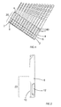
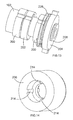
- Figure 1 shows one design of a first section 20 of a cutting tool which is referred to as a hex shank cutting too1.
- the first section 20 of the shank of the hex shank cutting tool comprises two sub sections 2, 4 which have a hexagon cross section and which are separated by a circumferential groove 6 of circular cross section.
- the dimensions of the first section 20 of the hex shank cutting tool are fixed in accordance with a set standard.
- Figure 2 shows another design of a first section 22 of a cutting tool which is referred to as a SDS plus shank cutting tool.
- the first section 22 of the shank of the SDS plus shank cutting tool is circular in cross section and has two grooves 10 located on opposite sides of the shank which extend axially to the rear of the shank and two elongate axial recesses 12 located between the grooves on opposite sides of the shank.
- the dimensions of the first section 22 of the SDS plus shank cutting tool are fixed in accordance with a set standard.
- tool holders are presently required for use with cutting tools having different designs of first sections. This results in the requirement to provide a number of tool holders for each hammer drill in order for the hammer drill to be able to utilize different types of cutting tool. This increases cost as well as requiring the user to swop tool holders when different designs of cutting tool are to be utilized. Furthermore, tool holders of hammer drills are typically incorporated into the design of the hammer drill in an integral manner and therefore cannot be simply be detached and interchanged with another tool holder. This results in a user having to have several hammer drills, each having a different tool holder to hold different designs of cutting tools. Alternatively, if the user only wanted to use a single hammer drill, the user would need to utilize an adaptor to alter the function of the existing tool holder to accommodate the different designs of cutting tool, incurring extra cost and complexity.
- the object of the present invention is to provide a tool holder which is capable of supporting and driving cutting tools which have at least two different designs of first section for connecting the cutting tool to the tool holder.
- the hammer drill disclosed comprises a tubular spindle 100 which is capable of being rotatably driven by an electric motor (not shown) to perform the rotary mode of operation.
- the front end 102 of the spindle 100 comprises a tubular passage 114 which is adapted to receive a first section of a cutting tool and forms part of a tool holder of the hammer drill. Rotation of the spindle 100 results in rotation of a cutting tool when held within the front end 102.
- a ram (not shown) and a beat piece (not shown) are slideably supported within the spindle 100.
- the ram can be reciprocatingly driven within the spindle 100 by a reciprocating piston (not shown) via an air spring and which repetitively strikes the beat piece which beat piece in turn repetitively strikes the end of a cutting tool when held in the tool holder.
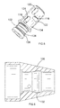
- the tool holder comprises the front end of the spindle 102, a first inner sleeve 104 and a second outer sleeve 106.
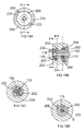
- Figure 4 shows the tubular front end 102 of the spindle 100 with the inner and outer sleeves 104, 106 removed which is formed by a wall of uniform thickness.
- the front end 102 comprises seven circular apertures 108,110, 112 formed through the sides walls of the front end 102.
- the apertures 108, 110, 112 are arranged in two sets of three 108, 112 with the seventh 110 located between the two sets 108, 112.
- Each set 108, 112 of three comprises three apertures located at the same axial position as each other along the spindle and arranged angularly about the longitudinal axis of the front end 102 at 120 degrees relative to each other in a symmetrical fashion.
- the apertures 108, 112 in each set are angularly aligned with the apertures in the other set 108, 110.
- the diameter of each aperture 108, 112 in both sets are all the same as each other.
- the seventh aperture 110 is located axially between the two sets 108, 112 and angularly between two adjacent apertures in each set.
- the diameter of the seventh aperture is slightly larger than that of the six apertures in the two sets 108, 112.
- Six positioning ball bearings 116 are located within the two sets 108, 112 of three apertures, each having the same diameter.
- the diameter of the cross section of each of the six apertures 108, 112 is slightly reduced at the entrance to the six apertures 108, 112 formed in the inner wall of the front end 102 where the apertures 108, 112 meet the tubular passage 114 to prevent the positioning ball bearings 116 from exiting the apertures 108, 112 and entering the tubular passage 114 whilst allowing part of the sides of positioning ball bearings 116 to project into the tubular passage 114 from the apertures.
- the diameter of the support ball bearings 116 is greater than the thickness of the wall of the front end 102 and therefore a part of the sides of the positioning ball bearings 116 either project into the tubular passage 114 or project radially outwardly from the front end 102.
- a seventh locking ball bearing 118 is located within the seventh aperture 110.
- the diameter of the seventh ball bearing 118 is larger than that of the six positioning ball bearings 116.
- the diameter of the cross section of each of the seventh aperture 110 is slightly reduced at the entrance to the seventh aperture 110 formed in the inner wall of the front end 102 where the aperture 110 meets the tubular passage 114 to prevent the ball bearing 118 from exiting the aperture 110 and entering the tubular passage 114 whilst allowing part of the side of the locking ball bearing 118 to project into the tubular passage 114 from the aperture 110.
- the diameter of the ball bearing 118 is greater than the thickness of the front end 102 and therefore a part of the side of the ball bearing 118 either projects into the tubular passage 114 or projects radially outwardly from the front end 102.
- Figure 5 shows the first inner sleeve 104 mounted on the front end 102.
- the fist inner sleeve 104 can axially slide along the front end 102 and rotate around the front end 102.
- the first inner sleeve 104 comprises seven holes 120, 122, 124 formed through the side walls of the first inner sleeve.
- the holes 120, 122, 124 are arranged in two sets of three 120, 124 with the seventh 122 located between the two sets 120, 124.
- Each set 120, 124 of three comprises three holes located at the same axial position as each other along the sleeve 104 and arranged angularly about the axis of the first inner sleeve 104 at 120 degrees relative to each other in a symmetrical fashion.
- the holes 120, 124 in each set are angularly aligned with the holes in the other set 120, 124.
- the shape of the cross section of the six holes 120, 124 is that of an oval with the longer side extending axially along the inner sleeve 104.
- the width of the holes 120, 124 in the lengthwise direction remains substantially constant and is the same as that of the diameter of the apertures 108, 112 for the positioning ball bearings 116 in the front end 102.
- each hole 120, 124 in both sets are all the same as each other.
- the location of the holes 120, 124 on the first inner sleeve 104 correspond to those of the apertures 108, 112 for the positioning ball bearings 116 in the front end 102 of the spindle 102 so that, when the first inner sleeve 104 is in a particular angular position on the front end 102, the holes, 120, 122, 124 and apertures become aligned.
- the seventh hole 122 is located axially between the two sets 120, 124 and angularly between two adjacent holes in each set.
- the shape of the cross section of the seventh hole 122 is that of an oval with the longer side extending circumferentially around the inner sleeve 104.
- the width of the hole 122 in the lengthwise direction remains substantially constant and is slightly larger than that of the diameter of the seventh aperture 110 in the front end 102.
- the second outer sleeve 106 is rigidly mounted onto the first inner sleeve 104.
- a radial groove 132 Formed in the inner wall 130 of the outer sleeve is a radial groove 132 as best seen in Figure 6 .
- the depth of the groove 132 across the width of the groove in an in axial direction of the outer sleeve 106 increases in the forward direction (as shown in Figure 8B ), the shape of the cross section of the width of the grove 132 remaining constant along the length of the groove 132 around the inner wall of the second outer sleeve 106.
- a spring 134 is sandwiched between a shoulder 136 on the spindle 100 and the second inner sleeve 104, biasing the inner and outer sleeves 104, 106 in a forward direction.
- the length of the six oval holes 120, 124 for the positioning balls 116 is such that a part of each of the oval holes 120, 124 remains in alignment with the corresponding aperture 108, 112 over the full range of axial sliding movement of the inner and outer sleeves on the front end 102.
- the size of the seventh hole 122 aligns with the seventh aperture 110 when the inner and outer sleeves 104, 106 at a rearward axial position on the front end 102.
- the length of the seventh hole 122 is such that a part of the seventh hole 122 remains in alignment with the seventh aperture 110 over the full range of angular movement of the inner and outer sleeves 104, 106 on the front end 102.
- the inner and outer sleeves 102 may be rotated to one of two angular positions on the front end 102, a first where the angular position of the inner sleeve 104 and outer sleeve 106 relative to the front end 102 are such that the six holes 120, 124 in the inner sleeve 104 are aligned with the six apertures 108, 112 for the positioning ball bearings 116 and a second where the six holes 120, 124 in the inner sleeve 104 are offset relative to the apertures 108, 112 for the positioning ballbearings 116.
- a part of the sides of the positioning ball bearings 116, 118 can either project from the apertures 108, 112 into the tubular passage 114 or project radially outwardly from the apertures 108, 112 in the front end 102 and into the corresponding holes 120, 124.
- the inner and outer sleeves 104, 106 are biased forwards by the spring 134 to a maximum forward position on the front end 102.
- the sleeves 104, 106 are in their first position with the holes 120, 122, 124 aligned with the apertures 108, 110, 112, it is the rear parts of the oval holes 120, 124 that are in alignment with the apertures 108, 112 for the positioning ball bearings 116 as the sleeves 104, 106 are biased forwards by the spring 134 when the tool holder is unused.
- the inner and outer sleeves 102 may also be axially slid between one of two axial positions on the front end 102, a first rearward axial position of the inner sleeve 104 and outer sleeve 106 relative to the front end 102 where the seventh hole 122 in the inner sleeve 104 is aligned with the seventh aperture 110 of the front end 102 and a second forward position where the seventh hole 122 in the inner sleeve 104 is offset relative to the seventh aperture 110 of the front end 102.
- a part of the side of the locking ball bearing 118 can either project from the aperture 110 into the tubular passage 114 or project radially outwardly from the aperture 110 in the front end 102 and into the seventh hole 122 and groove 132.
- the present embodiment of tool holder can be used to hold cutting tools with two different design of first section, namely a cutting tool with a hex shank and a cutting tool with a SDS plus shank.
- the positioning ball bearings 116 In order for the tool holder to be used with a hex shank, the positioning ball bearings 116 must be in their inner position. When the positioning ball bearings 116 are in their inner position, they provide support to the sides of the shank of the hex shank. If the positioning ball bearings 116 are in an out outer position, they would not provide any support to the sides of the hex shank, allowing too much movement of the cutting tool in a direction perpendicular to its longitudinal axis.
- the inner and out sleeves 104, 106 are rotated on the front end 102 so that they in their second angular position with the six holes 120, 124 of the inner sleeve 104 are offset to the corresponding apertures 108, 112 of the front end 102.
- the side walls of the apertures 108, 112 may be angled slightly to encourage the movement of the positioning ball bearings 116 to their inner position. In this position, a part of the sides of each of the positioning ball bearings 116 projects from the apertures 108, 112 into the tubular passage 114 and are held in this inner position.
- the dimensions of the tool holder are such that when the positioning ball bearings 116 are in this position, they correspond to the outer dimensions of the centre of the flat sides 140 of the hex shank.
- the inner and outer sleeves 104, 106 are slid rearwardly on the front end 102 against the biasing force of the spring 134 so that the seventh hole 122 and groove 132 align with the seventh aperture 110. This allows the locking ball bearing 118 to move outwardly, with part of the locking ball bearing 118 entering the seventh hole 122 and groove 132.
- the first section 20 of the hex shank is then inserted into the tool holder (as shown in Figures 7A to 7D ).
- the positioning ball bearings 116 engage with the centre of the flat sides 140 of the hex shank and guide the movement of the first section 20 inside the tubular passage 114, preventing movement of the hex shank in a direction perpendicular to the longitudinal axis of the hex shank.
- the hex shank is inserted to a depth where the groove 6 of the first section is aligned with the locking ball bearing 118.
- the inner and outer sleeves are then released, allowing the spring 134 to move the sleeves 104, 106 in a forward direction.
- the groove 132 and seventh hole 122 move forward of the seventh aperture 110, causing the locking ball bearing 118 to move to its inner position where it is held by the inner wall of the inner sleeve 104.
- the shape of the groove 132 in the outer sleeve encourages the movement of the locking ball bearing into its inner position.
- the side walls of the seventh aperture 110 may be angled slightly to encourage the movement of the locking ball bearing 116 to its inner position.
- part of the locking ball bearing 118 extends into the tubular passageway 114 and into the groove 6 of the first section 20 of the hex shank. The hex shank is axially locked into the tool holder by locking ball 118 being held in the groove 6 of the first section 20 of the hex shank.
- the positioning ball bearings 116 located against the centre of the flat sides 140 of the two sub sections 2, 4. As the positioning ball bearings 116 are held in this position by the inner sleeve, they are prevented from moving outwardly and therefore cannot pass over the axial ridges formed between adjacent flat faces 140 of the hex shank. Therefore, each positioning ball bearing is locked against the flat side 140 it is engaged with in a circumferential direction. As such, when the tool holder is rotated, the rotary movement of the tool holder is transferred to the hex shank via the positioning ball bearings 116 which are locked against the face of the flat sides 140.
- the first section of the hex shank is released from the tool holder by the inner and outer sleeves 104, 106 being slid rearwardly against the biasing force of the spring 134 to align the groove 132, the seventh hole 122 and the aperture 110.
- the part of locking ball bearing 118 in the tubular passage 114 moves out of the tubular passage 114, disengaging from the groove 6 of the first section 20 of the hex shank, allowing it to be withdrawn from the tool holder.
- the positioning ball bearings 116 In order for the tool holder to be used with a SDS plus shank, the positioning ball bearings 116 must be in their outer position. When the positioning ball bearings 116 are in their outer position, they provide support to the sides of the shank of the SDS plus shank. If the positioning ball bearings 116 are in their inner position, the first section of the SDS plus shank would be prevented from entering the tubular passage 114 of the tool holder.
- the inner and out sleeves are rotated on the front end 102 so that they in their first angular position with the six holes 120, 124 of the inner sleeve 104 are aligned with the corresponding apertures of the front end 102.
- a part of the sides of each of the positioning ball bearings 116 are able to project outwardly from the apertures 108, 112 into the holes 120, 124 of the inner sleeve 104.
- the dimensions of the tool holder are such that when the positioning ball bearings 116 located in their outer position, they correspond to the outer dimensions of the first section of the SDS plus shank
- the inner and outer sleeves 104, 106 are slid rearwardly on the front end 102 against the biasing force of the spring 134 so that the seventh hole 122 and groove 132 align with the seventh aperture 110. This allows the locking ball bearing to move outwardly, with part of the locking ball bearing 118 entering the seventh hole 122 and groove 132.
- the first section 22 of the SDS plus shank is then inserted into the tool holder (as shown in Figures 9A to 9D ).
- the positioning ball bearings 116 engage with the end of the first section 22 of the SDS plus shank and move them to their outer most position. Subsequently, the positioning ball bearings 116 engage with the sides of the first section 22 of the SDS plus shank and guide the movement of the first section 22 inside the tubular passage 114, preventing movement of the SDS plus shank in a direction perpendicular to the longitudinal axis of the SDS plus shank.
- the SDS plus shank is inserted to a depth where one of the elongate axial recesses 12 of the first section 22 is aligned with the locking ball bearing 118.
- the inner and outer sleeves 104, 106 are then released, allowing the spring 134 to move the sleeves 104, 106 in a forward direction.
- the groove 132 and seventh hole 122 move forward of the seventh aperture 110, causing the ball bearing to move to its inner position where it is held by the tapered rear wall 131 inner wall of the inner sleeve 104 (as shown in Figures 10A to 10D ).
- the shape of the groove 132 in the outer sleeve 106 and the tapered rear side wall 131 encourages the movement of the locking ball bearing 118 into its inner position.
- part of the locking ball bearing 118 extends into the tubular passageway 114 and into the elongate axial recess 12 of the first section 22 of the SDS plus shank.
- the SDS plus shank is axially locked into the tool holder by locking ball 118 being held in the axial recess 12 of the first section 22 of the SDS plus shank.
- the SDS plus shank can axially slide over a limited range of movement due to the locking ball bearing 118 sliding along the axial recess 12.
- ribs 150 Formed insides of the tubular passage 114, along the length of the passage 114, are two ribs 150 which are located opposite each other within the tubular passage 114.
- the ribs 150 engage with the grooves 10 in the first section 22.
- Rotary movement of the tool holder is transferred to the first section 22 of the SDS plus shank via the ribs 150 engagement with the grooves 10.
- the height of the ribs 150 is such that they do not interfere with the insertion of a hex shank into the tubular passageway 114 of the tool holder.
- the first section of the SDS plus shank is released from the tool holder by the inner and outer sleeves 104, 106 being slid rearwardly against the biasing force of the spring 134 to align the groove 132, the seventh hole 122 and the aperture 110.
- the part of locking ball bearing 118 in the tubular passage 114 can move out of the tubular passage 114, disengaging from the axial recess 12 of the first section 22 of the SDS plus shank, allowing it to be withdrawn from the tool holder.
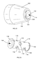
- the second embodiment of the tool holder comprises the front end 102 of the spindle, two positioning sleeves 200, a locking sleeve 202, an end plate 204, and an outer twisting sleeve 206. Where the same features in the second embodiment were present in the first, the same reference numbers have been used.
- Figure 12 shows the tubular front end 102 of the spindle 100 without the sleeves 200, 202, 206 and end plate 204 which is formed by a wall of uniform thickness except along one side at the front where a flat surface 208 has been formed.
- the front end 102 comprises seven circular apertures 108, 110, 112 formed through the sides walls of the front end 102 away from the flat surface 208.
- the apertures 108, 110, 112 are arranged in two sets of three 108, 112 with the seventh 110 located between the two sets 108, 112.
- Each set 108, 112 of three comprises three apertures located at the same axial position as each other along the front end 102 and arranged angularly about the longitudinal axis of the front end 102 at 120 degrees relative to each other in a symmetrical fashion.
- the apertures 108, 112 in each set are angularly aligned with the apertures in the other set 108, 110.
- the diameter of each aperture 108, 112 in both sets are all the same as each other.
- the seventh aperture 110 is located axially between the two sets 108, 112 and angularly between two adjacent apertures in each set. The diameter of the seventh aperture is slightly larger than that of the six apertures in the two sets 108, 112.
- Six positioning ball bearings 116 are located within the two sets 108, 112 of three apertures, each having the same diameter.
- the diameter of the cross section of each of the six apertures 108, 112 is slightly reduced at the entrance to the six apertures 108, 112 formed in the inner wall of the front end 102 where the apertures 108, 112 meet the tubular passage 114 to prevent the positioning ball bearings 116 from exiting the apertures 108, 112 and entering the tubular passage 114 whilst allowing part of the sides of positioning ball bearings 116 to project into the tubular passage 114 from the apertures.
- the diameter of the support ball bearings 116 is greater than the thickness of the wall of the front end 102 and therefore a part of the sides of the positioning ball bearings 116 either project into the tubular passage 114 or project radially outwardly from the front end 102.
- a seventh locking ball bearing 118 is located within the seventh aperture 110.
- the diameter of the seventh ball bearing 118 is larger than that of the six positioning ball bearings 116.
- the diameter of the cross section of each of the seventh aperture 110 is slightly reduced at the entrance to the seventh aperture 110 formed in the inner wall of the front end 102 where the aperture 110 meets the tubular passage 114 to prevent the ball bearing 118 from exiting the aperture 110 and entering the tubular passage 114 whilst allowing part of the side of the locking ball bearing 118 to project into the tubular passage 114 from the aperture 110.
- the diameter of the ball bearing 118 is greater than the thickness of the front end 102 and therefore a part of the side of the ball bearing 118 either projects into the tubular passage 114 or projects radially outwardly from the front end 102.
- two positioning sleeves 200 are rotationally mounted on the front end 102, each of which surrounds one set of the positioning ball bearings 116.
- One locking sleeve 204 is mounted between the two positioning sleeves 200 and surrounds the locking ball bearing 118.
- the end plate 204 is mounted on the end of the front end 102.
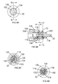
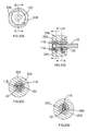
- the end plate 204 (as shown in Figure 15 ) comprises an aperture 210 which has a corresponding cross section in shape to that of the end of the front end 102, the end being inserted into the aperture 210.
- the aperture 210 comprises a corresponding flat surface 212 which engages with the flat surface 208 of the front end 102. This prevents the end plate 204 from rotating around the front end 102 making it rotationally fixed to the front end 102.
- the outer twisting sleeve 206 (as shown in Figure 14 ) is mounted on and rigidly attached to the two positioning sleeves 200 and the locking sleeve 202 by axial ribs 214 formed on the inside of the twisting sleeved 206 locating in and engaging with axial slots 215 formed on the outer periphery to the two positioning sleeves 200 (as shown in Figure16 ) and the locking sleeve 202 (as shown in Figure 17 ). Rotation of the twisting sleeve 206 results in rotation of the two positioning sleeves 200 and the locking sleeve 202 by the same amount.
- the twisting sleeve 206 is prevented from sliding rearwardly by abutting against a shoulder 216 formed on the front end 102 of the spindle 100.
- the twisting sleeve 206 is prevented from sliding forward by the end plate 204. As such the twisting sleeve 206 is prevented from moving axially on the front end 102, which in turn prevents any axial movement of the two positioning sleeves 200 and the locking sleeve 202 on the front end 102.
- a recess 218 is formed in the front end of the twisting sleeve 206 in which the end plate 204 is located.
- the end plate comprises two arms 220, 222 which project radially outwards in opposite directions.
- the edge of the recess 218 comprises two pockets 224, 226 into each of which projects an arm 220, 222.
- the arms 220, 222 and pockets 224, 226 limit the amount of angular movement of the twisting sleeve 206 on the front end 102.
- a spring 228 is attached between the end plate 204 and the twisting sleeve 206 and angularly biases it towards a first angular end position where the arms 220, 222 are located at one end of the pockets 224, 226.
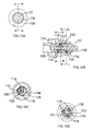
- Figure 16 shows the positioning sleeve 200.
- Formed symmetrically around the internal wall 230 are three identical cam surfaces 232, each of which has three locating positions 234, 236, 238.
- one positioning ball bearing 116 locates against each cam surface 232, the positioning ball bearing 116 engaging with the cam surface at different positions along the cam surface depending on the angular position of the positioning sleeve 200 on the front end 102.
- the positioning ball bearings 116 are located in a different radial positions.
- the spring 228 urges the twisting sleeve towards its first end position which is where the cam surfaces urges the positioning ball bearings 116 to their inner most position.
- Figure 17 shows the locking sleeve 202.
- a cam surface 242 Formed on the internal wall 240 is a cam surface 242 which has three locating positions 244, 246, 248.
- the locking ball bearing 118 locates against the cam surface 242, the locking ball bearing 118 engaging with the cam surface at different positions along the cam surface depending on the angular position of the locking sleeve202 on the front end.
- the locking ball bearing 118 is located at the three locating positions, the locking ball bearing 118 is located in a different radial position.
- the spring 228 urges the twisting sleeve towards its first end position which is where the cam surface 242 urges the locking ball bearing 118 to its inner most position.
- the twisting sleeve 206 is rotated against biasing force of the spring 228 so that each of the arms 220, 222 of the end plate 204 move from one end of the pocket 224, 226 to a second end position at the other end of the pocket 224, 226.
- the cams 232 which are in engagement with the positioning ball bearings 116 moving over the position ball bearings 116 (which are rotationally fixed relative the front end 102 due to being located within the apertures 108, 112) until the ball bearings 116 are capable of locating in a first locating position 234 on the cam 232.
- the first locating position 234 is the position where the ball bearings 116 can locate in their most radially outward position.
- the cam 242 which is in engagement with the locking ball bearing 118 moves over the locking ball bearing 116 (which is rotationally fixed relative the front end 102 due to be located within the seventh aperture 110) until the ball bearing 118 is capable of locating in a first locating position 244 on the cam 242.
- the first locating position 244 is the position where the locking ball bearing 118 can locate in the most radially outward position.
- the twisting sleeve 206 When the twisting sleeve 206 is twisted to its second end position, the first section 20 of the hex shank is inserted into the tubular passage 114 (as shown in Figures 18A to 18D ). As the cams 232, 242 for the positioning ball bearings 116 and the locking ball bearing 118 are located with their first locating position 234, 244 facing the ball bearings 116, 118, the ball bearings 116, 118 can move to their outer most position allowing the first section 20 to pass by. The twisting force applied to twisting sleeve 206 is then removed, allowing the twisting sleeve 206 to rotate due to the biasing force of the spring 228.
- the rotation of the twisting sleeve 206 causes the positioning sleeves 200 and locking sleeve 202 to rotate such that the third locating positions 238, 248 face and engage with the ball bearings 116, 118.
- the ball bearings 116, 118 are urged to the inner most position.
- the positioning ball bearings 116 engage with the flat surfaces 140 of sides of the first section 20 and the locking ball bearing 118 engages with the groove 6 (as shown in Figures 19A to 19D ).
- the positioning ball bearings 116 prevent movement of the first section 20 in a direction perpendicular to the longitudinal axis of the cutting tool.
- the locking ball bearing 118 axially locks the first section 20 within the tubular passage 114. Rotational movement of the tool holder is transferred to the first section 20 via the positioning ball bearings 116 and their engagement with the flat surfaces 140 of the first section 20.
- the twisting sleeve 206 In order to release the first section 20 of the hex shank from the tool holder, the twisting sleeve 206 is rotated against the biasing force of the spring 228 until it is located in its first end position. When the twisting sleeve 206 is in this position, the cams 232, 242 for the positioning ball bearings 116 and the locking ball bearing 118 are located with their first locating position, 234, 244 facing the ball bearings 116, 118. This allows the ball bearings 116, 118 to move to their outer most position allowing the first section 20 to pass by and be removed from the tool holder.
- the twisting sleeve 206 When the twisting sleeve 206 is twisted to its second end position, the first section 22 of the SDS shank is inserted into the tubular passage 114. As the cams 232, 242 for the positioning ball bearings 116 and the locking ball bearing 118 are located with their first locating position 234, 244 facing the ball bearings 116, 118 the ball bearings 116, 118 can move to their outer most position allowing the first section 22 to pass by. The twisting force applied to twisting sleeve 206 is then removed, allowing the twisting sleeve 206 to rotate due to the biasing force of the spring 228.
- the rotation of the twisting sleeve 206 causes the positioning sleeves 200 and locking sleeve 202 to rotate such that a second intermediate locating position 236, 246 of the cams 232, 242 face and engage with the ball bearings 116, 118.
- the positioning ball bearings 116 are urged into engagement with the sides of the first section 22 and the locking ball bearing 118 engages with an axial recess 12.
- the positioning ball bearings 116 prevent movement of the first section 22 in a direction perpendicular to the longitudinal axis of the cutting tool.
- the locking ball bearing 118 axially locks the first section 22 within the tubular passage 114. Rotational movement of the tool holder is transferred to the first section 22 via ribs 150 formed inside of the tubular passage 114 which engage with the grooves 10 in the first section 22.
- the twisting sleeve 206 In order to release the first section 22 of the SDS plus shank from the tool holder, the twisting sleeve 206 is rotated against the biasing force of the spring until it is located in its first end position. When the twisting sleeve 206 is in this position, the cams 232, 242 for the positioning ball bearings 116 and the locking ball bearing 118 are located with their first locating position 234, 244 facing the ball bearings 116, 118. This allows the ball 116, 118 bearings to move to their outer most position allowing the first section 22 to pass them by and be removed from the tool holder.
- the tool holder comprises the front end 102 of the spindle, a first inner sleeve 104 and a second outer sleeve 106.
- Figure 23 shows the tubular front end 102 of the spindle 100 which is formed by a wall of uniform thickness except for a fat surface 300 formed on one side along the length at the front end 102.
- the front end 102 comprises seven circular apertures 108,110, 112 formed through the side walls of the front end 102.
- the apertures 108, 110, 112 are arranged in two sets of three 108, 112 with the seventh 110 located between the two sets 108, 112.
- Each set 108, 112 of three comprises three apertures located at the same axial position as each other along the spindle and arranged angularly about the longitudinal axis of the front end 102 at 120 degrees relative to each other in a symmetrical fashion.
- the apertures 108, 112 in each set are angularly aligned with the apertures in the other set 108, 110.
- the diameter of each aperture 108, 112 in both sets are all the same as each other.
- the seventh aperture 110 is located axially between the two sets 108, 112 and angularly between two adjacent apertures in each set.
- the diameter of the seventh aperture is slightly larger than that of the six apertures in the two sets 108, 112.
- Six positioning ball bearings 116 are located within the two sets 108, 112 of three apertures, each having the same diameter.
- the diameter of the cross section of each of the six apertures 108, 112 is slightly reduced at the entrance to the six apertures 108, 112 formed in the inner wall of the front end 102 where the apertures 108, 112 meet the tubular passage 114 to prevent the positioning ball bearings 116 from exiting the apertures 108, 112 and entering the tubular passage 114 whilst allowing part of the sides of positioning ball bearings 116 to project into the tubular passage 114 from the apertures.
- each of the support ball bearings 116 is greater than the thickness of the wall of the front end 102 and therefore a part of the sides of the positioning ball bearings 116 either project into the tubular passage 114 or project radially outwardly from the front end 102.
- a seventh locking ball bearing 118 is located within the seventh aperture 110.
- the diameter of the seventh ball bearing 118 is larger than that of the six positioning ball bearings 116.
- the diameter of the cross section of each of the seventh aperture 110 is slightly reduced at the entrance to the seventh aperture 110 formed in the inner wall of the front end 102 where the aperture 110 meets the tubular passage 114 to prevent the ball bearing 118 from exiting the aperture 110 and entering the tubular passage 114 whilst allowing part of the side of the locking ball bearing 118 to project into the tubular passage 114 from the aperture 110.
- the diameter of the ball bearing 118 is greater than the thickness of the front end 102 and therefore a part of the side of the ball bearing 118 either projects into the tubular passage 114 or projects radially outwardly from the front end 102.
- Figure 24 shows the first inner sleeve 104 mounted on the front end 102.
- the fist inner sleeve 104 can axially slide along the front end 102.
- the first inner sleeve has a flat inner surface 302 which engages that of the front end 102 of the spindle. The engagement of the flat surfaces 300, 302 prevents the first inner sleeve 104 from rotating around the front end 102.
- the first inner sleeve 104 comprises seven holes 120, 122, 124 formed through the side walls of the first inner sleeve.
- the holes 120, 122 124 are arranged in two sets of three 120, 124 with the seventh 122 located between the two sets 120, 124.
- Each set 120, 124 of three comprises three holes located at the same axial position as each other along the sleeve 104 and arranged angularly about the axis of the first inner sleeve 104 at 120 degrees relative to each other in a symmetrical fashion.
- the holes 120, 124 in each set are angularly aligned with the holes in the other set 120, 124.
- the shape of the cross section of the six holes 120, 124 is that of an oval with the longer side extending axially along the inner sleeve 104.
- the width of the holes 120, 124 in the lengthwise direction remains substantially constant and is that same as that of the diameter of the apertures 108, 112 for the positioning ball bearings 116 in the front end 102.
- each hole 120, 124 in both sets are all the same as each other.
- the location of the holes 120, 124 on the first inner sleeve 104 correspond to those of the apertures 108, 112 for the positioning ball bearings 116 in the front end 102 of the spindle 102 so that, when the first inner sleeve 104 is in a particular axial position on the front end 102, the holes, 120, 122, 124 and apertures 108, 110, 112 become aligned.
- the seventh hole 122 is located axially between the two sets 120, 124 and angularly between two adjacent holes in each set.
- the shape of the cross section of the seventh hole 122 is that of a rectangle with the longer side extending circumferentially around the inner sleeve 104.
- the width of the holes 120, 124 in the lengthwise direction remains substantially constant and is slightly larger than that of the diameter of the seventh aperture 110 in the front end 102.
- the second outer sleeve 106 is rigidly mounted onto the first inner sleeve 104.
- Formed in the inner wall 130 of the outer sleeve is a radial groove 132 as best seen in Figure 25 .
- the depth of the groove 132 across the width of the groove 132 in an in axial direction of the outer sleeve 106 increases in the forward direction (as shown in Figure 26B ), the shape of the cross section of the width of the grove 132 remaining constant along the length of the groove 132 around the inner wall of the second outer sleeve 106.
- the groove 132 aligns with and faces towards the seventh hole 122 in the inner sleeve.
- the width of the groove 132 is greater than the width of the seventh hole 122.
- a spring 134 is sandwiched between a washer 304 which abuts against a shoulder 136 on the spindle 100 and the base of a circular groove 306 formed inside of the outer sleeve 106, biasing the inner and outer sleeves 104, 106 in a forward direction.
- the seventh hole 122 aligns with the seventh aperture 110 when the inner and outer sleeves 104, 106 are at a rearward axial position on the front end 102.
- the inner and outer sleeves 102 can be axially slid between one of two axial end positions on the front end 102, a first rearward axial position where the seventh hole 122 in the inner sleeve 104 is aligned with the seventh aperture 110 of the front end 102 and a second forward position where the seventh hole 122 in the inner sleeve 104 is offset relative to the seventh aperture 110 of the front end 102.
- the inner and outer sleeves 104, 106 are axially slid to the rearward axial end position on the front end 102, the six apertures 108, 112 of the front end 102 and the six holes 120, 124 of the inner sleeve 104 are also aligned.
- the six apertures 108, 112 of the front end 102 and the six holes of the inner sleeve are off set.
- the seventh aperture 1 10 of the front end 102 and the seventh hole 122 of the inner sleeve are off set.
- a part of the side of the ball bearings 116, 118 can either project from the apertures 108, 110, 112 into the tubular passage 114 or project radially outwardly from the apertures 108, 110, 112 in the front end 102 and into the holes 120 122, 124 and groove 132.
- the sleeves 104, 106 When the sleeves 104, 106 are in their forward position, the holes 108, 110, 112 and apertures 120, 122, 124 are offset. When they are off set, the ball bearings 116, 118 are urged inwardly and held in this position, the positioning ball bearings 116 engaging with the flat surfaces 140 of sides of the first section 20 and the locking ball bearing 118 engaging with the groove 6.
- the spring 234 holds the sleeves in their forward position, ensuring the holes 108, 110, 112 and apertures 120, 122 124 are offset and therefore locking the ball bearings 116, 118 in their inner position.
- the positioning ball bearings 116 prevent movement of the first section in a direction perpendicular to the longitudinal axis of the cutting tool.
- the locking ball bearing 118 axially locks the first section 20 within the tubular passage 114. Rotational movement of the tool holder is transferred to the first section via the positioning ball bearings 116 and their engagement with the flat surfaces 140 of the first section 20.
- the inner and outer sleeves are slid rearwardly against the biasing force of the spring until it is located in its rearward end position.
- the apertures and holes are aligned, allowing the ball bearings to move to their outer most position allowing the first section to pass by and be removed from the tool holder.
- the six apertures 108, 112 for the positioning ball bearings 116 and the six corresponding holes 120, 124 remain aligned. As such, they positioning ball bearings 116 can be located in their radially outer position in engagement in the sides of the first section 22 of the shank. However, the seventh aperture 110 and seventh hole 122 become partially offset, urging the locking ball bearing 118 into the axial recess 12 of the first section. However, as the seventh aperture 110 and seventh hole 122 are only partially offset, the locking ball bearing 118 is urged to a lesser depth than when they are totally offset. The locking ball bearing 118 is held in its inner position by the force of the spring 134.
- the positioning ball bearings 116 prevent movement of the first section in a direction perpendicular to the longitudinal axis of the cutting tool.
- the locking ball bearing 118 axially locks the first section within the tubular passage 118 (whilst allowing li ited axial movement as the locking ball bearing 118 can slide within the axial recess 12). Rotational movement of the tool holder is transferred to the first section 22 via ribs 150 formed inside of the tubular passage 114 which engage with the grooves 10 in the first section 22.
- the sleeves 104, 106 are slid back against the biasing force of the spring 134 until it is located in its rearward position.
- the holes 108, 110, 112 and apertures are all aligned, allowing the ball bearings 116, 118 to move to their outer most positions allowing the first section 22 to pass them by and be removed from the tool holder.
- embodiments of the invention can comprise tool holders which are constructed as separate discreet devices capable of being attached to a hammer drill.
- tool holder Whilst the three embodiments of tool holder have been described in relation to holding hex shanked and a SDS plus shanked cutting tools, it will be appreciated that such a design can be utilized on other designs of shank.
Abstract
Description
- The present invention relates to a tool holder for a drill, particularly a hammer drill.
- Hammer drills are power tools that can often operate in three modes of operation. A hammer drill will comprise a tool holder in which a cutting tool, such as a drill bit, can be supported and driven by the hammer drill. The hammer drill can actively drive the cutting tool in three different ways, each being referred to as a mode of operation. The cutting tool can be driven in a hammering mode, a rotary mode and a combined hammer and rotary mode. A hammer drill will typically comprises an electric motor and a transmission mechanism by which the rotary output of the electric motor can either rotationally drive the cutting tool to perform the rotary mode or repetitively strike the cutting tool to perform the hammer mode or rotationally drive and repetitively strike the cutting tool to perform the combined hammer and rotary mode.
-
EP1157788 discloses a typical hammer drill. - Cutting tools for hammer drills typically comprise two sections: a first section which connects to a tool holder of a hammer drill and a second section which performs the cutting task of the cutting tool when driven by the hammer drill. The design of first section can vary.
-
Figure 1 shows one design of afirst section 20 of a cutting tool which is referred to as a hex shank cutting too1. Thefirst section 20 of the shank of the hex shank cutting tool comprises twosub sections circumferential groove 6 of circular cross section. The dimensions of thefirst section 20 of the hex shank cutting tool are fixed in accordance with a set standard. -
Figure 2 shows another design of afirst section 22 of a cutting tool which is referred to as a SDS plus shank cutting tool. Thefirst section 22 of the shank of the SDS plus shank cutting tool is circular in cross section and has twogrooves 10 located on opposite sides of the shank which extend axially to the rear of the shank and two elongateaxial recesses 12 located between the grooves on opposite sides of the shank. The dimensions of thefirst section 22 of the SDS plus shank cutting tool are fixed in accordance with a set standard. - Different types of tool holders are presently required for use with cutting tools having different designs of first sections. This results in the requirement to provide a number of tool holders for each hammer drill in order for the hammer drill to be able to utilize different types of cutting tool. This increases cost as well as requiring the user to swop tool holders when different designs of cutting tool are to be utilized. Furthermore, tool holders of hammer drills are typically incorporated into the design of the hammer drill in an integral manner and therefore cannot be simply be detached and interchanged with another tool holder. This results in a user having to have several hammer drills, each having a different tool holder to hold different designs of cutting tools. Alternatively, if the user only wanted to use a single hammer drill, the user would need to utilize an adaptor to alter the function of the existing tool holder to accommodate the different designs of cutting tool, incurring extra cost and complexity.
- The object of the present invention is to provide a tool holder which is capable of supporting and driving cutting tools which have at least two different designs of first section for connecting the cutting tool to the tool holder.
- Accordingly, there is provided a tool holder in accordance with claim 1.
- Three embodiments of the present invention will now be described with reference to accompanying drawings of which:
-
Figure 1 shows a hex shank cutting tool; -
Figure 2 shows a SDS plus cutting tool; -
Figure 3 shows a side view of the first embodiment of the tool holder; -
Figure 4 shows the front end of the spindle of a hammer drill with the positioning ball bearings and locking ball bearing in their respective apertures; -
Figure 5 shows the first inner sleeve mounted on the front end of the spindle together with the biasing spring; -
Figure 6 shows the inside view of the second outer sleeve with the radial groove; -
Figure 7A shows a side view of the tool holder with the first section of a hex shank cutting tool being inserted into the tool holder with the second outer sleeve in the released position; -
Figure 7B shows a cross section of tool holder ofFigure 7A in the direction of Arrows A; -
Figure 7C shows a cross section of tool holder ofFigure 7A in the direction of Arrows B through the front positioning ball bearings; -
Figure 7D shows a cross section of tool holder ofFigure 7A in the direction of Arrows C through the locking ball bearing; -
Figure 8A shows a side view of the tool holder with the first section of a hex shank cutting tool located within the tool holder with the second outer sleeve in the locked position; -
Figure 8B shows a cross section of tool holder ofFigure 8A in the direction of Arrows D; -
Figure 8C shows a cross section of tool holder ofFigure 8A in the direction of Arrows E through the front positioning ball bearings; -
Figure 8D shows a cross section of tool holder ofFigure 8A in the direction of Arrows F through the locking ball bearing; -
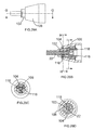
Figure 9A shows a front view of the tool holder with the first section of a SDS plus shank cutting tool being inserted within the tool holder with the second outer sleeve in the released position; -
Figure 9B shows a cross section of tool holder ofFigure 9A in the direction of Arrows G; -
Figure 9C shows a cross section of tool holder ofFigure 9B in the direction of Arrows H through the locking ball bearing; -
Figure 9D shows a cross section of tool holder ofFigure 9B in the direction of Arrows I through the front positioning ball bearings; -
Figure 10A shows a front view of the tool holder with the first section of a SDS plus shank cutting tool located within the tool holder with the second outer sleeve in the locked position; -
Figure 10B shows a cross section of tool holder ofFigure 10A in the direction of Arrows J; -
Figure 10C shows a cross section of tool holder ofFigure 10B in the direction of Arrows K through the locking ball bearing; -
Figure 10D shows a cross section of tool holder ofFigure 10B in the direction of Arrows L through the front positioning ball bearings; -
Figure 11 shows a side view of the second embodiment of the tool holder; -
Figure 12 shows the front end of the spindle of a hammer drill with the positioning ball bearings and locking ball bearing in their respective apertures; -
Figure 13 shows the two positioning sleeves, the locking sleeve, and the end plate mounted on the front end of the spindle together with a biasing spring; -
Figure 14 shows the inside view of the twisting sleeve; -
Figure 15 shows a perspective view of the end plate; -
Figure 16 shows a perspective view of the positioning sleeve; -
Figure 17 shows a perspective view of the locking sleeve; -
Figure 18A shows a front view of the tool holder with the first section of a hex shank cutting tool being inserted into the tool holder with the twisting sleeve in the released position; -
Figure 18B shows a cross section of tool holder ofFigure 18A in the direction of Arrows A; -
Figure 18C shows a cross section of tool holder ofFigure 18B in the direction of Arrows B through the locking ball bearing; -
Figure 18D shows a cross section of tool holder ofFigure 18B the direction of Arrows C through the front positioning ball bearings; -
Figure 19A shows a front view of the tool holder with the first section of a hex shank cutting tool located within the tool holder with the twisting sleeve in the locked position; -
Figure 19B shows a cross section of tool holder ofFigure 19A in the direction of Arrows D; -
Figure 19C shows a cross section of tool holder ofFigure 19B in the direction of Arrows E through the front positioning ball bearings; -
Figure 19D shows a cross section of tool holder ofFigure 19B in the direction of Arrows F through the locking ball bearing; -
Figure 20A shows a front view of the tool holder with the first section of a SDS plus shank cutting tool being inserted within the tool holder with the twisting sleeve in the released position; -
Figure 20B shows a cross section of tool holder ofFigure 20A in the direction of Arrows G; -
Figure 20C shows a cross section of tool holder ofFigure 20B in the direction of Arrows H through the front positioning ball bearings; -
Figure 20D shows a cross section of tool holder ofFigure 20B in the direction of Arrows I through the locking ball bearing; -
Figure 21A shows a front view of the tool holder with the first section of a SDS plus shank cutting tool located within the tool holder with the twisting sleeve in the locked position; -
Figure 21B shows a cross section of tool holder ofFigure 21A in the direction of Arrows J; -
Figure 21C shows a cross section of tool holder ofFigure 21B in the direction of Arrows K through the front positioning ball bearings; -
Figure 21D shows a cross section of tool holder ofFigure 21B in the direction of Arrows L through the locking ball bearing; -
Figure 22 shows a side view of the third embodiment of the tool holder; -
Figure 23 shows the front end of the spindle of a hammer drill with the positioning ball bearings and locking ball bearing in their respective apertures; -
Figure 24 shows the first inner sleeve mounted on the front end of the spindle together with the biasing spring and support washer; -
Figure25 shows the inside view of the second outer sleeve with the radial groove; -
Figure 26A shows a side view of the tool holder with the first section of a hex shank cutting tool being inserted into the tool holder with the second outer sleeve in the released position; -
Figure 26B shows a cross section of tool holder ofFigure 26A in the direction of Arrows A; -
Figure 26C shows a cross section of tool holder ofFigure 26B in the direction of Arrows B through the front positioning ball bearings; -
Figure 26D shows a cross section of tool holder ofFigure 26B in the direction of Arrows C through the locking ball bearing; -
Figure 27A shows a side view of the tool holder with the first section of a hex shank cutting tool located within the tool holder with the second outer sleeve in the locked position; -
Figure 27B shows a cross section of tool holder ofFigure 27A in the direction of Arrows D; -
Figure 27C shows a cross section of tool holder ofFigure 27B in the direction of Arrows E through the front positioning ball bearings; -
Figure 27D shows a cross section of tool holder ofFigure 27B in the direction of Arrows F through the locking ball bearing; -
Figure 28A shows a side view of the tool holder with the first section of a SDS plus shank cutting tool being inserted within the tool holder with the second outer sleeve in the released position; -
Figure 28B shows a cross section of tool holder ofFigure 28A in the direction of Arrows G; -
Figure 28C shows a cross section of tool holder ofFigure 28B in the direction of Arrows H through the front positioning ball bearings; -
Figure 28D shows a cross section of tool holder ofFigure 28B in the direction of Arrows I through the locking ball bearing; -
Figure 29A shows a side view of the tool holder with the first section of a SDS plus shank cutting tool located within the tool holder with the second outer sleeve in the locked position; -
Figure 29B shows a cross section of tool holder ofFigure 29A in the direction of Arrows J; -
Figure 29C shows a cross section of tool holder ofFigure 29B in the direction of Arrows K through the front positioning ball bearings; and -
Figure 29D shows a cross section of tool holder ofFigure 29B in the direction of Arrows L through the locking ball bearing. - The hammer drill disclosed comprises a
tubular spindle 100 which is capable of being rotatably driven by an electric motor (not shown) to perform the rotary mode of operation. Thefront end 102 of thespindle 100 comprises atubular passage 114 which is adapted to receive a first section of a cutting tool and forms part of a tool holder of the hammer drill. Rotation of thespindle 100 results in rotation of a cutting tool when held within thefront end 102. A ram (not shown) and a beat piece (not shown) are slideably supported within thespindle 100. The ram can be reciprocatingly driven within thespindle 100 by a reciprocating piston (not shown) via an air spring and which repetitively strikes the beat piece which beat piece in turn repetitively strikes the end of a cutting tool when held in the tool holder. - The first embodiment of the tool holder will now be described with reference to
Figures 3 to 10 . - The tool holder comprises the front end of the
spindle 102, a firstinner sleeve 104 and a secondouter sleeve 106. -
Figure 4 shows the tubularfront end 102 of thespindle 100 with the inner andouter sleeves front end 102 comprises seven circular apertures 108,110, 112 formed through the sides walls of thefront end 102. Theapertures sets set front end 102 at 120 degrees relative to each other in a symmetrical fashion. Theapertures other set aperture seventh aperture 110 is located axially between the twosets sets - Six
positioning ball bearings 116 are located within the twosets apertures apertures front end 102 where theapertures tubular passage 114 to prevent thepositioning ball bearings 116 from exiting theapertures tubular passage 114 whilst allowing part of the sides ofpositioning ball bearings 116 to project into thetubular passage 114 from the apertures. The diameter of thesupport ball bearings 116 is greater than the thickness of the wall of thefront end 102 and therefore a part of the sides of thepositioning ball bearings 116 either project into thetubular passage 114 or project radially outwardly from thefront end 102. - A seventh
locking ball bearing 118 is located within theseventh aperture 110. The diameter of theseventh ball bearing 118 is larger than that of the sixpositioning ball bearings 116. The diameter of the cross section of each of theseventh aperture 110 is slightly reduced at the entrance to theseventh aperture 110 formed in the inner wall of thefront end 102 where theaperture 110 meets thetubular passage 114 to prevent theball bearing 118 from exiting theaperture 110 and entering thetubular passage 114 whilst allowing part of the side of the lockingball bearing 118 to project into thetubular passage 114 from theaperture 110. The diameter of theball bearing 118 is greater than the thickness of thefront end 102 and therefore a part of the side of theball bearing 118 either projects into thetubular passage 114 or projects radially outwardly from thefront end 102. -
Figure 5 shows the firstinner sleeve 104 mounted on thefront end 102. The fistinner sleeve 104 can axially slide along thefront end 102 and rotate around thefront end 102. - The first
inner sleeve 104 comprises sevenholes holes sets - Each
set sleeve 104 and arranged angularly about the axis of the firstinner sleeve 104 at 120 degrees relative to each other in a symmetrical fashion. Theholes other set holes inner sleeve 104. The width of theholes apertures positioning ball bearings 116 in thefront end 102. The dimensions of eachhole holes inner sleeve 104 correspond to those of theapertures positioning ball bearings 116 in thefront end 102 of thespindle 102 so that, when the firstinner sleeve 104 is in a particular angular position on thefront end 102, the holes, 120, 122, 124 and apertures become aligned. - The
seventh hole 122 is located axially between the twosets seventh hole 122 is that of an oval with the longer side extending circumferentially around theinner sleeve 104. The width of thehole 122 in the lengthwise direction remains substantially constant and is slightly larger than that of the diameter of theseventh aperture 110 in thefront end 102. - The second
outer sleeve 106 is rigidly mounted onto the firstinner sleeve 104. Formed in the inner wall 130 of the outer sleeve is aradial groove 132 as best seen inFigure 6 . The depth of thegroove 132 across the width of the groove in an in axial direction of theouter sleeve 106 increases in the forward direction (as shown inFigure 8B ), the shape of the cross section of the width of thegrove 132 remaining constant along the length of thegroove 132 around the inner wall of the secondouter sleeve 106. When the secondouter sleeve 106 is mounted on the firstinner sleeve 104, thegroove 132 aligns with and faces towards theseventh hole 122 in the inner sleeve. The width of the groove is larger than the width of theseventh hole 122. - A
spring 134 is sandwiched between ashoulder 136 on thespindle 100 and the secondinner sleeve 104, biasing the inner andouter sleeves - When the six
apertures positioning ball bearings 116 and corresponding holes, 120, 122, 124 are in angular alignment due to the angular position of the inner andouter sleeves front end 102, the length of the sixoval holes positioning balls 116 is such that a part of each of theoval holes aperture front end 102. - The size of the
seventh hole 122 aligns with theseventh aperture 110 when the inner andouter sleeves front end 102. When theseventh aperture 110 andseventh hole 122 are in axial alignment due to the rear axial position of the inner andouter sleeves front end 102, the length of theseventh hole 122 is such that a part of theseventh hole 122 remains in alignment with theseventh aperture 110 over the full range of angular movement of the inner andouter sleeves front end 102. - The inner and
outer sleeves 102 may be rotated to one of two angular positions on thefront end 102, a first where the angular position of theinner sleeve 104 andouter sleeve 106 relative to thefront end 102 are such that the sixholes inner sleeve 104 are aligned with the sixapertures positioning ball bearings 116 and a second where the sixholes inner sleeve 104 are offset relative to theapertures positioning ballbearings 116. When the sixholes apertures sleeves positioning ball bearings apertures tubular passage 114 or project radially outwardly from theapertures front end 102 and into the correspondingholes oval holes apertures positioning ball bearings 116, when thesleeves positioning ball bearings apertures tubular passage 114 as they are prevented from projecting radially outwardly from theapertures front end 102 by the inner wall of theinner sleeve 104, the inner wall of theinner sleeve 104 holding thepositioning ball bearings 116 in this inner position. - When the tool holder is unused prior to the insertion of a cutting tool, the inner and
outer sleeves spring 134 to a maximum forward position on thefront end 102. When thesleeves holes apertures oval holes apertures positioning ball bearings 116 as thesleeves spring 134 when the tool holder is unused. - The inner and
outer sleeves 102 may also be axially slid between one of two axial positions on thefront end 102, a first rearward axial position of theinner sleeve 104 andouter sleeve 106 relative to thefront end 102 where theseventh hole 122 in theinner sleeve 104 is aligned with theseventh aperture 110 of thefront end 102 and a second forward position where theseventh hole 122 in theinner sleeve 104 is offset relative to theseventh aperture 110 of thefront end 102. When all theseventh hole 122 is aligned with theseventh aperture 110, when thesleeves ball bearing 118 can either project from theaperture 110 into thetubular passage 114 or project radially outwardly from theaperture 110 in thefront end 102 and into theseventh hole 122 andgroove 132. When theseventh hole 122 is offset relative theseventh aperture 112, when thesleeves seventh aperture 110 into thetubular passage 114 as it is prevented from projecting radially outwardly from theaperture 110 in thefront end 102 by the inner wall of theinner sleeve 104, the inner wall of theinner sleeve 104 holding the lockingball bearing 118 in this inner position. - The present embodiment of tool holder can be used to hold cutting tools with two different design of first section, namely a cutting tool with a hex shank and a cutting tool with a SDS plus shank.
- The use of the first embodiment of the tool holder with a hex shank cutting tool will now be described with reference to
Figures 7 and8 . - In order for the tool holder to be used with a hex shank, the
positioning ball bearings 116 must be in their inner position. When thepositioning ball bearings 116 are in their inner position, they provide support to the sides of the shank of the hex shank. If thepositioning ball bearings 116 are in an out outer position, they would not provide any support to the sides of the hex shank, allowing too much movement of the cutting tool in a direction perpendicular to its longitudinal axis. - Firstly, the inner and out
sleeves front end 102 so that they in their second angular position with the sixholes inner sleeve 104 are offset to the correspondingapertures front end 102. This results in thepositioning ball bearings 116 being moved to their inward position inside of theinner sleeve 104 as best seen inFigures 7B and 7C . The side walls of theapertures positioning ball bearings 116 to their inner position. In this position, a part of the sides of each of thepositioning ball bearings 116 projects from theapertures tubular passage 114 and are held in this inner position. The dimensions of the tool holder are such that when thepositioning ball bearings 116 are in this position, they correspond to the outer dimensions of the centre of theflat sides 140 of the hex shank. - Secondly the inner and
outer sleeves front end 102 against the biasing force of thespring 134 so that theseventh hole 122 and groove 132 align with theseventh aperture 110. This allows the lockingball bearing 118 to move outwardly, with part of the lockingball bearing 118 entering theseventh hole 122 andgroove 132. - The
first section 20 of the hex shank is then inserted into the tool holder (as shown inFigures 7A to 7D ). Thepositioning ball bearings 116 engage with the centre of theflat sides 140 of the hex shank and guide the movement of thefirst section 20 inside thetubular passage 114, preventing movement of the hex shank in a direction perpendicular to the longitudinal axis of the hex shank. The hex shank is inserted to a depth where thegroove 6 of the first section is aligned with the lockingball bearing 118. The inner and outer sleeves are then released, allowing thespring 134 to move thesleeves sleeves groove 132 andseventh hole 122 move forward of theseventh aperture 110, causing the lockingball bearing 118 to move to its inner position where it is held by the inner wall of theinner sleeve 104. The shape of thegroove 132 in the outer sleeve encourages the movement of the locking ball bearing into its inner position. The side walls of theseventh aperture 110 may be angled slightly to encourage the movement of the lockingball bearing 116 to its inner position. In its inner position (as shown inFigures 8A to 8D ), part of the lockingball bearing 118 extends into thetubular passageway 114 and into thegroove 6 of thefirst section 20 of the hex shank. The hex shank is axially locked into the tool holder by lockingball 118 being held in thegroove 6 of thefirst section 20 of the hex shank. - The
positioning ball bearings 116 located against the centre of theflat sides 140 of the twosub sections positioning ball bearings 116 are held in this position by the inner sleeve, they are prevented from moving outwardly and therefore cannot pass over the axial ridges formed between adjacentflat faces 140 of the hex shank. Therefore, each positioning ball bearing is locked against theflat side 140 it is engaged with in a circumferential direction. As such, when the tool holder is rotated, the rotary movement of the tool holder is transferred to the hex shank via thepositioning ball bearings 116 which are locked against the face of theflat sides 140. - The first section of the hex shank is released from the tool holder by the inner and
outer sleeves spring 134 to align thegroove 132, theseventh hole 122 and theaperture 110. This allows part of the thelocking ball bearing 118 to move outwardly from the seventh aperture into theseventh hole 122 andgroove 132. As such, the part of lockingball bearing 118 in thetubular passage 114 moves out of thetubular passage 114, disengaging from thegroove 6 of thefirst section 20 of the hex shank, allowing it to be withdrawn from the tool holder. - The use of the first embodiment of the tool holder with a SDS plus shank cutting tool will now be described with reference to
Figures 9 and10 . - In order for the tool holder to be used with a SDS plus shank, the
positioning ball bearings 116 must be in their outer position. When thepositioning ball bearings 116 are in their outer position, they provide support to the sides of the shank of the SDS plus shank. If thepositioning ball bearings 116 are in their inner position, the first section of the SDS plus shank would be prevented from entering thetubular passage 114 of the tool holder. - Firstly, the inner and out sleeves are rotated on the
front end 102 so that they in their first angular position with the sixholes inner sleeve 104 are aligned with the corresponding apertures of thefront end 102. This results in thepositioning ball bearings 116 being able to move to their outer position inside of theapertures inner sleeve 104 as best seen inFigure 9D . In this position, a part of the sides of each of thepositioning ball bearings 116 are able to project outwardly from theapertures holes inner sleeve 104. The dimensions of the tool holder are such that when thepositioning ball bearings 116 located in their outer position, they correspond to the outer dimensions of the first section of the SDS plus shank - Secondly the inner and
outer sleeves front end 102 against the biasing force of thespring 134 so that theseventh hole 122 and groove 132 align with theseventh aperture 110. This allows the locking ball bearing to move outwardly, with part of the lockingball bearing 118 entering theseventh hole 122 andgroove 132. - The
first section 22 of the SDS plus shank is then inserted into the tool holder (as shown inFigures 9A to 9D ). Thepositioning ball bearings 116 engage with the end of thefirst section 22 of the SDS plus shank and move them to their outer most position. Subsequently, thepositioning ball bearings 116 engage with the sides of thefirst section 22 of the SDS plus shank and guide the movement of thefirst section 22 inside thetubular passage 114, preventing movement of the SDS plus shank in a direction perpendicular to the longitudinal axis of the SDS plus shank. The SDS plus shank is inserted to a depth where one of the elongateaxial recesses 12 of thefirst section 22 is aligned with the lockingball bearing 118. The inner andouter sleeves spring 134 to move thesleeves sleeves groove 132 andseventh hole 122 move forward of theseventh aperture 110, causing the ball bearing to move to its inner position where it is held by the taperedrear wall 131 inner wall of the inner sleeve 104 (as shown inFigures 10A to 10D ). The shape of thegroove 132 in theouter sleeve 106 and the taperedrear side wall 131 encourages the movement of the lockingball bearing 118 into its inner position. In its inner position, part of the lockingball bearing 118 extends into thetubular passageway 114 and into the elongateaxial recess 12 of thefirst section 22 of the SDS plus shank. The SDS plus shank is axially locked into the tool holder by lockingball 118 being held in theaxial recess 12 of thefirst section 22 of the SDS plus shank. The SDS plus shank can axially slide over a limited range of movement due to thelocking ball bearing 118 sliding along theaxial recess 12. - Formed insides of the
tubular passage 114, along the length of thepassage 114, are tworibs 150 which are located opposite each other within thetubular passage 114. Theribs 150 engage with thegrooves 10 in thefirst section 22. Rotary movement of the tool holder is transferred to thefirst section 22 of the SDS plus shank via theribs 150 engagement with thegrooves 10. The height of theribs 150 is such that they do not interfere with the insertion of a hex shank into thetubular passageway 114 of the tool holder. - The first section of the SDS plus shank is released from the tool holder by the inner and
outer sleeves spring 134 to align thegroove 132, theseventh hole 122 and theaperture 110. This allows part of the lockingball bearing 118 to move outwardly from the seventh aperture into theseventh hole 122 andgroove 132. As such, the part of lockingball bearing 118 in thetubular passage 114 can move out of thetubular passage 114, disengaging from theaxial recess 12 of thefirst section 22 of the SDS plus shank, allowing it to be withdrawn from the tool holder. - The second embodiment of the tool holder will now be described with reference to
Figures 11 to 21 . - The second embodiment of the tool holder comprises the
front end 102 of the spindle, two positioningsleeves 200, a lockingsleeve 202, anend plate 204, and anouter twisting sleeve 206. Where the same features in the second embodiment were present in the first, the same reference numbers have been used. -
Figure 12 shows the tubularfront end 102 of thespindle 100 without thesleeves end plate 204 which is formed by a wall of uniform thickness except along one side at the front where aflat surface 208 has been formed. Thefront end 102 comprises sevencircular apertures front end 102 away from theflat surface 208. Theapertures sets set front end 102 and arranged angularly about the longitudinal axis of thefront end 102 at 120 degrees relative to each other in a symmetrical fashion. Theapertures other set 108, 110.The diameter of eachaperture seventh aperture 110 is located axially between the twosets sets - Six
positioning ball bearings 116 are located within the twosets apertures apertures front end 102 where theapertures tubular passage 114 to prevent thepositioning ball bearings 116 from exiting theapertures tubular passage 114 whilst allowing part of the sides ofpositioning ball bearings 116 to project into thetubular passage 114 from the apertures. The diameter of thesupport ball bearings 116 is greater than the thickness of the wall of thefront end 102 and therefore a part of the sides of thepositioning ball bearings 116 either project into thetubular passage 114 or project radially outwardly from thefront end 102. - A seventh
locking ball bearing 118 is located within theseventh aperture 110. The diameter of theseventh ball bearing 118 is larger than that of the sixpositioning ball bearings 116. The diameter of the cross section of each of theseventh aperture 110 is slightly reduced at the entrance to theseventh aperture 110 formed in the inner wall of thefront end 102 where theaperture 110 meets thetubular passage 114 to prevent theball bearing 118 from exiting theaperture 110 and entering thetubular passage 114 whilst allowing part of the side of the lockingball bearing 118 to project into thetubular passage 114 from theaperture 110. The diameter of theball bearing 118 is greater than the thickness of thefront end 102 and therefore a part of the side of theball bearing 118 either projects into thetubular passage 114 or projects radially outwardly from thefront end 102. - As best seen in
Figure 13 , two positioningsleeves 200 are rotationally mounted on thefront end 102, each of which surrounds one set of thepositioning ball bearings 116. Onelocking sleeve 204 is mounted between the two positioningsleeves 200 and surrounds the lockingball bearing 118. Theend plate 204 is mounted on the end of thefront end 102. The end plate 204 (as shown inFigure 15 ) comprises anaperture 210 which has a corresponding cross section in shape to that of the end of thefront end 102, the end being inserted into theaperture 210. Theaperture 210 comprises a correspondingflat surface 212 which engages with theflat surface 208 of thefront end 102. This prevents theend plate 204 from rotating around thefront end 102 making it rotationally fixed to thefront end 102. - The outer twisting sleeve 206 (as shown in
Figure 14 ) is mounted on and rigidly attached to the two positioningsleeves 200 and the lockingsleeve 202 byaxial ribs 214 formed on the inside of the twisting sleeved 206 locating in and engaging withaxial slots 215 formed on the outer periphery to the two positioning sleeves 200 (as shown inFigure16 ) and the locking sleeve 202 (as shown inFigure 17 ). Rotation of the twistingsleeve 206 results in rotation of the two positioningsleeves 200 and the lockingsleeve 202 by the same amount. The twistingsleeve 206 is prevented from sliding rearwardly by abutting against ashoulder 216 formed on thefront end 102 of thespindle 100. The twistingsleeve 206 is prevented from sliding forward by theend plate 204. As such thetwisting sleeve 206 is prevented from moving axially on thefront end 102, which in turn prevents any axial movement of the two positioningsleeves 200 and the lockingsleeve 202 on thefront end 102. - A
recess 218 is formed in the front end of the twistingsleeve 206 in which theend plate 204 is located. The end plate comprises twoarms recess 218 comprises twopockets arm sleeve 206 is rotated aboutfront end 102 and theend plate 204, thearms pockets pockets arms pockets sleeve 206 on thefront end 102. Aspring 228 is attached between theend plate 204 and the twistingsleeve 206 and angularly biases it towards a first angular end position where thearms pockets -
Figure 16 shows thepositioning sleeve 200. Formed symmetrically around theinternal wall 230 are three identical cam surfaces 232, each of which has three locatingpositions positioning sleeve 200 is mounted on thefront end 12, onepositioning ball bearing 116 locates against eachcam surface 232, thepositioning ball bearing 116 engaging with the cam surface at different positions along the cam surface depending on the angular position of thepositioning sleeve 200 on thefront end 102. When eachball bearings 116 is located at the three locatingpositions positioning ball bearings 116 are located in a different radial positions. Thespring 228 urges the twisting sleeve towards its first end position which is where the cam surfaces urges thepositioning ball bearings 116 to their inner most position. -
Figure 17 shows the lockingsleeve 202. Formed on theinternal wall 240 is acam surface 242 which has three locatingpositions sleeve 200 is mounted on thefront end 12, the lockingball bearing 118 locates against thecam surface 242, the lockingball bearing 118 engaging with the cam surface at different positions along the cam surface depending on the angular position of the locking sleeve202 on the front end. When the lockingball bearing 118 is located at the three locating positions, the lockingball bearing 118 is located in a different radial position. Thespring 228 urges the twisting sleeve towards its first end position which is where thecam surface 242 urges the lockingball bearing 118 to its inner most position. - In order to insert a cutting tool into the tool holder, the twisting
sleeve 206 is rotated against biasing force of thespring 228 so that each of thearms end plate 204 move from one end of thepocket pocket cams 232 which are in engagement with thepositioning ball bearings 116 moving over the position ball bearings 116 (which are rotationally fixed relative thefront end 102 due to being located within theapertures 108, 112) until theball bearings 116 are capable of locating in afirst locating position 234 on thecam 232. Thefirst locating position 234 is the position where theball bearings 116 can locate in their most radially outward position. Similarly, when the twistingsleeve 106 is in the second end position, thecam 242 which is in engagement with the lockingball bearing 118 moves over the locking ball bearing 116 (which is rotationally fixed relative thefront end 102 due to be located within the seventh aperture 110) until theball bearing 118 is capable of locating in afirst locating position 244 on thecam 242. Thefirst locating position 244 is the position where the lockingball bearing 118 can locate in the most radially outward position. When thepositioning ball bearings 116 and lockingball bearing 118 are in these positions, first section of either a hex shank cutting tool or a SDS plus cutting tool can be inserted into thetubular passageway 114. - The insertion of a first section of the hex shank cutting tool will now be described with reference to
Figures 18 and19 . - When the twisting
sleeve 206 is twisted to its second end position, thefirst section 20 of the hex shank is inserted into the tubular passage 114 (as shown inFigures 18A to 18D ). As thecams positioning ball bearings 116 and the lockingball bearing 118 are located with theirfirst locating position ball bearings ball bearings first section 20 to pass by. The twisting force applied to twistingsleeve 206 is then removed, allowing the twistingsleeve 206 to rotate due to the biasing force of thespring 228. The rotation of the twistingsleeve 206 causes thepositioning sleeves 200 and lockingsleeve 202 to rotate such that the third locating positions 238, 248 face and engage with theball bearings ball bearings 116, 1118, theball bearings positioning ball bearings 116 engage with theflat surfaces 140 of sides of thefirst section 20 and the lockingball bearing 118 engages with the groove 6 (as shown inFigures 19A to 19D ). Thepositioning ball bearings 116 prevent movement of thefirst section 20 in a direction perpendicular to the longitudinal axis of the cutting tool. The lockingball bearing 118 axially locks thefirst section 20 within thetubular passage 114. Rotational movement of the tool holder is transferred to thefirst section 20 via thepositioning ball bearings 116 and their engagement with theflat surfaces 140 of thefirst section 20. - In order to release the
first section 20 of the hex shank from the tool holder, the twistingsleeve 206 is rotated against the biasing force of thespring 228 until it is located in its first end position. When the twistingsleeve 206 is in this position, thecams positioning ball bearings 116 and the lockingball bearing 118 are located with their first locating position, 234, 244 facing theball bearings ball bearings first section 20 to pass by and be removed from the tool holder. - The insertion of a first section of the SDS plus shank cutting tool will now be described.
- When the twisting
sleeve 206 is twisted to its second end position, thefirst section 22 of the SDS shank is inserted into thetubular passage 114. As thecams positioning ball bearings 116 and the lockingball bearing 118 are located with theirfirst locating position ball bearings ball bearings first section 22 to pass by. The twisting force applied to twistingsleeve 206 is then removed, allowing the twistingsleeve 206 to rotate due to the biasing force of thespring 228. The rotation of the twistingsleeve 206 causes thepositioning sleeves 200 and lockingsleeve 202 to rotate such that a secondintermediate locating position cams ball bearings ball bearings positioning ball bearings 116 are urged into engagement with the sides of thefirst section 22 and the lockingball bearing 118 engages with anaxial recess 12. Thepositioning ball bearings 116 prevent movement of thefirst section 22 in a direction perpendicular to the longitudinal axis of the cutting tool. The lockingball bearing 118 axially locks thefirst section 22 within thetubular passage 114. Rotational movement of the tool holder is transferred to thefirst section 22 viaribs 150 formed inside of thetubular passage 114 which engage with thegrooves 10 in thefirst section 22. - In order to release the
first section 22 of the SDS plus shank from the tool holder, the twistingsleeve 206 is rotated against the biasing force of the spring until it is located in its first end position. When the twistingsleeve 206 is in this position, thecams positioning ball bearings 116 and the lockingball bearing 118 are located with theirfirst locating position ball bearings ball first section 22 to pass them by and be removed from the tool holder. - The third embodiment of the tool holder will now be described with reference to
Figures 22 to 29 . Where the same features are present in third embodiment, which were present in the first, the same reference numbers have been used. - The tool holder comprises the
front end 102 of the spindle, a firstinner sleeve 104 and a secondouter sleeve 106. -
Figure 23 shows the tubularfront end 102 of thespindle 100 which is formed by a wall of uniform thickness except for afat surface 300 formed on one side along the length at thefront end 102. Thefront end 102 comprises seven circular apertures 108,110, 112 formed through the side walls of thefront end 102. Theapertures sets set front end 102 at 120 degrees relative to each other in a symmetrical fashion. Theapertures other set 108, 110.The diameter of eachaperture seventh aperture 110 is located axially between the twosets sets - Six
positioning ball bearings 116 are located within the twosets apertures apertures front end 102 where theapertures tubular passage 114 to prevent thepositioning ball bearings 116 from exiting theapertures tubular passage 114 whilst allowing part of the sides ofpositioning ball bearings 116 to project into thetubular passage 114 from the apertures. The diameter of each of thesupport ball bearings 116 is greater than the thickness of the wall of thefront end 102 and therefore a part of the sides of thepositioning ball bearings 116 either project into thetubular passage 114 or project radially outwardly from thefront end 102. - A seventh
locking ball bearing 118 is located within theseventh aperture 110. The diameter of theseventh ball bearing 118 is larger than that of the sixpositioning ball bearings 116. The diameter of the cross section of each of theseventh aperture 110 is slightly reduced at the entrance to theseventh aperture 110 formed in the inner wall of thefront end 102 where theaperture 110 meets thetubular passage 114 to prevent theball bearing 118 from exiting theaperture 110 and entering thetubular passage 114 whilst allowing part of the side of the lockingball bearing 118 to project into thetubular passage 114 from theaperture 110. The diameter of theball bearing 118 is greater than the thickness of thefront end 102 and therefore a part of the side of theball bearing 118 either projects into thetubular passage 114 or projects radially outwardly from thefront end 102. -
Figure 24 shows the firstinner sleeve 104 mounted on thefront end 102. The fistinner sleeve 104 can axially slide along thefront end 102. However, the first inner sleeve has a flatinner surface 302 which engages that of thefront end 102 of the spindle. The engagement of theflat surfaces inner sleeve 104 from rotating around thefront end 102. - The first
inner sleeve 104 comprises sevenholes holes sets - Each
set sleeve 104 and arranged angularly about the axis of the firstinner sleeve 104 at 120 degrees relative to each other in a symmetrical fashion. Theholes other set holes inner sleeve 104. The width of theholes apertures positioning ball bearings 116 in thefront end 102. The dimensions of eachhole holes inner sleeve 104 correspond to those of theapertures positioning ball bearings 116 in thefront end 102 of thespindle 102 so that, when the firstinner sleeve 104 is in a particular axial position on thefront end 102, the holes, 120, 122, 124 andapertures - The
seventh hole 122 is located axially between the twosets seventh hole 122 is that of a rectangle with the longer side extending circumferentially around theinner sleeve 104. The width of theholes seventh aperture 110 in thefront end 102. - The second
outer sleeve 106 is rigidly mounted onto the firstinner sleeve 104. Formed in the inner wall 130 of the outer sleeve is aradial groove 132 as best seen inFigure 25 . The depth of thegroove 132 across the width of thegroove 132 in an in axial direction of theouter sleeve 106 increases in the forward direction (as shown inFigure 26B ), the shape of the cross section of the width of thegrove 132 remaining constant along the length of thegroove 132 around the inner wall of the secondouter sleeve 106. When the secondouter sleeve 106 is mounted on the firstinner sleeve 104, thegroove 132 aligns with and faces towards theseventh hole 122 in the inner sleeve. The width of thegroove 132 is greater than the width of theseventh hole 122. - A
spring 134 is sandwiched between awasher 304 which abuts against ashoulder 136 on thespindle 100 and the base of a circular groove 306 formed inside of theouter sleeve 106, biasing the inner andouter sleeves - The
seventh hole 122 aligns with theseventh aperture 110 when the inner andouter sleeves front end 102. - The inner and
outer sleeves 102 can be axially slid between one of two axial end positions on thefront end 102, a first rearward axial position where theseventh hole 122 in theinner sleeve 104 is aligned with theseventh aperture 110 of thefront end 102 and a second forward position where theseventh hole 122 in theinner sleeve 104 is offset relative to theseventh aperture 110 of thefront end 102. When the inner andouter sleeves front end 102, the sixapertures front end 102 and the sixholes inner sleeve 104 are also aligned. When the inner andouter sleeves 102 are axially slid to the forward axial end position on thefront end 102, the sixapertures front end 102 and the six holes of the inner sleeve are off set. Similarly, when the inner andouter sleeves 102 are axially slid to the forward axial end position on thefront end 102, the seventh aperture 1 10 of thefront end 102 and theseventh hole 122 of the inner sleeve are off set. - When all the
holes apertures ball bearings apertures tubular passage 114 or project radially outwardly from theapertures front end 102 and into theholes 120 122, 124 andgroove 132. When theholes apertures ball bearings apertures tubular passage 114 as are prevented from projecting radially outwardly from theapertures front end 102 by the inner wall of theinner sleeve 104, the inner wall of theinner sleeve 104 holding theball bearings - The insertion of a first section of the hex shank cutting tool will now be described with reference to
Figures 26 and27 . - When the inner and
outer sleeves spring 134, thefirst section 20 of the hex shank is inserted into thetubular passage 114. In the rearward position, all of theapertures holes ball bearings outer sleeves outer sleeves spring 134. When thesleeves holes apertures ball bearings positioning ball bearings 116 engaging with theflat surfaces 140 of sides of thefirst section 20 and the lockingball bearing 118 engaging with thegroove 6. Thespring 234 holds the sleeves in their forward position, ensuring theholes apertures ball bearings positioning ball bearings 116 prevent movement of the first section in a direction perpendicular to the longitudinal axis of the cutting tool. The lockingball bearing 118 axially locks thefirst section 20 within thetubular passage 114. Rotational movement of the tool holder is transferred to the first section via thepositioning ball bearings 116 and their engagement with theflat surfaces 140 of thefirst section 20. - In order to release the first section of the hex shank from the tool holder, the inner and outer sleeves are slid rearwardly against the biasing force of the spring until it is located in its rearward end position. When the sleeves are in this position, the apertures and holes are aligned, allowing the ball bearings to move to their outer most position allowing the first section to pass by and be removed from the tool holder.
- The insertion of a first section of the SDS plus shank cutting tool will now be described with reference to
Figures 28 and29 . - When the inner and
outer sleeves first section 22 of the SDS shank is inserted into thetubular passage 114. As theapertures holes ball bearings first section 222 to pass by (as shown inFigures 28A to 28D ). The force applied to the inner andouter sleeves outer sleeves spring 134. The inner andouter sleeves Figures 29A top 29D). In this position, the sixapertures positioning ball bearings 116 and the sixcorresponding holes ball bearings 116 can be located in their radially outer position in engagement in the sides of thefirst section 22 of the shank. However, theseventh aperture 110 andseventh hole 122 become partially offset, urging the lockingball bearing 118 into theaxial recess 12 of the first section. However, as theseventh aperture 110 andseventh hole 122 are only partially offset, the lockingball bearing 118 is urged to a lesser depth than when they are totally offset. The lockingball bearing 118 is held in its inner position by the force of thespring 134. Thepositioning ball bearings 116 prevent movement of the first section in a direction perpendicular to the longitudinal axis of the cutting tool. The lockingball bearing 118 axially locks the first section within the tubular passage 118 (whilst allowing li ited axial movement as the lockingball bearing 118 can slide within the axial recess 12). Rotational movement of the tool holder is transferred to thefirst section 22 viaribs 150 formed inside of thetubular passage 114 which engage with thegrooves 10 in thefirst section 22. - In order to release the
first section 22 of the SDS plus shank from the tool holder, thesleeves spring 134 until it is located in its rearward position. When thesleeves holes ball bearings first section 22 to pass them by and be removed from the tool holder. - Whilst the three embodiments describe tool holders which are integrally formed with the spindle of the hammer drill, it will be appreciated that embodiments of the invention can comprise tool holders which are constructed as separate discreet devices capable of being attached to a hammer drill.
- Whilst the three embodiments of tool holder have been described in relation to holding hex shanked and a SDS plus shanked cutting tools, it will be appreciated that such a design can be utilized on other designs of shank.
Claims (23)
- A tool holder for a power tool comprising:a body (102) defining a passageway (114) in which a shank of a cutting tool can be located;at least one axial locking element (118) moveably mounted within the body and which is capable of being moved between and held in at least two positions, a first release position and a second locking position where it projects into the passageway (114) where it is capable of engagingly a shank of a cutting tool when located within the passageway in order to axially restrict the movement of the shank in the passageway;characterised in that there is further provided at least one axial guide (116) moveably mounted within the body (102) and which can be moved between and held in at least two positions wherein, in at least one position, it projects into the passageway (114) where it is capable of engagingly supporting a side of a shank of a cutting tool when located within the passageway (114).
- A tool holder as claimed in claim 1 wherein the at least one axial guide (116) can be held in at least two positions where it projects into the passageway (114) by differing amounts and which, in each of the at least two positions, is capable of engagingly supporting a side shank of a cutting tool when located within the passageway (114).
- A tool holder as claimed in either of claims 1 or 2 wherein the at least one axial locking element (118) is moveably mounted within the body (102) so that it is capable of being moved between and held in at least three positions, a first release position and at least two locking positions in which it projects into the passageway by differing amounts where it is capable of engagingly a shank of a cutting tool when located within the passageway in order to axially restrict the movement of the shank in the passageway.
- A tool holder as claimed in any of the previous claims wherein the at least one locking element (118) and the at least one axial guide (116) can be move between their positions independently of each other and/or simultaneously with each other and/or separately to each other.
- A tool holder as claimed in any of the previous claims wherein the at least one locking element and the at least one axial guide (116) can move by differing amounts when they move between positions.
- A tool holder as claimed in any of the previous claims wherein the body (102) comprises an elongate tube.
- A tool holder as claimed in any of the previous claims wherein there is provided at least one sleeve (104, 106) moveably mounted on the body (102) which is capable of holding the least one axial locking element and/or the at least one axial guide in at least one of their positions.
- A tool holder as claimed in any one of the previous claims wherein the body (102) comprises a wall through which are is formed at least one aperture (108, 110, 112) which faces into the passageway (114) and in which the at least one locking element (118) or the at least one axial guide (116) is located and within which the at least one locking element or the at least one axial guide can be moved between its differing positions.
- A tool holder as claimed in claim 8 wherein the dimensions of the at least one axial locking element or the at least one axial guide element is greater than the length of the aperture within which it is held.
- A tool holder as claimed in claim 9 wherein there is provided at least one sleeve moveably mounted on the body, wherein the sleeve comprises at least one recess (120, 122, 124) which are capable of being aligned with or offset relative to the at least one aperture (108, 110, 112), the at least one locking element or the at least one axial guide capable of being moved into a recess at least in part when the at least one aperture in which it is held is aligned with the at least one recess.
- A tool holder as claimed in claim 10 wherein the sleeve is capable of being axial slid on the body to align or off set the at least one recess with the at least one aperture.
- A tool holder of either of claims 10 or 11 wherein the sleeve is capable of being rotated around the body to align or off set the at least one recess with the at least one aperture.
- A tool holder according to any of the previous claims wherein there is provided a least one cam moveably mounted on the body which is capable of moving and/or holding the least one axial locking element and/or the at least one axial guide element in at least one of their positions.
- A tool holder as claimed in claim 13 wherein the at least one cam is rotationally mounted on the body.
- A tool holder as claimed in either of claims 13 or 14 wherein different cams are used to move the least one axial locking element and the at least one axial guide element
- A tool holder as claimed in claim 15 wherein there is a provided a sleeve which is rigidly attached to all of the cams and which is use to move the cams relative to the body in a unified manner.
- A tool holder as claimed in any of the previous claims wherein the at least one locking element and/or the at least one axial guide comprises a ball bearing.
- A tool holder as claimed in any of the previous claims wherein there are two sets of three axial guides, a first set located at a first axial position along the passageway and a second set located at a second axial position along the passageway, the axial guides in each set being angularly located around the longitudinal axis of the passageway in a symmetrical manner at 120 degree angular positions relative to each other.
- A tool holder as claimed in claim 18 wherein the axial guides in one set are angularly aligned with the axial guides in the other set.
- A tool holder as claimed in either of claims 18 or 19 wherein the at least one locking element is located axially along the passageway between the two sets of axial guides.
- A tool holder as claimed in any of claims 18, 19 or 20 wherein the at least one locking element is located angularly within the passageway between the two adjacent axial guides of at least one set.
- A tool holder as claimed in any one of claims 18 to 21 wherein the body (102) comprises a wall through which are is formed seven apertures (108, 110, 112) which face into the passageway (114) and in one of which is located the at least one locking element (118) and in each of the six others of which are located the six axial guides (116), the at least one locking element or the six axial guides capable of being can be moved between their various positions within the aperture in which they are located.
- A tool holder as claimed in any one of the previous claims wherein the body comprises a front part of a spindle of a hammer drill.
Applications Claiming Priority (1)
| Application Number | Priority Date | Filing Date | Title |
|---|---|---|---|
| GBGB1411392.2A GB201411392D0 (en) | 2014-06-26 | 2014-06-26 | A tool holder |
Publications (2)
| Publication Number | Publication Date |
|---|---|
| EP2960020A1 true EP2960020A1 (en) | 2015-12-30 |
| EP2960020B1 EP2960020B1 (en) | 2019-07-31 |
Family
ID=51410177
Family Applications (1)
| Application Number | Title | Priority Date | Filing Date |
|---|---|---|---|
| EP15172266.7A Active EP2960020B1 (en) | 2014-06-26 | 2015-06-16 | A tool holder |
Country Status (3)
| Country | Link |
|---|---|
| US (1) | US9999968B2 (en) |
| EP (1) | EP2960020B1 (en) |
| GB (1) | GB201411392D0 (en) |
Cited By (1)
| Publication number | Priority date | Publication date | Assignee | Title |
|---|---|---|---|---|
| GB2545333A (en) * | 2015-11-27 | 2017-06-14 | Holemaker Tech Ltd | Drill bits |
Families Citing this family (1)
| Publication number | Priority date | Publication date | Assignee | Title |
|---|---|---|---|---|
| WO2022005929A1 (en) | 2020-07-02 | 2022-01-06 | Milwaukee Electric Tool Corporation | Rotary impact tool having bit holding device |
Citations (6)
| Publication number | Priority date | Publication date | Assignee | Title |
|---|---|---|---|---|
| DE3328886A1 (en) * | 1982-08-12 | 1984-02-23 | Hitachi Koki Co., Ltd., Tokyo | Electric hammer drill |
| DE3421811A1 (en) * | 1984-06-12 | 1985-12-12 | Hilti Ag, Schaan | Tool holder for drilling and chiselling appliances |
| EP0976506A1 (en) * | 1998-07-31 | 2000-02-02 | HILTI Aktiengesellschaft | Tool holder for drills or chisels |
| EP1157788A2 (en) | 2000-04-07 | 2001-11-28 | Black & Decker Inc. | Rotary hammer mode change mechanism |
| EP1695797A2 (en) * | 2005-02-25 | 2006-08-30 | HILTI Aktiengesellschaft | Tool holder |
| DE102007005033A1 (en) * | 2007-02-01 | 2008-08-07 | Robert Bosch Gmbh | Tool holder for a machine tool, in particular for a hand tool |
Family Cites Families (14)
| Publication number | Priority date | Publication date | Assignee | Title |
|---|---|---|---|---|
| DE3125454A1 (en) * | 1981-06-29 | 1983-01-20 | Hilti AG, 9494 Schaan | DRILLING HAMMER FOR DRILLING AND IMPACT DRILLING |
| DE3319934A1 (en) * | 1982-06-02 | 1983-12-15 | Black & Decker, Inc. (eine Gesellschaft n.d.Ges.d. Staates Delaware), 19711 Newark, Del. | Percussion drilling machine |
| JPS6274510A (en) * | 1985-09-25 | 1987-04-06 | Shibaura Eng Works Co Ltd | Bit retaining construction in vibrating drill |
| DE3720512A1 (en) * | 1987-06-20 | 1988-12-29 | Hilti Ag | HAND DEVICE |
| DE4104131A1 (en) * | 1990-05-08 | 1991-11-14 | Bosch Gmbh Robert | HAND DRILLING MACHINE |
| DE4205259C2 (en) * | 1992-02-21 | 1993-12-02 | Atlas Copco Elektrowerkzeuge | Device for changing tools on a hand-held machine tool |
| DE19525915B4 (en) * | 1995-07-04 | 2004-10-28 | Black & Decker Inc., Newark | Rotary Hammer |
| DE19604282A1 (en) * | 1996-02-07 | 1997-08-14 | Bosch Gmbh Robert | Tool holder with holder for various tool systems |
| DE19604283B4 (en) * | 1996-02-07 | 2006-03-09 | Robert Bosch Gmbh | Insert system for machines with drilling and / or hammering operation |
| DE102004016014A1 (en) * | 2004-04-01 | 2005-10-20 | Bosch Gmbh Robert | Tool holder removable fixing device e.g. for hammer drill, has bolting device body with recess assigned to tool holder and a safeguard body which protects bolting device body in the recesses |
| US20050285355A1 (en) * | 2004-06-24 | 2005-12-29 | Yuan-Ho Lin | Quick removable chuck assembly and its cutting tool |
| US8005570B2 (en) * | 2006-03-14 | 2011-08-23 | Ati Industrial Automation | Robotic tool changer |
| US9724830B2 (en) * | 2008-09-05 | 2017-08-08 | Ati Industrial Automation, Inc. | Manual robotic tool changer with rolling members |
| DE102013216535A1 (en) * | 2013-08-21 | 2015-02-26 | Robert Bosch Gmbh | Hand tools Tool holder module |
-
2014
- 2014-06-26 GB GBGB1411392.2A patent/GB201411392D0/en not_active Ceased
-
2015
- 2015-06-16 EP EP15172266.7A patent/EP2960020B1/en active Active
- 2015-06-18 US US14/742,787 patent/US9999968B2/en active Active
Patent Citations (6)
| Publication number | Priority date | Publication date | Assignee | Title |
|---|---|---|---|---|
| DE3328886A1 (en) * | 1982-08-12 | 1984-02-23 | Hitachi Koki Co., Ltd., Tokyo | Electric hammer drill |
| DE3421811A1 (en) * | 1984-06-12 | 1985-12-12 | Hilti Ag, Schaan | Tool holder for drilling and chiselling appliances |
| EP0976506A1 (en) * | 1998-07-31 | 2000-02-02 | HILTI Aktiengesellschaft | Tool holder for drills or chisels |
| EP1157788A2 (en) | 2000-04-07 | 2001-11-28 | Black & Decker Inc. | Rotary hammer mode change mechanism |
| EP1695797A2 (en) * | 2005-02-25 | 2006-08-30 | HILTI Aktiengesellschaft | Tool holder |
| DE102007005033A1 (en) * | 2007-02-01 | 2008-08-07 | Robert Bosch Gmbh | Tool holder for a machine tool, in particular for a hand tool |
Cited By (2)
| Publication number | Priority date | Publication date | Assignee | Title |
|---|---|---|---|---|
| GB2545333A (en) * | 2015-11-27 | 2017-06-14 | Holemaker Tech Ltd | Drill bits |
| GB2545333B (en) * | 2015-11-27 | 2019-09-25 | Holemaker Tech Limited | A metalworking cutting device with three screw recesses |
Also Published As
| Publication number | Publication date |
|---|---|
| US9999968B2 (en) | 2018-06-19 |
| EP2960020B1 (en) | 2019-07-31 |
| GB201411392D0 (en) | 2014-08-13 |
| US20150375384A1 (en) | 2015-12-31 |
Similar Documents
| Publication | Publication Date | Title |
|---|---|---|
| US7644929B2 (en) | Hand-held power tool with a replaceable tool fitting | |
| EP3115155A1 (en) | Bit holder and combination of tool bit and bit holder | |
| US9999930B2 (en) | Hand-held machine tool having a striking mechanism | |
| EP1759792A2 (en) | Dead spindle chucking system with sliding sleve | |
| EP0685300A1 (en) | Reversible drill driver tool | |
| JPS62114887A (en) | Tool holder | |
| EP1795311A2 (en) | Power impact tool | |
| JP2014514970A (en) | Chuck tool and bit configuration | |
| KR20120120276A (en) | A multi-bit tool | |
| JPH07195278A (en) | Hand-held perforator | |
| US20160031017A1 (en) | Tool bit holder for power tool | |
| EP2960020B1 (en) | A tool holder | |
| JPH08325B2 (en) | Tool chuck | |
| KR100362954B1 (en) | Hand-held drilling machines Hand-held drilling machines with tool holders and tool holders, especially for hammer drills | |
| US20210339362A1 (en) | Tool bit holder | |
| EP3202538A1 (en) | Quick change chuck | |
| EP2631037A2 (en) | Pin anchor driver | |
| GB2423948A (en) | Tool holder for a hand held power tool | |
| US9579731B2 (en) | Drill chuck assembly | |
| EP3170623A1 (en) | Power driven screwdriver | |
| EP1849562A2 (en) | Drilling and / or hammering tool | |
| US11685032B2 (en) | Rotary impact tool having bit holding device | |
| DE102016209867A1 (en) | Quick-release adapter | |
| DE102017209924A1 (en) | Hand tool and tool attachment | |
| US20230311280A1 (en) | Bit holder |
Legal Events
| Date | Code | Title | Description |
|---|---|---|---|
| PUAI | Public reference made under article 153(3) epc to a published international application that has entered the european phase |
Free format text: ORIGINAL CODE: 0009012 |
|
| AK | Designated contracting states |
Kind code of ref document: A1 Designated state(s): AL AT BE BG CH CY CZ DE DK EE ES FI FR GB GR HR HU IE IS IT LI LT LU LV MC MK MT NL NO PL PT RO RS SE SI SK SM TR |
|
| AX | Request for extension of the european patent |
Extension state: BA ME |
|
| 17P | Request for examination filed |
Effective date: 20160509 |
|
| RBV | Designated contracting states (corrected) |
Designated state(s): AL AT BE BG CH CY CZ DE DK EE ES FI FR GB GR HR HU IE IS IT LI LT LU LV MC MK MT NL NO PL PT RO RS SE SI SK SM TR |
|
| GRAP | Despatch of communication of intention to grant a patent |
Free format text: ORIGINAL CODE: EPIDOSNIGR1 |
|
| STAA | Information on the status of an ep patent application or granted ep patent |
Free format text: STATUS: GRANT OF PATENT IS INTENDED |
|
| INTG | Intention to grant announced |
Effective date: 20190523 |
|
| GRAS | Grant fee paid |
Free format text: ORIGINAL CODE: EPIDOSNIGR3 |
|
| GRAA | (expected) grant |
Free format text: ORIGINAL CODE: 0009210 |
|
| STAA | Information on the status of an ep patent application or granted ep patent |
Free format text: STATUS: THE PATENT HAS BEEN GRANTED |
|
| AK | Designated contracting states |
Kind code of ref document: B1 Designated state(s): AL AT BE BG CH CY CZ DE DK EE ES FI FR GB GR HR HU IE IS IT LI LT LU LV MC MK MT NL NO PL PT RO RS SE SI SK SM TR |
|
| REG | Reference to a national code |
Ref country code: CH Ref legal event code: EP Ref country code: GB Ref legal event code: FG4D |
|
| REG | Reference to a national code |
Ref country code: AT Ref legal event code: REF Ref document number: 1160420 Country of ref document: AT Kind code of ref document: T Effective date: 20190815 |
|
| REG | Reference to a national code |
Ref country code: IE Ref legal event code: FG4D |
|
| REG | Reference to a national code |
Ref country code: DE Ref legal event code: R096 Ref document number: 602015034662 Country of ref document: DE |
|
| REG | Reference to a national code |
Ref country code: NL Ref legal event code: MP Effective date: 20190731 |
|
| REG | Reference to a national code |
Ref country code: LT Ref legal event code: MG4D |
|
| REG | Reference to a national code |
Ref country code: AT Ref legal event code: MK05 Ref document number: 1160420 Country of ref document: AT Kind code of ref document: T Effective date: 20190731 |
|
| PG25 | Lapsed in a contracting state [announced via postgrant information from national office to epo] |
Ref country code: PT Free format text: LAPSE BECAUSE OF FAILURE TO SUBMIT A TRANSLATION OF THE DESCRIPTION OR TO PAY THE FEE WITHIN THE PRESCRIBED TIME-LIMIT Effective date: 20191202 Ref country code: BG Free format text: LAPSE BECAUSE OF FAILURE TO SUBMIT A TRANSLATION OF THE DESCRIPTION OR TO PAY THE FEE WITHIN THE PRESCRIBED TIME-LIMIT Effective date: 20191031 Ref country code: SE Free format text: LAPSE BECAUSE OF FAILURE TO SUBMIT A TRANSLATION OF THE DESCRIPTION OR TO PAY THE FEE WITHIN THE PRESCRIBED TIME-LIMIT Effective date: 20190731 Ref country code: HR Free format text: LAPSE BECAUSE OF FAILURE TO SUBMIT A TRANSLATION OF THE DESCRIPTION OR TO PAY THE FEE WITHIN THE PRESCRIBED TIME-LIMIT Effective date: 20190731 Ref country code: LT Free format text: LAPSE BECAUSE OF FAILURE TO SUBMIT A TRANSLATION OF THE DESCRIPTION OR TO PAY THE FEE WITHIN THE PRESCRIBED TIME-LIMIT Effective date: 20190731 Ref country code: FI Free format text: LAPSE BECAUSE OF FAILURE TO SUBMIT A TRANSLATION OF THE DESCRIPTION OR TO PAY THE FEE WITHIN THE PRESCRIBED TIME-LIMIT Effective date: 20190731 Ref country code: NL Free format text: LAPSE BECAUSE OF FAILURE TO SUBMIT A TRANSLATION OF THE DESCRIPTION OR TO PAY THE FEE WITHIN THE PRESCRIBED TIME-LIMIT Effective date: 20190731 Ref country code: AT Free format text: LAPSE BECAUSE OF FAILURE TO SUBMIT A TRANSLATION OF THE DESCRIPTION OR TO PAY THE FEE WITHIN THE PRESCRIBED TIME-LIMIT Effective date: 20190731 Ref country code: NO Free format text: LAPSE BECAUSE OF FAILURE TO SUBMIT A TRANSLATION OF THE DESCRIPTION OR TO PAY THE FEE WITHIN THE PRESCRIBED TIME-LIMIT Effective date: 20191031 |
|
| PG25 | Lapsed in a contracting state [announced via postgrant information from national office to epo] |
Ref country code: GR Free format text: LAPSE BECAUSE OF FAILURE TO SUBMIT A TRANSLATION OF THE DESCRIPTION OR TO PAY THE FEE WITHIN THE PRESCRIBED TIME-LIMIT Effective date: 20191101 Ref country code: ES Free format text: LAPSE BECAUSE OF FAILURE TO SUBMIT A TRANSLATION OF THE DESCRIPTION OR TO PAY THE FEE WITHIN THE PRESCRIBED TIME-LIMIT Effective date: 20190731 Ref country code: IS Free format text: LAPSE BECAUSE OF FAILURE TO SUBMIT A TRANSLATION OF THE DESCRIPTION OR TO PAY THE FEE WITHIN THE PRESCRIBED TIME-LIMIT Effective date: 20191130 Ref country code: LV Free format text: LAPSE BECAUSE OF FAILURE TO SUBMIT A TRANSLATION OF THE DESCRIPTION OR TO PAY THE FEE WITHIN THE PRESCRIBED TIME-LIMIT Effective date: 20190731 Ref country code: RS Free format text: LAPSE BECAUSE OF FAILURE TO SUBMIT A TRANSLATION OF THE DESCRIPTION OR TO PAY THE FEE WITHIN THE PRESCRIBED TIME-LIMIT Effective date: 20190731 Ref country code: AL Free format text: LAPSE BECAUSE OF FAILURE TO SUBMIT A TRANSLATION OF THE DESCRIPTION OR TO PAY THE FEE WITHIN THE PRESCRIBED TIME-LIMIT Effective date: 20190731 |
|
| PG25 | Lapsed in a contracting state [announced via postgrant information from national office to epo] |
Ref country code: TR Free format text: LAPSE BECAUSE OF FAILURE TO SUBMIT A TRANSLATION OF THE DESCRIPTION OR TO PAY THE FEE WITHIN THE PRESCRIBED TIME-LIMIT Effective date: 20190731 |
|
| PG25 | Lapsed in a contracting state [announced via postgrant information from national office to epo] |
Ref country code: IT Free format text: LAPSE BECAUSE OF FAILURE TO SUBMIT A TRANSLATION OF THE DESCRIPTION OR TO PAY THE FEE WITHIN THE PRESCRIBED TIME-LIMIT Effective date: 20190731 Ref country code: RO Free format text: LAPSE BECAUSE OF FAILURE TO SUBMIT A TRANSLATION OF THE DESCRIPTION OR TO PAY THE FEE WITHIN THE PRESCRIBED TIME-LIMIT Effective date: 20190731 Ref country code: PL Free format text: LAPSE BECAUSE OF FAILURE TO SUBMIT A TRANSLATION OF THE DESCRIPTION OR TO PAY THE FEE WITHIN THE PRESCRIBED TIME-LIMIT Effective date: 20190731 Ref country code: EE Free format text: LAPSE BECAUSE OF FAILURE TO SUBMIT A TRANSLATION OF THE DESCRIPTION OR TO PAY THE FEE WITHIN THE PRESCRIBED TIME-LIMIT Effective date: 20190731 Ref country code: DK Free format text: LAPSE BECAUSE OF FAILURE TO SUBMIT A TRANSLATION OF THE DESCRIPTION OR TO PAY THE FEE WITHIN THE PRESCRIBED TIME-LIMIT Effective date: 20190731 |
|
| PG25 | Lapsed in a contracting state [announced via postgrant information from national office to epo] |
Ref country code: IS Free format text: LAPSE BECAUSE OF FAILURE TO SUBMIT A TRANSLATION OF THE DESCRIPTION OR TO PAY THE FEE WITHIN THE PRESCRIBED TIME-LIMIT Effective date: 20200224 Ref country code: SK Free format text: LAPSE BECAUSE OF FAILURE TO SUBMIT A TRANSLATION OF THE DESCRIPTION OR TO PAY THE FEE WITHIN THE PRESCRIBED TIME-LIMIT Effective date: 20190731 Ref country code: SM Free format text: LAPSE BECAUSE OF FAILURE TO SUBMIT A TRANSLATION OF THE DESCRIPTION OR TO PAY THE FEE WITHIN THE PRESCRIBED TIME-LIMIT Effective date: 20190731 Ref country code: CZ Free format text: LAPSE BECAUSE OF FAILURE TO SUBMIT A TRANSLATION OF THE DESCRIPTION OR TO PAY THE FEE WITHIN THE PRESCRIBED TIME-LIMIT Effective date: 20190731 |
|
| REG | Reference to a national code |
Ref country code: DE Ref legal event code: R097 Ref document number: 602015034662 Country of ref document: DE |
|
| PLBE | No opposition filed within time limit |
Free format text: ORIGINAL CODE: 0009261 |
|
| STAA | Information on the status of an ep patent application or granted ep patent |
Free format text: STATUS: NO OPPOSITION FILED WITHIN TIME LIMIT |
|
| PG2D | Information on lapse in contracting state deleted |
Ref country code: IS |
|
| PG25 | Lapsed in a contracting state [announced via postgrant information from national office to epo] |
Ref country code: IS Free format text: LAPSE BECAUSE OF FAILURE TO SUBMIT A TRANSLATION OF THE DESCRIPTION OR TO PAY THE FEE WITHIN THE PRESCRIBED TIME-LIMIT Effective date: 20191030 |
|
| 26N | No opposition filed |
Effective date: 20200603 |
|
| PG25 | Lapsed in a contracting state [announced via postgrant information from national office to epo] |
Ref country code: SI Free format text: LAPSE BECAUSE OF FAILURE TO SUBMIT A TRANSLATION OF THE DESCRIPTION OR TO PAY THE FEE WITHIN THE PRESCRIBED TIME-LIMIT Effective date: 20190731 |
|
| PG25 | Lapsed in a contracting state [announced via postgrant information from national office to epo] |
Ref country code: MC Free format text: LAPSE BECAUSE OF FAILURE TO SUBMIT A TRANSLATION OF THE DESCRIPTION OR TO PAY THE FEE WITHIN THE PRESCRIBED TIME-LIMIT Effective date: 20190731 |
|
| REG | Reference to a national code |
Ref country code: CH Ref legal event code: PL |
|
| PG25 | Lapsed in a contracting state [announced via postgrant information from national office to epo] |
Ref country code: LU Free format text: LAPSE BECAUSE OF NON-PAYMENT OF DUE FEES Effective date: 20200616 |
|
| REG | Reference to a national code |
Ref country code: BE Ref legal event code: MM Effective date: 20200630 |
|
| PG25 | Lapsed in a contracting state [announced via postgrant information from national office to epo] |
Ref country code: IE Free format text: LAPSE BECAUSE OF NON-PAYMENT OF DUE FEES Effective date: 20200616 Ref country code: CH Free format text: LAPSE BECAUSE OF NON-PAYMENT OF DUE FEES Effective date: 20200630 Ref country code: FR Free format text: LAPSE BECAUSE OF NON-PAYMENT OF DUE FEES Effective date: 20200630 Ref country code: LI Free format text: LAPSE BECAUSE OF NON-PAYMENT OF DUE FEES Effective date: 20200630 |
|
| PG25 | Lapsed in a contracting state [announced via postgrant information from national office to epo] |
Ref country code: BE Free format text: LAPSE BECAUSE OF NON-PAYMENT OF DUE FEES Effective date: 20200630 |
|
| PG25 | Lapsed in a contracting state [announced via postgrant information from national office to epo] |
Ref country code: MT Free format text: LAPSE BECAUSE OF FAILURE TO SUBMIT A TRANSLATION OF THE DESCRIPTION OR TO PAY THE FEE WITHIN THE PRESCRIBED TIME-LIMIT Effective date: 20190731 Ref country code: CY Free format text: LAPSE BECAUSE OF FAILURE TO SUBMIT A TRANSLATION OF THE DESCRIPTION OR TO PAY THE FEE WITHIN THE PRESCRIBED TIME-LIMIT Effective date: 20190731 |
|
| PG25 | Lapsed in a contracting state [announced via postgrant information from national office to epo] |
Ref country code: MK Free format text: LAPSE BECAUSE OF FAILURE TO SUBMIT A TRANSLATION OF THE DESCRIPTION OR TO PAY THE FEE WITHIN THE PRESCRIBED TIME-LIMIT Effective date: 20190731 |
|
| PGFP | Annual fee paid to national office [announced via postgrant information from national office to epo] |
Ref country code: DE Payment date: 20230418 Year of fee payment: 9 |
|
| PGFP | Annual fee paid to national office [announced via postgrant information from national office to epo] |
Ref country code: GB Payment date: 20230427 Year of fee payment: 9 |