EP2960018B1 - Power tool - Google Patents
Power tool Download PDFInfo
- Publication number
- EP2960018B1 EP2960018B1 EP15172825.0A EP15172825A EP2960018B1 EP 2960018 B1 EP2960018 B1 EP 2960018B1 EP 15172825 A EP15172825 A EP 15172825A EP 2960018 B1 EP2960018 B1 EP 2960018B1
- Authority
- EP
- European Patent Office
- Prior art keywords
- driving
- motor
- rotation speed
- controller
- electric motor
- Prior art date
- Legal status (The legal status is an assumption and is not a legal conclusion. Google has not performed a legal analysis and makes no representation as to the accuracy of the status listed.)
- Active
Links
Images


Classifications
-
- H—ELECTRICITY
- H02—GENERATION; CONVERSION OR DISTRIBUTION OF ELECTRIC POWER
- H02P—CONTROL OR REGULATION OF ELECTRIC MOTORS, ELECTRIC GENERATORS OR DYNAMO-ELECTRIC CONVERTERS; CONTROLLING TRANSFORMERS, REACTORS OR CHOKE COILS
- H02P29/00—Arrangements for regulating or controlling electric motors, appropriate for both AC and DC motors
- H02P29/20—Arrangements for regulating or controlling electric motors, appropriate for both AC and DC motors for controlling one motor used for different sequential operations
-
- B—PERFORMING OPERATIONS; TRANSPORTING
- B23—MACHINE TOOLS; METAL-WORKING NOT OTHERWISE PROVIDED FOR
- B23D—PLANING; SLOTTING; SHEARING; BROACHING; SAWING; FILING; SCRAPING; LIKE OPERATIONS FOR WORKING METAL BY REMOVING MATERIAL, NOT OTHERWISE PROVIDED FOR
- B23D51/00—Sawing machines or sawing devices working with straight blades, characterised only by constructional features of particular parts; Carrying or attaching means for tools, covered by this subclass, which are connected to a carrier at both ends
- B23D51/16—Sawing machines or sawing devices working with straight blades, characterised only by constructional features of particular parts; Carrying or attaching means for tools, covered by this subclass, which are connected to a carrier at both ends of drives or feed mechanisms for straight tools, e.g. saw blades, or bows
-
- B—PERFORMING OPERATIONS; TRANSPORTING
- B23—MACHINE TOOLS; METAL-WORKING NOT OTHERWISE PROVIDED FOR
- B23D—PLANING; SLOTTING; SHEARING; BROACHING; SAWING; FILING; SCRAPING; LIKE OPERATIONS FOR WORKING METAL BY REMOVING MATERIAL, NOT OTHERWISE PROVIDED FOR
- B23D59/00—Accessories specially designed for sawing machines or sawing devices
- B23D59/001—Measuring or control devices, e.g. for automatic control of work feed pressure on band saw blade
-
- B—PERFORMING OPERATIONS; TRANSPORTING
- B25—HAND TOOLS; PORTABLE POWER-DRIVEN TOOLS; MANIPULATORS
- B25D—PERCUSSIVE TOOLS
- B25D11/00—Portable percussive tools with electromotor or other motor drive
-
- B—PERFORMING OPERATIONS; TRANSPORTING
- B25—HAND TOOLS; PORTABLE POWER-DRIVEN TOOLS; MANIPULATORS
- B25D—PERCUSSIVE TOOLS
- B25D16/00—Portable percussive machines with superimposed rotation, the rotational movement of the output shaft of a motor being modified to generate axial impacts on the tool bit
- B25D16/006—Mode changers; Mechanisms connected thereto
-
- H—ELECTRICITY
- H02—GENERATION; CONVERSION OR DISTRIBUTION OF ELECTRIC POWER
- H02P—CONTROL OR REGULATION OF ELECTRIC MOTORS, ELECTRIC GENERATORS OR DYNAMO-ELECTRIC CONVERTERS; CONTROLLING TRANSFORMERS, REACTORS OR CHOKE COILS
- H02P7/00—Arrangements for regulating or controlling the speed or torque of electric DC motors
- H02P7/06—Arrangements for regulating or controlling the speed or torque of electric DC motors for regulating or controlling an individual dc dynamo-electric motor by varying field or armature current
- H02P7/18—Arrangements for regulating or controlling the speed or torque of electric DC motors for regulating or controlling an individual dc dynamo-electric motor by varying field or armature current by master control with auxiliary power
-
- B—PERFORMING OPERATIONS; TRANSPORTING
- B25—HAND TOOLS; PORTABLE POWER-DRIVEN TOOLS; MANIPULATORS
- B25D—PERCUSSIVE TOOLS
- B25D2250/00—General details of portable percussive tools; Components used in portable percussive tools
- B25D2250/195—Regulation means
- B25D2250/201—Regulation means for speed, e.g. drilling or percussion speed
-
- B—PERFORMING OPERATIONS; TRANSPORTING
- B25—HAND TOOLS; PORTABLE POWER-DRIVEN TOOLS; MANIPULATORS
- B25D—PERCUSSIVE TOOLS
- B25D2250/00—General details of portable percussive tools; Components used in portable percussive tools
- B25D2250/221—Sensors
Definitions
- the present invention relates to a power tool which performs a predetermined operation.
- EP 103 58 571 A1 discloses an impact tool in which a motor is controlled based on the detection of power consumption.
- EP 1 502 710 A2 discloses a power tool in which a motor is controlled based on the determination of the impact energy of a driving member.
- Japanese non-examined laid-open Patent Publication No. 2004-255542 discloses an electric hammer which performs a hammering operation by driving a hammer bit.
- the electric hammer has a motor and a piston, and rotation of the motor is converted into a linear reciprocating motion of the piston.
- the hammer bit held by a tool holder is hit by a hammering element within the piston via an intermediate element and thereby the hammering operation is performed.
- the intermediate element hits the hammer bit while the hammer bit is pressed in the tool holder.
- the motor is driven at high speed in a state that the hammer bit is pressed in the tool holder (load applied state) compared to a state that the hammer bit is not pressed in the tool holder (no load state).
- load applied state a state that the hammer bit is pressed in the tool holder
- no load state a rotation speed of the motor is decreased due to the load applied on the motor and thereby the rotation speed of the motor in the load applied state becomes substantially same rotation speed of the motor in the no load state.
- the load applied on the motor in a forward stroke of the driving member is different from the load applied on the motor in a backward stroke of the driving member.
- more sophisticated control for driving the motor is desired.
- an object of the present disclosure is, in consideration of the above described problem, to provide an improved control technique for driving a motor of a power tool.
- a power tool which drives a tool bit and performs a predetermined operation on a workpiece.
- the power tool is, for example, constructed as an impact tool such as an electric hammer or an electric hammer drill, or a cutting tool such as an electric jigsaw or a reciprocating saw.
- the power tool as the tool bit is reciprocated, the power tool is also called as a reciprocating power tool.
- the power tool comprises a motor, a driving member which is driven by the motor and reciprocated, and a controller which controls the motor.
- the driving member drives the tool bit by means of its reciprocating movement.
- a forward movement stroke and a backward movement stroke of the driving member are defined based on the reciprocating movement.
- the forward movement stroke and the backward movement stroke define a driving cycle of the driving member.
- the power tool is configured to perform the predetermined operation on the workpiece by the tool bit in response to one stroke among the forward and backward movement strokes.
- a control factor for controlling a driving of the motor is defined by at least one of a voltage value of a voltage applied on the motor and a duty ratio of a driving pulse signal utilized to drive the motor. Further, the controller is configured to set the control factor in said one stroke to be larger than that in the other stroke among the forward and backward movement strokes and drive the motor. Namely, the predetermined operation is performed based on movement of the driving member during said one stroke. Thus, value of the control factor during said one stroke is set to be larger than value of the control factor during the other stroke.
- a voltage value of the voltage applied on the motor during the said one stroke is set to be larger than the voltage value of the voltage applied on the motor during the other stroke, or a duty ratio of a driving pulse signal which is utilized to drive the motor during said one stroke is set to be larger than the duty ratio of the driving pulse signal during the other stroke.
- the standard (reference) voltage value or the standard (reference) duty ratio may be defined, and the controller may set the voltage value and/or the duty ratio during said one stroke to be larger than the standard voltage value and/or the standard duty ratio, or the controller may set the voltage value and/or the duty ratio during the other stroke to be smaller than the standard voltage value and/or the standard duty ratio.
- the standard voltage value and/or the standard duty ratio may not be limited to a constant value.
- the power tool preferably comprises a position detector which detects a position of the driving member.
- the controller detects the forward movement stroke and/or the backward movement stroke of the driving member based on a detected result of a position of the driving member by the position detector.
- the tool bit is driven in response to the forward movement stroke or the backward movement stroke of the reciprocated driving member and thereby the operation is performed. That is, for example, in a case that the operation is performed by a movement of the tool bit in response to the forward movement stroke of the driving member, the operation is not performed by a movement of the tool bit in response to the backward movement stroke of the driving member.
- the controller sets the control factor in one of the forward movement stroke and the backward movement stroke of the driving member to be larger than that in the other stroke.
- the control factor in the forward movement stroke of the driving member which causes the operation by the tool bit, is set to be larger than that in the backward movement stroke of the driving member.
- the motor is driven and controlled by the controller by utilizing the control factor corresponding to each stroke.
- Such a driving control of the motor is also called as a rotation speed fluctuation suppressing control. With such a control by the controller, a range of the rotation speed fluctuation of the motor during one driving cycle becomes smaller.
- the rotation speed fluctuation of the motor during the one driving cycle is suppressed and the motor is stably driven. Further, since the rotation speed fluctuation of the motor due to the load applied on the motor is suppressed, work efficiency of the power tool during the operation is improved.
- the power tool comprises a rotation speed detector which detects a rotation speed of the motor. Further, the controller measures a first elapsed time and a second elapsed time during one driving cycle by utilizing a detected result of the rotation speed detector.
- the first elapsed time is defined by an elapsed time since the beginning of the one driving cycle until the maximum rotation speed of the motor during the one driving cycle is detected by the rotation speed detector.
- the second elapsed time is defined by an elapsed time since the beginning of the one driving cycle until the minimum rotation speed of the motor during the one driving cycle is detected by the rotation speed detector.
- the controller is configured to set the control factor in the forward movement stroke and the control factor in the backward movement stroke in the following driving cycle which follows the one driving cycle based on the first and second elapsed times. Accordingly, based on a rotation speed fluctuation of the motor during the predetermined driving cycle, the controller suppresses the rotation speed fluctuation of the motor in the following driving cycle which follows the predetermined driving cycle. That is, the controller predicts the rotation speed fluctuation of the motor in the future driving cycle based on a history of the rotation speed fluctuation of the motor. Thus, the rotation speed fluctuation of the motor in the future driving cycle is effectively suppressed.
- the controller calculates a first average time and a second average time.
- the first average time is an average time of the first elapsed times in a plurality of the driving cycles .
- the second average time is an average time of the second elapsed times in said plurality of the driving cycles.
- the controller is configured to set the control factor in the forward movement stroke and the control factor in the backward movement stroke based on the first and second average times in the following driving cycle which follows said plurality of the driving cycles.
- the controller may set each control factor in the forward and backward movement strokes based on the first and second average times in the following several driving cycles which continuously follow said plurality of driving cycles for calculating the first and second average times.
- the power tool comprises a switching mechanism which switches to enable/disenable a motor driving control in which the controller sets the control factor in said one stroke to be larger than that in the other stroke.
- the motor driving control is also called as a rotation speed fluctuation suppressing control. Accordingly, the motor driving control by the controller is enabled or disenabled by switching mechanism.
- the power tool is constructed as an electric hammer drill which has a drill mode and a hammer mode as driving modes.
- the tool bit In the drill mode, the tool bit is rotationally driven around its longitudinal direction.
- the hammer mode In the hammer mode, the tool bit is at least linearly driven in its longitudinal direction.
- the power tool comprises a driving mode switching mechanism which switches the driving mode between the drill mode and the hammer mode.
- the driving mode is switched to the drill mode by the driving mode switching mechanism, the motor driving control by the controller is disabled. Further, when the driving mode is switched to the hammer mode by the driving mode switching mechanism, the motor driving control by the controller is enabled.
- the driving mode switching mechanism is interlocked with the controller the motor driving control by the controller is automatically enabled and disabled by switching the driving mode by the driving mode switching mechanism.
- the tool bit may also be rotationally driven around its longitudinal direction.
- a hammering operation in which the tool bit is only linearly driven and/or a hammer drill operation in which the tool bit is linearly and rotationally driven may be accomplished.
- the driving member is periodically reciprocated by the motor, and thereby the tool bit is periodically reciprocated. Namely, load applied on the motor is periodically fluctuated. Accordingly, a frequency of the load fluctuation on the motor is obvious, and the rotation speed fluctuation is effectively suppressed by the motor driving control.
- a hand-held electrical hammer drill is utilized to explain as one example of a power tool.
- a hammer drill 100 is a power tool which has a hammer bit 119 attached to a front end region of a main housing 101 and performs a chipping operation or a hammer drill operation on a workpiece (e.g. concrete) by causing a striking movement in an axial direction of the hammer bit 119 and a rotational movement around the axial direction of the hammer bit 119.
- the hammer bit 119 is one example which corresponds to "a tool bit" of this disclosure.
- the hammer drill 100 is mainly provided with the main housing 101 which forms an outline of the hammer drill 100.
- the hammer bit 119 is detachably attached to the front end region of the main housing 101 via a tool holder 130.
- the hammer bit 119 is inserted into a bit insertion hole of the tool holder 130 and held such that it is allowed to reciprocate in its axial direction (longitudinal direction) with respect to the tool holder 130 and prevented from rotating in its circumferential direction with respect to the tool holder 130.
- the power tool according to this disclosure may be also called as a reciprocating power tool.
- the main housing 101 is mainly provided with a motor housing which houses an electric motor 110 and a gear housing 105 which houses a motion converting mechanism 120, a hammering mechanism 140 and a rotation transmitting mechanism 150.
- a hand grip 109 is connected to the main housing 101 at a side opposite to the hammer bit 119 in the longitudinal direction of the hammer bit 119.
- the hand grip 109 includes a grip portion 109A which is held by a user.
- the grip portion 109A extends in a direction (a vertical direction in Fig. 1 ) crossing the longitudinal direction of the hammer bit 119.
- An upper end region of the grip portion 109A is connected to the gear housing 105.
- the upper end region of the grip portion 109A is close to an axial line of the hammer bit 119.
- a lower end region of the grip portion 109A is connected to the motor housing 103.
- the lower end region of the grip portion 109A is remote from the axial line of the hammer bit 119.
- the grip portion 109A is partly disposed on the axial line of the hammer bit 119.
- the hammer bit 119 side of the hammer drill 100 in the longitudinal direction of the hammer bit 119 is defined as front side
- the hand grip 109 side of the hammer drill 100 in the longitudinal direction of the hammer bit 119 is defined as rear side.
- a connection region side between the grip portion 109A and the gear housing 105, which is close to the axial line of the hammer bit 119, is defined as upper side
- a connection region side between the grip portion 109A and the motor housing 103, which is remote from the axial line of the hammer bit 119 is defined as lower side.
- the gear housing 105 is arranged at a front side of the hammer drill 100 and the motor housing 103 is arranged below the gear housing 105.
- the hand grip 109 is connected to a rear end region of the gear housing 105.
- the electric motor 110 housed in the motor housing 103 is provided as a brushless motor.
- a small size motor is utilized as the electric motor 110 for saving the weight of the hammer drill 100.
- the electric motor 110 is arranged such that a motor shaft 111 of the electric motor 110 crosses an axial line of the hammer bit 119.
- the axial line of the hammer bit 119 is also called as a hammering axis.
- the motor shaft 111 extends in a vertical direction of the hammer drill 100.
- a controller 199 which controls driving of the electric motor 110 is arranged below the electric motor 110.
- the electric motor 110 and the controller 199 are examples which correspond to "a motor” and "a controller” of this disclosure, respectively.
- Rotation of the motor shaft 111 of the electric motor 110 is converted into a linear motion by the motion converting mechanism 120 and then transmitted to the hammering mechanism 140.
- a hammering force impact force
- rotation of the motor shaft 111 of the electric motor 110 is transmitted to the tool holder 130 via the rotation transmitting mechanism 150 and thereby the hammer bit 119 is rotationally driven around its longitudinal direction.
- the electric motor 110 is driven when a trigger 109a which is arranged on the hand grip 109 is pulled (manipulated).
- the motion converting mechanism 120 is arranged above the motor shaft 111 of the electric motor 110.
- the motion converting mechanism 120 is mainly provided with an intermediate shaft 121 which is rotationally driven by the motor shaft 111, a rotating element 123 which is mounted onto the intermediate shaft 121, a swing member 125 which is swung in a front-rear direction of the hammer drill 100 by rotation of the rotating element 123 (intermediate shaft 121), a cylindrical piston 127 which is reciprocated in the front-rear direction of the hammer drill 100 by swing motion of the swing member 125, and a cylinder 129 which houses the piston 127 in a slidable manner.
- the intermediate shaft 121 is arranged perpendicular to the motor shaft 111.
- the piston 127 is a cylindrical member with bottom and slidably houses a striker 143 therein.
- the cylinder 129 forms a rear end region of the tool holder 130, that is, the cylinder 129 is formed integrally with the tool holder 130.
- the hammering mechanism 140 is arranged forward of the motion converting mechanism 120 and rearward of the tool holder 130.
- the hammering mechanism 140 is mainly provided with a hammering element in the form of the striker 143 which is slidably arranged within the piston 127 and an intermediate element in the form of an impact bolt 145 which is arranged forward of the striker 143.
- An inner space of the piston 127 rearward of the striker 143 forms an air chamber 127a which serves as an air spring.
- the striker 143 and the impact bolt 145 are reciprocated in the front-rear direction of the hammer drill 100.
- the striker 143 and the impact bolt 145 are driven by the air spring, the striker 143 and the impact bolt 145 are moved behind a movement phase of the piston 127.
- the rotation transmitting mechanism 150 is arranged forward of the motion converting mechanism 120 and below the hammering mechanism 140.
- the rotation transmitting mechanism 150 is mainly provided with a gear deceleration mechanism which includes a plurality of gears such as a first gear 151 which is rotated integrally with the intermediate shaft 121 and a second gear 153 which is engaged with the first gear 151.
- the second gear 153 is mounted onto the tool holder 130 (cylinder 129) so as to rotate integrally with the tool holder 130.
- rotation of the first gear 151 is transmitted to the tool holder 130 via the second gear 153 and thereby the hammer bit 119 attached to the tool holder 130 is rotated.
- a battery mounting part 160 to which a battery pack 161 is detachably attached is disposed on the motor housing 103 below the hand grip 109.
- the battery mounting part 160 is electrically connected to the controller 199.
- the controller 199 provides electric current from the battery pack 161 to the electric motor 110 and thereby the electric motor 110 is driven.
- the hammer drill 100 has a hammer drill mode and a drill mode as driving modes.
- the hammer bit 119 makes a hammering movement in its longitudinal direction and a rotational movement around its longitudinal direction.
- the hammer drill operation is performed on a workpiece.
- the drill mode the hammer bit 119 only makes the rotational movement without the hammering movement.
- the drill operation is performed on a workpiece.
- the mode switching mechanism 155 mainly includes a rotation transmitting member 157 and a switching dial 159.
- the rotation transmitting member 157 is formed as a cylindrical member and movable against the intermediate shaft 121 in an axial direction of the intermediate shaft 121.
- the rotation transmitting member 157 is connected to the intermediate shaft 121 by a spline connection, and thereby the rotation transmitting member 157 is rotated integrally with the intermediate shaft 121 via the spline connection.
- the rotation transmitting member 157 has a first engagement part 157a which is engageable with an engagement recess 123a which is formed on the front region of the rotating member 123, and a second engagement part 157b which is engageable with the switching dial 159.
- the first engagement part 157a is formed on an inner surface of the rotation transmitting member 157.
- the first engagement part 157a is provided as a spline groove which makes a spline connection with the engagement recess 123a.
- the second engagement part 157b is formed on an outer surface of the rotation transmitting member 157.
- the second engagement part 157b is provided as a cam groove extending in the circumference direction of the rotation transmitting member 157.
- the switching dial 159 is arranged so as to protrude horizontally from the side surface of the gear housing 105.
- the switching dial 159 is rotatable around its axis extending in a lateral direction of the hammer drill 100 (vertical direction in Fig. 2 ) perpendicular to the longitudinal direction of the hammer bit 119 (lateral direction in Fig. 2 ).
- the switching dial 159 mainly includes a knob 159a which is manually operated by a user, and an engagement protrusion 159b which is engaged with the second engagement part 157b of the rotation transmitting member 157.
- the engagement protrusion 159b is substantially conical-shaped part around its axis which is offset (eccentric) from the rotation axis of the switching dial 159.
- the mode switching mechanism 155 is one example which corresponds to "a driving mode switching mechanism" of this disclosure.
- Fig. 4 to Fig. 6 In the hammer drill mode, when the electric motor 110 is driven, the piston 127 is driven via the swing member 125. That is, as shown in Fig. 4 to Fig. 6 , the piston 127 is reciprocated between a front position and a rear position.
- Right side in Fig. 4 to Fig. 6 corresponds to the front side of the hammer drill 100
- left side in Fig. 4 to Fig. 6 corresponds to the rear side of the hammer drill 100.
- Fig. 4 shows the front position of the piston 127 and the swing member 125.
- Fig. 6 shows the rear position of the piston 127 and the swing member 125.
- Fig. 5 shows an intermediate position of the piston 127 and the swing member 125 between the front positon and the rear position.
- volume of the air chamber 127a is fluctuated and thereby air inside the air chamber 127a serves as the air spring which acts on the striker 143.
- illustration of the striker 143 is omitted.
- the air inside the air chamber 127a is compressed and thereby the striker 143 moves forward and hits the impact bolt 145.
- the hammer bit 119 is collided by the impact bolt 145 and therefore the hammer bit 119 performs a hammer operation on a workpiece.
- the hammer bit 119 is rotationally driven by the rotation transmitting mechanism 150. Accordingly, in response to the forward movement stroke, the hammer bit 119 performs the hammer drill operation on a workpiece .
- the air inside the air chamber 127a is expanded and thereby air pressure in the air chamber 127a becomes lower than the atmospheric pressure. Accordingly, the striker 143 is moved rearward as a return movement.
- air pressure in the air chamber 127a is fluctuated by reciprocating movement of the piston 127, and thereby load applied on the electric motor 110 which drives the piston 127 is also fluctuated.
- a rotation speed fluctuation of the electric motor 110 is occurred.
- the air pressure in the air chamber 127a becomes gradually high, and when the air pressure reaches the predetermined value, the striker 143 is driven (moved) forward. Accordingly, the load applied on the electric motor 110 becomes larger in accordance with the air pressure in the air chamber 127a during the forward movement stroke. Namely, the rotation speed of the electric motor 110 tends to be lower when the load applied on the electric motor 110 becomes larger.
- the striker 143 receives reaction force from the impact bolt 145 when the striker 143 collides with the impact bolt 145 and a negative air pressure in the air chamber 127a is occurred. Therefore, the striker 143 is moved rearward by the reaction force and the negative air pressure. Accordingly, the load applied on the electric motor 110 is smaller compared to that during the forward movement stroke. Namely, the rotation speed of the electric motor 110 tends to be higher when the load applied on the electric motor 110 becomes smaller. Based on the fact described above, the controller 199 controls a driving of the electric motor 110 such that the electric motor 110 is driven within a predetermined range of the rotation speed.
- the rotation speed fluctuation of the electric motor 110 is kept within the predetermined range of the rotation speed by the controller 199.
- the controller 199 controls the electric motor 110 under substantially constant rotation speed state.
- Such a control is also called as a constant rotation speed control.
- the controller compares the rotation speed of the driving electric motor with a predetermined rotation speed (standard rotation speed) .
- a predetermined rotation speed standard rotation speed
- the controller controls the electric motor so as to reduce the rotation speed of the electric motor.
- the controller controls the electric motor so as to increase the rotation speed of the electric motor.
- the controller outputs a driving pulse signal to the electric motor and controls the electric motor. That is, the electric motor is controlled on the basis of a PWM (Pulse Width Modulation) control signal by controller.
- PWM Pulse Width Modulation
- the rotation speed of the electric motor is increased by increasing a duty ratio of the driving pulse signal outputted to the electric motor.
- the rotation speed of the electric motor is decreased by decreasing the duty ratio of the driving pulse signal outputted to the electric motor.
- a standard duty ratio (reference duty ratio) of the driving pulse signal is defined by a duty ratio of the driving pulse signal which drives the electric motor at the predetermined substantially constant rotation speed under no-load state.
- the striker 143 receives reaction force via the impact bolt 145 in response to hammering force of the hammer bit 119 and thereby the striker 143 is moved rearward. That is, the striker 143 is placed more rearward during the hammer drill operation compared to the striker 143 when the hammer drill operation is not performed. In other words, the rear position of the striker 143 is changed in response to the magnitude of pressing force of the hammer bit 119 during the hammer drill operation. On the other hand, the piston 127 is moved between the predetermined front position and rear position regardless of the hammer drill operation.
- a distance between the piston 127 and the striker 143 placed at the rear position during the hammer drill operation is shorter compared to that when the hammer drill operation is not performed.
- air within the air chamber 127a is more compressed during the hammer drill operation.
- An air compression rate in the air chamber 127a during the forward movement stroke in the hammer drill operation becomes higher, and thereby load applied on the electric motor 110 which drives the piston 127 becomes larger.
- the rotation speed of the electric motor 110 during the forward movement stroke in the hammer drill operation is decreased compared to that when the hammer drill operation is not performed.
- the striker 143 receives the reaction force from a workpiece via the impact bolt 145, and thereby the load applied on the electric motor 110 which drives the piston 127 becomes smaller.
- the load applied on the electric motor 110 during the backward movement stroke in the hammer drill operation becomes smaller compared to that when the hammer drill operation is not performed, and thereby the rotation speed of the electric motor 110 is increased. That is, during the hammer drill operation, the rotation speed of the electric motor 110 is dramatically changed.
- the rotation speed of the electric motor is fluctuated periodically substantially between a rotation speed upper limit 310 and a rotation speed lower limit 320 which are defined around a standard rotation speed 300 as a center rotation speed in response to a reciprocating movement of the piston. That is, the controller controls the electric motor such that the rotation speed of the electric motor is changed within the predetermined range.
- the same control as described above is utilized during the hammer drill operation, since the rotation speed fluctuation is relatively larger during the hammer drill operation as shown in Fig.
- the rotation speed of the electric motor may possibly be much larger than the rotation speed upper limit 310 or may possibly be much less than the rotation speed lower limit 320.
- output (torque multiplied by the rotation speed) of the electric motor becomes smaller and thereby a hammer drill operation efficiency becomes lower.
- output of the electric motor becomes unnecessarily larger.
- a unit of the horizontal axis is time (second) and a unit of the vertical axis is a rotation speed (rpm) of the electric motor.
- the rotation speed fluctuations are shown by rotation speed fluctuation waveforms 210, 220 in Fig. 7 and Fig. 8 , respectively.
- the controller 199 changes the duty ratio of the driving pulse signal from the standard duty ratio based on the load applied on the electric motor 110 and drives the electric motor 110 so that the electric motor 110 is driven within the predetermined range of the rotation speed in the hammer drill mode.
- the controller 199 prevents the rotation speed of the electric motor 110 from going out of the predetermined range of the rotation speed. In other words, the controller 199 suppresses the rotation speed fluctuation of the electric motor 110.
- Such a control based on the load applied on the electric motor 110 is also called as a rotation speed fluctuation suppressing control.
- the rotation speed is also fluctuated by load applied on the electric motor 110.
- the controller 199 does not change the duty ratio of the driving pulse signal from the standard duty ratio in the drill mode. That is, in the drill mode, the constant rotation speed control is performed but the rotation speed fluctuation suppressing control is not performed.
- the rotation speed fluctuation suppressing control to the electric motor 110 is activated by the controller 199 and when the drill mode is selected by the mode switching mechanism 155, the rotation speed fluctuation suppressing control to the electric motor 110 is deactivated.
- a position sensor 170 which detects a position of the piston 127 for detecting the forward movement stroke and/or the backward movement stroke of the piston 127 is provided.
- the controller 199 detects the forward movement stroke and/or the backward movement stroke based on a detected result of the position sensor 170.
- a rotation speed sensor 175 which measures the rotation speed of the electric motor 110 for detecting the load applied on the electric motor 110 is provided.
- the controller 199 detects the load applied on the electric motor 110 based on a detected result of the rotation speed sensor 175.
- the controller 199 links the rotation speed fluctuation of the electric motor 110 to the driving stroke of the forward movement stroke or the backward movement stroke of the piston 127.
- the position sensor 170 and the rotation speed sensor 175 may be provided as an electromagnetic sensor or an optical sensor like that.
- the controller 199 is connected to a switch 155a of the mode switching mechanism 155.
- the switch 155a is turned on or off based on the driving mode selected by the mode switching mechanism 155.
- the switch 155a is turned on and when the drill mode is selected, the switch 155a is turned off.
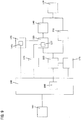
- the controller 199 includes a driving pulse signal generator 198 which generates the driving pulse signal to drive the electric motor 110.
- the driving pulse signal generator 198 increases the duty ratio of the driving pulse signal with respect to the standard duty ratio during the forward movement stroke in which the load applied on the electric motor 110 becomes relatively larger, and the driving pulse signal generator 198 decreases the duty ratio of the driving pulse signal with respect to the standard duty ratio during the backward movement stroke in which the load applied on the electric motor 110 becomes relatively smaller.
- the controller 199 based on the rotation speed fluctuation during one driving cycle of the piston 127, controls the rotation speed of the electric motor 110 in a following driving cycle which follows the one driving cycle.
- the controller 199 decides a future control of the electric motor 110 based on a history record of the rotation speed fluctuation of the electric motor 110.
- the duty ratio of the driving pulse signal is decided based on the maximum rotation speed and the minimum rotation speed of the electric motor 110 during the one driving cycle.
- the controller 199 measures a first time and a second time during the one driving cycle (hereinafter also called as a first driving cycle) based on the rotation speed fluctuation of the electric motor 110 detected by the rotation speed sensor 175.
- the first time is an elapsed time since the beginning of the one driving cycle until the rotation speed of the electric motor 110 reaches the maximum rotation speed of the electric motor 110.
- the second time is an elapsed time since the beginning of the one driving cycle until the rotation speed of the electric motor 110 reaches the minimum rotation speed of the electric motor 110.
- the beginning of the one driving cycle is defined as when the piston 127 is placed at its rear position.
- the forward movement stroke corresponds to a period substantially between the first time and the second time.
- the controller 199 changes the duty ratio of the driving pulse signal from the standard duty ratio in the following driving cycle (hereinafter also called as a second driving cycle) which follows the first driving cycle. Specifically, the controller 199 (driving pulse signal generator 198) increases the duty ratio of the driving pulse signal which is utilized during a period after the first time is passed since the beginning of the second driving cycle until the second time is passed since the beginning of the second driving cycle with respect to the standard duty ratio.
- the controller 199 utilizes the first and second time measured in the first driving cycle and the driving pulse signal generator 198 increases the duty ratio of the driving pulse signal which is utilized during a period after the first time is passed since the beginning of each driving cycle until the second time is passed since the beginning of each driving cycle with respect to the standard duty ratio. Accordingly, a decrease of the rotation speed of the electric motor 110 is prevented during the forward movement stroke in which the load applied on the electric motor 110 is relatively large.
- the controller 199 decreases the duty ratio of the driving pulse signal which is utilized during a period after the second time is passed since the beginning of the second driving cycle by utilizing the second time measured in the first driving cycle with respect to the standard duty ratio. Further, in the driving cycles following the second driving cycle, the controller 199, similar to the second driving cycle, utilizes the first and second time measured in the first driving cycle and the driving pulse signal generator 198 decreases the duty ratio of the driving pulse signal which is utilized during a period after the second time is passed since the beginning of each driving cycle with respect to the standard duty ratio. Accordingly, an inadvertent increase of the rotation speed of the electric motor 110 is prevented during the backward movement stroke in which the load applied on the electric motor 110 is relatively small.
- the driving pulse signal generator 198 increases the duty ratio of the driving pulse signal from the standard duty ratio in the forward movement stroke, and decreases the duty ratio of the driving pulse signal from the standard duty ratio in the backward movement stroke, however, it is not limited to this.
- the driving pulse signal generator 198 may change the duty ratio of the driving pulse signal which is only utilized during one of the forward movement stroke and the backward movement stroke from the standard duty ratio.
- the duty ratio of the driving pulse signal in the forward movement stroke is set to be larger than that in the backward movement stroke.
- the driving pulse signal generator 198 decides the duty ratio of the driving pulse signal in the driving cycles after the second driving cycle in the same way based on the rotation speed fluctuation of the electric motor 110 in the first driving cycle, however, it is not limited to this.
- the driving pulse signal generator 198 may decide the duty ratio only in the second driving cycle based on the rotation speed fluctuation of the electric motor 110 in the first driving cycle. That is, the duty ratio of the driving pulse signal in a third driving cycle following the second driving cycle may be decided based on the rotation speed fluctuation of the electric motor 110 in the second driving cycle.
- the driving pulse signal generator 198 may decide the duty ratio of the driving pulse signal which is utilized in the next driving cycle following one driving cycle.
- the duty ratio of the driving pulse signal is decided by the rotation fluctuation of the electric motor 110 in a single driving cycle during the hammer drill operation.
- the duty ratio of the driving pulse signal is decided by the rotation fluctuation of the electric motor 110 during a plurality of driving cycles. That is, the rotation speed fluctuation suppressing control in the second embodiment is different from that in the first embodiment.
- Other features in the hammer drill 100 in the second embodiment are similar to those in the first embodiment and explanation thereof is therefore omitted.
- the controller 199 measures each first and second time in each driving cycle. Each first time is an elapsed time since the beginning of each driving cycle until the rotation speed of the electric motor 110 reaches the maximum rotation speed of the electric motor 110 in each driving cycle. Each second time is an elapsed time since the beginning of each driving cycle until the rotation speed of the electric motor 110 reaches the minimum rotation speed of the electric motor 110 in each driving cycle. Further, the controller 199 calculates an average time (a first average time) of a plurality of the first times and an average time (a second average time) of a plurality of the second times. For example, the first average time and the second average time are calculated based on three first times and second times during three driving cycles, respectively. Further, the controller 199 (the driving pulse signal generator 198) decides the duty ratio of the driving pulse signal which is utilized in the driving cycle (hereinafter called as a following driving cycle) following the plurality of the driving cycles based on the first and second average times.
- the driving pulse signal generator 198 increases the duty ratio of the driving pulse signal which is utilized during a period after the first average time is passed since the beginning of the following driving cycle until the second average time is passed since the beginning of the following driving cycle with respect to the standard duty ratio.
- the driving pulse signal generator 198 decreases the duty ratio of the driving pulse signal which is utilized during a period after the second average time is passed since the beginning of the following driving cycle with respect to the standard duty ratio. That is, in each driving cycle, the duty ratio of the driving pulse which is utilized in each driving cycle is changed from the standard duty ratio in accordance with the first and second average times during the plurality of driving cycles prior to the each driving cycle.
- the duty ratio of the driving pulse signal during the forward movement stroke of the piston 127 is increased with respect to the standard duty ratio.
- a decrease of the rotation speed of the electric motor 110 caused by relatively large load applied on the electric motor 110 during the hammer drill operation is prevented.
- the duty ratio of the driving pulse signal during the backward movement stroke of the piston 127 is decreased with respect to the standard duty ratio.
- an inadvertent increase of the rotation speed of the electric motor 110 caused by relatively small load applied on the electric motor 110 during the hammer drill operation As a result, the rotation speed fluctuation of the electric motor 110 is suppressed and thereby the electric motor 110 is driven stably.
- the controller 199 decides the duty ratio of the driving pulse signal which is utilized in the following driving cycle based on the rotation speed fluctuation of the electric motor 110 during the driving cycle(s) prior to the following driving cycle. That is, based on the history of the periodic (cyclic) rotation speed fluctuation of the electric motor 110, the duty ratio of the driving pulse signal during the future driving cycle (following driving cycle) is decided. Thus, the periodic rotation speed fluctuation of the electric motor 110 during the following driving cycles is effectively prevented. Further, by averaging the maximum and minimum rotation speed of the electric motor 110 during the plurality of the driving cycles, the rotation speed fluctuation of the electric motor 110 during the following driving cycles is more effectively prevented.
- the controller 199 drives the electric motor 110 by the rotation speed fluctuation suppressing control during the hammer drill operation, and thereby the periodic rotation speed fluctuation of the electric motor 110 caused by the periodic load on the electric motor 110 in response to the periodic hammering movement of the hammer bit 119 is suppressed.
- the duty ratio as a control factor for controlling the electric motor 110 is changed with respect to the standard duty ratio, however, it is not limited to this.
- voltage value and/or current value of the driving pulse signal for driving the electric motor 110 may be utilized as a control factor. That is, voltage value and/or current value may be changed with respect to a standard voltage value and/or standard current value.
- the mode switching mechanism 155 switches to enable or disenable the rotation speed fluctuation suppressing control by the controller 199.
- rotation speed fluctuation suppressing control enabled state and disenabled state of the controller 199 against the electric motor 110 are switched based on a switching of the driving mode by the mode switching mechanism 155, however, it is not limited to this.
- an exclusive switch for switching the rotation speed fluctuation suppressing control enabled state and disenabled state may be provided.
- the exclusive switch may be manually operated by a user.
- the hammer drill 100 may be changeable in various ways.
- the electric motor 110 may be arranged such that the motor shaft 111 of the electric motor 110 is parallel to an axis line of the hammer bit 119.
- only one end of the hand grip 109 in its extending direction may be connected to the main housing 101. That is, the hand grip 109 may be formed as a cantilever, one end of which is connected to the main housing 101.
- a power supply cable may be provided instead of the battery mounting part 160. That is, the hammer drill 100 may be driven by electric current provided from an external power source through the power supply cable instead of the battery pack 161.
- the electric motor 110 may be provided as a brush motor instead of the brushless motor.
- the motion converting mechanism 120 may comprises a crank mechanism which includes a crank shaft and a connection rod instead of the swing member 125.
- the power tool according to this disclosure is not limited to the hammer drill.
- the power tool according to this disclosure includes a cutting machine which reciprocates a cutting blade such as an electric jigsaw or a reciprocating saw.
- a cutting of a workpiece by the cutting machine is performed during a forward movement or a backward movement of the blade.
- the load applied on the electric motor is increased in one of the forward movement or the backward movement corresponding to the cutting operation.
- the duty ratio of the driving pulse signal utilized during the forward movement is set to be larger than the standard duty ratio (reference duty ratio).
- the duty ratio of the driving pulse signal utilized during the backward movement is set to be larger than the standard duty ratio. That is, with respect to the driving cycle of the reciprocating movement of the blade, the duty ratio of the driving pulse signal utilized when the cutting of the workpiece is performed is set to be larger than the duty ratio of the driving pulse signal utilized when the cutting of the workpiece is not performed.
- a blade holding member which holds and reciprocates the blade is one example which corresponds to "a driving member" of this disclosure.
- the rotation speed fluctuation suppressing control is disabled and the standard duty ratio is utilized to the driving pulse signal for driving the electric motor.
- the hammer drill 100 is one example of a configuration that corresponds to "a power tool”.
- the hammer bit 119 is one example of a configuration that corresponds to "a tool bit”.
- the electric motor 110 is one example of a configuration that corresponds to "a motor”.
- the piston 127 is one example of a configuration that corresponds to "a driving member”.
- the striker 143 is one example of a configuration that corresponds to "a driving member”.
- the controller 199 is one example of a configuration that corresponds to "a controller".
- the mode switching mechanism 155 is one example of a configuration that corresponds to "a driving mode switching mechanism".
- the position sensor 170 is one example of a configuration that corresponds to "a position detector”.
- the rotation speed sensor 175 is one example of a configuration that corresponds to "a rotation speed detector”.
Description
- The present invention relates to a power tool which performs a predetermined operation.
-
DE 103 58 571 A1 , on which the preamble of claim 1 is based, discloses an impact tool in which a motor is controlled based on the detection of power consumption.EP 1 502 710 A2 discloses a power tool in which a motor is controlled based on the determination of the impact energy of a driving member. - Japanese non-examined laid-open Patent Publication No.
2004-255542 - In the electric hammer described above, the intermediate element hits the hammer bit while the hammer bit is pressed in the tool holder. In this case, the motor is driven at high speed in a state that the hammer bit is pressed in the tool holder (load applied state) compared to a state that the hammer bit is not pressed in the tool holder (no load state). In such a configuration, when the hammer bit is hit and the hammering operation is performed, a rotation speed of the motor is decreased due to the load applied on the motor and thereby the rotation speed of the motor in the load applied state becomes substantially same rotation speed of the motor in the no load state. However, during a reciprocating movement of the piston, the hammering element or the intermediate element as a driving member which drives the hammer bit, the load applied on the motor in a forward stroke of the driving member is different from the load applied on the motor in a backward stroke of the driving member. Thus, more sophisticated control for driving the motor is desired.
- Accordingly, an object of the present disclosure is, in consideration of the above described problem, to provide an improved control technique for driving a motor of a power tool.
- Above-mentioned problem is solved by providing a power tool according to claim 1.
- According to the invention, a power tool which drives a tool bit and performs a predetermined operation on a workpiece is provided. The power tool is, for example, constructed as an impact tool such as an electric hammer or an electric hammer drill, or a cutting tool such as an electric jigsaw or a reciprocating saw. In the power tool, as the tool bit is reciprocated, the power tool is also called as a reciprocating power tool. The power tool comprises a motor, a driving member which is driven by the motor and reciprocated, and a controller which controls the motor. The driving member drives the tool bit by means of its reciprocating movement.
- In the power tool, a forward movement stroke and a backward movement stroke of the driving member are defined based on the reciprocating movement. Thus, the forward movement stroke and the backward movement stroke define a driving cycle of the driving member. Further, the power tool is configured to perform the predetermined operation on the workpiece by the tool bit in response to one stroke among the forward and backward movement strokes.
- In the power tool, a control factor for controlling a driving of the motor is defined by at least one of a voltage value of a voltage applied on the motor and a duty ratio of a driving pulse signal utilized to drive the motor. Further, the controller is configured to set the control factor in said one stroke to be larger than that in the other stroke among the forward and backward movement strokes and drive the motor. Namely,
the predetermined operation is performed based on movement of the driving member during said one stroke. Thus, value of the control factor during said one stroke is set to be larger than value of the control factor during the other stroke. - Typically, a voltage value of the voltage applied on the motor during the said one stroke is set to be larger than the voltage value of the voltage applied on the motor during the other stroke, or a duty ratio of a driving pulse signal which is utilized to drive the motor during said one stroke is set to be larger than the duty ratio of the driving pulse signal during the other stroke.
The standard (reference) voltage value or the standard (reference) duty ratio may be defined, and the controller may set the voltage value and/or the duty ratio during said one stroke to be larger than the standard voltage value and/or the standard duty ratio, or the controller may set the voltage value and/or the duty ratio during the other stroke to be smaller than the standard voltage value and/or the standard duty ratio. In this case, the standard voltage value and/or the standard duty ratio may not be limited to a constant value. - Further, the power tool preferably comprises a position detector which detects a position of the driving member. The controller detects the forward movement stroke and/or the backward movement stroke of the driving member based on a detected result of a position of the driving member by the position detector.
- According to this aspect, the tool bit is driven in response to the forward movement stroke or the backward movement stroke of the reciprocated driving member and thereby the operation is performed. That is, for example, in a case that the operation is performed by a movement of the tool bit in response to the forward movement stroke of the driving member, the operation is not performed by a movement of the tool bit in response to the backward movement stroke of the driving member. During the operation corresponding to the forward movement stroke of the driving member, relatively high load is applied on the motor which drives the driving member. Accordingly, the controller sets the control factor in one of the forward movement stroke and the backward movement stroke of the driving member to be larger than that in the other stroke. In this case, the control factor in the forward movement stroke of the driving member, which causes the operation by the tool bit, is set to be larger than that in the backward movement stroke of the driving member. And the motor is driven and controlled by the controller by utilizing the control factor corresponding to each stroke. Thus, the rotation speed reduction of the motor due to the high load applied on the motor during the stroke of the driving member, which corresponds to the operation, is prevented. Such a driving control of the motor is also called as a rotation speed fluctuation suppressing control. With such a control by the controller, a range of the rotation speed fluctuation of the motor during one driving cycle becomes smaller. That is, by controlling the motor during the one driving cycle in detail more than well-known power tool, the rotation speed fluctuation of the motor during the one driving cycle is suppressed and the motor is stably driven. Further, since the rotation speed fluctuation of the motor due to the load applied on the motor is suppressed, work efficiency of the power tool during the operation is improved.
- According to a further preferable aspect of the present disclosure, the power tool comprises a rotation speed detector which detects a rotation speed of the motor. Further, the controller measures a first elapsed time and a second elapsed time during one driving cycle by utilizing a detected result of the rotation speed detector. The first elapsed time is defined by an elapsed time since the beginning of the one driving cycle until the maximum rotation speed of the motor during the one driving cycle is detected by the rotation speed detector. The second elapsed time is defined by an elapsed time since the beginning of the one driving cycle until the minimum rotation speed of the motor during the one driving cycle is detected by the rotation speed detector. Further, the controller is configured to set the control factor in the forward movement stroke and the control factor in the backward movement stroke in the following driving cycle which follows the one driving cycle based on the first and second elapsed times. Accordingly, based on a rotation speed fluctuation of the motor during the predetermined driving cycle, the controller suppresses the rotation speed fluctuation of the motor in the following driving cycle which follows the predetermined driving cycle. That is, the controller predicts the rotation speed fluctuation of the motor in the future driving cycle based on a history of the rotation speed fluctuation of the motor. Thus, the rotation speed fluctuation of the motor in the future driving cycle is effectively suppressed.
- According to a further preferable aspect of the present disclosure, the controller calculates a first average time and a second average time. The first average time is an average time of the first elapsed times in a plurality of the driving cycles . The second average time is an average time of the second elapsed times in said plurality of the driving cycles. Further, the controller is configured to set the control factor in the forward movement stroke and the control factor in the backward movement stroke based on the first and second average times in the following driving cycle which follows said plurality of the driving cycles. The controller may set each control factor in the forward and backward movement strokes based on the first and second average times in the following several driving cycles which continuously follow said plurality of driving cycles for calculating the first and second average times. By utilizing history of the rotation speed fluctuation of the motor during the plurality of driving cycles, the rotation speed fluctuation of the motor in the future driving cycle(s) is more effectively suppressed.
- According to a further preferable aspect of the present disclosure, the power tool comprises a switching mechanism which switches to enable/disenable a motor driving control in which the controller sets the control factor in said one stroke to be larger than that in the other stroke. The motor driving control is also called as a rotation speed fluctuation suppressing control. Accordingly, the motor driving control by the controller is enabled or disenabled by switching mechanism.
- According to a further preferable aspect of the present disclosure, the power tool is constructed as an electric hammer drill which has a drill mode and a hammer mode as driving modes. In the drill mode, the tool bit is rotationally driven around its longitudinal direction. In the hammer mode, the tool bit is at least linearly driven in its longitudinal direction. The power tool comprises a driving mode switching mechanism which switches the driving mode between the drill mode and the hammer mode. When the driving mode is switched to the drill mode by the driving mode switching mechanism, the motor driving control by the controller is disabled. Further, when the driving mode is switched to the hammer mode by the driving mode switching mechanism, the motor driving control by the controller is enabled. Typically, the driving mode switching mechanism is interlocked with the controller the motor driving control by the controller is automatically enabled and disabled by switching the driving mode by the driving mode switching mechanism. In the hammer mode, the tool bit may also be rotationally driven around its longitudinal direction. Thus, in the hammer mode, a hammering operation in which the tool bit is only linearly driven and/or a hammer drill operation in which the tool bit is linearly and rotationally driven may be accomplished. In the hammer mode, the driving member is periodically reciprocated by the motor, and thereby the tool bit is periodically reciprocated. Namely, load applied on the motor is periodically fluctuated. Accordingly, a frequency of the load fluctuation on the motor is obvious, and the rotation speed fluctuation is effectively suppressed by the motor driving control.
- Accordingly, an improved control technique for driving a motor of a power tool is provided.
- Other objects, features and advantages of the present disclosure will be readily understood after reading the following detailed description together with the accompanying drawings and the claims.
-
-
Fig. 1 shows a cross sectional side view of a hammer drill of a representative embodiment according to the present disclosure. -
Fig. 2 shows a cross sectional view of a mode switching mechanism of the hammer drill. -
Fig. 3 shows a cross sectional view of the mode switching mechanism of the hammer drill. -
Fig. 4 shows a cross sectional view of a driving of a piston in which the piston is positioned in its front position. -
Fig. 5 shows a cross sectional view of a driving of a piston in which the piston is positioned in its neutral position. -
Fig. 6 shows a cross sectional view of a driving of a piston in which the piston is positioned in its rear position. -
Fig. 7 shows a rotation speed fluctuation of a motor in a state that a hammer drill operation is not performed by a well-known hammer drill without a rotation speed fluctuation suppressing control. -
Fig. 8 shows a rotation speed fluctuation of the motor in a state that the hammer drill operation is performed by the well-known hammer drill without the rotation speed fluctuation suppressing control. -
Fig. 9 shows a block diagram of a control system of the hammer drill according to the present disclosure. - Each of the additional features and method steps disclosed above and below may be utilized separately or in conjunction with other features and method steps to provide and manufacture improved power tools and method for using such power tools and devices utilized therein. Representative examples of the invention, which examples utilized many of these additional features and method steps in conjunction, will now be described in detail with reference to the drawings. This detailed description is merely intended to teach a person skilled in the art further details for practicing preferred aspects of the present teachings and is not intended to limit the scope of the invention. Only the claims define the scope of the claimed invention. Therefore, combinations of features and steps disclosed within the following detailed description may not be necessary to practice the invention in the broadest sense, and are instead taught merely to particularly describe some representative examples of the invention, which detailed description will now be given with reference to the accompanying drawings.
- A first embodiment of the present disclosure is explained with reference to
Fig. 1 to Fig. 9 . In the first embodiment, a hand-held electrical hammer drill is utilized to explain as one example of a power tool. As shown inFig. 1 , ahammer drill 100 is a power tool which has ahammer bit 119 attached to a front end region of amain housing 101 and performs a chipping operation or a hammer drill operation on a workpiece (e.g. concrete) by causing a striking movement in an axial direction of thehammer bit 119 and a rotational movement around the axial direction of thehammer bit 119. Thehammer bit 119 is one example which corresponds to "a tool bit" of this disclosure. - The
hammer drill 100 is mainly provided with themain housing 101 which forms an outline of thehammer drill 100. Thehammer bit 119 is detachably attached to the front end region of themain housing 101 via atool holder 130. Thehammer bit 119 is inserted into a bit insertion hole of thetool holder 130 and held such that it is allowed to reciprocate in its axial direction (longitudinal direction) with respect to thetool holder 130 and prevented from rotating in its circumferential direction with respect to thetool holder 130. Accordingly, the power tool according to this disclosure may be also called as a reciprocating power tool. - The
main housing 101 is mainly provided with a motor housing which houses anelectric motor 110 and agear housing 105 which houses amotion converting mechanism 120, ahammering mechanism 140 and arotation transmitting mechanism 150. Ahand grip 109 is connected to themain housing 101 at a side opposite to thehammer bit 119 in the longitudinal direction of thehammer bit 119. Thehand grip 109 includes agrip portion 109A which is held by a user. Thegrip portion 109A extends in a direction (a vertical direction inFig. 1 ) crossing the longitudinal direction of thehammer bit 119. An upper end region of thegrip portion 109A is connected to thegear housing 105. The upper end region of thegrip portion 109A is close to an axial line of thehammer bit 119. A lower end region of thegrip portion 109A is connected to themotor housing 103. The lower end region of thegrip portion 109A is remote from the axial line of thehammer bit 119. Thegrip portion 109A is partly disposed on the axial line of thehammer bit 119. For convenience of explanation, thehammer bit 119 side of thehammer drill 100 in the longitudinal direction of thehammer bit 119 is defined as front side, and thehand grip 109 side of thehammer drill 100 in the longitudinal direction of thehammer bit 119 is defined as rear side. Further, with respect to an extending direction of thegrip portion 109A, a connection region side between thegrip portion 109A and thegear housing 105, which is close to the axial line of thehammer bit 119, is defined as upper side, and a connection region side between thegrip portion 109A and themotor housing 103, which is remote from the axial line of thehammer bit 119, is defined as lower side. - The
gear housing 105 is arranged at a front side of thehammer drill 100 and themotor housing 103 is arranged below thegear housing 105. Thehand grip 109 is connected to a rear end region of thegear housing 105. Theelectric motor 110 housed in themotor housing 103 is provided as a brushless motor. In the hand-heldhammer drill 100, a small size motor is utilized as theelectric motor 110 for saving the weight of thehammer drill 100. Theelectric motor 110 is arranged such that amotor shaft 111 of theelectric motor 110 crosses an axial line of thehammer bit 119. The axial line of thehammer bit 119 is also called as a hammering axis. That is, themotor shaft 111 extends in a vertical direction of thehammer drill 100. Acontroller 199 which controls driving of theelectric motor 110 is arranged below theelectric motor 110. Theelectric motor 110 and thecontroller 199 are examples which correspond to "a motor" and "a controller" of this disclosure, respectively. - Rotation of the
motor shaft 111 of theelectric motor 110 is converted into a linear motion by themotion converting mechanism 120 and then transmitted to thehammering mechanism 140. As a result, a hammering force (impact force) is generated in the longitudinal direction of thehammer bit 119 via thehammering mechanism 140. Further, rotation of themotor shaft 111 of theelectric motor 110 is transmitted to thetool holder 130 via therotation transmitting mechanism 150 and thereby thehammer bit 119 is rotationally driven around its longitudinal direction. Theelectric motor 110 is driven when atrigger 109a which is arranged on thehand grip 109 is pulled (manipulated). - As shown in
Fig. 1 , themotion converting mechanism 120 is arranged above themotor shaft 111 of theelectric motor 110. Themotion converting mechanism 120 is mainly provided with anintermediate shaft 121 which is rotationally driven by themotor shaft 111, arotating element 123 which is mounted onto theintermediate shaft 121, aswing member 125 which is swung in a front-rear direction of thehammer drill 100 by rotation of the rotating element 123 (intermediate shaft 121), acylindrical piston 127 which is reciprocated in the front-rear direction of thehammer drill 100 by swing motion of theswing member 125, and acylinder 129 which houses thepiston 127 in a slidable manner. Theintermediate shaft 121 is arranged perpendicular to themotor shaft 111. Thepiston 127 is a cylindrical member with bottom and slidably houses astriker 143 therein. Thecylinder 129 forms a rear end region of thetool holder 130, that is, thecylinder 129 is formed integrally with thetool holder 130. - As shown in
Fig. 1 , thehammering mechanism 140 is arranged forward of themotion converting mechanism 120 and rearward of thetool holder 130. Thehammering mechanism 140 is mainly provided with a hammering element in the form of thestriker 143 which is slidably arranged within thepiston 127 and an intermediate element in the form of animpact bolt 145 which is arranged forward of thestriker 143. An inner space of thepiston 127 rearward of thestriker 143 forms anair chamber 127a which serves as an air spring. Thus, by the swing motion of theswing member 125 in the front-rear direction of thehammer drill 100, thepiston 127 is reciprocated in the front-rear direction and thereby thestriker 143 is driven. That is, when thepiston 127 is moved forward, thestriker 143 is moved forward by the air spring and hits theimpact bolt 145 and therefore hammering force of thehammer bit 119 is generated via theimpact bolt 145. As a result, a hammering operation on a workpiece is performed by thehammer bit 119. Further, when thepiston 127 is moved rearward, negative air pressure which is lower pressure than the atmospheric pressure is occurred within theair chamber 127a and thereby thestriker 143 is moved rearward. Further, thestriker 143 and theimpact bolt 145 are moved rearward by reaction force from a workpiece hammered by thehammer bit 119. As a result, thestriker 143 and theimpact bolt 145 are reciprocated in the front-rear direction of thehammer drill 100. In such a construction, as thestriker 143 and theimpact bolt 145 are driven by the air spring, thestriker 143 and theimpact bolt 145 are moved behind a movement phase of thepiston 127. - As shown in
Fig. 1 , therotation transmitting mechanism 150 is arranged forward of themotion converting mechanism 120 and below thehammering mechanism 140. Therotation transmitting mechanism 150 is mainly provided with a gear deceleration mechanism which includes a plurality of gears such as afirst gear 151 which is rotated integrally with theintermediate shaft 121 and asecond gear 153 which is engaged with thefirst gear 151. Thesecond gear 153 is mounted onto the tool holder 130 (cylinder 129) so as to rotate integrally with thetool holder 130. Thus, rotation of thefirst gear 151 is transmitted to thetool holder 130 via thesecond gear 153 and thereby thehammer bit 119 attached to thetool holder 130 is rotated. - As shown in
Fig. 1 , abattery mounting part 160 to which abattery pack 161 is detachably attached is disposed on themotor housing 103 below thehand grip 109. Thebattery mounting part 160 is electrically connected to thecontroller 199. Thus, when thetrigger 109a is operated, thecontroller 199 provides electric current from thebattery pack 161 to theelectric motor 110 and thereby theelectric motor 110 is driven. - The
hammer drill 100 has a hammer drill mode and a drill mode as driving modes. In the hammer drill mode, thehammer bit 119 makes a hammering movement in its longitudinal direction and a rotational movement around its longitudinal direction. Thus, the hammer drill operation is performed on a workpiece. In the drill mode, thehammer bit 119 only makes the rotational movement without the hammering movement. Thus, the drill operation is performed on a workpiece. - As shown in
Fig. 2 and Fig. 3 , the driving mode is switched by amode switching mechanism 155. Themode switching mechanism 155 mainly includes arotation transmitting member 157 and aswitching dial 159. Therotation transmitting member 157 is formed as a cylindrical member and movable against theintermediate shaft 121 in an axial direction of theintermediate shaft 121. Therotation transmitting member 157 is connected to theintermediate shaft 121 by a spline connection, and thereby therotation transmitting member 157 is rotated integrally with theintermediate shaft 121 via the spline connection. Therotation transmitting member 157 has afirst engagement part 157a which is engageable with anengagement recess 123a which is formed on the front region of the rotatingmember 123, and asecond engagement part 157b which is engageable with theswitching dial 159. Thefirst engagement part 157a is formed on an inner surface of therotation transmitting member 157. Thefirst engagement part 157a is provided as a spline groove which makes a spline connection with theengagement recess 123a. Thesecond engagement part 157b is formed on an outer surface of therotation transmitting member 157. Thesecond engagement part 157b is provided as a cam groove extending in the circumference direction of therotation transmitting member 157. - The
switching dial 159 is arranged so as to protrude horizontally from the side surface of thegear housing 105. Theswitching dial 159 is rotatable around its axis extending in a lateral direction of the hammer drill 100 (vertical direction inFig. 2 ) perpendicular to the longitudinal direction of the hammer bit 119 (lateral direction inFig. 2 ). Theswitching dial 159 mainly includes aknob 159a which is manually operated by a user, and anengagement protrusion 159b which is engaged with thesecond engagement part 157b of therotation transmitting member 157. Theengagement protrusion 159b is substantially conical-shaped part around its axis which is offset (eccentric) from the rotation axis of theswitching dial 159. Thus, when theknob 159a is operated and theswitching dial 159 is rotated, theengagement protrusion 159b is moved in the front-rear direction of thehammer drill 100. Accordingly, therotation transmitting member 157 which is engaged with theengagement protrusion 159b is moved in the front-rear direction of thehammer drill 100. That is, therotation transmitting member 157 is moved between its front position and its rear position by rotation of theswitching dial 159. Themode switching mechanism 155 is one example which corresponds to "a driving mode switching mechanism" of this disclosure. - As shown in
Fig.2 , when therotation transmitting member 157 is placed at its rear position, thefirst engagement part 157a of therotation transmitting member 157 engages with theengagement recess 123a of the rotatingmember 123. Thus, rotation of theintermediate shaft 121 is transmitted to the rotatingmember 123 via therotation transmitting member 157 and thereby themotion converting mechanism 120 is driven. As a result, thehammering mechanism 140 is driven and thehammer bit 119 is reciprocated in its longitudinal direction. Further, rotation of theintermediate shaft 121 is transmitted to thesecond gear 153 via thefirst gear 151 and thetool holder 130 is rotated via thecylinder 129. Thus, thehammer bit 119 is rotated around its longitudinal direction. Accordingly, when therotation transmitting member 157 is placed at its rear position, the hammer drill mode is set and the hammer drill operation in which thehammer bit 119 makes the rotation movement and the hammering movement is performed. - On the other hand, as shown in
Fig. 3 , when therotation transmitting member 157 is placed at its front position, thefirst engagement part 157a of therotation transmitting member 157 does not engage with theengagement recess 123a of the rotatingmember 123. That is, rotation of theintermediate shaft 121 is not transmitted to the rotatingmember 123. Thus, themotion converting mechanism 120 is not driven and thehammer bit 119 only makes the rotation movement by therotation transmitting mechanism 150. Accordingly, when therotation transmitting member 157 is placed at its front position, the drill mode is set and the drill operation in which thehammer bit 119 only makes the rotation movement is performed. - In the hammer drill mode, when the
electric motor 110 is driven, thepiston 127 is driven via theswing member 125. That is, as shown inFig. 4 to Fig. 6 , thepiston 127 is reciprocated between a front position and a rear position. Right side inFig. 4 to Fig. 6 corresponds to the front side of thehammer drill 100, and left side inFig. 4 to Fig. 6 corresponds to the rear side of thehammer drill 100.Fig. 4 shows the front position of thepiston 127 and theswing member 125.Fig. 6 shows the rear position of thepiston 127 and theswing member 125.Fig. 5 shows an intermediate position of thepiston 127 and theswing member 125 between the front positon and the rear position. When thepiston 127 is driven, volume of theair chamber 127a is fluctuated and thereby air inside theair chamber 127a serves as the air spring which acts on thestriker 143. InFig. 4 to Fig. 6 , illustration of thestriker 143 is omitted. - When the
piston 127 is moved from the rear position toward the front position close to thehammer bit 119, air inside theair chamber 127a is compressed. The movement of thepiston 127 from the rear position to the front position is one example which corresponds to "a forward movement stroke" of this disclosure. Further, the forward movement stroke is also called as a compression stroke or a driving stroke. On the other hand, when thepiston 127 is moved from the front position toward the rear position, the air inside theair chamber 127a is expanded. The movement of thepiston 127 from the front position to the rear position is one example which corresponds to "a backward movement stroke" of this disclosure. Further, the backward movement stroke is also called as an expansion stroke or a non-driving stroke. As described above, a driving cycle of thepiston 127 is provided by the forward movement stroke and the backward movement stroke of thepiston 127. Thepiston 127 is one example which corresponds to "a driving member" of this disclosure. - In the forward movement stroke, the air inside the
air chamber 127a is compressed and thereby thestriker 143 moves forward and hits theimpact bolt 145. Thus, thehammer bit 119 is collided by theimpact bolt 145 and therefore thehammer bit 119 performs a hammer operation on a workpiece. At this time, thehammer bit 119 is rotationally driven by therotation transmitting mechanism 150. Accordingly, in response to the forward movement stroke, thehammer bit 119 performs the hammer drill operation on a workpiece . On the other hand, in the backward movement stroke, the air inside theair chamber 127a is expanded and thereby air pressure in theair chamber 127a becomes lower than the atmospheric pressure. Accordingly, thestriker 143 is moved rearward as a return movement. - As described above, air pressure in the
air chamber 127a is fluctuated by reciprocating movement of thepiston 127, and thereby load applied on theelectric motor 110 which drives thepiston 127 is also fluctuated. Thus, a rotation speed fluctuation of theelectric motor 110 is occurred. During the forward movement stroke, the air pressure in theair chamber 127a becomes gradually high, and when the air pressure reaches the predetermined value, thestriker 143 is driven (moved) forward. Accordingly, the load applied on theelectric motor 110 becomes larger in accordance with the air pressure in theair chamber 127a during the forward movement stroke. Namely, the rotation speed of theelectric motor 110 tends to be lower when the load applied on theelectric motor 110 becomes larger. On the other hand, during the backward movement stroke, thestriker 143 receives reaction force from theimpact bolt 145 when thestriker 143 collides with theimpact bolt 145 and a negative air pressure in theair chamber 127a is occurred. Therefore, thestriker 143 is moved rearward by the reaction force and the negative air pressure. Accordingly, the load applied on theelectric motor 110 is smaller compared to that during the forward movement stroke. Namely, the rotation speed of theelectric motor 110 tends to be higher when the load applied on theelectric motor 110 becomes smaller. Based on the fact described above, thecontroller 199 controls a driving of theelectric motor 110 such that theelectric motor 110 is driven within a predetermined range of the rotation speed. Namely, the rotation speed fluctuation of theelectric motor 110 is kept within the predetermined range of the rotation speed by thecontroller 199. In other words, thecontroller 199 controls theelectric motor 110 under substantially constant rotation speed state. Such a control is also called as a constant rotation speed control. - Generally, in the constant rotation speed control, the controller compares the rotation speed of the driving electric motor with a predetermined rotation speed (standard rotation speed) . When the rotation speed exceeds an upper limit threshold defined in response to the standard rotation speed, the controller controls the electric motor so as to reduce the rotation speed of the electric motor. On the other hand, when the rotation speed is below a lower limit threshold defined in response to the standard rotation speed, the controller controls the electric motor so as to increase the rotation speed of the electric motor. The controller outputs a driving pulse signal to the electric motor and controls the electric motor. That is, the electric motor is controlled on the basis of a PWM (Pulse Width Modulation) control signal by controller. Specifically, the rotation speed of the electric motor is increased by increasing a duty ratio of the driving pulse signal outputted to the electric motor. On the other hand, the rotation speed of the electric motor is decreased by decreasing the duty ratio of the driving pulse signal outputted to the electric motor. In this case, a standard duty ratio (reference duty ratio) of the driving pulse signal is defined by a duty ratio of the driving pulse signal which drives the electric motor at the predetermined substantially constant rotation speed under no-load state.
- During the hammer drill operation, the
hammer bit 119 is pressed against a workpiece (e.g. concreate) . Thus, thestriker 143 receives reaction force via theimpact bolt 145 in response to hammering force of thehammer bit 119 and thereby thestriker 143 is moved rearward. That is, thestriker 143 is placed more rearward during the hammer drill operation compared to thestriker 143 when the hammer drill operation is not performed. In other words, the rear position of thestriker 143 is changed in response to the magnitude of pressing force of thehammer bit 119 during the hammer drill operation. On the other hand, thepiston 127 is moved between the predetermined front position and rear position regardless of the hammer drill operation. Accordingly, a distance between thepiston 127 and thestriker 143 placed at the rear position during the hammer drill operation is shorter compared to that when the hammer drill operation is not performed. Thus, air within theair chamber 127a is more compressed during the hammer drill operation. An air compression rate in theair chamber 127a during the forward movement stroke in the hammer drill operation becomes higher, and thereby load applied on theelectric motor 110 which drives thepiston 127 becomes larger. As a result, the rotation speed of theelectric motor 110 during the forward movement stroke in the hammer drill operation is decreased compared to that when the hammer drill operation is not performed. On the other hand, during the backward movement in the hammer drill operation, thestriker 143 receives the reaction force from a workpiece via theimpact bolt 145, and thereby the load applied on theelectric motor 110 which drives thepiston 127 becomes smaller. As a result, the load applied on theelectric motor 110 during the backward movement stroke in the hammer drill operation becomes smaller compared to that when the hammer drill operation is not performed, and thereby the rotation speed of theelectric motor 110 is increased. That is, during the hammer drill operation, the rotation speed of theelectric motor 110 is dramatically changed. - Specifically, as shown in
Fig. 7 , in a well-known hammer drill, when the hammer drill operation is not performed, the rotation speed of the electric motor is fluctuated periodically substantially between a rotation speedupper limit 310 and a rotation speedlower limit 320 which are defined around astandard rotation speed 300 as a center rotation speed in response to a reciprocating movement of the piston. That is, the controller controls the electric motor such that the rotation speed of the electric motor is changed within the predetermined range. On the other hand, in a case that the same control as described above is utilized during the hammer drill operation, since the rotation speed fluctuation is relatively larger during the hammer drill operation as shown inFig. 8 , the rotation speed of the electric motor may possibly be much larger than the rotation speedupper limit 310 or may possibly be much less than the rotation speedlower limit 320. In a case that the rotation speed of the electric motor is below the rotation speedlower limit 320, output (torque multiplied by the rotation speed) of the electric motor becomes smaller and thereby a hammer drill operation efficiency becomes lower. Further, in a case that the rotation speed of the electric motor is above the rotation speedupper limit 310, output of the electric motor becomes unnecessarily larger. InFig. 7 and Fig. 8 , a unit of the horizontal axis is time (second) and a unit of the vertical axis is a rotation speed (rpm) of the electric motor. Further, the rotation speed fluctuations are shown by rotationspeed fluctuation waveforms Fig. 7 and Fig. 8 , respectively. - In a small size
electric motor 110 of thehammer drill 100, the moment of inertia of a rotor is relatively small and therefore large rotation speed fluctuation may be occurred by load applied on theelectric motor 110. Thus, in the hammer drill mode (hammer drill operation), the rotation speed of theelectric motor 110 may remarkably go out of the predetermined range of the rotation speed which is defined for the constant rotation speed control. Accordingly, thecontroller 199 changes the duty ratio of the driving pulse signal from the standard duty ratio based on the load applied on theelectric motor 110 and drives theelectric motor 110 so that theelectric motor 110 is driven within the predetermined range of the rotation speed in the hammer drill mode. As a result, thecontroller 199 prevents the rotation speed of theelectric motor 110 from going out of the predetermined range of the rotation speed. In other words, thecontroller 199 suppresses the rotation speed fluctuation of theelectric motor 110. Such a control based on the load applied on theelectric motor 110 is also called as a rotation speed fluctuation suppressing control. Further, in the drill mode (drill operation), the rotation speed is also fluctuated by load applied on theelectric motor 110. However, as the rotation speed fluctuation during the drill operation is not occurred periodically, thecontroller 199 does not change the duty ratio of the driving pulse signal from the standard duty ratio in the drill mode. That is, in the drill mode, the constant rotation speed control is performed but the rotation speed fluctuation suppressing control is not performed. Accordingly, when the hammer drill mode is selected by themode switching mechanism 155, the rotation speed fluctuation suppressing control to theelectric motor 110 is activated by thecontroller 199 and when the drill mode is selected by themode switching mechanism 155, the rotation speed fluctuation suppressing control to theelectric motor 110 is deactivated. - Specifically, as shown in
Fig. 9 , aposition sensor 170 which detects a position of thepiston 127 for detecting the forward movement stroke and/or the backward movement stroke of thepiston 127 is provided. Thus, thecontroller 199 detects the forward movement stroke and/or the backward movement stroke based on a detected result of theposition sensor 170. Further, arotation speed sensor 175 which measures the rotation speed of theelectric motor 110 for detecting the load applied on theelectric motor 110 is provided. Thus, thecontroller 199 detects the load applied on theelectric motor 110 based on a detected result of therotation speed sensor 175. Further, thecontroller 199 links the rotation speed fluctuation of theelectric motor 110 to the driving stroke of the forward movement stroke or the backward movement stroke of thepiston 127. Theposition sensor 170 and therotation speed sensor 175 may be provided as an electromagnetic sensor or an optical sensor like that. - Further, as shown in
Fig. 9 , thecontroller 199 is connected to aswitch 155a of themode switching mechanism 155. Theswitch 155a is turned on or off based on the driving mode selected by themode switching mechanism 155. When the hammer drill mode is selected, theswitch 155a is turned on and when the drill mode is selected, theswitch 155a is turned off. Thecontroller 199 includes a drivingpulse signal generator 198 which generates the driving pulse signal to drive theelectric motor 110. - When the hammer drill mode is selected and the
controller 199 detects the ON state of theswitch 155a, the drivingpulse signal generator 198 increases the duty ratio of the driving pulse signal with respect to the standard duty ratio during the forward movement stroke in which the load applied on theelectric motor 110 becomes relatively larger, and the drivingpulse signal generator 198 decreases the duty ratio of the driving pulse signal with respect to the standard duty ratio during the backward movement stroke in which the load applied on theelectric motor 110 becomes relatively smaller. Thecontroller 199, based on the rotation speed fluctuation during one driving cycle of thepiston 127, controls the rotation speed of theelectric motor 110 in a following driving cycle which follows the one driving cycle. In other words, thecontroller 199 decides a future control of theelectric motor 110 based on a history record of the rotation speed fluctuation of theelectric motor 110. The duty ratio of the driving pulse signal is decided based on the maximum rotation speed and the minimum rotation speed of theelectric motor 110 during the one driving cycle. - Specifically, the
controller 199 measures a first time and a second time during the one driving cycle (hereinafter also called as a first driving cycle) based on the rotation speed fluctuation of theelectric motor 110 detected by therotation speed sensor 175. The first time is an elapsed time since the beginning of the one driving cycle until the rotation speed of theelectric motor 110 reaches the maximum rotation speed of theelectric motor 110. The second time is an elapsed time since the beginning of the one driving cycle until the rotation speed of theelectric motor 110 reaches the minimum rotation speed of theelectric motor 110. The beginning of the one driving cycle is defined as when thepiston 127 is placed at its rear position. Accordingly, in the driving cycle, as the forward movement stroke is prior to the backward movement stroke of thepiston 127, the first time is shorter than the second time. In the forward movement stroke, the load applied on theelectric motor 110 becomes larger and thereby the rotation speed of theelectric motor 110 tends to be decreased. In such a configuration, the forward movement stroke corresponds to a period substantially between the first time and the second time. - Based on the first and second time measured in the first driving cycle, the controller 199 (driving pulse signal generator 198) changes the duty ratio of the driving pulse signal from the standard duty ratio in the following driving cycle (hereinafter also called as a second driving cycle) which follows the first driving cycle. Specifically, the controller 199 (driving pulse signal generator 198) increases the duty ratio of the driving pulse signal which is utilized during a period after the first time is passed since the beginning of the second driving cycle until the second time is passed since the beginning of the second driving cycle with respect to the standard duty ratio. Further, in driving cycles following the second driving cycle, the
controller 199, similar to the second driving cycle, utilizes the first and second time measured in the first driving cycle and the drivingpulse signal generator 198 increases the duty ratio of the driving pulse signal which is utilized during a period after the first time is passed since the beginning of each driving cycle until the second time is passed since the beginning of each driving cycle with respect to the standard duty ratio. Accordingly, a decrease of the rotation speed of theelectric motor 110 is prevented during the forward movement stroke in which the load applied on theelectric motor 110 is relatively large. - Further, the controller 199 (driving pulse signal generator 198) decreases the duty ratio of the driving pulse signal which is utilized during a period after the second time is passed since the beginning of the second driving cycle by utilizing the second time measured in the first driving cycle with respect to the standard duty ratio. Further, in the driving cycles following the second driving cycle, the
controller 199, similar to the second driving cycle, utilizes the first and second time measured in the first driving cycle and the drivingpulse signal generator 198 decreases the duty ratio of the driving pulse signal which is utilized during a period after the second time is passed since the beginning of each driving cycle with respect to the standard duty ratio. Accordingly, an inadvertent increase of the rotation speed of theelectric motor 110 is prevented during the backward movement stroke in which the load applied on theelectric motor 110 is relatively small. - As described above, the driving
pulse signal generator 198 increases the duty ratio of the driving pulse signal from the standard duty ratio in the forward movement stroke, and decreases the duty ratio of the driving pulse signal from the standard duty ratio in the backward movement stroke, however, it is not limited to this. For example, the drivingpulse signal generator 198 may change the duty ratio of the driving pulse signal which is only utilized during one of the forward movement stroke and the backward movement stroke from the standard duty ratio. In other words, the duty ratio of the driving pulse signal in the forward movement stroke is set to be larger than that in the backward movement stroke. - Further, the driving
pulse signal generator 198 decides the duty ratio of the driving pulse signal in the driving cycles after the second driving cycle in the same way based on the rotation speed fluctuation of theelectric motor 110 in the first driving cycle, however, it is not limited to this. For example, the drivingpulse signal generator 198 may decide the duty ratio only in the second driving cycle based on the rotation speed fluctuation of theelectric motor 110 in the first driving cycle. That is, the duty ratio of the driving pulse signal in a third driving cycle following the second driving cycle may be decided based on the rotation speed fluctuation of theelectric motor 110 in the second driving cycle. In other words, based on the load applied on theelectric motor 110 in the one driving cycle, the drivingpulse signal generator 198 may decide the duty ratio of the driving pulse signal which is utilized in the next driving cycle following one driving cycle. - Next, a second embodiment of this disclosure is explained. In the first embodiment, the duty ratio of the driving pulse signal is decided by the rotation fluctuation of the
electric motor 110 in a single driving cycle during the hammer drill operation. On the other hand, in the second embodiment, the duty ratio of the driving pulse signal is decided by the rotation fluctuation of theelectric motor 110 during a plurality of driving cycles. That is, the rotation speed fluctuation suppressing control in the second embodiment is different from that in the first embodiment. Other features in thehammer drill 100 in the second embodiment are similar to those in the first embodiment and explanation thereof is therefore omitted. - The
controller 199 measures each first and second time in each driving cycle. Each first time is an elapsed time since the beginning of each driving cycle until the rotation speed of theelectric motor 110 reaches the maximum rotation speed of theelectric motor 110 in each driving cycle. Each second time is an elapsed time since the beginning of each driving cycle until the rotation speed of theelectric motor 110 reaches the minimum rotation speed of theelectric motor 110 in each driving cycle. Further, thecontroller 199 calculates an average time (a first average time) of a plurality of the first times and an average time (a second average time) of a plurality of the second times. For example, the first average time and the second average time are calculated based on three first times and second times during three driving cycles, respectively. Further, the controller 199 (the driving pulse signal generator 198) decides the duty ratio of the driving pulse signal which is utilized in the driving cycle (hereinafter called as a following driving cycle) following the plurality of the driving cycles based on the first and second average times. - In the following driving cycle, the driving
pulse signal generator 198 increases the duty ratio of the driving pulse signal which is utilized during a period after the first average time is passed since the beginning of the following driving cycle until the second average time is passed since the beginning of the following driving cycle with respect to the standard duty ratio. On the other hand, the drivingpulse signal generator 198 decreases the duty ratio of the driving pulse signal which is utilized during a period after the second average time is passed since the beginning of the following driving cycle with respect to the standard duty ratio. That is, in each driving cycle, the duty ratio of the driving pulse which is utilized in each driving cycle is changed from the standard duty ratio in accordance with the first and second average times during the plurality of driving cycles prior to the each driving cycle. - According to the first and second embodiments, the duty ratio of the driving pulse signal during the forward movement stroke of the
piston 127 is increased with respect to the standard duty ratio. Thus, a decrease of the rotation speed of theelectric motor 110 caused by relatively large load applied on theelectric motor 110 during the hammer drill operation is prevented. Further, the duty ratio of the driving pulse signal during the backward movement stroke of thepiston 127 is decreased with respect to the standard duty ratio. Thus, an inadvertent increase of the rotation speed of theelectric motor 110 caused by relatively small load applied on theelectric motor 110 during the hammer drill operation. As a result, the rotation speed fluctuation of theelectric motor 110 is suppressed and thereby theelectric motor 110 is driven stably. - Further, the
controller 199 decides the duty ratio of the driving pulse signal which is utilized in the following driving cycle based on the rotation speed fluctuation of theelectric motor 110 during the driving cycle(s) prior to the following driving cycle. That is, based on the history of the periodic (cyclic) rotation speed fluctuation of theelectric motor 110, the duty ratio of the driving pulse signal during the future driving cycle (following driving cycle) is decided. Thus, the periodic rotation speed fluctuation of theelectric motor 110 during the following driving cycles is effectively prevented. Further, by averaging the maximum and minimum rotation speed of theelectric motor 110 during the plurality of the driving cycles, the rotation speed fluctuation of theelectric motor 110 during the following driving cycles is more effectively prevented. - Further, the
controller 199 drives theelectric motor 110 by the rotation speed fluctuation suppressing control during the hammer drill operation, and thereby the periodic rotation speed fluctuation of theelectric motor 110 caused by the periodic load on theelectric motor 110 in response to the periodic hammering movement of thehammer bit 119 is suppressed. - In the first and second embodiments, the duty ratio as a control factor for controlling the
electric motor 110 is changed with respect to the standard duty ratio, however, it is not limited to this. For example, voltage value and/or current value of the driving pulse signal for driving theelectric motor 110 may be utilized as a control factor. That is, voltage value and/or current value may be changed with respect to a standard voltage value and/or standard current value. - Further, in the first and second embodiments, the
mode switching mechanism 155 switches to enable or disenable the rotation speed fluctuation suppressing control by thecontroller 199. Namely, rotation speed fluctuation suppressing control enabled state and disenabled state of thecontroller 199 against theelectric motor 110 are switched based on a switching of the driving mode by themode switching mechanism 155, however, it is not limited to this. For example, an exclusive switch for switching the rotation speed fluctuation suppressing control enabled state and disenabled state may be provided. The exclusive switch may be manually operated by a user. - Further, in the first and second embodiment, the
hammer drill 100 may be changeable in various ways. For example, theelectric motor 110 may be arranged such that themotor shaft 111 of theelectric motor 110 is parallel to an axis line of thehammer bit 119. Further, only one end of thehand grip 109 in its extending direction (vertical direction of the hammer drill 100) may be connected to themain housing 101. That is, thehand grip 109 may be formed as a cantilever, one end of which is connected to themain housing 101. Further, a power supply cable may be provided instead of thebattery mounting part 160. That is, thehammer drill 100 may be driven by electric current provided from an external power source through the power supply cable instead of thebattery pack 161. Further, theelectric motor 110 may be provided as a brush motor instead of the brushless motor. Further, themotion converting mechanism 120 may comprises a crank mechanism which includes a crank shaft and a connection rod instead of theswing member 125. - Further, the power tool according to this disclosure is not limited to the hammer drill. For example, the power tool according to this disclosure includes a cutting machine which reciprocates a cutting blade such as an electric jigsaw or a reciprocating saw. Generally, a cutting of a workpiece by the cutting machine is performed during a forward movement or a backward movement of the blade. Thus, the load applied on the electric motor is increased in one of the forward movement or the backward movement corresponding to the cutting operation. In a case that the cutting of the workpiece is performed during the forward movement of the blade, the duty ratio of the driving pulse signal utilized during the forward movement is set to be larger than the standard duty ratio (reference duty ratio). Similarly, in a case that the cutting of the workpiece is performed during the backward movement of the blade, the duty ratio of the driving pulse signal utilized during the backward movement is set to be larger than the standard duty ratio. That is, with respect to the driving cycle of the reciprocating movement of the blade, the duty ratio of the driving pulse signal utilized when the cutting of the workpiece is performed is set to be larger than the duty ratio of the driving pulse signal utilized when the cutting of the workpiece is not performed. Further, in such a cutting machine, a blade holding member which holds and reciprocates the blade is one example which corresponds to "a driving member" of this disclosure. On the other hand, in a case that the blade is constructed such that the cutting of the workpeice is performed both in the forward movement and the backward movement of the blade, the rotation speed fluctuation suppressing control is disabled and the standard duty ratio is utilized to the driving pulse signal for driving the electric motor.
- The correspondence relationships between components of the embodiments and features of the claims are as follows . The embodiments describe merely examples of configurations for carrying out the claimed inventions. However the claimed inventions are not limited to the configurations of the embodiments.
- The
hammer drill 100 is one example of a configuration that corresponds to "a power tool". - The
hammer bit 119 is one example of a configuration that corresponds to "a tool bit". - The
electric motor 110 is one example of a configuration that corresponds to "a motor". - The
piston 127 is one example of a configuration that corresponds to "a driving member". - The
striker 143 is one example of a configuration that corresponds to "a driving member". - The
controller 199 is one example of a configuration that corresponds to "a controller". - The
mode switching mechanism 155 is one example of a configuration that corresponds to "a driving mode switching mechanism". - The
position sensor 170 is one example of a configuration that corresponds to "a position detector". - The
rotation speed sensor 175 is one example of a configuration that corresponds to "a rotation speed detector". - It is explicitly stated that all value ranges or indications of groups of entities disclose every possible intermediate value or intermediate entity for the purpose of original disclosure as well as for the purpose of restricting the claimed invention, in particular as limits of value ranges.
-
- 100 hammer drill
- 101 main housing
- 103 motor housing
- 105 gear housing
- 109 hand grip
- 109A grip portion
- 109a trigger
- 110 electric motor
- 111 motor shaft
- 119 hammer bit
- 120 motion converting mechanism
- 121 intermediate shaft
- 123 rotating element
- 123a engagement recess
- 125 swing member
- 127 piston
- 127a air chamber
- 129 cylinder
- 130 tool holder
- 140 hammering mechanism
- 143 striker
- 145 impact bolt
- 150 rotation transmitting mechanism
- 151 first gear
- 153 second gear
- 155 mode switching mechanism
- 155a switch
- 157 rotation transmitting member
- 157a first engagement part
- 157b second engagement part
- 159 switching dial
- 159a knob
- 159b engagement protrusion
- 160 battery mounting part
- 161 battery pack
- 170 position sensor
- 175 rotation speed sensor
- 198 driving pulse signal generator
- 199 controller
- 210 rotation speed fluctuation waveform
- 220 rotation speed fluctuation waveform
- 300 standard rotation speed
- 310 rotation speed upper limit
- 320 rotation speed lower limit
Claims (7)
- A power tool (100) which is adapted to drive a tool bit (119) and perform a predetermined operation on a workpiece, comprising:a motor (110),a driving member (127) which is driven by the motor (110) and reciprocated, wherein the driving member (127) drives the tool bit (119) by means of its reciprocating movement, anda controller (199) which is adapted to control the motor (110),wherein, in a driving cycle which is defined by a forward movement stroke and a backward movement stroke of the driving member, the power tool (100) is configured to perform the predetermined operation on the workpiece by the tool bit (119) in response to one stroke among the forward and backward movement strokes, anda control factor for controlling a driving of the motor (110) is defined by at least one of a voltage value of a voltage applied on the motor (110) and a duty ratio of a driving pulse signal utilized to drive the motor (110),characterised in thatthe controller (199) is configured to set the control factor in said one stroke to be larger than that in the other stroke among the forward and backward movement strokes and drive the motor (110).
- The power tool (100) according to claim 1, comprising a position detector (170) which detects a position of the driving member (127),
wherein the controller (199) is adapted to detect the forward movement stroke and/or the backward movement stroke of the driving member (127) based on a detected result of a position of the driving member (127) by the position detector (170). - The power tool (100) according to claim 1 or 2, comprising a rotation speed detector (175) which detects a rotation speed of the motor (110),
wherein the controller (199) is adapted to measure a first elapsed time and a second elapsed time during one driving cycle by utilizing a detected result of the rotation speed detector (175), the first elapsed time being defined by an elapsed time since the beginning of the one driving cycle until the maximum rotation speed of the motor (110) during the one driving cycle is detected by the rotation speed detector (175), the second elapsed time being defined by an elapsed time since the beginning of the one driving cycle until the minimum rotation speed of the motor (110) during the one driving cycle is detected by the rotation speed detector (175), and
the controller (199) is configured to set the control factor in the forward movement stroke and the control factor of the backward movement stroke in the following driving cycle which follows the one driving cycle based on the first and second elapsed times. - The power tool (100) according to claim 3, wherein the controller (199) is adapted to calculate a first average time and a second average time, the first average time being an average time of the first elapsed times in a plurality of the driving cycles, the second average time being an average time of the second elapsed times in said plurality of the driving cycles, and
the controller (199) is configured to set the control factor in the forward movement stroke and the control factor of the backward movement stroke based on the first and second average times in the following driving cycle which follows said plurality of the driving cycles. - The power tool (100) according to claim 4, wherein the controller (199) is configured to set the control factor in the forward movement stroke and the control factor of the backward movement stroke based on the first and second average times in the following plurality of driving cycles which follow said plurality of driving cycles for calculating the first and second average times.
- The power tool (100) according to any one of claims 1 to 5, comprising a switching mechanism (155) which switches to enable/disenable a motor driving control in which the controller (199) sets the control factor in said one stroke to be larger than that in the other stroke.
- The power tool (100) according to claim 6, wherein the power tool (100) is constructed as an electric hammer drill (100) which has a drill mode in which the tool bit (119) is rotationally driven around its longitudinal direction and a hammer mode in which the tool bit (119) is at least linearly driven in its longitudinal direction as driving modes,
the power tool (100) comprises a driving mode switching mechanism (155) which is adapted to switch the driving mode between the drill mode and the hammer mode,
when the driving mode is switched to the drill mode by the driving mode switching mechanism (155), the motor driving control by the controller (199) is disabled, and
when the driving mode is switched to the hammer mode by the driving mode switching mechanism (155), the motor driving control by the controller (199) is enabled.
Applications Claiming Priority (1)
| Application Number | Priority Date | Filing Date | Title |
|---|---|---|---|
| JP2014128572A JP6367617B2 (en) | 2014-06-23 | 2014-06-23 | Reciprocating work tool |
Publications (2)
| Publication Number | Publication Date |
|---|---|
| EP2960018A1 EP2960018A1 (en) | 2015-12-30 |
| EP2960018B1 true EP2960018B1 (en) | 2018-12-26 |
Family
ID=53489835
Family Applications (1)
| Application Number | Title | Priority Date | Filing Date |
|---|---|---|---|
| EP15172825.0A Active EP2960018B1 (en) | 2014-06-23 | 2015-06-19 | Power tool |
Country Status (3)
| Country | Link |
|---|---|
| US (1) | US9553542B2 (en) |
| EP (1) | EP2960018B1 (en) |
| JP (1) | JP6367617B2 (en) |
Families Citing this family (23)
| Publication number | Priority date | Publication date | Assignee | Title |
|---|---|---|---|---|
| WO2015061370A1 (en) | 2013-10-21 | 2015-04-30 | Milwaukee Electric Tool Corporation | Adapter for power tool devices |
| JP6367617B2 (en) * | 2014-06-23 | 2018-08-01 | 株式会社マキタ | Reciprocating work tool |
| EP3009236A1 (en) * | 2014-10-16 | 2016-04-20 | HILTI Aktiengesellschaft | Chiselling hand-held machine tool |
| US10518399B2 (en) * | 2015-09-30 | 2019-12-31 | Chervon (Hk) Limited | Clutch device and power tool with clutch device |
| US10583545B2 (en) | 2016-02-25 | 2020-03-10 | Milwaukee Electric Tool Corporation | Power tool including an output position sensor |
| JP6981744B2 (en) | 2016-10-07 | 2021-12-17 | 株式会社マキタ | Hammer drill |
| JP6757226B2 (en) | 2016-10-07 | 2020-09-16 | 株式会社マキタ | Electric tool |
| JP6863705B2 (en) * | 2016-10-07 | 2021-04-21 | 株式会社マキタ | Electric tool |
| JP6863704B2 (en) | 2016-10-07 | 2021-04-21 | 株式会社マキタ | Strike tool |
| US10875168B2 (en) * | 2016-10-07 | 2020-12-29 | Makita Corporation | Power tool |
| JP7000028B2 (en) * | 2017-02-23 | 2022-01-19 | 株式会社マキタ | Reciprocating saw |
| US10888987B2 (en) * | 2017-05-04 | 2021-01-12 | Skitter & Squirt Adventures, Llc | Power tool ski system and method |
| EP3608063A1 (en) * | 2018-08-07 | 2020-02-12 | Hilti Aktiengesellschaft | Handheld machine tool and method for operating the same |
| CN109555792B (en) * | 2018-12-05 | 2023-10-13 | 浙江亚特电器股份有限公司 | Electric hammer clutch device |
| JP7052750B2 (en) | 2019-01-30 | 2022-04-12 | トヨタ車体株式会社 | Reserve tank |
| JP7246202B2 (en) | 2019-02-19 | 2023-03-27 | 株式会社マキタ | Power tool with vibration mechanism |
| JP7229807B2 (en) | 2019-02-21 | 2023-02-28 | 株式会社マキタ | Electric tool |
| JP7386027B2 (en) * | 2019-09-27 | 2023-11-24 | 株式会社マキタ | rotary impact tool |
| JP7320419B2 (en) | 2019-09-27 | 2023-08-03 | 株式会社マキタ | rotary impact tool |
| CN112894724A (en) * | 2019-12-04 | 2021-06-04 | 苏州宝时得电动工具有限公司 | Electric tool and control method thereof |
| US20210170509A1 (en) * | 2019-12-10 | 2021-06-10 | Milwaukee Electric Tool Corporation | Reciprocating saw |
| JP2022188996A (en) * | 2021-06-10 | 2022-12-22 | 株式会社マキタ | Rotary striking tool |
| CN115056362B (en) * | 2022-07-05 | 2022-12-13 | 永康市灵威电器有限公司 | Electric tool accessory and lithium electric tool |
Family Cites Families (9)
| Publication number | Priority date | Publication date | Assignee | Title |
|---|---|---|---|---|
| JPH0811372B2 (en) * | 1987-06-25 | 1996-02-07 | 松下電工株式会社 | Hammer drill |
| JP2626173B2 (en) * | 1990-05-28 | 1997-07-02 | 富士電機株式会社 | Speed fluctuation suppression control method for induction motor |
| JP2004255542A (en) | 2003-02-27 | 2004-09-16 | Makita Corp | Impact tool |
| DE602004015206D1 (en) | 2003-07-31 | 2008-09-04 | Makita Corp | power tool |
| JP4145214B2 (en) * | 2003-07-31 | 2008-09-03 | 株式会社マキタ | Electric tool |
| DE10358571A1 (en) | 2003-12-15 | 2005-07-07 | Hilti Ag | Impact-type electric hand-tool such as chisel hammer or combi-hammer, has motor control having power sensor dependant on power uptake |
| EP1607186A1 (en) * | 2004-06-18 | 2005-12-21 | HILTI Aktiengesellschaft | Electro-pneumatic hammer drill / chisel hammer with modifiable impact energy |
| JP5403328B2 (en) * | 2009-02-02 | 2014-01-29 | 日立工機株式会社 | Electric drilling tool |
| JP6367617B2 (en) * | 2014-06-23 | 2018-08-01 | 株式会社マキタ | Reciprocating work tool |
-
2014
- 2014-06-23 JP JP2014128572A patent/JP6367617B2/en active Active
-
2015
- 2015-06-19 US US14/744,721 patent/US9553542B2/en active Active
- 2015-06-19 EP EP15172825.0A patent/EP2960018B1/en active Active
Non-Patent Citations (1)
| Title |
|---|
| None * |
Also Published As
| Publication number | Publication date |
|---|---|
| JP6367617B2 (en) | 2018-08-01 |
| US9553542B2 (en) | 2017-01-24 |
| US20150372633A1 (en) | 2015-12-24 |
| EP2960018A1 (en) | 2015-12-30 |
| JP2016007658A (en) | 2016-01-18 |
Similar Documents
| Publication | Publication Date | Title |
|---|---|---|
| EP2960018B1 (en) | Power tool | |
| EP2153942B1 (en) | Hammering tool | |
| US7204322B2 (en) | Power tool having pneumatic vibration dampening | |
| US7320368B2 (en) | Power impact tool | |
| JP6035698B2 (en) | Impact tool | |
| EP2085755B1 (en) | Power Tool having Motor Speed Monitor | |
| JP6331082B2 (en) | Electric tool | |
| US11731256B2 (en) | Electric tool | |
| EP3406405B1 (en) | Electric working machine, and method for determining load-imposed state of electric working machine | |
| CN111002262B (en) | Electric impact wrench with rebound impact mechanism | |
| US20120073846A1 (en) | Power tool | |
| US20180099399A1 (en) | Electric power tool and method of assembling electric power tool | |
| JP2008178935A (en) | Electric striking tool | |
| US10052747B2 (en) | Hammer tool | |
| US11084158B2 (en) | Work tool | |
| JP6391323B2 (en) | Hand-held machine tool | |
| EP3184259B1 (en) | Impact tool | |
| JP2016187853A (en) | Reciprocation tool | |
| EP2716410A2 (en) | Power tool | |
| JP2019126898A (en) | Striking work machine | |
| JP5403110B2 (en) | Impact tool | |
| JP4145214B2 (en) | Electric tool | |
| JP6598115B2 (en) | Electric tool | |
| JP2024013672A (en) | work equipment | |
| JP2015074075A (en) | Impact tool |
Legal Events
| Date | Code | Title | Description |
|---|---|---|---|
| PUAI | Public reference made under article 153(3) epc to a published international application that has entered the european phase |
Free format text: ORIGINAL CODE: 0009012 |
|
| AK | Designated contracting states |
Kind code of ref document: A1 Designated state(s): AL AT BE BG CH CY CZ DE DK EE ES FI FR GB GR HR HU IE IS IT LI LT LU LV MC MK MT NL NO PL PT RO RS SE SI SK SM TR |
|
| AX | Request for extension of the european patent |
Extension state: BA ME |
|
| 17P | Request for examination filed |
Effective date: 20160608 |
|
| RBV | Designated contracting states (corrected) |
Designated state(s): AL AT BE BG CH CY CZ DE DK EE ES FI FR GB GR HR HU IE IS IT LI LT LU LV MC MK MT NL NO PL PT RO RS SE SI SK SM TR |
|
| GRAP | Despatch of communication of intention to grant a patent |
Free format text: ORIGINAL CODE: EPIDOSNIGR1 |
|
| STAA | Information on the status of an ep patent application or granted ep patent |
Free format text: STATUS: GRANT OF PATENT IS INTENDED |
|
| INTG | Intention to grant announced |
Effective date: 20180809 |
|
| GRAS | Grant fee paid |
Free format text: ORIGINAL CODE: EPIDOSNIGR3 |
|
| GRAA | (expected) grant |
Free format text: ORIGINAL CODE: 0009210 |
|
| STAA | Information on the status of an ep patent application or granted ep patent |
Free format text: STATUS: THE PATENT HAS BEEN GRANTED |
|
| AK | Designated contracting states |
Kind code of ref document: B1 Designated state(s): AL AT BE BG CH CY CZ DE DK EE ES FI FR GB GR HR HU IE IS IT LI LT LU LV MC MK MT NL NO PL PT RO RS SE SI SK SM TR |
|
| REG | Reference to a national code |
Ref country code: GB Ref legal event code: FG4D |
|
| REG | Reference to a national code |
Ref country code: CH Ref legal event code: EP |
|
| REG | Reference to a national code |
Ref country code: AT Ref legal event code: REF Ref document number: 1080751 Country of ref document: AT Kind code of ref document: T Effective date: 20190115 |
|
| REG | Reference to a national code |
Ref country code: IE Ref legal event code: FG4D |
|
| REG | Reference to a national code |
Ref country code: DE Ref legal event code: R096 Ref document number: 602015022136 Country of ref document: DE |
|
| PG25 | Lapsed in a contracting state [announced via postgrant information from national office to epo] |
Ref country code: FI Free format text: LAPSE BECAUSE OF FAILURE TO SUBMIT A TRANSLATION OF THE DESCRIPTION OR TO PAY THE FEE WITHIN THE PRESCRIBED TIME-LIMIT Effective date: 20181226 Ref country code: NO Free format text: LAPSE BECAUSE OF FAILURE TO SUBMIT A TRANSLATION OF THE DESCRIPTION OR TO PAY THE FEE WITHIN THE PRESCRIBED TIME-LIMIT Effective date: 20190326 Ref country code: LV Free format text: LAPSE BECAUSE OF FAILURE TO SUBMIT A TRANSLATION OF THE DESCRIPTION OR TO PAY THE FEE WITHIN THE PRESCRIBED TIME-LIMIT Effective date: 20181226 Ref country code: LT Free format text: LAPSE BECAUSE OF FAILURE TO SUBMIT A TRANSLATION OF THE DESCRIPTION OR TO PAY THE FEE WITHIN THE PRESCRIBED TIME-LIMIT Effective date: 20181226 Ref country code: HR Free format text: LAPSE BECAUSE OF FAILURE TO SUBMIT A TRANSLATION OF THE DESCRIPTION OR TO PAY THE FEE WITHIN THE PRESCRIBED TIME-LIMIT Effective date: 20181226 Ref country code: BG Free format text: LAPSE BECAUSE OF FAILURE TO SUBMIT A TRANSLATION OF THE DESCRIPTION OR TO PAY THE FEE WITHIN THE PRESCRIBED TIME-LIMIT Effective date: 20190326 |
|
| REG | Reference to a national code |
Ref country code: NL Ref legal event code: MP Effective date: 20181226 |
|
| REG | Reference to a national code |
Ref country code: LT Ref legal event code: MG4D |
|
| PG25 | Lapsed in a contracting state [announced via postgrant information from national office to epo] |
Ref country code: RS Free format text: LAPSE BECAUSE OF FAILURE TO SUBMIT A TRANSLATION OF THE DESCRIPTION OR TO PAY THE FEE WITHIN THE PRESCRIBED TIME-LIMIT Effective date: 20181226 Ref country code: GR Free format text: LAPSE BECAUSE OF FAILURE TO SUBMIT A TRANSLATION OF THE DESCRIPTION OR TO PAY THE FEE WITHIN THE PRESCRIBED TIME-LIMIT Effective date: 20190327 Ref country code: SE Free format text: LAPSE BECAUSE OF FAILURE TO SUBMIT A TRANSLATION OF THE DESCRIPTION OR TO PAY THE FEE WITHIN THE PRESCRIBED TIME-LIMIT Effective date: 20181226 Ref country code: AL Free format text: LAPSE BECAUSE OF FAILURE TO SUBMIT A TRANSLATION OF THE DESCRIPTION OR TO PAY THE FEE WITHIN THE PRESCRIBED TIME-LIMIT Effective date: 20181226 |
|
| REG | Reference to a national code |
Ref country code: AT Ref legal event code: MK05 Ref document number: 1080751 Country of ref document: AT Kind code of ref document: T Effective date: 20181226 |
|
| PG25 | Lapsed in a contracting state [announced via postgrant information from national office to epo] |
Ref country code: NL Free format text: LAPSE BECAUSE OF FAILURE TO SUBMIT A TRANSLATION OF THE DESCRIPTION OR TO PAY THE FEE WITHIN THE PRESCRIBED TIME-LIMIT Effective date: 20181226 |
|
| PG25 | Lapsed in a contracting state [announced via postgrant information from national office to epo] |
Ref country code: CZ Free format text: LAPSE BECAUSE OF FAILURE TO SUBMIT A TRANSLATION OF THE DESCRIPTION OR TO PAY THE FEE WITHIN THE PRESCRIBED TIME-LIMIT Effective date: 20181226 Ref country code: PL Free format text: LAPSE BECAUSE OF FAILURE TO SUBMIT A TRANSLATION OF THE DESCRIPTION OR TO PAY THE FEE WITHIN THE PRESCRIBED TIME-LIMIT Effective date: 20181226 Ref country code: ES Free format text: LAPSE BECAUSE OF FAILURE TO SUBMIT A TRANSLATION OF THE DESCRIPTION OR TO PAY THE FEE WITHIN THE PRESCRIBED TIME-LIMIT Effective date: 20181226 Ref country code: PT Free format text: LAPSE BECAUSE OF FAILURE TO SUBMIT A TRANSLATION OF THE DESCRIPTION OR TO PAY THE FEE WITHIN THE PRESCRIBED TIME-LIMIT Effective date: 20190426 Ref country code: IT Free format text: LAPSE BECAUSE OF FAILURE TO SUBMIT A TRANSLATION OF THE DESCRIPTION OR TO PAY THE FEE WITHIN THE PRESCRIBED TIME-LIMIT Effective date: 20181226 |
|
| PG25 | Lapsed in a contracting state [announced via postgrant information from national office to epo] |
Ref country code: SM Free format text: LAPSE BECAUSE OF FAILURE TO SUBMIT A TRANSLATION OF THE DESCRIPTION OR TO PAY THE FEE WITHIN THE PRESCRIBED TIME-LIMIT Effective date: 20181226 Ref country code: EE Free format text: LAPSE BECAUSE OF FAILURE TO SUBMIT A TRANSLATION OF THE DESCRIPTION OR TO PAY THE FEE WITHIN THE PRESCRIBED TIME-LIMIT Effective date: 20181226 Ref country code: SK Free format text: LAPSE BECAUSE OF FAILURE TO SUBMIT A TRANSLATION OF THE DESCRIPTION OR TO PAY THE FEE WITHIN THE PRESCRIBED TIME-LIMIT Effective date: 20181226 Ref country code: IS Free format text: LAPSE BECAUSE OF FAILURE TO SUBMIT A TRANSLATION OF THE DESCRIPTION OR TO PAY THE FEE WITHIN THE PRESCRIBED TIME-LIMIT Effective date: 20190426 Ref country code: RO Free format text: LAPSE BECAUSE OF FAILURE TO SUBMIT A TRANSLATION OF THE DESCRIPTION OR TO PAY THE FEE WITHIN THE PRESCRIBED TIME-LIMIT Effective date: 20181226 |
|
| REG | Reference to a national code |
Ref country code: DE Ref legal event code: R097 Ref document number: 602015022136 Country of ref document: DE |
|
| PG25 | Lapsed in a contracting state [announced via postgrant information from national office to epo] |
Ref country code: AT Free format text: LAPSE BECAUSE OF FAILURE TO SUBMIT A TRANSLATION OF THE DESCRIPTION OR TO PAY THE FEE WITHIN THE PRESCRIBED TIME-LIMIT Effective date: 20181226 Ref country code: DK Free format text: LAPSE BECAUSE OF FAILURE TO SUBMIT A TRANSLATION OF THE DESCRIPTION OR TO PAY THE FEE WITHIN THE PRESCRIBED TIME-LIMIT Effective date: 20181226 |
|
| PLBE | No opposition filed within time limit |
Free format text: ORIGINAL CODE: 0009261 |
|
| STAA | Information on the status of an ep patent application or granted ep patent |
Free format text: STATUS: NO OPPOSITION FILED WITHIN TIME LIMIT |
|
| 26N | No opposition filed |
Effective date: 20190927 |
|
| PG25 | Lapsed in a contracting state [announced via postgrant information from national office to epo] |
Ref country code: MC Free format text: LAPSE BECAUSE OF FAILURE TO SUBMIT A TRANSLATION OF THE DESCRIPTION OR TO PAY THE FEE WITHIN THE PRESCRIBED TIME-LIMIT Effective date: 20181226 |
|
| REG | Reference to a national code |
Ref country code: CH Ref legal event code: PL |
|
| PG25 | Lapsed in a contracting state [announced via postgrant information from national office to epo] |
Ref country code: SI Free format text: LAPSE BECAUSE OF FAILURE TO SUBMIT A TRANSLATION OF THE DESCRIPTION OR TO PAY THE FEE WITHIN THE PRESCRIBED TIME-LIMIT Effective date: 20181226 |
|
| REG | Reference to a national code |
Ref country code: BE Ref legal event code: MM Effective date: 20190630 |
|
| PG25 | Lapsed in a contracting state [announced via postgrant information from national office to epo] |
Ref country code: TR Free format text: LAPSE BECAUSE OF FAILURE TO SUBMIT A TRANSLATION OF THE DESCRIPTION OR TO PAY THE FEE WITHIN THE PRESCRIBED TIME-LIMIT Effective date: 20181226 |
|
| PG25 | Lapsed in a contracting state [announced via postgrant information from national office to epo] |
Ref country code: IE Free format text: LAPSE BECAUSE OF NON-PAYMENT OF DUE FEES Effective date: 20190619 |
|
| PG25 | Lapsed in a contracting state [announced via postgrant information from national office to epo] |
Ref country code: LU Free format text: LAPSE BECAUSE OF NON-PAYMENT OF DUE FEES Effective date: 20190619 Ref country code: BE Free format text: LAPSE BECAUSE OF NON-PAYMENT OF DUE FEES Effective date: 20190630 Ref country code: CH Free format text: LAPSE BECAUSE OF NON-PAYMENT OF DUE FEES Effective date: 20190630 Ref country code: LI Free format text: LAPSE BECAUSE OF NON-PAYMENT OF DUE FEES Effective date: 20190630 |
|
| PG25 | Lapsed in a contracting state [announced via postgrant information from national office to epo] |
Ref country code: CY Free format text: LAPSE BECAUSE OF FAILURE TO SUBMIT A TRANSLATION OF THE DESCRIPTION OR TO PAY THE FEE WITHIN THE PRESCRIBED TIME-LIMIT Effective date: 20181226 |
|
| PG25 | Lapsed in a contracting state [announced via postgrant information from national office to epo] |
Ref country code: MT Free format text: LAPSE BECAUSE OF FAILURE TO SUBMIT A TRANSLATION OF THE DESCRIPTION OR TO PAY THE FEE WITHIN THE PRESCRIBED TIME-LIMIT Effective date: 20181226 Ref country code: HU Free format text: LAPSE BECAUSE OF FAILURE TO SUBMIT A TRANSLATION OF THE DESCRIPTION OR TO PAY THE FEE WITHIN THE PRESCRIBED TIME-LIMIT; INVALID AB INITIO Effective date: 20150619 |
|
| PG25 | Lapsed in a contracting state [announced via postgrant information from national office to epo] |
Ref country code: MK Free format text: LAPSE BECAUSE OF FAILURE TO SUBMIT A TRANSLATION OF THE DESCRIPTION OR TO PAY THE FEE WITHIN THE PRESCRIBED TIME-LIMIT Effective date: 20181226 |
|
| PGFP | Annual fee paid to national office [announced via postgrant information from national office to epo] |
Ref country code: FR Payment date: 20230510 Year of fee payment: 9 Ref country code: DE Payment date: 20230502 Year of fee payment: 9 |
|
| PGFP | Annual fee paid to national office [announced via postgrant information from national office to epo] |
Ref country code: GB Payment date: 20230427 Year of fee payment: 9 |