EP2959671B1 - System und verfahren zur automatischen qualitätsmischung in einer rufumleitung - Google Patents
System und verfahren zur automatischen qualitätsmischung in einer rufumleitung Download PDFInfo
- Publication number
- EP2959671B1 EP2959671B1 EP14753506.6A EP14753506A EP2959671B1 EP 2959671 B1 EP2959671 B1 EP 2959671B1 EP 14753506 A EP14753506 A EP 14753506A EP 2959671 B1 EP2959671 B1 EP 2959671B1
- Authority
- EP
- European Patent Office
- Prior art keywords
- route
- route table
- call
- predicted traffic
- quality metric
- Prior art date
- Legal status (The legal status is an assumption and is not a legal conclusion. Google has not performed a legal analysis and makes no representation as to the accuracy of the status listed.)
- Active
Links
Images






Classifications
-
- H—ELECTRICITY
- H04—ELECTRIC COMMUNICATION TECHNIQUE
- H04M—TELEPHONIC COMMUNICATION
- H04M3/00—Automatic or semi-automatic exchanges
- H04M3/22—Arrangements for supervision, monitoring or testing
- H04M3/36—Statistical metering, e.g. recording occasions when traffic exceeds capacity of trunks
- H04M3/367—Traffic or load control
-
- H—ELECTRICITY
- H04—ELECTRIC COMMUNICATION TECHNIQUE
- H04M—TELEPHONIC COMMUNICATION
- H04M7/00—Arrangements for interconnection between switching centres
- H04M7/12—Arrangements for interconnection between switching centres for working between exchanges having different types of switching equipment, e.g. power-driven and step by step or decimal and non-decimal
- H04M7/1205—Arrangements for interconnection between switching centres for working between exchanges having different types of switching equipment, e.g. power-driven and step by step or decimal and non-decimal where the types of switching equipement comprises PSTN/ISDN equipment and switching equipment of networks other than PSTN/ISDN, e.g. Internet Protocol networks
- H04M7/128—Details of addressing, directories or routing tables
-
- H—ELECTRICITY
- H04—ELECTRIC COMMUNICATION TECHNIQUE
- H04M—TELEPHONIC COMMUNICATION
- H04M7/00—Arrangements for interconnection between switching centres
- H04M7/12—Arrangements for interconnection between switching centres for working between exchanges having different types of switching equipment, e.g. power-driven and step by step or decimal and non-decimal
- H04M7/1205—Arrangements for interconnection between switching centres for working between exchanges having different types of switching equipment, e.g. power-driven and step by step or decimal and non-decimal where the types of switching equipement comprises PSTN/ISDN equipment and switching equipment of networks other than PSTN/ISDN, e.g. Internet Protocol networks
- H04M7/1285—Details of finding and selecting a gateway for a particular call
-
- H—ELECTRICITY
- H04—ELECTRIC COMMUNICATION TECHNIQUE
- H04Q—SELECTING
- H04Q3/00—Selecting arrangements
- H04Q3/64—Distributing or queueing
- H04Q3/66—Traffic distributors
-
- H—ELECTRICITY
- H04—ELECTRIC COMMUNICATION TECHNIQUE
- H04M—TELEPHONIC COMMUNICATION
- H04M15/00—Arrangements for metering, time-control or time indication ; Metering, charging or billing arrangements for voice wireline or wireless communications, e.g. VoIP
- H04M15/80—Rating or billing plans; Tariff determination aspects
- H04M15/8044—Least cost routing
-
- H—ELECTRICITY
- H04—ELECTRIC COMMUNICATION TECHNIQUE
- H04Q—SELECTING
- H04Q2213/00—Indexing scheme relating to selecting arrangements in general and for multiplex systems
- H04Q2213/13141—Hunting for free outlet, circuit or channel
Definitions
- the present invention relates to telecommunications in general, and, more particularly, to call routing analysis.
- FIG. 1A depicts a schematic diagram of a portion of telecommunications system 100 that is typical in the prior art.
- Telecommunications system 100 comprises: a source of traffic predictions 105, a source of route characteristics (or corresponding supplier facility characteristics) 106, route table generator 107, and route server 109.
- Figure 1A additionally depicts: call origin 101, incoming route 103, outgoing routes 121, 122, and 123, and call destination 113, which are connected to telecommunications system 100 as shown, but which are not components of telecommunications system 100.
- Call origin 101 which well known in the art, represents a point where a call is initiated such as a telephone, a mobile station, a computer, etc., without limitation.
- Incoming route 103 which is well known in the art, comprises one or more telecommunications facilities that collectively are capable of carrying a call (whether a voice call, a text message, or a data session) from call origin 101 to route server 109, e.g., trunks, switches, networks, sub-networks, the U.S. public switched telephone network, a national telecommunications network, the Internet, etc.
- Incoming route 103 can be circuit-switched, packet-switched, or a combination thereof, without limitation.
- Traffic predictions 105 which are well known in the art, are stored in one or more data structures, and comprise predicted telecommunications traffic data for one or more periods of time, for one or more destinations. For example and without limitation, traffic predictions 105 comprise, per destination in a given period of time, the number of predicted calls. Traffic predictions 105 may be stored in a component of route table generator 107 or in a stand-alone component, or may be supplied by an outside system, or a combination thereof, etc., without limitation.
- Route characteristics 106 are stored in one or more data structures, and comprise information about any facilities and outgoing routes emanating from route server 109.
- route characteristics 106 comprise the capacity of each available outgoing route and/or outgoing facility emanating from route server 109 typically measured in calling minutes available per hour; historical information about the routes/facilities, such as maintenance periods when a facility or route might be completely unavailable; and other historical performance data such as failure rates that measure the reliability of the route/facility.
- Route characteristics 106 may be stored in a component of route table generator 107 or in a stand-alone component, or may be supplied by an outside system, or a combination thereof, etc., without limitation.
- Route table generator 107 which is well known in the art, is based on a processor or data-processing system or other computing platform. Route table generator 107 receives route characteristics 106 and traffic predictions 105 and, based on these and other data, generates one or more route tables for the use of route server 109. Route table generator 107 is discussed in further detail in subsequent figures.
- Route server 109 which is well known in the art, is based on a processor, data-processing system, computing platform, call-processing system, or call-switching platform. Route server 109 may be co-resident with route table generator 107 or may be a separate component from route table generator 107. Route server 109 receives calls via one or more incoming routes such as incoming route 103 and, based on the contents of the route table generated by route-table generator 107, selects a proper outgoing facility and/or outgoing route for each call. Route server 109 is discussed in further detail in subsequent figures. According to the present figure, route server 109 is connected to three possible outgoing routes - routes 121, 122, and 123 - all of which lead to the same destination 113.
- Routes 121, 122, and 123 which are well known in the art, each comprises one or more telecommunications facilities capable of carrying a call (whether a voice call, a text message, or a data session) from route server 109 to call destination 113 or to an intermediate destination, e.g., trunks, switches, networks, sub-networks, the U.S. public switched telephone network, a national telecommunications network, the Internet, etc.
- Outgoing routes 121, 122, and 123 each can be circuit-switched, packet-switched, or a combination thereof, without limitation.
- Call destination 113 represents a termination point where a call can be answered, such as a telephone, a mobile station, a computer, a switch, an answering machine, an incoming voice-response system, etc., without limitation.
- a destination 113 can be represented by any suitable addressing scheme such as a dialed number, a "Dialed Number Identification Service” ("DNIS”), a "Uniform Resource Locator” ("URL”), or a data endpoint address, a country code, or a city code, or an area code, or a combination thereof, etc., without limitation. Destination identification is well known in the art.
- DNIS Dialed Number Identification Service
- URL Uniform Resource Locator
- Figure 1B depicts a more detailed schematic diagram of a portion of prior-art telecommunications system 100 depicted in Figure 1A , including call 1B being routed to and answered at destination 113.
- Figure 1B additionally depicts: route table 115 in route table generator 107, route table 117 in route server 109, call 1B originating at call origin 101, a call attempt at the ingress to route server 109, a call seizure at the egress from route server 109 via outgoing route 123, and an answered call at destination 113.
- route table generator 107 generates table 115, which comprises only route 123 for destination 113 for the applicable time period.
- Route table generator 107 transmits route table 115 to route server 109.
- Route server 109 receives route table 115 and establishes it as the operative route table 117 to be used during the applicable time period.
- call 1B comes into route server 109 as a call attempt.
- Route server 109 receives call 1B and applies route table 117, which is the operative route table to be used during the present time period.
- route table 117 route 123 is the only allowed route to be used during the present time period. Accordingly, route server 109 places call 1B onto the telecommunications facilities corresponding to route 123, sending call 1B onwards towards destination 113 - this operation represents a call seizure.
- call 1B successfully reaches destination 113, where the call is answered. Accordingly, call 1B is an answered call.
- outgoing route 123 is, among routes 121, 122, and 123, the one with the maximum profitability margin, and hence the reason it is the sole route in route table 115/117.
- route table generator 107 generates route tables based on using maximum-margin routes; lower margin routes, which are less profitable, are not chosen for route table 115.
- This scheme is advantageous to the operator of route server 109, because it favors only the most profitable routes.
- this scheme also presents several disadvantages, because it can cause substantial call blocking when the maximum-margin route lacks sufficient capacity to carry all incoming call attempts.
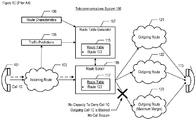
- Figure 1C depicts a more detailed schematic diagram of a portion of telecommunications system 100 depicted in Figure 1A , including call 1C being blocked and not reaching destination 113.
- Figure 1C additionally depicts: call 1C originating at call origin 101, a call attempt at the ingress to route server 109, route 123 lacking capacity to carry call 1C, and consequently, call 1C being blocked at the egress from route server 109.
- table 115/117 comprises only route 123 for destination 113.
- call 1C comes into route server 109 as a call attempt.
- Route server 109 receives call 1C and applies operative route table 117; route 123 is the only allowed route to be used during the present time period according to route table 117. However, the facilities of route 123 are not available to carry call 1C (e.g., because the facilities are all busy with other calls or are down for maintenance, etc.).
- Route server 109 is constrained in only having route 123 populated in route table 117, and when route 123 is not available, route server 109 blocks outgoing call 1C. No call seizure occurs. The caller who originated call 1C must try again.
- blocked calls are a substantial disadvantage in this scheme.
- margin-maximizing schemes like the one described above fail to consider other routes that have lower profit margins but are still cost-competitive. Further, the following documents may be considered as disclosing the background art.
- US 2003/012356 A1 discloses a distributed monitoring, evaluation and routing (“DiMER") system capable of active management of data network-based telephony.
- DIMER distributed monitoring, evaluation and routing
- Such a system, and data network-based telephony incorporating the same routes calls to meet call quality standards, connection speed and/or cost goals, among other targets.
- the system incorporates preferences with periodically obtained call-related data and analysis, and revises call routing, as appropriate, by shifting or reallocating call traffic between available terminating gateways (based on their performance and caller preferences).
- EP 0 863 681 A2 discloses routing of calls from one network to another network by tracking the call completion history over each trunk group connecting the networks. From a knowledge of the call completion history for each route, a Completion Rate Factor (CRF), representing the ratio of completed calls to all calls attempted is computed. The route having the CRF representing the highest number of completions is then selected. Typically, the process is dynamic, so that if the selected route no longer has the highest number of completions, then the route previously found to have the highest number of call completions is selected.
- CRF Completion Rate Factor
- the concept of completion rate factor routing can be extended to multiple carriers to yield a carrier completion rate feature routing technique. Routing may also be completed in accordance with network congestion to route advance a call.
- CA 2 511 382 A1 discloses a method for selecting routes in a circuit-switched network such that multiple requests to create a circuit are distributed efficiently among a plurality of routes each having different characteristics. For each request, candidate routes are first selected using coarse criteria, they are then sorted using a probabilistic algorithm. Each route is then tried sequentially until the circuit has successfully bee n created. Further, the results of the efforts to create the circuit, and the measured characteristics of successfully created circuits are used as parameters in subsequent route selection decisions.
- EP 2 224 650 A1 discloses a method and corresponding apparatus to evaluate quality and to correct bias by determining a standard that accounts for at least one source of bias, comparing an observed measure of a provider against the standard to produce an evaluation of the observed measure of the provider, and making a decision about the quality of the provider based on the evaluation.
- US 2007/195700 A1 discloses a routing control method that includes: reading out predicted utilization transition data (e.g. utilization rate, or utilized bandwidth) associated with a received connection set-up request from a predicted utilization transition data storage storing said predicted utilization transition data for each resource (e.g. links between routers, or server) in a network in future; and selecting a resource satisfying a predetermined condition based on the read predicted utilization transition data.
- predicted utilization transition data e.g. utilization rate, or utilized bandwidth
- the problem relates to successfully routing more calls.
- This problem is solved by the features disclosed by the independent claims. Further exemplary embodiments are defined by the dependent claims.
- the present inventors devised certain quality considerations that are blended into generating a route table to overcome some of the disadvantages of the prior art. Because call blocking is disadvantageous, expanding the number of route choices would be desirable, but risks damaging the operator's profitability when the added routes are not cost-effective. On the other hand, lowest-cost routes sometimes are plagued by quality problems such as poor voice quality, unavailability, unreliability, dropped calls, etc. Thus, merely adding more lowest-cost routes will not address the problems that arise in the prior art. The present inventors devised a system and method for blending particular quality considerations into the process of expanding the route choices in a route table, such that more calls can be successfully routed while retaining the operator's objective of maximizing profitability.
- the disclosed quality auto-blending techniques evaluate candidate outgoing routes based on specific quality metrics to determine (i) whether a new route should be chosen for a route table and (ii) how call volumes are to be allocated among the chosen routes, so that overall profitability can be maximized within the governing constraints of quality targets, route quality, predicted traffic, and route capacity. It will be understood by those having ordinary skill in the art, after reading the present disclosure, that any reference herein to a route also includes any devices or facilities that carry traffic into and out of the disclosed route server.
- An illustrative telecommunications system comprises an enhanced route table generator and an enhanced route server.
- the route table generator generates a route table that is to direct the route server how to route calls during a given period of time, e.g., during the upcoming hour.
- the route table generator transmits the route table to the route server.
- the route server routes incoming call attempts based on the route choices and call allocations specified in the route table.
- the route table generator iteratively generates and adapts a route table until no further optimization can be found.
- the route table generator maximizes a profitability objective while expanding the pool of suitable routes in the route table based in part on quality targets.
- Some routes in the route table are allocated larger call volumes while other routes are allocated lower call volumes based in part on the quality metrics that are defined herein:
- the enhanced route table generator illustratively executes a linear programming run that generates an initial route table that maximizes a profitability metric for the predicted traffic for the given time period based at least in part on (i) a first threshold value of the ASR quality metric for the predicted traffic, wherein the ASR quality metric is based on a ratio of answered calls to call seizures, and (ii) the predicted traffic for the given time period.
- the resulting initial route table maximizes the objective subject to the established constraints and comprises at least one route chosen from the candidate routes such that at least some of the predicted traffic is allocated to the chosen route(s).
- the route table generator When the initial route table is evaluated against several criteria, including a target threshold value for the ACD quality metric, and is deemed not optimal by the route table generator, one or more linear programming runs are executed iteratively until an adapted route table is generated that is deemed optimal. In the course of the iterative route table generation, the ASR and ACD target thresholds are successively relaxed.
- Each route table generated in a subsequent linear programming run maximizes a profitability metric for the predicted traffic for the given time period based at least in part on (i) a relaxed threshold value of the ASR quality metric for the predicted traffic, wherein the ASR quality metric is based on a ratio of answered calls to call seizures, (ii) the predicted traffic for the given time period, and (iii) a relaxed threshold value of the ACD quality metric for the predicted traffic, wherein the ACD quality metric measures call duration per answered call for the given time period.
- the quality considerations are auto-blended into the route generation process, and they affect which routes are chosen and how big of a traffic allocation they are given so that profitability can be maximized to the extent possible.
- the resultant call routing is based on (A) the ASR quality metric and (B) the ACD quality metric.
- An illustrative method comprises:
- An illustrative system comprises:
- Another illustrative method comprises:
- FIG. 2A depicts a schematic diagram of some salient elements of telecommunications system 200 (with quality blending) according to an illustrative embodiment of the present invention, and depicts call 2A routed via route 121 and answered at destination 113.
- Telecommunications system 200 comprises: quality targets 201, traffic predictions 205, route characteristics 206, enhanced route table generator 207 (comprising route table 215), and enhanced route server 209 (comprising route table 217).
- Figure 2A additionally depicts: call origin 101, incoming route 103, outgoing routes 121, 122, and 123, and call destination 113, which are connected to telecommunications system 200 as shown, but which are not components of telecommunications system 200 and which were described above and will not be repeated here for the sake of brevity.
- Figure 2A further depicts: call 2A originating at call origin 101, a call attempt at the ingress to enhanced route server 209, a call seizure at the egress from enhanced route server 209 via outgoing route 121, and an answered call at destination 113.
- Figure 2A also indicates that according to at least one relevant quality metric in respect to outgoing routes 121, 122, and 123, the quality of route 121 exceeds the quality of route 122 which exceeds the quality of route 123.
- these quality metrics were not considered in the prior-art schemes described in reference to figures 1A , 1B , and 1C .
- the illustrative embodiment of the present invention takes into consideration one or more route-quality metrics when enhanced route table generator 207 generates route table 215 - the illustrative techniques are referred to herein as "quality blending" (or “quality auto-blending") and involve the ASR and ACD quality metrics.
- quality blending or “quality auto-blending”
- the quality metrics and quality blending techniques are described in more detail below and in the accompanying figures.
- Quality targets 201 are stored in one or more data structures and comprise performance targets to be applied in generating route table 215. According to the illustrative embodiment, quality targets 201 comprise (i) a first threshold for the answer-seizure ratio quality metric ("ASR"), and (ii) a second threshold for the answered-call duration quality metric ("ACD"). The quality targets 201 reflect aspirational levels of call-routing performance for a given time interval and will be discussed in more detail below and in the accompanying figures.
- ASR answer-seizure ratio quality metric
- ACD answered-call duration quality metric
- quality targets 201 are stored in a data structure of a component external to enhanced route table generator 207; however, it will be clear to those having ordinary skill in the art, after reading the present disclosure, how to make and use alternative embodiments wherein quality targets 201 are stored within enhanced route table generator 207, etc., without limitation.
- Traffic predictions 205 which are well known in the art, are stored in one or more data structures and comprise predicted telecommunications traffic data for one or more periods of time, for one or more destinations.
- traffic predictions 205 comprise, per destination in a given period of time, the number of predicted calls and the expected per-call duration.
- a feedback path (not shown) from enhanced route server 209 provides historical call duration information for traffic predictions 205.
- traffic predictions 205 are generated and stored in a data structure of a component external to enhanced route table generator 207; however, it will be clear to those having ordinary skill in the art, after reading the present disclosure, how to make and use alternative embodiments wherein traffic predictions 205 are stored within enhanced route table generator 207, etc., without limitation.
- Route characteristics 206 are stored in one or more data structures, and comprise information about any facilities and outgoing routes emanating from enhanced route server 209, e.g., routes 121, 122, and 123.
- route characteristics 206 comprise: the capacity of each outgoing route and/or outgoing facility emanating from enhanced route server 209 typically measured in calling minutes available per hour; historical information about the routes/facilities, such as maintenance periods when a facility or route might be completely unavailable; and other historical performance data such as failure rates that measure the reliability of the route/facility.
- a feedback path (not shown) from enhanced route server 209 provides historical information to route characteristics 206.
- route characteristics 206 are generated and stored in a data structure of a component external to enhanced route table generator 207; however, it will be clear to those having ordinary skill in the art, after reading the present disclosure, how to make and use alternative embodiments wherein route characteristics 206 are stored within enhanced route table generator 207, etc., without limitation.
- Enhanced route table generator 207 (or “table generator 207"), coordinates and executes the operations of method 400 herein, and is described in further detail below and in the accompanying figures.
- Enhanced route server 209 (or “route server 209"), coordinates and executes the operations of method 1100 herein, and is described in more detail below and in the accompanying figures.
- route server 209 is responsible for handling a call, i.e., processing a call arriving from an incoming route and placing it on an available outgoing route or corresponding facility (if any), but route server 209 is not responsible for handling the call after egress from the route server.
- Route table 215/217 comprises routes 121, 122, and 123 for destination 113; however, it will be clear to those having ordinary skill in the art, after reading the present disclosure, how to make and use alternative embodiments wherein the route table comprises any number of outgoing routes according to the disclosed methods herein.
- enhanced route table generator 207 and enhanced route server 209 are distinct components of telecommunications system 200.
- enhanced route table generator 207 and enhanced route server 209 are co-resident on the same hardware platform, or form a single integrated component, or are otherwise combined.
- elements 201, 206, 205, 207, and 209 are embodied in a single multi-functional integral component, or are differently combined or sub-divided than shown herein.
- the present figure depicts only one call origin 101, one incoming call 2A, and one incoming route 103, it will be clear to those having ordinary skill in the art, after reading the present disclosure, how to make alternative embodiments of telecommunications system 200 with any number of call origins, any number of incoming call attempts, and any number of incoming routes.
- the present figure depicts only three outgoing routes and only one destination 113, it will be clear to those having ordinary skill in the art, after reading the present disclosure, how to make alternative embodiments of telecommunications system 200 with any number of outgoing routes and any number of destinations. Further, it will be clear to those having ordinary skill in the art, after reading the present disclosure, how to make alternative embodiments wherein the relative quality of the outgoing routes is different than depicted here.
- Figure 2B depicts a schematic diagram of some salient elements of telecommunications system 200 (with quality blending) according to the illustrative embodiment of the present invention, and illustrating call 2A routed via route 123 and answered at destination 113.
- Figure 2B depicts the same elements depicted in Figure 2A , except that outgoing routes 121 and 122 are unavailable here (e.g., all busy, down for maintenance, etc.) and call 2B is routed by enhanced route server 209 to outgoing route 123.
- the quality (according to the ASR and/or ACD quality metrics) of route 123 is lower than the respective quality of the unavailable routes 121 and 122
- route table 217 includes route 123 and therefore call 2B is not blocked.
- FIG. 3A depicts a schematic diagram of the hardware platform for enhanced route table generator 207 according to the illustrative embodiment.
- enhanced route table generator 207 is based on a data-processing apparatus whose hardware platform comprises: processor 301, memory 302, transmitter 303 and receiver 304.
- Processor 301 is a processing device such as a microprocessor that is well known in the art. Processor 301 is configured such that, when operating in conjunction with the other components of route table generator 207, processor 301 executes software, processes data, and telecommunicates according to the operations described herein.
- Memory 302 is non transitory and non volatile computer storage memory technology that is well known in the art, e.g., flash, RAM, etc.
- Memory 302 stores operating system 311, application software 312, element 313, and element 314.
- the specialized application software 312 that is executed by processor 301 is illustratively denominated the "quality auto-blend logic" that enables enhanced route table generator 207 to perform the operations of method 400.
- Memory element 313 illustratively comprises received quality targets (e.g., from quality targets 201), traffic predictions (e.g., from traffic predictions 205), route characteristics and historical performance data (e.g., from route characteristics 206).
- Memory element 313 also comprises other data, records, results, lists, associations, indicators, whether of an intermediate nature, final results, or archival.
- the generated routing table(s) (e.g., route table 215) that is to be transmitted to enhanced route server 209 is illustratively stored in memory element 314. It will be clear to those having ordinary skill in the art how to make and use alternative embodiments that comprise more than one memory 302; or comprise subdivided segments of memory 302; or comprise a plurality of memory technologies that collectively store operating system 311, application software 312, and elements 313 and 314.
- Transmitter 303 is a component that enables route table generator 207 to telecommunicate with other components and systems by transmitting electromagnetic signals thereto.
- transmitter 303 enables telecommunication pathways to quality targets 201, traffic predictions 205, route characteristics 206, enhanced route server 209, other systems (not shown), display(s) (not shown), etc. without limitation.
- Transmitter 303 is well known in the art. It will be clear to those having ordinary skill in the art how to make and use alternative embodiments that comprise more than one transmitter 303.
- Transmitter 303 is shown in a wired configuration, but in some alternative embodiments, transmitter 303 may telecommunicate wirelessly.
- Receiver 304 is a component that enables route table generator 207 to telecommunicate with other components and systems by receiving electromagnetic signals therefrom.
- receiver 304 enables telecommunication pathways from quality targets 201, traffic predictions 205, route characteristics 206, enhanced route server 209, other systems (not shown), display(s) (not shown), etc. without limitation.
- Receiver 304 is well known in the art. It will be clear to those having ordinary skill in the art how to make and use alternative embodiments that comprise more than one receiver 304.
- Receiver 304 is shown in a wired configuration, but in some alternative embodiments, receiver 304 may telecommunicate wirelessly.
- route table generator 207 can be embodied as a multi-processor platform, as a sub-component of a larger computing platform, as a virtual computing element, or in some other computing environment - all within the scope of the present invention. It will be clear to those skilled in the art, after reading the present disclosure, how to make and use the hardware platform for route table generator 207.
- FIG. 3B depicts a schematic diagram of the hardware platform for enhanced route server 209 according to the illustrative embodiment.
- enhanced route server 209 is a data-processing apparatus whose hardware platform comprises: processor 351, memory 352, transmitter 353 and receiver 354.
- Processor 351 is a processing device such as a microprocessor that is well known in the art. Processor 351 is configured such that, when operating in conjunction with the other components of route server 209, processor 351 executes software, processes data (including the processing of calls), and telecommunicates according to the operations described herein.
- Memory 352 is non transitory and non volatile computer storage memory technology that is well known in the art, e.g., flash, RAM, etc.
- Memory 352 stores operating system 361, application software 362, element 363, and element 364.
- the specialized application software 362 that is executed by processor 351 is illustratively denominated the "call routing logic" that enables route server 209 to perform the operations of method 1100.
- Memory element 363 illustratively comprises call routing statistics collected by route server 209, as well as other data, records, results, lists, associations, indicators, whether of an intermediate nature, final results, or archival.
- the operative routing table(s) e.g., route table 217) that is the basis for routing calls is illustratively stored in memory element 364.
- Transmitter 353 is a component that enables route server 209 to telecommunicate with other components and systems by transmitting electromagnetic signals thereto.
- transmitter 303 enables telecommunication pathways to enhanced route table generator 207, incoming routes (e.g., 103), outgoing routes (e.g., 121, 122, 123), other systems (not shown), display(s) (not shown), etc. without limitation.
- Transmitter 353 is well known in the art. It will be clear to those having ordinary skill in the art how to make and use alternative embodiments that comprise more than one transmitter 353.
- Transmitter 353 is shown in a wired configuration, but in some alternative embodiments, transmitter 353 may telecommunicate wirelessly.
- Receiver 354 is a component that enables route server 209 to telecommunicate with other components and systems by receiving electromagnetic signals therefrom.
- receiver 354 enables telecommunication pathways from enhanced route table generator 207, incoming routes (e.g., 103), outgoing routes (e.g., 121, 122, 123), other systems (not shown), display(s) (not shown), etc. without limitation.
- Receiver 354 is well known in the art. It will be clear to those having ordinary skill in the art how to make and use alternative embodiments that comprise more than one receiver 354.
- Receiver 354 is shown in a wired configuration, but in some alternative embodiments, receiver 354 may telecommunicate wirelessly.
- route server 209 can be embodied as a multi-processor platform, as a sub-component of a larger computing platform, as a virtual computing element, or in some other computing environment - all within the scope of the present invention. It will be clear to those skilled in the art, after reading the present disclosure, how to make and use the hardware platform for route server 209.
- Route table generator 207 is the entity within illustrative telecommunications system 200 that executes and coordinates the operations of method 400 according to the illustrative embodiment of the quality auto-blend logic.
- route table generator 207 receives one or more quality targets for a given time period, e.g., for the upcoming hour. Operation 401 is described in more detail below and in the accompanying figures.
- route table generator 207 receives route characteristics that include illustratively costs, margins, capacity, historical data, and performance data for each route that emanates from route server 209.
- route table generator 207 receives route characteristics 206.
- the routes that emanate from route server 209 that are potential candidates for routing a call to a given destination are designated herein as "candidate" routes.
- candidate routes are evaluated in subsequent operations and some are chosen for the route table.
- route table generator 207 receives traffic predictions for the given time period.
- the traffic predictions illustratively comprise traffic corresponding to a plurality of destinations that are served by telecommunications system 200.
- route table generator 207 receives traffic predictions 205 for the given time period.
- route table generator 207 generates one or more route tables based on the quality targets, the route characteristics, and traffic predictions received in the preceding operations. Operation 407 is described in more detail below and in the accompanying figures.
- route table generator 207 transmits the generated route table(s) (designated "optimal") to route server 209.
- route server 209 routes incoming calls according to the route table(s) received from route table generator 207.
- route table generator 207 transmits information to other systems, and to any relevant displays, and archives as appropriate - according to transmission techniques that are well known in the art.
- route table generator 207 passes control back to operation 401 to repeat the aforementioned operations for the next applicable time period, e.g., the hour that follows the present given time period.
- next applicable time period e.g., the hour that follows the present given time period.
- method 400 it will be clear to those having ordinary skill in the art, after reading the present disclosure, how to make and use alternative embodiments of method 400 wherein the recited operations and sub-operations are differently sequenced, grouped, or sub-divided - all within the scope of the present invention. It will be further clear to those skilled in the art, after reading the present disclosure, how to make and use alternative embodiments of method 400 wherein some of the recited operations and sub-operations are optional, are omitted, or are executed by other elements and/or systems, e.g., by route server 209 or by a unified element that both generates the route tables and routes call according thereto.
- Figure 5 depicts some salient sub-operations of operation 401 according to the illustrative embodiment.
- route table generator 207 receives a first threshold for a first quality metric, e.g., for the answer-seizure ratio ASR metric; the threshold represents a quality target for routing calls to a destination during the given time period.
- the target ASR threshold is 100%, meaning that the target is to have 100% of seized calls reach their destination and be answered.
- route table generator 207 receives a second threshold for a second quality metric, e.g., for the answered-call duration ACD metric; the threshold represents a quality target for routing calls to the destination during the given time period.
- the target ACD threshold is 10 minutes, meaning that the target is to have a 10-minute call duration per call routed during the given time period.
- route table generator 207 receives a first decrement value to apply to the first threshold to lower (or relax) the quality target for the first quality metric.
- the first decrement is 10%, meaning that if it becomes necessary to relax the ASR target (as described in further detail below), the decrease will be in 10% decrements, i.e., from 100% ASR to 90% ASR to 81% ASR, etc.
- route table generator 207 receives a second decrement value to apply to the second threshold to lower (or relax) the quality target for the second quality metric.
- the second threshold is also 10%, meaning that if it becomes necessary to relax the ACD target (as described in further detail below), the decrease will be in 10% decrements, i.e., from 10 minutes-per-call ACD to 9 minutes to 8.1 minutes, etc.
- route table generator 207 passes control back to operation 501 to repeat the aforementioned operations for another destination having predicted traffic, or for other outgoing routes, as appropriate.
- control passes to operation 403.
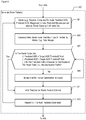
- Figure 6 depicts some salient sub-operations of operation 407 according to the illustrative embodiment.
- route table generator 207 obtains (for example, by receiving from another entity, or by computing locally) a predicted ASR value for each candidate route.
- route table generator 207 computes a predicted ASR value for each candidate route based on historical data and performance metrics from earlier time periods, e.g., a baseline same hour of the day on the same year-ago day of week as the given period of time. Thus, for the relevant baseline time period on a given candidate route, route table generator 207 computes the ratio of answered calls to seized calls. This value is used as the predicted ASR.
- route table generator 207 also obtains a predicted ACD value for each candidate route, a predicted minutes-per-call-attempt value for each candidate route, and a capacity value for each candidate route (illustratively in minutes available for the given period of time).
- route table generator 207 computes the predicted ACD for each candidate route based on historical data and performance metrics from earlier time periods, e.g., a baseline same hour of the day on the same year-ago day of week as the given period of time.
- route table generator 207 also obtains a predicted minutes-per-call-attempt value for each candidate route.
- route table generator 207 computes the predicted minutes-per-call-attempt value for each candidate route based on historical data, measuring the ratio of the number of minutes a call was connected on the route to the number of call attempts during the baseline time period. It will be clear to those having ordinary skill in the art, after reading the present disclosure, how to make and use alternative embodiments based on one or more of the following baseline historical time periods: last-hour today, same-hour yesterday, same-hour in past weeks, special days such as Mother's Day, etc. without limitations. The choice of an appropriate baseline time period is left to the implementers practicing the present invention.
- route table generator 207 also obtains a capacity value for each candidate route, illustratively in minutes available for the given period of time.
- the baseline is illustratively the same hour of the day on the same year-ago day of week as the given period of time.
- other schemes could be devised, such as a daily hourly average from the previous day, or year-ago data that is modulated by a recent performance improvement in the facilities of a given route, etc.
- it will be up to the implementers to choose one or more baseline time periods and supporting baseline data for obtaining the metrics specified in the present operation.
- route table generator 207 generates an initial route table that maximizes a predefined profitability metric.
- the profitability metric to be optimized is a total margin value encompassing all the allocated calls during the given time period according to the route table.
- route table generator 207 uses linear programming to process several constraints and maximize the total margin. The present operation is described in more detail below and in the accompanying figures.
- route table generator 207 analyzes whether, according to the generated route table:
- route table generator 207 iterates until no further route table optimization is found. When no further optimization is found, control passes to operation 611; otherwise, control passes back to operation 607.. Operation 609 is described in further detail below and in the accompanying figures.
- route table generator 207 Infers that the current extant route table is optimal and passes control to operation 613.
- route table generator 207 repeats the cycle of operations for a next predicted destination for the given period of time; thus, for example, if the traffic predictions 205 predict traffic to ten distinct destinations for the given time period, operation 407 including its constituent sub-operations is executed for each of the ten distinct destinations. Then, control passes from operation 407 to operation 409. It will be clear to those having ordinary skill in the art, after reading the present disclosure, how to make and use alternative embodiments of the present invention wherein operation 407 is executed once for several or even all of the contemplated destinations of the predicted traffic, such that the repetitive loop illustrated by operation 613 is eliminated in whole or in part. This unified approach would tend to reduce the overall processing time of generating the route table.
- Figure 7 depicts some salient sub-operations of operation 605 according to the illustrative embodiment. Because the illustrative embodiment generates a route table based on linear programming techniques, the present operation accordingly establishes the objective(s) to be maximized and the relevant constraints (including the ASR quality metric and its supporting data) to apply to the execution of the linear programming run.
- the initial route table maximizes a profitability metric for the predicted traffic based at least in part on (i) the first threshold value of the ASR quality metric for the predicted traffic, wherein the ASR quality metric is based on a ratio of answered calls to call seizures, (ii) the predicted traffic, and (iii) the second threshold value of the ACD quality metric for the predicted traffic, wherein the ACD quality metric measures call duration per answered call.
- route table generator 207 establishes the objective to be maximized, illustratively a profitability metric.
- the profitability metric to be optimized is a total margin value encompassing all the allocated calls according to the route table, i.e., the per-route margin-per-minute value multiplied by the total number of call-minutes allocated to the respective route.
- the profitability metric to be optimized is a total margin value encompassing all the allocated calls according to the route table, i.e., the per-route margin-per-minute value multiplied by the total number of call-minutes allocated to the respective route.
- the profitability metric to be optimized is a total margin value encompassing all the allocated calls according to the route table, i.e., the per-route margin-per-minute value multiplied by the total number of call-minutes allocated to the respective route.
- to maximize the total margin it is preferable to allocate more call-minutes to high-margin routes and fewer calls to lower-margin routes, though, as explained, there are quality
- route table generator 207 establishes one or more quality constraints. Illustratively, route table generator 207 establishes the first threshold of the ASR quality metric as a constraint here.
- route table generator 207 establishes one or more traffic constraints. Illustratively, route table generator 207 establishes the predicted traffic for each distinct destination for the given time period, e.g., 1500 calls to destination A during hour 0900, and 2000 calls to destination B during the same hour 900.
- route table generator 207 identifies the routes and/or the corresponding suppliers' telecommunication facilities that are candidates for the predicted traffic, e.g., routes 121-123 and 1021-1023 respectively.
- route table generator 207 establishes one or more call-carrying capacity constraints for each of the candidate routes, e.g., 150 call-minutes for route 121, 200 call-minutes for route 122, etc.
- the units are in call-minutes, though other units can be used as the implementers see fit.
- the call-carrying capacity figures are obtained from historical data as explained earlier.
- route table generator 207 obtains, for each candidate route, a cost characteristic and/or a profitability characteristic, such as a margin-per-call-minute value. Illustratively, route table generator 207 obtains a per-route margin-dollar-per-call-minute value for each candidate route.
- route table generator 207 executes a linear programming run that generates the route table based on the objective and subject to the constraints above; the resulting initial route table maximizes the objective and comprises at least one route chosen from the candidate routes to a destination such that at least some of the predicted traffic is allocated to the chosen route(s).
- Figure 10A depicts an initial route table 1001 that comprises routes to destinations A and B. Notably, according to table 1001 generated under the existing objective and constraints, some of the predicted traffic to destination A could not be allocated to a route (50 call attempts), and likewise, some of the predicted traffic to destination B also could not be allocated to a route (900 call attempts). Control passes out of operation 605 to operation 607.
- Figure 8 depicts some salient sub-operations of operation 609 according to the illustrative embodiment.
- route table generator 207 identifies, from among the routes in the route table, those routes that have a predicted ACD value that exceeds the target ACD threshold currently in effect - any such route is designated a "retained" route.
- route table generator 207 calculates a measure of "excess predicted traffic,” which is defined as the difference between the total predicted traffic for the given time period and the traffic that the route table has allocated to the retained route(s). Another way of looking at "excess predicted traffic” is that it comprises predicted traffic that (i) is either allocated to a route which falls short of the target ACD threshold or (ii) is unallocated in the route table.
- the "excess predicted traffic” is analyzed further below to determine whether by relaxing the governing quality metric targets, i.e., ASR and ACD thresholds, the route table can be adapted to yield improved results.
- route table generator 207 lowers the target ASR threshold by the first decrement value, illustratively decrementing 10% from 100%, resulting in a lowered target ASR threshold of 90% answer-seizure ratio. This operation relaxes the quality requirements for any non-retained routes that are candidates for the "excess predicted traffic.”
- route table generator 207 lowers the target ACD threshold by the second decrement value, illustratively decrementing 10% from 10 minutes, resulting in a lowered target ACD of 9 answered-call minutes. This operation relaxes the quality requirements for any non-retained routes that are candidates for the "excess predicted traffic.”
- route table generator 207 analyzes whether there any non-retained candidate routes that can carry some/all of the excess predicted traffic subject to the lowered ASR and the lowered ACD. This is determined by comparing the predicted ASR and the predicted ACD of a route against the lowered ASR and lowered ACD thresholds, respectively. When the answer is affirmative, route table generator 207 infers that the current route table can be adapted and control passes to operation 811. When the answer is negative, the present iterative operation (i.e., operation 609) ends and control passes out of operation 609 to operation 611 (where route table generator 207 infers that no further optimization of the current route table can be found).
- Figure 9 depicts some salient sub-operations of operation 811 according to the illustrative embodiment. Because the illustrative embodiment generates an adapted route table based on linear programming techniques, the present operation accordingly establishes the objective(s) to be maximized and the relevant constraints (including the quality metrics ASR and ACD and their supporting data) to apply to the execution of the linear programming run.
- the adapted route table maximizes a profitability metric for the predicted traffic based at least in part on (i) the lowered threshold value of the ASR quality metric for the predicted traffic, wherein the ASR quality metric is based on a ratio of answered calls to call seizures, (ii) the predicted traffic, and (iii) the lowered threshold value of the ACD quality metric for the predicted traffic, wherein the ACD quality metric measures call duration per answered call.
- route table generator 207 establishes the objective to be maximized, illustratively a profitability metric.
- the profitability metric to be optimized here is the same as the one in operation 701, which is a total margin value encompassing all the allocated calls during the given time period according to the route table, i.e., the per-route margin-per-minute value multiplied by the total number of call-minutes allocated to the respective route. It will be clear to those having ordinary skill in the art, after reading the present disclosure, how to make and use alternative embodiments that use a different maximization objective in operation 901 than used in operation 701.
- route table generator 207 establishes one or more quality constraints. Illustratively, route table generator 207 establishes the lowered threshold of the ASR quality metric, and also the lowered threshold of the ACD quality metric as constraints here.
- route table generator 207 establishes one or more traffic constraints. Illustratively, route table generator 207 establishes the "excess predicted traffic" for each distinct destination for the given time period as the constraint here.
- route table generator 207 identifies the non-retained routes and/or the corresponding suppliers' telecommunication facilities that are candidates for the "excess predicted traffic.”
- route table generator 207 establishes one or more call-carrying capacity constraints for each of the non-retained candidate routes. As before, the units are in call-minutes, though other units can be used as the implementers see fit. The call-carrying capacity figures are obtained from historical data as explained earlier.
- route table generator 207 obtains, for each non-retained candidate route, a cost characteristic and/or a profitability characteristic, such as a margin-per-call-minute value. Illustratively, route table generator 207 obtains a per-route margin-dollar-per-call-minute value for each non-retained candidate route.
- route table generator 207 executes a linear programming run that generates the route table based on the objective and subject to the present constraints; the resulting adapted route table comprises (i) the retained routes, and (ii) at least one other route that satisfies the lowered quality threshold constraints, allocating some/all of the predicted excess traffic to the at least one other route.
- Figure 10B depicts an adapted route table 1002 that comprises routes to destinations A and B. Notably, according to table 1002 generated under the present objective and more relaxed quality constraints, all the predicted traffic for the given time period has been allocated and no unallocated traffic remains.
- route table 1001 in Figure 10A has been adapted, based on relaxed quality constraints to have more routes that have sufficient call-carrying capacity for all the predicted traffic in the given time period. Notably, this is an iterative process that might require repeated iterations of operation 811 to successively relax the quality constraints and incrementally add more routes to carry the excess predicted traffic (or as much of it as feasible under the totality of constraints).
- the adapted table 1002 is an improvement over initial table 1001. Control passes from operation 811 to operation 607.
- Figure 10A depicts an illustrative initial route table 1001 generated according to operation 605 of the illustrative embodiment. The present figure was also discussed above in paragraphs [00102] and [00117].
- Table 1001 comprises columns 1011, 1012, 1013, and 1014.
- Column 1011 lists the distinct destinations for the given period of time. Destination identifiers are well known in the art. Here, destinations A and B are depicted.
- Column 1012 lists the route identifier or some corresponding supplier facility that can carry calls. Here, outgoing routes 121, 122, 1021, and 1022 are depicted.
- Column 1013 lists the number of predicted call attempts allocated to each destination-route pair. Here, 750 call attempts are allocated to route 121 for destination A, 700 call attempts are allocated to route 122 for destination A, 1000 call attempts are allocated to route 1021 for destination B, and 100 call attempts are allocated to route 1022 for destination B.
- Column 1014 lists the number of predicted call attempts for a destination that remain unallocated to an outgoing route. Here, 50 calls remain unallocated for destination A, and 900 calls remain unallocated for destination B.
- Figure 10B depicts an illustrative adapted route table 1002 generated according to operation 811 of the illustrative embodiment. The present figure was discussed in more detail in paragraph [00117] above.
- Table 1002 comprises columns 1011, 1012, 1013, and 1014.
- Column 1011 lists the distinct destinations for the given period of time. Here, destinations A and B are depicted.
- Column 1012 lists the route identifier or some other supplier facility that can carry calls. Here, outgoing routes 121, 122, 123, 1021, 1022, and 1023 are depicted.
- Column 1013 lists the number of predicted call attempts allocated to each destination-route pair.
- 750 call attempts are allocated to route 121 for destination A (same as in table 1001)
- 700 call attempts are allocated to route 122 for destination A (same as in table 1001)
- 50 call attempts are allocated to route 123 for destination A
- 1000 call attempts are allocated to route 1021 for destination B (same as in table 1001)
- 100 call attempts are allocated to route 1022 for destination B (same as in table 1001)
- 900 calls are allocated to route 1023 for destination B.
- Column 1014 lists the number of predicted call attempts for a destination that remain unallocated to an outgoing route. Here, there are no unallocated predicted call attempts.
- the present table 1002 illustrates how the illustrative embodiment successfully blended particular quality considerations into the process of expanding the route choices in a route table, such that more calls can be successfully routed, subject to quality requirements, while retaining the operator's objective of maximizing profitability. As compared to table 1001, table 1002 allocates all predicted traffic. 950 more calls are allocated in table 1002 as compared to table 1001.
- the profitability of handling more calls is also improved, even if some of the routes in table 1002 have a lower margin than the originally-chosen routes in table 1001.
- the margin-per-minute value for outgoing route 123 is lower than for routes 121 and 122
- the margin-per-minute value for outgoing route 1023 is lower than for routes 1021 and 1022; even so, these lower-margin routes have been auto-blended into the route table 1002 according to the illustrative ASR and ACD analysis.
- Figure 11 depicts some salient operations of method 1100 according to the illustrative embodiment.
- Route server 209 is the entity within illustrative telecommunications system 200 that executes and coordinates the operations of method 1100 according to the illustrative embodiment of the call routing logic. Accordingly, telecommunications system 200 is responsible for both method 400 and method 1100. It will be clear to those having ordinary skill in the art, after reading the present invention, how to make and use alternative embodiments of the present invention wherein one unified apparatus comprises the functionality of route table generator 207 and route server 209, including the functionality of the quality auto-blend logic and the call routing logic; in such a unified embodiment, data is transferred internally.
- route server 209 receives one or more route tables from route table generator 207, for one or more time periods wherein the respective route tables are to be in effect.
- route server 209 receives route table 215 from route table generator 207.
- route server 209 established the received route table at the appropriate time as the operative route table for the applicable time period.
- route server 209 establishes the contents of route table 215 as the operative route table 217.
- route server 209 routes calls according to route table 217.
- route server 209 places the call on an outgoing route as specified by route table 217 and the respective call allocations in route table 217.
- the call allocations in the route table guide how actual calls are routed to which route in order to maintain the relative allocations in the route table. Because the route table is based on the ASR and ACD quality metrics as described in detail above, when the route server applies the route table to the processing of actual calls, the routing of calls is likewise based on the ASR and ACD quality metrics.
- route server 209 collects data about the ongoing traffic into and out of route server 209, optionally performs statistical analysis on the collected data, transmits the raw data and the statistical analysis to other systems (e.g., traffic predictors, route characterizers, route table generator 207, etc.), and also optionally archives the data for further retrieval and analysis.
- systems e.g., traffic predictors, route characterizers, route table generator 207, etc.
- route server 209 repeats the above-enumerated sub-operations for the next applicable time period, e.g., the 1000 hour.
- method 1100 it will be clear to those having ordinary skill in the art, after reading the present disclosure, how to make and use alternative embodiments of method 1100 wherein the recited operations and sub-operations are differently sequenced, grouped, or sub-divided - all within the scope of the present invention. It will be further clear to those skilled in the art, after reading the present disclosure, how to make and use alternative embodiments of method 1100 wherein some of the recited operations and sub-operations are optional, are omitted, or are executed by other elements and/or systems, e.g., by route table generator 207, or by a unified element that both generates the route tables and routes call according thereto.
- route table generator 207 e.g., a unified element that both generates the route tables and routes call according thereto.
Landscapes
- Engineering & Computer Science (AREA)
- Computer Networks & Wireless Communication (AREA)
- Signal Processing (AREA)
- Telephonic Communication Services (AREA)
Claims (8)
- Ein Verfahren, das Folgendes umfasst:Erzeugen, durch ein Telekommunikationssystem (200), einer anfänglichen Routingtabelle (215) für einen vorhergesagten Verkehr (205), wobei der vorhergesagte Verkehr (205) pro Ziel in einer gegebenen Zeitperiode die Anzahl der vorhergesagten Anrufe enthält, wobei das Erzeugen zumindest teilweise auf Folgendem basiert:(i) einem ersten Schwellenwert einer ersten Qualitätsmetrik für den vorhergesagten Verkehr (205), wobei die erste Qualitätsmetrik auf einem Verhältnis von beantworteten Anrufen zu Anrufversuchen basiert,(ii) einem zweiten Schwellenwert einer zweiten Qualitätsmetrik für den vorhergesagten Verkehr (205), wobei die zweite Qualitätsmetrik die Anrufdauer pro beantworteten Anruf misst, und(iii) dem vorhergesagten Verkehr (205);Routen bzw. Leiten, durch das Telekommunikationssystem (200), einer Vielzahl von Anrufen gemäß der anfänglichen Routingtabelle (215);Analysieren, durch das Telekommunikationssystem (200), ob eine erste, zweite oder dritte Bedingung vorliegt:wobei die erste Bedingung dann vorliegt, wenn die erste Qualitätsmetrik für den vorhergesagten Verkehr (205) den ersten Schwellenwert für jede Route in der anfänglichen Routingtabelle (215) überschreitet;wobei die zweite Bedingung dann vorliegt, wenn die zweite Qualitätsmetrik für den vorhergesagten Verkehr (205) den zweiten Schwellenwert für jede Route in der anfänglichen Routingtabelle (215) überschreitet; undwobei die dritte Bedingung dann vorliegt, wenn der vorhergesagte Verkehr für den gegebenen Zeitraum den Routen in der anfänglichen Routingtabelle zugewiesen wird;Erzeugen, durch das Telekommunikationssystem (200), basierend auf der Analyse der ersten, zweiten oder dritten Bedingung, einer angepassten Routingtabelle (811) durch Dekrementieren des ersten Schwellenwertes um einen ersten vorbestimmten Wert, und Dekrementieren des zweiten Schwellenwertes um einen zweiten vorbestimmten Wert; undRouten, durch das Telekommunikationssystem (200), einer weiteren Mehrzahl von Anrufen gemäß der angepassten Routingtabelle (811).
- Das Verfahren nach Anspruch 1, wobei das Erzeugen der anfänglichen Routingtabelle (215) ferner basiert auf (iv) einer Kapazitätscharakteristik für jeden der mehreren in Betracht kommenden Routen.
- Das Verfahren nach Anspruch 1, das ferner Folgendes umfasst:Empfangen, durch einen Routingtabellen-Generator (207) des Telekommunikationssystems (200), eines vorhergesagten Verkehrs;wobei die anfängliche Routingtabelle (215) für den vorhergesagten Verkehr (205) durch den Routingtabellen-Generator (207) erzeugt wird, undwobei das Erzeugen ferner auf einer Kapazitätscharakteristik für jede der Vielzahl von Routen basiert, die für die Beförderung des vorhergesagten Verkehrs (205) in Betracht kommen.
- Das Verfahren nach Anspruch 3, das ferner Folgendes umfasst:für jede Route in der anfänglichen Routingtabelle, Berechnen, durch den Routingtabellen-Generator (207), eines vorhergesagten Wertes der ersten Qualitätsmetrik, basierend auf der ersten Routingtabelle;für jede Strecke in der ersten Routingtabelle, Berechnen, durch den Routingtabellen-Generator (207), eines vorhergesagten Wertes einer zweiten Qualitätsmetrik, basierend auf der ersten Routingtabelle, wobei die zweite Qualitätsmetrik die Anrufdauer pro beantworteten Anruf misst;wenn (A) der vorhergesagte Wert der ersten Qualitätsmetrik für jede Route in der ersten Routingtabelle den ersten Schwellenwert überschreitet, und (B) der vorhergesagte Wert der zweiten Qualitätsmetrik für jede Route in der ersten Routingtabelle einen zweiten Schwellenwert für die zweite Qualitätsmetrik überschreitet, und (C) eine ausreichende Kapazität unter den Routen in der ersten Routingtabelle vorhanden ist, um den vorhergesagten Verkehr (205) zu befördern, Routen einer Vielzahl von Anrufen gemäß der ersten Routingtabelle durch einen Routing-Server (209) des Telekommunikationssystems (200).
- Das Verfahren nach Anspruch 1, das Folgendes ferner umfasst: das iterative Durchführen des Schritts des Analysierens der Bedingungen eins, zwei und drei und des Erzeugens einer angepassten Routingtabelle (811), durch das Telekommunikationssystem (200), bis jede der Bedingungen eins, zwei und drei als positiv bestimmt wird, bevor die Mehrzahl von Anrufen gemäß der angepassten Routingtabelle (811) geroutet wird.
- Das Verfahren nach Anspruch 1, wobei mindestens ein Teil des vorhergesagten Verkehrs in der anfänglichen Routingtabelle einer oder mehreren Routen zugewiesen wird, die aus einer Vielzahl von Routen ausgewählt werden, die für die Beförderung des vorhergesagten Verkehrs (205) in Betracht kommen.
- Ein System (200), das Folgendes umfasst:einen Routingtabellen-Generator (207), der so konfiguriert ist, dass er für einen vorhergesagten Verkehr (205) eine anfängliche Routingtabelle (215) und eine angepasste Routingtabelle (811) erzeugt, wobei der vorhergesagte Verkehr (205) pro Ziel in einer gegebenen Zeitspanne eine Anzahl vorhergesagter Anrufe enthält,wobei der Routingtabellen-Generator (207) so konfiguriert ist, dass er die anfängliche Routingtabelle (215) zumindest teilweise auf folgender Grundlage erzeugt:(i) einem ersten Schwellenwert einer ersten Qualitätsmetrik für den vorhergesagten Verkehr (205), wobei die erste Qualitätsmetrik auf einem Verhältnis von beantworteten Anrufen zu Anrufversuchen basiert,(ii) einem zweiten Schwellenwert einer zweiten Qualitätsmetrik für den vorhergesagten Verkehr (205), wobei die zweite Qualitätsmetrik die Anrufdauer pro beantworteten Anruf misst, und(iii) den vorhergesagten Verkehr (205); undwobei der Routingtabellen-Generator (207) so konfiguriert ist, dass er die angepasste Routingtabelle (811) auf folgender Grundlage erzeugt:(a) Analysieren, durch das Telekommunikationssystem (200), ob irgendeine der Bedingungen eins, zwei oder drei vorliegt:(i) wobei die erste Bedingung dann vorliegt, wenn die erste Qualitätsmetrik für den vorhergesagten Verkehr (205) den ersten Schwellenwert für jede Route in der anfänglichen Routingtabelle (215) überschreitet;(ii) wobei die zweite Bedingung dann vorliegt, wenn die zweite Qualitätsmetrik für den vorhergesagten Verkehr (205) den zweiten Schwellenwert für jede Route in der anfänglichen Routingtabelle (215) überschreitet; und(iii) wobei die dritte Bedingung dann vorliegt, wenn der vorhergesagte Verkehr für den gegebenen Zeitraum den Routen in der anfänglichen Routingtabelle zugewiesen wird; und(b) Erzeugen, durch das Telekommunikationssystem (200), basierend auf der Analyse der ersten, zweiten oder dritten Bedingung, der angepassten Routingtabelle (811) durch Dekrementieren des ersten Schwellenwertes um einen ersten vorbestimmten Wert, und Dekrementieren des zweiten Schwellenwertes um einen zweiten vorbestimmten Wert; undeinen Routing-Server (209), der so konfiguriert ist, dass er eine Vielzahl von Anrufen gemäß der anfänglichen Routingtabelle (215) und der angepassten Routingtabelle (811) routet.
- Das System nach Anspruch 7, wobei der Routingtabellen-Generator (207) ferner so konfiguriert ist, dass er die anfängliche Routingtabelle (215) auf der Grundlage (iv) einer Kapazitätscharakteristik für jeden der mehreren in Betracht kommenden Routen erzeugt.
Applications Claiming Priority (2)
| Application Number | Priority Date | Filing Date | Title |
|---|---|---|---|
| US13/770,103 US8787541B1 (en) | 2013-02-19 | 2013-02-19 | System and method for quality auto-blending in call routing |
| PCT/US2014/016805 WO2014130423A1 (en) | 2013-02-19 | 2014-02-18 | System and method for quality auto-blending in call routing |
Publications (3)
| Publication Number | Publication Date |
|---|---|
| EP2959671A1 EP2959671A1 (de) | 2015-12-30 |
| EP2959671A4 EP2959671A4 (de) | 2016-03-09 |
| EP2959671B1 true EP2959671B1 (de) | 2020-09-23 |
Family
ID=51177943
Family Applications (1)
| Application Number | Title | Priority Date | Filing Date |
|---|---|---|---|
| EP14753506.6A Active EP2959671B1 (de) | 2013-02-19 | 2014-02-18 | System und verfahren zur automatischen qualitätsmischung in einer rufumleitung |
Country Status (7)
| Country | Link |
|---|---|
| US (3) | US8787541B1 (de) |
| EP (1) | EP2959671B1 (de) |
| AU (1) | AU2014219123B2 (de) |
| CA (1) | CA2901550C (de) |
| SG (1) | SG11201506391XA (de) |
| WO (1) | WO2014130423A1 (de) |
| ZA (1) | ZA201506897B (de) |
Families Citing this family (2)
| Publication number | Priority date | Publication date | Assignee | Title |
|---|---|---|---|---|
| US8787541B1 (en) * | 2013-02-19 | 2014-07-22 | Tata Communications (America) Inc. | System and method for quality auto-blending in call routing |
| US11956381B1 (en) * | 2023-01-17 | 2024-04-09 | Avoxi, Inc. | Proactive telephone number monitoring based on answer seizure ratio |
Family Cites Families (13)
| Publication number | Priority date | Publication date | Assignee | Title |
|---|---|---|---|---|
| US6021191A (en) * | 1997-03-05 | 2000-02-01 | At&T Corp. | Automatic routing technique |
| US5999604A (en) * | 1998-03-03 | 1999-12-07 | Mci Communications Corporation | System and method for managing a telecommunications network by determining service impact |
| US7502458B2 (en) * | 1999-06-05 | 2009-03-10 | Itxc Ip Holdings S.A.R.L. | System and method for call routing through a data network |
| US7076036B1 (en) * | 2001-10-17 | 2006-07-11 | Sprint Communications Company L.P. | Traffic and capacity modeling process |
| US20070008894A1 (en) * | 2004-10-19 | 2007-01-11 | Idt Corporation | Telecommunications-based link monitoring system |
| US20060133282A1 (en) * | 2004-12-21 | 2006-06-22 | Nortel Networks Limited | Systems and methods for multipath routing |
| CA2511382A1 (en) * | 2005-07-12 | 2007-01-12 | Consultants Ars Informatica S.A.R.F | Method for probabilistic route selection in a circuit switched network |
| JP4606333B2 (ja) * | 2005-09-20 | 2011-01-05 | 富士通株式会社 | ルーティング制御方法 |
| US8355485B2 (en) * | 2006-08-21 | 2013-01-15 | Centurylink Intellectual Property Llc | System and method for reporting telecommunications utilization and forecasting |
| US20100149984A1 (en) * | 2008-12-13 | 2010-06-17 | Salil Kapoor | Self Dimensioning and optimization of telecom Network - SDAOTN |
| US8068410B2 (en) * | 2009-02-27 | 2011-11-29 | Ibasis, Inc. | Bias correction for scrubbing providers |
| US8463939B1 (en) * | 2012-01-24 | 2013-06-11 | Brian R. Galvin | System and method for optimized and distributed routing of interactions |
| US8787541B1 (en) * | 2013-02-19 | 2014-07-22 | Tata Communications (America) Inc. | System and method for quality auto-blending in call routing |
-
2013
- 2013-02-19 US US13/770,103 patent/US8787541B1/en active Active
-
2014
- 2014-02-18 EP EP14753506.6A patent/EP2959671B1/de active Active
- 2014-02-18 CA CA2901550A patent/CA2901550C/en active Active
- 2014-02-18 WO PCT/US2014/016805 patent/WO2014130423A1/en not_active Ceased
- 2014-02-18 SG SG11201506391XA patent/SG11201506391XA/en unknown
- 2014-02-18 AU AU2014219123A patent/AU2014219123B2/en active Active
- 2014-06-30 US US14/319,020 patent/US9077797B2/en active Active
-
2015
- 2015-07-06 US US14/791,521 patent/US9369571B2/en active Active
- 2015-09-17 ZA ZA2015/06897A patent/ZA201506897B/en unknown
Non-Patent Citations (1)
| Title |
|---|
| None * |
Also Published As
| Publication number | Publication date |
|---|---|
| US20150326735A1 (en) | 2015-11-12 |
| CA2901550A1 (en) | 2014-08-28 |
| ZA201506897B (en) | 2017-02-22 |
| EP2959671A1 (de) | 2015-12-30 |
| SG11201506391XA (en) | 2015-09-29 |
| US9077797B2 (en) | 2015-07-07 |
| EP2959671A4 (de) | 2016-03-09 |
| WO2014130423A1 (en) | 2014-08-28 |
| US9369571B2 (en) | 2016-06-14 |
| US8787541B1 (en) | 2014-07-22 |
| AU2014219123A1 (en) | 2015-09-03 |
| US20140314224A1 (en) | 2014-10-23 |
| AU2014219123B2 (en) | 2017-05-18 |
| CA2901550C (en) | 2018-11-06 |
Similar Documents
| Publication | Publication Date | Title |
|---|---|---|
| JP4130301B2 (ja) | マルチスキルエージェント環境において、コールセンターエージェントの作業時間を自動的に予測するシステム | |
| US8761380B2 (en) | Adaptive estimated wait time predictor | |
| US6484145B1 (en) | Priority access channel reservation | |
| US8848887B2 (en) | Jurisdictionally optimized call routing | |
| US7502458B2 (en) | System and method for call routing through a data network | |
| US20150016600A1 (en) | Tiered call routing | |
| EP3605950B1 (de) | System zur selbstzuweisung von ressourcen | |
| US8189761B2 (en) | Method and system for managing calls | |
| US9369571B2 (en) | System and method for quality auto-blending in call routing | |
| US12101440B1 (en) | Dynamic precision queue routing | |
| US10841200B2 (en) | Differentiated routing system and method | |
| US20240214921A1 (en) | Network path selection based on power consumption | |
| US12074957B2 (en) | Resource management for reliability | |
| JP7025639B2 (ja) | 呼処理サーバ、呼処理方法、および呼処理プログラム | |
| AU2018275024B2 (en) | Capacity allocation of call-handling devices | |
| KR20240104219A (ko) | 컨택 센터 시스템에서 컨택들과 에이전트들을 페어링하는 기법들 | |
| EP2107774A1 (de) | Verfahren und Netzwerkelement zur Schätzung eines Zeitpunktes | |
| KR20120074513A (ko) | 액세스 시설 관리 장치 및 방법 |
Legal Events
| Date | Code | Title | Description |
|---|---|---|---|
| PUAI | Public reference made under article 153(3) epc to a published international application that has entered the european phase |
Free format text: ORIGINAL CODE: 0009012 |
|
| 17P | Request for examination filed |
Effective date: 20150918 |
|
| AK | Designated contracting states |
Kind code of ref document: A1 Designated state(s): AL AT BE BG CH CY CZ DE DK EE ES FI FR GB GR HR HU IE IS IT LI LT LU LV MC MK MT NL NO PL PT RO RS SE SI SK SM TR |
|
| AX | Request for extension of the european patent |
Extension state: BA ME |
|
| A4 | Supplementary search report drawn up and despatched |
Effective date: 20160208 |
|
| RIC1 | Information provided on ipc code assigned before grant |
Ipc: H04M 15/00 20060101AFI20160202BHEP Ipc: H04M 7/12 20060101ALI20160202BHEP Ipc: H04M 3/36 20060101ALI20160202BHEP Ipc: H04Q 3/66 20060101ALI20160202BHEP |
|
| DAX | Request for extension of the european patent (deleted) | ||
| STAA | Information on the status of an ep patent application or granted ep patent |
Free format text: STATUS: EXAMINATION IS IN PROGRESS |
|
| 17Q | First examination report despatched |
Effective date: 20180124 |
|
| GRAP | Despatch of communication of intention to grant a patent |
Free format text: ORIGINAL CODE: EPIDOSNIGR1 |
|
| STAA | Information on the status of an ep patent application or granted ep patent |
Free format text: STATUS: GRANT OF PATENT IS INTENDED |
|
| INTG | Intention to grant announced |
Effective date: 20200331 |
|
| GRAJ | Information related to disapproval of communication of intention to grant by the applicant or resumption of examination proceedings by the epo deleted |
Free format text: ORIGINAL CODE: EPIDOSDIGR1 |
|
| STAA | Information on the status of an ep patent application or granted ep patent |
Free format text: STATUS: EXAMINATION IS IN PROGRESS |
|
| GRAR | Information related to intention to grant a patent recorded |
Free format text: ORIGINAL CODE: EPIDOSNIGR71 |
|
| GRAS | Grant fee paid |
Free format text: ORIGINAL CODE: EPIDOSNIGR3 |
|
| STAA | Information on the status of an ep patent application or granted ep patent |
Free format text: STATUS: GRANT OF PATENT IS INTENDED |
|
| GRAA | (expected) grant |
Free format text: ORIGINAL CODE: 0009210 |
|
| STAA | Information on the status of an ep patent application or granted ep patent |
Free format text: STATUS: THE PATENT HAS BEEN GRANTED |
|
| INTC | Intention to grant announced (deleted) | ||
| INTG | Intention to grant announced |
Effective date: 20200813 |
|
| AK | Designated contracting states |
Kind code of ref document: B1 Designated state(s): AL AT BE BG CH CY CZ DE DK EE ES FI FR GB GR HR HU IE IS IT LI LT LU LV MC MK MT NL NO PL PT RO RS SE SI SK SM TR |
|
| REG | Reference to a national code |
Ref country code: GB Ref legal event code: FG4D |
|
| REG | Reference to a national code |
Ref country code: CH Ref legal event code: EP |
|
| REG | Reference to a national code |
Ref country code: DE Ref legal event code: R096 Ref document number: 602014070487 Country of ref document: DE |
|
| REG | Reference to a national code |
Ref country code: IE Ref legal event code: FG4D |
|
| REG | Reference to a national code |
Ref country code: AT Ref legal event code: REF Ref document number: 1317597 Country of ref document: AT Kind code of ref document: T Effective date: 20201015 |
|
| REG | Reference to a national code |
Ref country code: NL Ref legal event code: FP |
|
| PG25 | Lapsed in a contracting state [announced via postgrant information from national office to epo] |
Ref country code: GR Free format text: LAPSE BECAUSE OF FAILURE TO SUBMIT A TRANSLATION OF THE DESCRIPTION OR TO PAY THE FEE WITHIN THE PRESCRIBED TIME-LIMIT Effective date: 20201224 Ref country code: NO Free format text: LAPSE BECAUSE OF FAILURE TO SUBMIT A TRANSLATION OF THE DESCRIPTION OR TO PAY THE FEE WITHIN THE PRESCRIBED TIME-LIMIT Effective date: 20201223 Ref country code: FI Free format text: LAPSE BECAUSE OF FAILURE TO SUBMIT A TRANSLATION OF THE DESCRIPTION OR TO PAY THE FEE WITHIN THE PRESCRIBED TIME-LIMIT Effective date: 20200923 Ref country code: HR Free format text: LAPSE BECAUSE OF FAILURE TO SUBMIT A TRANSLATION OF THE DESCRIPTION OR TO PAY THE FEE WITHIN THE PRESCRIBED TIME-LIMIT Effective date: 20200923 Ref country code: BG Free format text: LAPSE BECAUSE OF FAILURE TO SUBMIT A TRANSLATION OF THE DESCRIPTION OR TO PAY THE FEE WITHIN THE PRESCRIBED TIME-LIMIT Effective date: 20201223 Ref country code: SE Free format text: LAPSE BECAUSE OF FAILURE TO SUBMIT A TRANSLATION OF THE DESCRIPTION OR TO PAY THE FEE WITHIN THE PRESCRIBED TIME-LIMIT Effective date: 20200923 |
|
| REG | Reference to a national code |
Ref country code: AT Ref legal event code: MK05 Ref document number: 1317597 Country of ref document: AT Kind code of ref document: T Effective date: 20200923 |
|
| PG25 | Lapsed in a contracting state [announced via postgrant information from national office to epo] |
Ref country code: LV Free format text: LAPSE BECAUSE OF FAILURE TO SUBMIT A TRANSLATION OF THE DESCRIPTION OR TO PAY THE FEE WITHIN THE PRESCRIBED TIME-LIMIT Effective date: 20200923 Ref country code: RS Free format text: LAPSE BECAUSE OF FAILURE TO SUBMIT A TRANSLATION OF THE DESCRIPTION OR TO PAY THE FEE WITHIN THE PRESCRIBED TIME-LIMIT Effective date: 20200923 |
|
| REG | Reference to a national code |
Ref country code: LT Ref legal event code: MG4D |
|
| PG25 | Lapsed in a contracting state [announced via postgrant information from national office to epo] |
Ref country code: RO Free format text: LAPSE BECAUSE OF FAILURE TO SUBMIT A TRANSLATION OF THE DESCRIPTION OR TO PAY THE FEE WITHIN THE PRESCRIBED TIME-LIMIT Effective date: 20200923 Ref country code: SM Free format text: LAPSE BECAUSE OF FAILURE TO SUBMIT A TRANSLATION OF THE DESCRIPTION OR TO PAY THE FEE WITHIN THE PRESCRIBED TIME-LIMIT Effective date: 20200923 Ref country code: PT Free format text: LAPSE BECAUSE OF FAILURE TO SUBMIT A TRANSLATION OF THE DESCRIPTION OR TO PAY THE FEE WITHIN THE PRESCRIBED TIME-LIMIT Effective date: 20210125 Ref country code: LT Free format text: LAPSE BECAUSE OF FAILURE TO SUBMIT A TRANSLATION OF THE DESCRIPTION OR TO PAY THE FEE WITHIN THE PRESCRIBED TIME-LIMIT Effective date: 20200923 Ref country code: CZ Free format text: LAPSE BECAUSE OF FAILURE TO SUBMIT A TRANSLATION OF THE DESCRIPTION OR TO PAY THE FEE WITHIN THE PRESCRIBED TIME-LIMIT Effective date: 20200923 Ref country code: EE Free format text: LAPSE BECAUSE OF FAILURE TO SUBMIT A TRANSLATION OF THE DESCRIPTION OR TO PAY THE FEE WITHIN THE PRESCRIBED TIME-LIMIT Effective date: 20200923 |
|
| PG25 | Lapsed in a contracting state [announced via postgrant information from national office to epo] |
Ref country code: IS Free format text: LAPSE BECAUSE OF FAILURE TO SUBMIT A TRANSLATION OF THE DESCRIPTION OR TO PAY THE FEE WITHIN THE PRESCRIBED TIME-LIMIT Effective date: 20210123 Ref country code: PL Free format text: LAPSE BECAUSE OF FAILURE TO SUBMIT A TRANSLATION OF THE DESCRIPTION OR TO PAY THE FEE WITHIN THE PRESCRIBED TIME-LIMIT Effective date: 20200923 Ref country code: AL Free format text: LAPSE BECAUSE OF FAILURE TO SUBMIT A TRANSLATION OF THE DESCRIPTION OR TO PAY THE FEE WITHIN THE PRESCRIBED TIME-LIMIT Effective date: 20200923 Ref country code: AT Free format text: LAPSE BECAUSE OF FAILURE TO SUBMIT A TRANSLATION OF THE DESCRIPTION OR TO PAY THE FEE WITHIN THE PRESCRIBED TIME-LIMIT Effective date: 20200923 Ref country code: ES Free format text: LAPSE BECAUSE OF FAILURE TO SUBMIT A TRANSLATION OF THE DESCRIPTION OR TO PAY THE FEE WITHIN THE PRESCRIBED TIME-LIMIT Effective date: 20200923 |
|
| REG | Reference to a national code |
Ref country code: DE Ref legal event code: R097 Ref document number: 602014070487 Country of ref document: DE |
|
| PG25 | Lapsed in a contracting state [announced via postgrant information from national office to epo] |
Ref country code: SK Free format text: LAPSE BECAUSE OF FAILURE TO SUBMIT A TRANSLATION OF THE DESCRIPTION OR TO PAY THE FEE WITHIN THE PRESCRIBED TIME-LIMIT Effective date: 20200923 |
|
| PLBE | No opposition filed within time limit |
Free format text: ORIGINAL CODE: 0009261 |
|
| STAA | Information on the status of an ep patent application or granted ep patent |
Free format text: STATUS: NO OPPOSITION FILED WITHIN TIME LIMIT |
|
| PG25 | Lapsed in a contracting state [announced via postgrant information from national office to epo] |
Ref country code: DK Free format text: LAPSE BECAUSE OF FAILURE TO SUBMIT A TRANSLATION OF THE DESCRIPTION OR TO PAY THE FEE WITHIN THE PRESCRIBED TIME-LIMIT Effective date: 20200923 Ref country code: SI Free format text: LAPSE BECAUSE OF FAILURE TO SUBMIT A TRANSLATION OF THE DESCRIPTION OR TO PAY THE FEE WITHIN THE PRESCRIBED TIME-LIMIT Effective date: 20200923 |
|
| 26N | No opposition filed |
Effective date: 20210624 |
|
| PG25 | Lapsed in a contracting state [announced via postgrant information from national office to epo] |
Ref country code: MC Free format text: LAPSE BECAUSE OF FAILURE TO SUBMIT A TRANSLATION OF THE DESCRIPTION OR TO PAY THE FEE WITHIN THE PRESCRIBED TIME-LIMIT Effective date: 20200923 |
|
| REG | Reference to a national code |
Ref country code: BE Ref legal event code: MM Effective date: 20210228 |
|
| PG25 | Lapsed in a contracting state [announced via postgrant information from national office to epo] |
Ref country code: CH Free format text: LAPSE BECAUSE OF NON-PAYMENT OF DUE FEES Effective date: 20210228 Ref country code: LI Free format text: LAPSE BECAUSE OF NON-PAYMENT OF DUE FEES Effective date: 20210228 Ref country code: LU Free format text: LAPSE BECAUSE OF NON-PAYMENT OF DUE FEES Effective date: 20210218 Ref country code: IT Free format text: LAPSE BECAUSE OF FAILURE TO SUBMIT A TRANSLATION OF THE DESCRIPTION OR TO PAY THE FEE WITHIN THE PRESCRIBED TIME-LIMIT Effective date: 20200923 |
|
| PG25 | Lapsed in a contracting state [announced via postgrant information from national office to epo] |
Ref country code: IE Free format text: LAPSE BECAUSE OF NON-PAYMENT OF DUE FEES Effective date: 20210218 |
|
| PG25 | Lapsed in a contracting state [announced via postgrant information from national office to epo] |
Ref country code: BE Free format text: LAPSE BECAUSE OF NON-PAYMENT OF DUE FEES Effective date: 20210228 |
|
| PG25 | Lapsed in a contracting state [announced via postgrant information from national office to epo] |
Ref country code: HU Free format text: LAPSE BECAUSE OF FAILURE TO SUBMIT A TRANSLATION OF THE DESCRIPTION OR TO PAY THE FEE WITHIN THE PRESCRIBED TIME-LIMIT; INVALID AB INITIO Effective date: 20140218 |
|
| PG25 | Lapsed in a contracting state [announced via postgrant information from national office to epo] |
Ref country code: CY Free format text: LAPSE BECAUSE OF FAILURE TO SUBMIT A TRANSLATION OF THE DESCRIPTION OR TO PAY THE FEE WITHIN THE PRESCRIBED TIME-LIMIT Effective date: 20200923 |
|
| PG25 | Lapsed in a contracting state [announced via postgrant information from national office to epo] |
Ref country code: MK Free format text: LAPSE BECAUSE OF FAILURE TO SUBMIT A TRANSLATION OF THE DESCRIPTION OR TO PAY THE FEE WITHIN THE PRESCRIBED TIME-LIMIT Effective date: 20200923 |
|
| PG25 | Lapsed in a contracting state [announced via postgrant information from national office to epo] |
Ref country code: MT Free format text: LAPSE BECAUSE OF FAILURE TO SUBMIT A TRANSLATION OF THE DESCRIPTION OR TO PAY THE FEE WITHIN THE PRESCRIBED TIME-LIMIT Effective date: 20200923 |
|
| PG25 | Lapsed in a contracting state [announced via postgrant information from national office to epo] |
Ref country code: TR Free format text: LAPSE BECAUSE OF FAILURE TO SUBMIT A TRANSLATION OF THE DESCRIPTION OR TO PAY THE FEE WITHIN THE PRESCRIBED TIME-LIMIT Effective date: 20200923 |
|
| PGFP | Annual fee paid to national office [announced via postgrant information from national office to epo] |
Ref country code: NL Payment date: 20260226 Year of fee payment: 13 |
|
| PGFP | Annual fee paid to national office [announced via postgrant information from national office to epo] |
Ref country code: GB Payment date: 20260227 Year of fee payment: 13 |
|
| PGFP | Annual fee paid to national office [announced via postgrant information from national office to epo] |
Ref country code: DE Payment date: 20260227 Year of fee payment: 13 |
|
| PGFP | Annual fee paid to national office [announced via postgrant information from national office to epo] |
Ref country code: FR Payment date: 20260225 Year of fee payment: 13 |