EP2959124B1 - Vorrichtung zur behandlung von abgasen durch katalyse - Google Patents
Vorrichtung zur behandlung von abgasen durch katalyse Download PDFInfo
- Publication number
- EP2959124B1 EP2959124B1 EP14706905.8A EP14706905A EP2959124B1 EP 2959124 B1 EP2959124 B1 EP 2959124B1 EP 14706905 A EP14706905 A EP 14706905A EP 2959124 B1 EP2959124 B1 EP 2959124B1
- Authority
- EP
- European Patent Office
- Prior art keywords
- substrate
- change material
- sectors
- temperature
- phase change
- Prior art date
- Legal status (The legal status is an assumption and is not a legal conclusion. Google has not performed a legal analysis and makes no representation as to the accuracy of the status listed.)
- Active
Links
Images

Classifications
-
- F—MECHANICAL ENGINEERING; LIGHTING; HEATING; WEAPONS; BLASTING
- F01—MACHINES OR ENGINES IN GENERAL; ENGINE PLANTS IN GENERAL; STEAM ENGINES
- F01N—GAS-FLOW SILENCERS OR EXHAUST APPARATUS FOR MACHINES OR ENGINES IN GENERAL; GAS-FLOW SILENCERS OR EXHAUST APPARATUS FOR INTERNAL-COMBUSTION ENGINES
- F01N3/00—Exhaust or silencing apparatus having means for purifying, rendering innocuous, or otherwise treating exhaust
- F01N3/08—Exhaust or silencing apparatus having means for purifying, rendering innocuous, or otherwise treating exhaust for rendering innocuous
- F01N3/10—Exhaust or silencing apparatus having means for purifying, rendering innocuous, or otherwise treating exhaust for rendering innocuous by thermal or catalytic conversion of noxious components of exhaust
- F01N3/18—Exhaust or silencing apparatus having means for purifying, rendering innocuous, or otherwise treating exhaust for rendering innocuous by thermal or catalytic conversion of noxious components of exhaust characterised by methods of operation; Control
- F01N3/20—Exhaust or silencing apparatus having means for purifying, rendering innocuous, or otherwise treating exhaust for rendering innocuous by thermal or catalytic conversion of noxious components of exhaust characterised by methods of operation; Control specially adapted for catalytic conversion
- F01N3/2006—Periodically heating or cooling catalytic reactors, e.g. at cold starting or overheating
-
- F—MECHANICAL ENGINEERING; LIGHTING; HEATING; WEAPONS; BLASTING
- F01—MACHINES OR ENGINES IN GENERAL; ENGINE PLANTS IN GENERAL; STEAM ENGINES
- F01N—GAS-FLOW SILENCERS OR EXHAUST APPARATUS FOR MACHINES OR ENGINES IN GENERAL; GAS-FLOW SILENCERS OR EXHAUST APPARATUS FOR INTERNAL-COMBUSTION ENGINES
- F01N3/00—Exhaust or silencing apparatus having means for purifying, rendering innocuous, or otherwise treating exhaust
- F01N3/08—Exhaust or silencing apparatus having means for purifying, rendering innocuous, or otherwise treating exhaust for rendering innocuous
- F01N3/10—Exhaust or silencing apparatus having means for purifying, rendering innocuous, or otherwise treating exhaust for rendering innocuous by thermal or catalytic conversion of noxious components of exhaust
- F01N3/24—Exhaust or silencing apparatus having means for purifying, rendering innocuous, or otherwise treating exhaust for rendering innocuous by thermal or catalytic conversion of noxious components of exhaust characterised by constructional aspects of converting apparatus
- F01N3/28—Construction of catalytic reactors
- F01N3/2839—Arrangements for mounting catalyst support in housing, e.g. with means for compensating thermal expansion or vibration
- F01N3/2853—Arrangements for mounting catalyst support in housing, e.g. with means for compensating thermal expansion or vibration using mats or gaskets between catalyst body and housing
-
- F—MECHANICAL ENGINEERING; LIGHTING; HEATING; WEAPONS; BLASTING
- F01—MACHINES OR ENGINES IN GENERAL; ENGINE PLANTS IN GENERAL; STEAM ENGINES
- F01N—GAS-FLOW SILENCERS OR EXHAUST APPARATUS FOR MACHINES OR ENGINES IN GENERAL; GAS-FLOW SILENCERS OR EXHAUST APPARATUS FOR INTERNAL-COMBUSTION ENGINES
- F01N3/00—Exhaust or silencing apparatus having means for purifying, rendering innocuous, or otherwise treating exhaust
- F01N3/08—Exhaust or silencing apparatus having means for purifying, rendering innocuous, or otherwise treating exhaust for rendering innocuous
- F01N3/10—Exhaust or silencing apparatus having means for purifying, rendering innocuous, or otherwise treating exhaust for rendering innocuous by thermal or catalytic conversion of noxious components of exhaust
- F01N3/24—Exhaust or silencing apparatus having means for purifying, rendering innocuous, or otherwise treating exhaust for rendering innocuous by thermal or catalytic conversion of noxious components of exhaust characterised by constructional aspects of converting apparatus
- F01N3/28—Construction of catalytic reactors
- F01N3/2882—Catalytic reactors combined or associated with other devices, e.g. exhaust silencers or other exhaust purification devices
- F01N3/2889—Catalytic reactors combined or associated with other devices, e.g. exhaust silencers or other exhaust purification devices with heat exchangers in a single housing
-
- F—MECHANICAL ENGINEERING; LIGHTING; HEATING; WEAPONS; BLASTING
- F01—MACHINES OR ENGINES IN GENERAL; ENGINE PLANTS IN GENERAL; STEAM ENGINES
- F01N—GAS-FLOW SILENCERS OR EXHAUST APPARATUS FOR MACHINES OR ENGINES IN GENERAL; GAS-FLOW SILENCERS OR EXHAUST APPARATUS FOR INTERNAL-COMBUSTION ENGINES
- F01N5/00—Exhaust or silencing apparatus combined or associated with devices profiting by exhaust energy
- F01N5/02—Exhaust or silencing apparatus combined or associated with devices profiting by exhaust energy the devices using heat
-
- F—MECHANICAL ENGINEERING; LIGHTING; HEATING; WEAPONS; BLASTING
- F01—MACHINES OR ENGINES IN GENERAL; ENGINE PLANTS IN GENERAL; STEAM ENGINES
- F01N—GAS-FLOW SILENCERS OR EXHAUST APPARATUS FOR MACHINES OR ENGINES IN GENERAL; GAS-FLOW SILENCERS OR EXHAUST APPARATUS FOR INTERNAL-COMBUSTION ENGINES
- F01N2240/00—Combination or association of two or more different exhaust treating devices, or of at least one such device with an auxiliary device, not covered by indexing codes F01N2230/00 or F01N2250/00, one of the devices being
- F01N2240/02—Combination or association of two or more different exhaust treating devices, or of at least one such device with an auxiliary device, not covered by indexing codes F01N2230/00 or F01N2250/00, one of the devices being a heat exchanger
-
- F—MECHANICAL ENGINEERING; LIGHTING; HEATING; WEAPONS; BLASTING
- F01—MACHINES OR ENGINES IN GENERAL; ENGINE PLANTS IN GENERAL; STEAM ENGINES
- F01N—GAS-FLOW SILENCERS OR EXHAUST APPARATUS FOR MACHINES OR ENGINES IN GENERAL; GAS-FLOW SILENCERS OR EXHAUST APPARATUS FOR INTERNAL-COMBUSTION ENGINES
- F01N2240/00—Combination or association of two or more different exhaust treating devices, or of at least one such device with an auxiliary device, not covered by indexing codes F01N2230/00 or F01N2250/00, one of the devices being
- F01N2240/10—Combination or association of two or more different exhaust treating devices, or of at least one such device with an auxiliary device, not covered by indexing codes F01N2230/00 or F01N2250/00, one of the devices being a heat accumulator
-
- F—MECHANICAL ENGINEERING; LIGHTING; HEATING; WEAPONS; BLASTING
- F01—MACHINES OR ENGINES IN GENERAL; ENGINE PLANTS IN GENERAL; STEAM ENGINES
- F01N—GAS-FLOW SILENCERS OR EXHAUST APPARATUS FOR MACHINES OR ENGINES IN GENERAL; GAS-FLOW SILENCERS OR EXHAUST APPARATUS FOR INTERNAL-COMBUSTION ENGINES
- F01N2310/00—Selection of sound absorbing or insulating material
-
- Y—GENERAL TAGGING OF NEW TECHNOLOGICAL DEVELOPMENTS; GENERAL TAGGING OF CROSS-SECTIONAL TECHNOLOGIES SPANNING OVER SEVERAL SECTIONS OF THE IPC; TECHNICAL SUBJECTS COVERED BY FORMER USPC CROSS-REFERENCE ART COLLECTIONS [XRACs] AND DIGESTS
- Y02—TECHNOLOGIES OR APPLICATIONS FOR MITIGATION OR ADAPTATION AGAINST CLIMATE CHANGE
- Y02T—CLIMATE CHANGE MITIGATION TECHNOLOGIES RELATED TO TRANSPORTATION
- Y02T10/00—Road transport of goods or passengers
- Y02T10/10—Internal combustion engine [ICE] based vehicles
- Y02T10/12—Improving ICE efficiencies
Definitions
- the present invention relates to a catalytic exhaust gas treatment device, in which a phase change material is integrated to improve the speed of activation of the catalyst after a hot start.
- Exhaust gas treatment systems derived from a combustion engine for motor vehicles frequently include a catalytic treatment device.
- a metal or ceramic substrate comprises channels coated with catalytic substances. The channels are traversed by the exhaust gases and undergo a chemical transformation facilitated by the catalytic substance.
- the oxidation catalysts burn the last hydrocarbon residues contained in the gases.
- the substrate In order for the oxidation reactions to take place, it is necessary for the substrate to be at a temperature above a predetermined threshold, the so-called priming temperature, for example of the order of 300 ° C.
- the temperature of the substrate is obtained when starting the engine by the heat contained itself in the exhaust gas. Subsequently, when the oxidation reactions have begun, they provide exothermic heat and maintain the temperature of the substrate above the threshold.
- the heat engine can be frequently stopped and restarted, which no longer ensures maintaining substrate temperature of the exhaust gas treatment device.
- the temperature rise time may even be less than the operating time of the heat engine so that the priming of the catalytic device does not take place.
- Another solution is to change the operating mode of the engine to greatly increase the temperature of the exhaust gas and accelerate the temperature rise of the substrate. This solution has many drawbacks, in particular that of greatly increasing the fuel consumption.
- an exhaust treatment device comprising a metal substrate of cylindrical shape and formed by the winding of an assembly of metal sheets, at least some of which are corrugated.
- the undulations form channels for the passage of gases.
- Some of the channels are filled with a phase change material.
- the melting temperature is chosen to be higher than the initiation temperature, so that when the phase change material is melted, the substrate remains at a temperature above the initiation temperature. The start of the catalytic reactions is then immediate.
- Such a device is only suitable for a metal substrate, and only for a particular structure of the device.
- the individual filling of each channel is difficult to achieve since it must be conducted at a higher temperature than the priming.
- the document DE102004052106A1 discloses an exhaust gas treatment device of a vehicle having an inlet for gases and an outlet, a substrate extending in a longitudinal direction and disposed between the inlet and the outlet, the substrate having catalytic properties, a phase change material being disposed near the substrate.
- the substrate is subdivided into a plurality of spaced apart portions to form a space containing the phase change material.
- the invention aims to provide an exhaust gas treatment device whose boot time is optimized and whose structure is easy to achieve.
- the invention relates to a device for treating the exhaust gas of a vehicle having an inlet for the gas and an outlet, a substrate extending in a longitudinal direction and disposed between the inlet and the outlet, the substrate having catalytic properties, a phase change material being disposed near the substrate, characterized in that the substrate is, along at least a first portion, subdivided into at least three sectors; extending in the longitudinal direction and spaced apart from each other, the phase change material occupying the space between the sectors.
- the substrate By producing the substrate in several sectors, it is easy to provide a space between them which can be used for the implementation of the phase change material. This can be poured between the sectors in a single operation, without the need for the substrate to be at a temperature above the priming temperature.
- the phase change material is distributed in the inter-sector spaces and thus forms branches, thereby imparting a good heat exchange surface between the phase change material and the substrate.
- the device comprises a metal casing containing the phase-change material.
- the material remains contained in the housing and does not disperse. Given the layout of the sectors, a single housing is sufficient to contain all the phase change material.
- the metal housing has for example a star-shaped constant section with as many branches as there are sectors.
- a first web is placed between the housing and the sectors.
- This first layer serves as a mechanical cushioning between the sectors and the housing. In particular, it avoids friction noises due to mechanical or thermal movements. By choosing its thickness and its nature, it also adjusts the speed of heat exchange between the material to phase change and sectors. It is for example made of ceramic fiber.
- the device comprises a metal casing forming a duct for the exhaust gas and containing the substrate.
- the exhaust gases are thus contained and the substrate is protected.
- a second insulating layer is disposed between the envelope and the substrate. This provides thermal insulation to maintain the internal heat of the substrate and limit the external temperature of the device. In addition, the web ensures a wedging of the substrate in the envelope.
- the device further comprises at least a second portion of non-subdivided section placed upstream or downstream of the first part.
- Adding a phase change material to the entire device may penalize the priming delay from room temperature after a long shutdown.
- the priming temperature By subdividing the substrate in the longitudinal direction, there are different parts, one of which is less thermally inert, and can therefore rise in temperature more quickly.
- an exothermic reaction is initiated and increases the downstream flow temperature.
- the gas flow arrives at the downstream portion, which then accumulates heat by melting the phase change material.
- the portion without phase change material may have a temperature below the priming temperature, while the portion with phase change material is above.
- an interval is provided between the first and the second part of the substrate.
- the exhaust gas can thus be distributed between the different channels of the parts of the substrate.
- the substrate is ceramic.
- This material lends itself well to the realization of sectors. The sectors can all be identical, which makes it possible to rationalize their manufacture. This material also lends itself to extrusion shaping, which gives a substantially constant section shape.
- the substrate is for example pierced with longitudinal channels for the passage of gases.
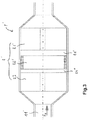
- an exhaust gas treatment device 1 comprises a casing 10 of cylindrical shape and extending along a principal axis A, an inlet 11 at a first end of the casing 10 and an outlet 12 at the end opposite to that of the inlet 11.
- the connections between the inlet 11, the outlet 12 and the casing 10 are of frustoconical shape.
- the device 1 further comprises a substrate 2 in two parts separated by an interval 24.
- the first portion 21 is subdivided into four equal sectors 210, seen in section perpendicular to the longitudinal axis.
- the sectors 210 are made of ceramic and comprise channels 2101 in which the exhaust gases are intended to pass.
- the interior of the channels 2101 is coated with a catalytic substance, not shown, conventionally used for this application.
- a space 212 is formed in the form of a cross and is occupied by a metal housing 213 filled with a phase change material.
- the phase change material is chosen to have a melting temperature higher than the initiation temperature of the catalytic substance. At ambient temperature, the phase change material is thus in solid form.
- a first ply 214 is interposed between the sectors 210 and the housing 213.
- a second insulating refractory ply 211 is interposed between the sectors 210 and the envelope 10.
- the plies 211, 214 are made for example of ceramic fibers.
- the second portion 22 of the substrate 2 is formed of a single block 220 of ceramic pierced with channels 2201 and kept centered in the casing 10 by a third insulating sheet 221 refractory.
- the channels 2201 that it comprises are also coated with a catalytic substance.
- the device 1 is traversed by the exhaust gases in the direction indicated by the arrow F1, entering through the inlet 11.
- the gases pass through the channels 2201 of the second portion 22 of the substrate, the interval 24 and the channels 2101 of the first part 21 and exit through the outlet 12.
- the device 1 is generally at room temperature and the phase-change material is solidified in the housing 213.
- the gases passing through the device 1 are hot and gradually heat up the second part 22 of the substrate 2 first. This has reached the initiation temperature, an exothermic reaction is initiated and increases the temperature of the downstream gas flow.
- the flow of gas arrives at the first portion 21, which then accumulates heat by melting the phase change material.
- the second part 22, without phase change material cools down and reaches, for example, a temperature below the ignition temperature. Meanwhile, the first portion 21 is maintained at a temperature above the priming temperature until the entire phase change material has solidified. Under these conditions, a new start of the engine, the treatment of the exhaust gas on the first portion 21 of the substrate 2 is immediate. This limits the periods during which the processing device 1 does not work.
- the processing device 1 'further comprises a third substrate portion 23, identical to the first portion 21' and placed on the input side 11 '.
- the third part 23 with a phase change material there is the third part 23 with a phase change material, the second part 22 'without phase change material and the first part 21' with phase change material, with intervals 24 ', 24 "between each part.
Landscapes
- Chemical & Material Sciences (AREA)
- Engineering & Computer Science (AREA)
- Chemical Kinetics & Catalysis (AREA)
- Combustion & Propulsion (AREA)
- Mechanical Engineering (AREA)
- General Engineering & Computer Science (AREA)
- Health & Medical Sciences (AREA)
- Toxicology (AREA)
- Exhaust Gas After Treatment (AREA)
- Physical Or Chemical Processes And Apparatus (AREA)
Claims (10)
- Vorrichtung zur Behandlung der Abgase eines Fahrzeugs, welche einen Einlass (11) für das Gas und einen Auslass (12), ein Substrat (2), das sich in einer Längsrichtung erstreckt und zwischen dem Einlass (11) und dem Auslass (12) angeordnet ist, wobei das Substrat (2) katalytische Eigenschaften aufweist, und ein Phasenwechselmaterial, das in der Nähe des Substrats (2) angeordnet ist, umfasst, dadurch gekennzeichnet, dass das Substrat (2) entlang wenigstens eines ersten Teils (21) in wenigstens drei Sektoren (210) aufgeteilt angeordnet ist, die sich in der Längsrichtung erstrecken und voneinander beabstandet sind, um einen Raum (212) zu bilden, in welchem ein einziges Gehäuse (213) ausreichend ist, um das Phasenwechselmaterial einzuschließen, das den Raum (212) zwischen den Sektoren (210) einnimmt.
- Vorrichtung nach Anspruch 1, dadurch gekennzeichnet, dass das Gehäuse, welches das Phasenwechselmaterial enthält, metallisch ist.
- Vorrichtung nach Anspruch 2, wobei das metallische Gehäuse (213) einen konstanten Querschnitt in Form eines Sterns mit so vielen Strahlen, wie Sektoren vorhanden sind, aufweist.
- Vorrichtung nach Anspruch 2 oder 3, wobei eine erste Matte (214) zwischen dem Gehäuse (213) und den Sektoren (210) angeordnet ist.
- Vorrichtung nach Anspruch 1, dadurch gekennzeichnet, dass sie eine metallische Hülle (10) aufweist, die ein Leitungsrohr für die Abgase bildet und das Substrat (2) enthält.
- Vorrichtung nach Anspruch 5, wobei eine zweite Matte (211) zwischen der Hülle (10) und dem Substrat (2) angeordnet ist.
- Vorrichtung nach einem der Ansprüche 1 bis 6, dadurch gekennzeichnet, dass sie außerdem wenigstens einen zweiten Teil (22) mit einem nicht aufgeteilten Querschnitt aufweist, der stromaufwärts oder stromabwärts des ersten Teils (21) angeordnet ist.
- Vorrichtung nach Anspruch 7, wobei ein Zwischenraum (24) zwischen dem ersten und dem zweiten Teil (21, 22) des Substrats ausgebildet ist.
- Vorrichtung nach einem der Ansprüche 1 bis 7, wobei das Substrat (2) aus Keramik besteht.
- Vorrichtung nach einem der Ansprüche 1 bis 9, wobei das Substrat (2) von Längskanälen (2101, 2201) für das Durchströmen der Gase durchbohrt ist.
Applications Claiming Priority (2)
| Application Number | Priority Date | Filing Date | Title |
|---|---|---|---|
| FR1351504A FR3002278B1 (fr) | 2013-02-21 | 2013-02-21 | Dispositif de traitement des gaz d'echappement par catalyse. |
| PCT/FR2014/050232 WO2014147305A1 (fr) | 2013-02-21 | 2014-02-07 | Dispositif de traitement des gaz d'echappement par catalyse |
Publications (2)
| Publication Number | Publication Date |
|---|---|
| EP2959124A1 EP2959124A1 (de) | 2015-12-30 |
| EP2959124B1 true EP2959124B1 (de) | 2019-07-17 |
Family
ID=48692600
Family Applications (1)
| Application Number | Title | Priority Date | Filing Date |
|---|---|---|---|
| EP14706905.8A Active EP2959124B1 (de) | 2013-02-21 | 2014-02-07 | Vorrichtung zur behandlung von abgasen durch katalyse |
Country Status (3)
| Country | Link |
|---|---|
| EP (1) | EP2959124B1 (de) |
| FR (1) | FR3002278B1 (de) |
| WO (1) | WO2014147305A1 (de) |
Families Citing this family (1)
| Publication number | Priority date | Publication date | Assignee | Title |
|---|---|---|---|---|
| CN107166533A (zh) * | 2017-06-13 | 2017-09-15 | 庞继巧 | 一种手术烟雾处理装置 |
Family Cites Families (4)
| Publication number | Priority date | Publication date | Assignee | Title |
|---|---|---|---|---|
| DE10004545A1 (de) * | 2000-02-02 | 2001-10-31 | Emitec Emissionstechnologie | Verbund aus Wabenkörper und Wärmespeicher und Verfahren zu dessen Betrieb |
| DE10048518B4 (de) * | 2000-09-29 | 2006-03-09 | Dr.Ing.H.C. F. Porsche Ag | Katalysatorvorrichtung |
| DE102004052106B4 (de) * | 2004-10-26 | 2008-01-10 | J. Eberspächer GmbH & Co. KG | Kombination eines Katalysators mit einem Wärmespeicher |
| DE102009034655A1 (de) | 2009-07-24 | 2011-01-27 | J. Eberspächer GmbH & Co. KG | Latentwärmespeicher |
-
2013
- 2013-02-21 FR FR1351504A patent/FR3002278B1/fr not_active Expired - Fee Related
-
2014
- 2014-02-07 EP EP14706905.8A patent/EP2959124B1/de active Active
- 2014-02-07 WO PCT/FR2014/050232 patent/WO2014147305A1/fr not_active Ceased
Non-Patent Citations (1)
| Title |
|---|
| None * |
Also Published As
| Publication number | Publication date |
|---|---|
| EP2959124A1 (de) | 2015-12-30 |
| FR3002278B1 (fr) | 2016-07-01 |
| WO2014147305A1 (fr) | 2014-09-25 |
| FR3002278A1 (fr) | 2014-08-22 |
Similar Documents
| Publication | Publication Date | Title |
|---|---|---|
| BE898076A (fr) | Regeneration des filtres catalytiques a particules et appareil pour sa mise en oeuvre. | |
| EP1373690B1 (de) | Partikelfilter zum reinigen der abgase von verbrennungsmotoren | |
| EP0519778B1 (de) | Motorauspufflinie zum schnellen Erregen eines Katalysators | |
| EP2053311B1 (de) | Wände einer Brennkammer mit optimierter Verdünnung und Abkühlung, damit ausgerüstete Brennkammer und Turbomaschine | |
| FR3002278A1 (fr) | Dispositif de traitement des gaz d'echappement par catalyse. | |
| EP2076659A1 (de) | Mit einem kraftstoffeinspritzventil und mitteln zur homogenisierung von verbrannten gasen versehene abgasleitung | |
| EP1915519B1 (de) | Auspuffrohr | |
| WO2008142350A1 (fr) | Conduit d'échappement de véhicule automobile | |
| EP3204147B1 (de) | Vorrichtung zur katalytischen umwandlung mit reduzierter aktivierungszeit | |
| FR3066408B1 (fr) | Dispositif de post-traitement des gaz d’echappement d’un moteur thermique | |
| EP1672194A1 (de) | Verfahren zur Regeneration eines Partikelfilters mit einer katalytischen Verbrennungseinheit und das Verfahren verwendende Filtervorrichtung | |
| EP3098410B1 (de) | Kompaktes abgasreinugungssystem eines fahrzeugs | |
| FR2879236A1 (fr) | Filtre a particules a section de canaux variable | |
| FR3079264A1 (fr) | Organe de purification de gaz d'echappement chauffant et dispositif de purification comprenant un tel organe de purification | |
| EP3415732B1 (de) | Katalytisches abgasnachbehandlungssystem mit wärmespeichermittel für ein hybridfahrzeug | |
| FR2858022A1 (fr) | Dispositif d'admission d'air pour moteur diesel catalyse | |
| FR2870566A1 (fr) | Dispositif et procede de traitement des gaz d'echappement d'un moteur a combustion interne suralimente en vue de leur depollution | |
| CA2671884A1 (fr) | Media filtrant pour dispositif de filtration des gaz d'echappement d'un moteur diesel, dispositif de filtration mettant en oeuvre un tel media, et ligne d'echappement des gaz d'unmoteur a combustion interne mettant en oeuvre un tel dispositif | |
| FR3018310A1 (fr) | Catalyseur trois voies | |
| FR2941490A1 (fr) | Ligne d'echappement de moteur a combustion interne equipee d'un systeme d'isolation thermique du filtre a particules | |
| EP2078145A1 (de) | System zur wärmeisolierung eines motors | |
| FR2946085A1 (fr) | Filre a particules comprenant un dispositif de protection de son enveloppe. | |
| WO2006087454A1 (fr) | Dispositif de depollution des gaz d'echappement d'un moteur thermique | |
| FR2862341A1 (fr) | Moteur a combustion interne avec un dispositif d'epuration de gaz d'echappement, et procede d'exploitation d'un moteur a combustion interne | |
| FR2823252A1 (fr) | Corps filtrant pour la filtration de particules contenues dans les gaz d'echappement d'un moteur a combustion interne |
Legal Events
| Date | Code | Title | Description |
|---|---|---|---|
| PUAI | Public reference made under article 153(3) epc to a published international application that has entered the european phase |
Free format text: ORIGINAL CODE: 0009012 |
|
| 17P | Request for examination filed |
Effective date: 20150707 |
|
| AK | Designated contracting states |
Kind code of ref document: A1 Designated state(s): AL AT BE BG CH CY CZ DE DK EE ES FI FR GB GR HR HU IE IS IT LI LT LU LV MC MK MT NL NO PL PT RO RS SE SI SK SM TR |
|
| AX | Request for extension of the european patent |
Extension state: BA ME |
|
| DAX | Request for extension of the european patent (deleted) | ||
| STAA | Information on the status of an ep patent application or granted ep patent |
Free format text: STATUS: EXAMINATION IS IN PROGRESS |
|
| 17Q | First examination report despatched |
Effective date: 20170210 |
|
| RIC1 | Information provided on ipc code assigned before grant |
Ipc: F01N 5/02 20060101ALI20181121BHEP Ipc: F01N 3/28 20060101ALI20181121BHEP Ipc: F01N 3/20 20060101AFI20181121BHEP |
|
| GRAP | Despatch of communication of intention to grant a patent |
Free format text: ORIGINAL CODE: EPIDOSNIGR1 |
|
| STAA | Information on the status of an ep patent application or granted ep patent |
Free format text: STATUS: GRANT OF PATENT IS INTENDED |
|
| INTG | Intention to grant announced |
Effective date: 20190222 |
|
| GRAS | Grant fee paid |
Free format text: ORIGINAL CODE: EPIDOSNIGR3 |
|
| GRAA | (expected) grant |
Free format text: ORIGINAL CODE: 0009210 |
|
| STAA | Information on the status of an ep patent application or granted ep patent |
Free format text: STATUS: THE PATENT HAS BEEN GRANTED |
|
| AK | Designated contracting states |
Kind code of ref document: B1 Designated state(s): AL AT BE BG CH CY CZ DE DK EE ES FI FR GB GR HR HU IE IS IT LI LT LU LV MC MK MT NL NO PL PT RO RS SE SI SK SM TR |
|
| REG | Reference to a national code |
Ref country code: GB Ref legal event code: FG4D Free format text: NOT ENGLISH |
|
| REG | Reference to a national code |
Ref country code: CH Ref legal event code: EP |
|
| REG | Reference to a national code |
Ref country code: DE Ref legal event code: R096 Ref document number: 602014050092 Country of ref document: DE |
|
| REG | Reference to a national code |
Ref country code: IE Ref legal event code: FG4D Free format text: LANGUAGE OF EP DOCUMENT: FRENCH |
|
| REG | Reference to a national code |
Ref country code: AT Ref legal event code: REF Ref document number: 1156024 Country of ref document: AT Kind code of ref document: T Effective date: 20190815 |
|
| REG | Reference to a national code |
Ref country code: NL Ref legal event code: MP Effective date: 20190717 |
|
| REG | Reference to a national code |
Ref country code: LT Ref legal event code: MG4D |
|
| REG | Reference to a national code |
Ref country code: AT Ref legal event code: MK05 Ref document number: 1156024 Country of ref document: AT Kind code of ref document: T Effective date: 20190717 |
|
| PG25 | Lapsed in a contracting state [announced via postgrant information from national office to epo] |
Ref country code: BG Free format text: LAPSE BECAUSE OF FAILURE TO SUBMIT A TRANSLATION OF THE DESCRIPTION OR TO PAY THE FEE WITHIN THE PRESCRIBED TIME-LIMIT Effective date: 20191017 Ref country code: AT Free format text: LAPSE BECAUSE OF FAILURE TO SUBMIT A TRANSLATION OF THE DESCRIPTION OR TO PAY THE FEE WITHIN THE PRESCRIBED TIME-LIMIT Effective date: 20190717 Ref country code: NO Free format text: LAPSE BECAUSE OF FAILURE TO SUBMIT A TRANSLATION OF THE DESCRIPTION OR TO PAY THE FEE WITHIN THE PRESCRIBED TIME-LIMIT Effective date: 20191017 Ref country code: NL Free format text: LAPSE BECAUSE OF FAILURE TO SUBMIT A TRANSLATION OF THE DESCRIPTION OR TO PAY THE FEE WITHIN THE PRESCRIBED TIME-LIMIT Effective date: 20190717 Ref country code: PT Free format text: LAPSE BECAUSE OF FAILURE TO SUBMIT A TRANSLATION OF THE DESCRIPTION OR TO PAY THE FEE WITHIN THE PRESCRIBED TIME-LIMIT Effective date: 20191118 Ref country code: FI Free format text: LAPSE BECAUSE OF FAILURE TO SUBMIT A TRANSLATION OF THE DESCRIPTION OR TO PAY THE FEE WITHIN THE PRESCRIBED TIME-LIMIT Effective date: 20190717 Ref country code: LT Free format text: LAPSE BECAUSE OF FAILURE TO SUBMIT A TRANSLATION OF THE DESCRIPTION OR TO PAY THE FEE WITHIN THE PRESCRIBED TIME-LIMIT Effective date: 20190717 Ref country code: SE Free format text: LAPSE BECAUSE OF FAILURE TO SUBMIT A TRANSLATION OF THE DESCRIPTION OR TO PAY THE FEE WITHIN THE PRESCRIBED TIME-LIMIT Effective date: 20190717 Ref country code: HR Free format text: LAPSE BECAUSE OF FAILURE TO SUBMIT A TRANSLATION OF THE DESCRIPTION OR TO PAY THE FEE WITHIN THE PRESCRIBED TIME-LIMIT Effective date: 20190717 |
|
| PG25 | Lapsed in a contracting state [announced via postgrant information from national office to epo] |
Ref country code: AL Free format text: LAPSE BECAUSE OF FAILURE TO SUBMIT A TRANSLATION OF THE DESCRIPTION OR TO PAY THE FEE WITHIN THE PRESCRIBED TIME-LIMIT Effective date: 20190717 Ref country code: GR Free format text: LAPSE BECAUSE OF FAILURE TO SUBMIT A TRANSLATION OF THE DESCRIPTION OR TO PAY THE FEE WITHIN THE PRESCRIBED TIME-LIMIT Effective date: 20191018 Ref country code: IS Free format text: LAPSE BECAUSE OF FAILURE TO SUBMIT A TRANSLATION OF THE DESCRIPTION OR TO PAY THE FEE WITHIN THE PRESCRIBED TIME-LIMIT Effective date: 20191117 Ref country code: RS Free format text: LAPSE BECAUSE OF FAILURE TO SUBMIT A TRANSLATION OF THE DESCRIPTION OR TO PAY THE FEE WITHIN THE PRESCRIBED TIME-LIMIT Effective date: 20190717 Ref country code: LV Free format text: LAPSE BECAUSE OF FAILURE TO SUBMIT A TRANSLATION OF THE DESCRIPTION OR TO PAY THE FEE WITHIN THE PRESCRIBED TIME-LIMIT Effective date: 20190717 Ref country code: ES Free format text: LAPSE BECAUSE OF FAILURE TO SUBMIT A TRANSLATION OF THE DESCRIPTION OR TO PAY THE FEE WITHIN THE PRESCRIBED TIME-LIMIT Effective date: 20190717 |
|
| PG25 | Lapsed in a contracting state [announced via postgrant information from national office to epo] |
Ref country code: TR Free format text: LAPSE BECAUSE OF FAILURE TO SUBMIT A TRANSLATION OF THE DESCRIPTION OR TO PAY THE FEE WITHIN THE PRESCRIBED TIME-LIMIT Effective date: 20190717 |
|
| PG25 | Lapsed in a contracting state [announced via postgrant information from national office to epo] |
Ref country code: IT Free format text: LAPSE BECAUSE OF FAILURE TO SUBMIT A TRANSLATION OF THE DESCRIPTION OR TO PAY THE FEE WITHIN THE PRESCRIBED TIME-LIMIT Effective date: 20190717 Ref country code: PL Free format text: LAPSE BECAUSE OF FAILURE TO SUBMIT A TRANSLATION OF THE DESCRIPTION OR TO PAY THE FEE WITHIN THE PRESCRIBED TIME-LIMIT Effective date: 20190717 Ref country code: DK Free format text: LAPSE BECAUSE OF FAILURE TO SUBMIT A TRANSLATION OF THE DESCRIPTION OR TO PAY THE FEE WITHIN THE PRESCRIBED TIME-LIMIT Effective date: 20190717 Ref country code: EE Free format text: LAPSE BECAUSE OF FAILURE TO SUBMIT A TRANSLATION OF THE DESCRIPTION OR TO PAY THE FEE WITHIN THE PRESCRIBED TIME-LIMIT Effective date: 20190717 Ref country code: RO Free format text: LAPSE BECAUSE OF FAILURE TO SUBMIT A TRANSLATION OF THE DESCRIPTION OR TO PAY THE FEE WITHIN THE PRESCRIBED TIME-LIMIT Effective date: 20190717 |
|
| PG25 | Lapsed in a contracting state [announced via postgrant information from national office to epo] |
Ref country code: CZ Free format text: LAPSE BECAUSE OF FAILURE TO SUBMIT A TRANSLATION OF THE DESCRIPTION OR TO PAY THE FEE WITHIN THE PRESCRIBED TIME-LIMIT Effective date: 20190717 Ref country code: SM Free format text: LAPSE BECAUSE OF FAILURE TO SUBMIT A TRANSLATION OF THE DESCRIPTION OR TO PAY THE FEE WITHIN THE PRESCRIBED TIME-LIMIT Effective date: 20190717 Ref country code: IS Free format text: LAPSE BECAUSE OF FAILURE TO SUBMIT A TRANSLATION OF THE DESCRIPTION OR TO PAY THE FEE WITHIN THE PRESCRIBED TIME-LIMIT Effective date: 20200224 Ref country code: SK Free format text: LAPSE BECAUSE OF FAILURE TO SUBMIT A TRANSLATION OF THE DESCRIPTION OR TO PAY THE FEE WITHIN THE PRESCRIBED TIME-LIMIT Effective date: 20190717 |
|
| REG | Reference to a national code |
Ref country code: DE Ref legal event code: R097 Ref document number: 602014050092 Country of ref document: DE |
|
| PLBE | No opposition filed within time limit |
Free format text: ORIGINAL CODE: 0009261 |
|
| STAA | Information on the status of an ep patent application or granted ep patent |
Free format text: STATUS: NO OPPOSITION FILED WITHIN TIME LIMIT |
|
| PG2D | Information on lapse in contracting state deleted |
Ref country code: IS |
|
| 26N | No opposition filed |
Effective date: 20200603 |
|
| PG25 | Lapsed in a contracting state [announced via postgrant information from national office to epo] |
Ref country code: SI Free format text: LAPSE BECAUSE OF FAILURE TO SUBMIT A TRANSLATION OF THE DESCRIPTION OR TO PAY THE FEE WITHIN THE PRESCRIBED TIME-LIMIT Effective date: 20190717 |
|
| REG | Reference to a national code |
Ref country code: CH Ref legal event code: PL |
|
| REG | Reference to a national code |
Ref country code: BE Ref legal event code: MM Effective date: 20200229 |
|
| PG25 | Lapsed in a contracting state [announced via postgrant information from national office to epo] |
Ref country code: LU Free format text: LAPSE BECAUSE OF NON-PAYMENT OF DUE FEES Effective date: 20200207 Ref country code: MC Free format text: LAPSE BECAUSE OF FAILURE TO SUBMIT A TRANSLATION OF THE DESCRIPTION OR TO PAY THE FEE WITHIN THE PRESCRIBED TIME-LIMIT Effective date: 20190717 |
|
| PG25 | Lapsed in a contracting state [announced via postgrant information from national office to epo] |
Ref country code: CH Free format text: LAPSE BECAUSE OF NON-PAYMENT OF DUE FEES Effective date: 20200229 Ref country code: LI Free format text: LAPSE BECAUSE OF NON-PAYMENT OF DUE FEES Effective date: 20200229 |
|
| PG25 | Lapsed in a contracting state [announced via postgrant information from national office to epo] |
Ref country code: IE Free format text: LAPSE BECAUSE OF NON-PAYMENT OF DUE FEES Effective date: 20200207 |
|
| PG25 | Lapsed in a contracting state [announced via postgrant information from national office to epo] |
Ref country code: BE Free format text: LAPSE BECAUSE OF NON-PAYMENT OF DUE FEES Effective date: 20200229 |
|
| PG25 | Lapsed in a contracting state [announced via postgrant information from national office to epo] |
Ref country code: MT Free format text: LAPSE BECAUSE OF FAILURE TO SUBMIT A TRANSLATION OF THE DESCRIPTION OR TO PAY THE FEE WITHIN THE PRESCRIBED TIME-LIMIT Effective date: 20190717 Ref country code: CY Free format text: LAPSE BECAUSE OF FAILURE TO SUBMIT A TRANSLATION OF THE DESCRIPTION OR TO PAY THE FEE WITHIN THE PRESCRIBED TIME-LIMIT Effective date: 20190717 |
|
| PG25 | Lapsed in a contracting state [announced via postgrant information from national office to epo] |
Ref country code: MK Free format text: LAPSE BECAUSE OF FAILURE TO SUBMIT A TRANSLATION OF THE DESCRIPTION OR TO PAY THE FEE WITHIN THE PRESCRIBED TIME-LIMIT Effective date: 20190717 |
|
| P01 | Opt-out of the competence of the unified patent court (upc) registered |
Effective date: 20230608 |
|
| REG | Reference to a national code |
Ref country code: GB Ref legal event code: 732E Free format text: REGISTERED BETWEEN 20231228 AND 20240103 |
|
| REG | Reference to a national code |
Ref country code: DE Ref legal event code: R081 Ref document number: 602014050092 Country of ref document: DE Owner name: NEW H POWERTRAIN HOLDING, S.L.U., ES Free format text: FORMER OWNER: RENAULT S.A.S., BOULOGNE-BILLANCOURT, FR |
|
| PGFP | Annual fee paid to national office [announced via postgrant information from national office to epo] |
Ref country code: GB Payment date: 20260219 Year of fee payment: 13 |
|
| PGFP | Annual fee paid to national office [announced via postgrant information from national office to epo] |
Ref country code: DE Payment date: 20260218 Year of fee payment: 13 |
|
| PGFP | Annual fee paid to national office [announced via postgrant information from national office to epo] |
Ref country code: FR Payment date: 20260218 Year of fee payment: 13 |