EP2958412A1 - Method for controlling temperature of inverter system by controlling a fan - Google Patents
Method for controlling temperature of inverter system by controlling a fan Download PDFInfo
- Publication number
- EP2958412A1 EP2958412A1 EP15171432.6A EP15171432A EP2958412A1 EP 2958412 A1 EP2958412 A1 EP 2958412A1 EP 15171432 A EP15171432 A EP 15171432A EP 2958412 A1 EP2958412 A1 EP 2958412A1
- Authority
- EP
- European Patent Office
- Prior art keywords
- fan
- temperature
- control signal
- predetermined
- inverter
- Prior art date
- Legal status (The legal status is an assumption and is not a legal conclusion. Google has not performed a legal analysis and makes no representation as to the accuracy of the status listed.)
- Granted
Links
Images




Classifications
-
- G—PHYSICS
- G05—CONTROLLING; REGULATING
- G05D—SYSTEMS FOR CONTROLLING OR REGULATING NON-ELECTRIC VARIABLES
- G05D23/00—Control of temperature
- G05D23/19—Control of temperature characterised by the use of electric means
-
- H—ELECTRICITY
- H05—ELECTRIC TECHNIQUES NOT OTHERWISE PROVIDED FOR
- H05K—PRINTED CIRCUITS; CASINGS OR CONSTRUCTIONAL DETAILS OF ELECTRIC APPARATUS; MANUFACTURE OF ASSEMBLAGES OF ELECTRICAL COMPONENTS
- H05K7/00—Constructional details common to different types of electric apparatus
- H05K7/20—Modifications to facilitate cooling, ventilating, or heating
- H05K7/20009—Modifications to facilitate cooling, ventilating, or heating using a gaseous coolant in electronic enclosures
- H05K7/20209—Thermal management, e.g. fan control
-
- G—PHYSICS
- G05—CONTROLLING; REGULATING
- G05B—CONTROL OR REGULATING SYSTEMS IN GENERAL; FUNCTIONAL ELEMENTS OF SUCH SYSTEMS; MONITORING OR TESTING ARRANGEMENTS FOR SUCH SYSTEMS OR ELEMENTS
- G05B15/00—Systems controlled by a computer
- G05B15/02—Systems controlled by a computer electric
-
- H—ELECTRICITY
- H05—ELECTRIC TECHNIQUES NOT OTHERWISE PROVIDED FOR
- H05K—PRINTED CIRCUITS; CASINGS OR CONSTRUCTIONAL DETAILS OF ELECTRIC APPARATUS; MANUFACTURE OF ASSEMBLAGES OF ELECTRICAL COMPONENTS
- H05K7/00—Constructional details common to different types of electric apparatus
- H05K7/20—Modifications to facilitate cooling, ventilating, or heating
- H05K7/2089—Modifications to facilitate cooling, ventilating, or heating for power electronics, e.g. for inverters for controlling motor
- H05K7/20909—Forced ventilation, e.g. on heat dissipaters coupled to components
-
- H—ELECTRICITY
- H05—ELECTRIC TECHNIQUES NOT OTHERWISE PROVIDED FOR
- H05K—PRINTED CIRCUITS; CASINGS OR CONSTRUCTIONAL DETAILS OF ELECTRIC APPARATUS; MANUFACTURE OF ASSEMBLAGES OF ELECTRICAL COMPONENTS
- H05K7/00—Constructional details common to different types of electric apparatus
- H05K7/20—Modifications to facilitate cooling, ventilating, or heating
- H05K7/2089—Modifications to facilitate cooling, ventilating, or heating for power electronics, e.g. for inverters for controlling motor
- H05K7/20945—Thermal management, e.g. inverter temperature control
Definitions
- the present disclosure relates to a temperature control method of an inverter system by controlling a fan. More specifically, the present disclosure relates to a temperature control method of an inverter system by controlling a fan to suppress temperature increase in a SMPS (Switched-Mode Power Supply) and peripherals by controlling a fan when the inverter is stopped after inputting electrical power to the inverter.
- SMPS Switchched-Mode Power Supply
- An inverter is a device to control torque and speed of a motor. There have been introduced various motor speed controlling methods, some of which representative methods are the first voltage control method and the frequency control method.
- the inverter may be used for, such as efficiency control, power factor control, etc.
- the inverter may also be used by being applied to, such as a preliminary power supply, an uninterruptible power supply for a computer, direct current transmission, etc.
- an inverter may control speed of the blower according to types or quantity of products. Temperature inside the heating furnace may be controlled as the optimal temperature by controlling air volume of the blower, and the quality of the product can be improved as well. Thereby, a great retrenchment in energy consumption can be obtained.
- Currently, researches for technology to efficiently control an inverter when an urgent situation such as instantaneous blackout occurs are conducted actively.
- An inverter includes an SMPS (Switched-Mode Power Supply) inside thereof.
- the SMPS is a power supply including a switching regulator to efficiently convert electric power.
- the SMPS becomes a heat source to increase temperature of internal components of the inverter, when the inverter is not driven while being inputted with electric power.
- Temperature of the SMPS increases as DC (Direct Current)-link voltage and switching frequency grows larger. Load of the SMPS increases and internal convection of the inverter occurs to suppress temperature increase in peripherals due to the SMPS, when the invert and the fan start to be driven.
- DC Direct Current
- a heat sink at a lower part of the invert can prevent a three-leg switch at an output part of the inverter from an excessive temperature increase.
- the heat sink may not suppress temperature increase of the SMPS. Temperature of the SMPS and the peripherals comes to increase due to load reduction of the SMPS and deterioration in internal convection of the inverter, when the inverter and the fan are stopped.
- the temperature increase of SMPS may be lessened by inserting a dumnry load, when using a method to change a switching frequency according to the load of SMPS.
- the method is suitable for a product in which internal space is confined because additional components are required. Furthermore, effect of such method is not significant.
- the temperature increase of peripherals may be suppressed by constantly driving the fan when the inverter is stopped.
- a certain amount of electric power should be constantly consumed.
- a technical challenge that the present disclosure intends to achieve is, to provide a temperature control method of an inverter system by using a fan control to suppress temperature increase in a SMPS and peripherals by improving the environment for convection in the inverter through the fan control.
- a method for controlling temperature of an inverter system having an inverter and a cooling fan comprising: obtaining an internal temperature of the inverter and a DC (Direct Current)-link voltage of the inverter; and outputting a fan driving control signal for driving the fan or maintaining the fan being driven to the fan, when the internal temperature is above a predetermined fan drive setting temperature and the DC-link voltage is above a predetermined fan drive setting voltage.
- DC Direct Current
- the step of outputting the fan driving control signal to the fan may include: outputting a fan driving control signal for driving the fan to the fan, when the internal temperature is above a predetermined fan drive setting temperature and the DC-link voltage is above a predetermined fan drive setting voltage, in a state where the fan is stopped.
- the step of outputting the fan driving control signal to the fan may include: outputting a fan driving control signal for maintaining the fan being driven to the fan, when the internal temperature is above a predetermined fan drive setting temperature and the DC-link voltage is above a predetermined fan drive setting voltage, in a state where the fan is being driven.
- the step of outputting the fan driving control signal to the fan may include: determining whether the internal temperature is above the predetermined fan driving setting temperature; determining whether the DC-link voltage is above the predetermined fan driving setting voltage, when the internal temperature is determined to be above the predetermined fan driving setting temperature; and outputting the fan driving control signal for driving the fan or maintaining the fan being driven to the fan, when the DC-link voltage is determined to be above a predetermined fan drive setting voltage.
- the step of outputting the fan driving control signal to the fan may include: outputting the fan driving control signal for driving the fan to the fan when the fan is stopped, when the DC-link voltage is determined to be above the predetermined fan drive setting voltage.
- the step of outputting the fan driving control signal to the fan may include: outputting the fan driving control signal for maintaining the fan being driven to the fan when the fan is being driven, when the DC-link voltage is determined to be above the predetermined fan drive setting voltage.
- the step of outputting the fan driving control signal to the fan may include: determining whether the DC-link voltage is above the predetermined fan driving setting voltage; determining whether the internal temperature is above the predetermined fan driving setting temperature, when the DC-link voltage is determined to be above the predetermined fan driving setting voltage; and outputting the fan driving control signal for driving the fan or maintaining the fan being driven to the fan, when the internal temperature is determined to be above the predetermined fan drive setting temperature.
- the step of outputting the fan driving control signal to the fan may include: outputting a fan driving control signal for driving the fan to the fan when the fan is stopped, when the internal temperature is determined to be above a predetermined fan drive setting temperature.
- the step of outputting the fan driving control signal to the fan may include: outputting a fan driving control signal for maintain the fan being driven to the fan, when the internal temperature is determined to be above the predetermined fan drive setting temperature, in the state where the fan is being driven.
- the method for controlling temperature of an inverter system by using a fan control may further include: outputting a fan stopping control signal for stopping the fan to the fan in response to the fan driving control signal, when the internal temperature is determined to be under a predetermined fan stop setting temperature or the DC-link voltage is determined to be under a predetermined fan stop setting voltage, in the state where the fan is being driven.
- the fan stop setting temperature may be predetermined to be under the fan drive setting temperature
- the fan stop setting voltage may be predetermined to be under the fan drive setting temperature
- temperature increase of the SMPS and the peripherals may be suppressed by improving the environment for convection in the inverter through the fan control.
- Driving the fan by using an internal temperature and a DC-link voltage as control factors can suppress the temperature increase of peripherals more efficiently than constantly driving the fan.
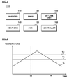
- FIG. 1 is a block diagram of an inverter system according to an exemplary embodiment of the present disclosure.
- an inverter system (100) may include an inverter (110), a SMPS (120), a DC-link unit (130), a heat sink (140), a fan (150), and a controller (160).
- the SMPS Switchched-Mode Power Supply (120) supplies electric power to the inverter (110), and may include a switching regulator to efficiently convert the supplied electric power.
- the SMPS may become a heat source to increase temperature of internal components of the inverter, when the inverter (110) is not driven while being inputted with electric power. Temperature of the SMPS(120) increases as DC (Direct Current)-link voltage and switching frequency grows larger.
- An SMPS of which switching frequency is variable according to load may be used as the SMPS (120).
- An additional effect of suppressing temperature increase may be expected when using the SMPS of variable switching frequency according to load, since load of the SMPS (120) increases when the fan (150) is driven.
- the electric power to drive the fan may become the load of the SMPS (120) to reduce switching frequency and to suppress temperature increase of the SMPS (120).
- the DC-link unit (130) converts alternate current electric power rectified by being supplied to the inverter (110) to direct current electric power.
- the DC-link unit (130) may include a condenser for smoothing the rectified electric power.
- the heat sink (140) prevents temperature increase of the inverter (110) or the SMPS (120), by being installed at a lower part of the inverter (110) or the SMPS (120), or by being installed adjacent to the inverter (110) or the SMPS (120).
- the fan (150) is installed in order to prevent temperature increase generated by the inverter (110) and the SMPS (120) and to generate a convection flow for cooling.
- the fan (150) is driven by a fan driving control signal of the controller (160), and stopped by a fan stopping control signal.
- the controller (160) outputs a fan driving control signal for driving the fan (150) or maintaining the driven fan (150) being driven to the fan (150) after applying an electric power to the inverter (110), or outputs a fan stopping control signal for stopping the fan (150) being driven or maintaining the stopped fan (150) being still stopped.
- the controller (160) may use an internal temperature of the inverter (110) and a DC-link voltage of the DC-link unit (130) as control factors to determine whether the fan (150) is to be driven.
- the controller (160) includes a predetermined fan drive setting temperature to drive the stopped fan (150) by being compared to the internal temperature of the inverter (110).
- the controller (160) may determine that a first condition to drive the fan (150) is satisfied, when the internal temperature of the inverter (110) measured inside the inverter (110) is above the fan driving setting temperature.
- the controller (160) includes a predetermined fan drive setting voltage to drive the stopped fan (150) by being compared to the DC-link voltage of the inverter (110).
- the controller (160) may determine that a first condition to drive the fan (150) is satisfied, when the measured DC-link voltage of the inverter (110) is above the fan driving setting voltage.
- the controller (160) may output a fan driving control signal for driving the fan (150) the fan (150), when both of the fist and the second conditions are satisfied, that is, when the internal temperature and the DC-link voltage are above the predetermined fan drive setting temperature and the predetermined fan drive setting voltage, respectively.
- Convection may occur in the inverter (110) to suppress temperature increase of the SMPS (120) and the peripherals, when the fan (150) is driven by the fan driving control signal outputted from the controller (160).
- the controller (160) includes a fan stop setting temperature and a fan stop setting voltage as well as the fan drive setting temperature and the fan drive setting voltage, in order to determine whether the fan (150) is to be driven or stopped.
- the controller (160) outputs a fan stopping control signal for stopping the fan (150) to the fan (150), when the internal temperature is determined to be under the predetermined fan stop setting temperature or the DC-link voltage is determined to be under the predetermined fan stop setting voltage.
- the fan stop setting temperature may be predetermined to be under the fan drive setting temperature to prevent drive/stop operation of the fan (150) be frequently repeated.
- the fan (150) is driven when the internal temperature is above the predetermined fan drive setting temperature and the DC-link voltage is above the predetermined fan drive setting voltage.
- the temperature increase of the peripherals may be effectively suppressed due to the improved internal convection environment of the inverter (110) through the drive of the fan (150).
- FIG. 2 is a view illustrating a fan drive setting temperature and a fan stop setting temperature in an inverter system according to an exemplary embodiment of the present disclosure.
- the fan stop setting temperature (Ts) is predetermined to be under the fan drive setting temperature (Td).
- the controller (160) outputs a fan driving control signal for driving the stopped fan (150) to the fan (150), when the DC-link voltage is determined to be above the fan drive setting voltage, by determining whether the DC-link voltage is above the fan driving setting voltage, when a first point of time (td) where the internal temperature (Ti) becomes above the fan drive setting temperature (Td) arrives while the fan (150) is stopped.
- the controller (160) outputs a fan stopping control signal for stopping the fan (150) being driven to the fan (150), when a second point of time (ts) where the internal temperature (Ti) becomes under the fan stop setting temperature (Ts) arrives while the fan (150) is being driven after the first point of time (td) has passed.
- the controller (160) may output a fan stopping control signal for stopping the fan (150) being driven to the fan (150), when the DC-link voltage becomes under the fan stop setting voltage, even though the second point of time (ts) where the internal temperature (Ti) becomes under the fan stop setting temperature (Ts) does not arrive while the fan (150) is being driven after the first point of time (td) has passed.
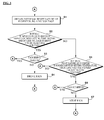
- FIG. 3 is a flow chart illustrating a method for controlling temperature of an inverter system by controlling a fan according to an exemplary embodiment of the present disclosure.
- the controller (160) may obtain an internal temperature and a DC-link voltage of the inverter (110) (S1).
- the controller (160) may determine whether the internal temperature is above a fan drive setting temperature and the DC-link voltage is above a fan drive setting voltage (S2).
- the controller (160) may determine whether the fan (150) is being driven (S3), when a condition where the internal temperature is above a fan drive setting temperature and the DC-link voltage is above a fan drive setting voltage is satisfied, in the result of the determination in step S2.
- the controller may output a fan driving control signal for driving the fan (150) to the fan (150) (S4), when the fan (150) is not being driven, in the result of the determination in step S3.
- the controller (160) may determine whether the internal temperature is under a fan stop setting temperature or the DC-link voltage is under a fan stop setting voltage (S5), when the condition where the internal temperature is above a fan drive setting temperature and the DC-link voltage is above a fan drive setting voltage is not satisfied, in the result of the determination in step S2.
- the controller (160) may determine whether the fan (150) is stopped (S6), when at least one of the two conditions where the internal temperature is under a fan stop setting temperature or the DC-link voltage is under a fan stop setting voltage is satisfied, in the result of the determination in step S5.
- the controller (160) may output a fan stopping control signal for stopping the fan (150) being driven to the fan (150) (S7), when the fan (150) is not stopped, in the result of the determination in step S6.
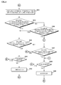
- FIG. 4 is a flow chart illustrating a method for controlling temperature of an inverter system by controlling a fan according to an exemplary embodiment of the present disclosure, particularly is an example of applying the temperature control method of an inverter system illustrated in FIG.3 , when the fan (150) is stopped.
- the controller (160) may obtain an internal temperature and a DC-link voltage of the inverter (110) (S12), in a state where the fan (150) is stopped (S11).
- the controller (160) may determine whether the internal temperature of the inverter (110) is above the fan drive setting temperature and the DC-link voltage is above the fan drive setting voltage (S13).
- the controller (160) may output a fan driving control signal for driving the stopped fan (150) to the fan (150) (S14), when a condition where the internal temperature is above a fan drive setting temperature and the DC-link voltage is above a fan drive setting voltage is satisfied, in the result of the determination in step S 13.
- controller (160) may maintain the fan (150) stopped (S15), when the condition where the internal temperature is above a fan drive setting temperature and the DC-link voltage is above a fan drive setting voltage is satisfied, in the result of the determination in step S 13.
- FIG. 5 is a flow chart illustrating a method for controlling temperature of an inverter system by controlling a fan according to an exemplary embodiment of the present disclosure, particularly is an example of applying the temperature control method of an inverter system illustrated in FIG.3 , when the fan (150) is being driven.
- the controller (160) may obtain an internal temperature and a DC-link voltage of the inverter (110) (S22), in a state where the fan (150) is stopped (S21).
- the controller (160) may determine whether the internal temperature of the inverter (110) is above the fan drive setting temperature and the DC-link voltage is above the fan drive setting voltage (S23).
- the controller (160) may output a fan driving control signal for maintaining the fan (150) being driven to the fan (150) (S24), when a condition where the internal temperature is above a fan drive setting temperature and the DC-link voltage is above a fan drive setting voltage is satisfied, in the result of the determination in step S23.
- the controller (160) may determine whether the internal temperature is under a fan stop setting temperature or the DC-link voltage is under a fan stop setting voltage (S25), when the condition where the internal temperature is above a fan drive setting temperature and the DC-link voltage is above a fan drive setting voltage is not satisfied, in the result of the determination in step S23.
- the controller (160) may output a fan stopping control signal for stopping the fan (150) being driven to the fan (150) (S26), when at least one of the two conditions where the internal temperature is under a fan stop setting temperature or the DC-link voltage is under a fan stop setting voltage is satisfied" in the result of the determination in step S25.
- the controller (160) may output a fan driving control signal for maintaining the fan (150) being driven to the fan (150) (S24), when none of the two conditions is satisfied, in the result of the determination in step S25.
- FIG. 6 is a flow chart illustrating a method for controlling temperature of an inverter system by controlling a fan according to another exemplary embodiment of the present disclosure.
- the controller (160) may obtain an internal temperature and a DC-link voltage of the inverter (110) (S31).
- the controller (160) may determine whether the internal temperature of the inverter (110) is above the fan drive setting temperature (S32).
- the controller (160) may determine whether and the DC-link voltage is above the fan drive setting voltage (S33), when the internal temperature is determined to be above the fan drive setting temperature, in the result of the determination in step S32.
- the controller (160) may determine whether the fan (150) is being driven (S34), when the DC-link voltage is determined to be above the fan drive setting voltage, in the result of the determination in step S33.
- the controller may output a fan driving control signal for driving the fan (150) to the fan (150) (S35), when the fan (150) is not being driven, in the result of the determination in step S34.
- controller (160) may determine whether the internal temperature of the inverter (110) is above the fan stop setting temperature (S36), when the internal temperature of the inverter (110) is not determined to be above the fan drive setting temperature, in the result of determination in step S32.
- the controller (160) may determine whether the fan (150) is stopped (S38), when the internal temperature of the inverter (110) is not determined to be above the fan stop setting temperature, in the result of the determination in step S36.
- the controller (160) may output a fan stopping control signal for stopping the fan (150) in driving to the fan (150) (S39), when the fan (150) is not determined to be stopped, in the result of the determination in step S38.
- the controller (160) may determine whether the DC-link voltage is above the fan stop setting voltage (S37), when the DC-link voltage is not determined to be above the fan drive setting voltage, in the result of the determination in step S33.
- the controller (160) may determine whether the fan (150) is stopped (S38), when the condition where the DC-link voltage is above the fan stop setting voltage is not satisfied, in the result of the determination in step S37.
- the controller (160) may output a fan stopping control signal for stopping the fan (150) being driven to the fan (150) (S39), when the fan (150) is not determined to be stopped, in the result of the determination in step S38.
- FIG. 7 is a flow chart illustrating a method for controlling temperature of an inverter system by controlling a fan according to another exemplary embodiment of the present disclosure, particularly is an example of applying the temperature control method of an inverter system illustrated in FIG.6 , when the fan (150) is stopped.
- the controller (160) may obtain an internal temperature and a DC-link voltage of the inverter (110) (S42), in a state where the fan (150) is stopped (S41).
- the controller (160) may determine whether the internal temperature of the inverter (110) is above the fan drive setting temperature (S43).
- the controller (160) may determine whether the DC-link voltage is above the fan drive setting voltage (S44), when the internal temperature of the inverter (110) is determined to be above the fan drive setting voltage, in the result of the determination in step S43.
- the controller (160) may output a fan drive control signal for driving the stopped fan (150) to the fan (150) (S45), when the DC-link voltage is determined to be above the fan drive setting voltage, in the result of the determination in step S44.
- the controller (160) may output a fan stopping control signal for maintaining the fan (150) stopped to the fan (150) (S47), when the DC-link voltage is not determined to be above the fan drive setting voltage, in the result of the determination in step S44.
- controller (160) may determine whether the internal temperature of the inverter (110) is above the fan stop setting temperature (S46), when the internal temperature of the inverter (110) is not determined to be above the fan drive setting temperature, in the result of the determination in step S43.
- the controller (160) may output a fan stopping control signal for maintaining the fan (150) stopped to the fan (150) (S47), when the internal temperature of the inverter (110) is not determined to be above the fan stop setting temperature, in the result of the determination in step S46.
- step S44 when the internal temperature of the inverter (110) is determined to be above the fan stop setting temperature, in the result of the determination in step S46.
- FIG. 8 is a flow chart illustrating a method for controlling temperature of an inverter system by controlling a fan according to another exemplary embodiment of the present disclosure, particularly is an example of applying the temperature control method of an inverter system illustrated in FIG.6 , when the fan is being driven.
- the controller (160) may obtain an internal temperature and a DC-link voltage of the inverter (110) (S52), in a state where the fan (150) is being driven (S51).
- the controller (160) may determine whether the internal temperature of the inverter (110) is above the fan drive setting temperature (S53).
- the controller (160) may determine whether the DC-link voltage is above the fan drive setting voltage (S54), when the internal temperature of the inverter (110) is determined to be above the fan drive setting temperature, in the result of the determination in step S53.
- the controller (160) may output a fan driving control signal for maintaining the driven fan (150) still being driven to the fan (150) (S55), when the DC-link voltage is determined to be above the fan drive setting temperature, in the result of the determination in step S54.
- controller (160) may determine whether the internal temperature of the inverter (110) is above the fan stop setting temperature (S56), when the internal temperature of the inverter (110) is not determined to be above the fan drive setting temperature, in the result of the determination in step S53.
- the process may proceed to step S54, when the internal temperature of the inverter (110) is determined to be above the fan stop setting temperature, in the result of the determination in step S56.
- the controller (160) may output a fan stopping control signal for stopping the fan (150) in driving to the fan (150) (S58).
- controller (160) may determine whether the DC-link voltage is above the fan stop setting voltage (S57), when the DC-link voltage is not determined to be above the fan drive setting signal, in the result of the determination in step S54.
- the controller (160) may output a fan stopping control signal for stopping the fan (150) in driving to the fan (150) (S58), when a condition where the DC-link voltage is above the fan stop setting voltage is not satisfied, in the result of the determination in step S57.
- the controller (160) may output a fan stopping control signal for maintaining the fan (150) still being driven to the fan (150) (S55), when a condition where the DC-link voltage is above the fan stop setting voltage is not satisfied, in the result of the determination in step S57.
- the step of outputting the fan driving control signal to the fan may be realized by including: determining whether the internal temperature is above a predetermined fan driving setting temperature; determining whether the DC-link voltage is above a predetermined fan driving setting voltage, when the internal temperature is determined to be above the predetermined fan driving setting temperature; and outputting a fan driving control signal for driving the fan or maintaining the fan being driven to the fan, when the DC-link voltage is determined to be above a predetermined fan drive setting voltage.
- the step of outputting the fan driving control signal to the fan may be realized by including: determining whether the DC-link voltage is above a predetermined fan driving setting voltage; determining whether the internal temperature is above a predetermined fan driving setting temperature, when the DC-link voltage is determined to be above the predetermined fan driving setting voltage; and outputting a fan driving control signal for driving the fan or maintaining the fan being driven to the fan, when the internal temperature is determined to be above a predetermined fan drive setting temperature.
Landscapes
- Engineering & Computer Science (AREA)
- Microelectronics & Electronic Packaging (AREA)
- Physics & Mathematics (AREA)
- Thermal Sciences (AREA)
- General Physics & Mathematics (AREA)
- Automation & Control Theory (AREA)
- General Engineering & Computer Science (AREA)
- Inverter Devices (AREA)
- Cooling Or The Like Of Electrical Apparatus (AREA)
Abstract
Description
- The present disclosure relates to a temperature control method of an inverter system by controlling a fan. More specifically, the present disclosure relates to a temperature control method of an inverter system by controlling a fan to suppress temperature increase in a SMPS (Switched-Mode Power Supply) and peripherals by controlling a fan when the inverter is stopped after inputting electrical power to the inverter.
- An inverter is a device to control torque and speed of a motor. There have been introduced various motor speed controlling methods, some of which representative methods are the first voltage control method and the frequency control method. The inverter may be used for, such as efficiency control, power factor control, etc. In addition, the inverter may also be used by being applied to, such as a preliminary power supply, an uninterruptible power supply for a computer, direct current transmission, etc.
- Purposes of using the inverter are for process control, factory automation, and energy conservation. For example, in the case of a heating furnace blower, an inverter may control speed of the blower according to types or quantity of products. Temperature inside the heating furnace may be controlled as the optimal temperature by controlling air volume of the blower, and the quality of the product can be improved as well. Thereby, a great retrenchment in energy consumption can be obtained. Currently, researches for technology to efficiently control an inverter when an urgent situation such as instantaneous blackout occurs are conducted actively.
- An inverter includes an SMPS (Switched-Mode Power Supply) inside thereof. The SMPS is a power supply including a switching regulator to efficiently convert electric power. The SMPS becomes a heat source to increase temperature of internal components of the inverter, when the inverter is not driven while being inputted with electric power.
- Temperature of the SMPS increases as DC (Direct Current)-link voltage and switching frequency grows larger. Load of the SMPS increases and internal convection of the inverter occurs to suppress temperature increase in peripherals due to the SMPS, when the invert and the fan start to be driven.
- A heat sink at a lower part of the invert can prevent a three-leg switch at an output part of the inverter from an excessive temperature increase. However, the heat sink may not suppress temperature increase of the SMPS. Temperature of the SMPS and the peripherals comes to increase due to load reduction of the SMPS and deterioration in internal convection of the inverter, when the inverter and the fan are stopped.
- Conventional conditions for driving the fan are divided, such as when the inverter is being driven, when temperature of a switch module at an output part is above a predetermined value, or constant drive.
- In the case of small capacity inverters in which internal space is confined and has a poor condition for convection, temperature of the peripherals comes to increase due to the SMPS when the inverter is stopped. However, there is no method to suppress the peripheral temperature increase but to constantly drive the fan.
- The temperature increase of SMPS may be lessened by inserting a dumnry load, when using a method to change a switching frequency according to the load of SMPS. However, the method is suitable for a product in which internal space is confined because additional components are required. Furthermore, effect of such method is not significant.
- Meanwhile, the temperature increase of peripherals may be suppressed by constantly driving the fan when the inverter is stopped. However, there is a disadvantage in that a certain amount of electric power should be constantly consumed.
- A technical challenge that the present disclosure intends to achieve is, to provide a temperature control method of an inverter system by using a fan control to suppress temperature increase in a SMPS and peripherals by improving the environment for convection in the inverter through the fan control.
- Technical challenges of the present disclosure are not limited to the above-mentioned technical challenges. Other technical challenges which are not mentioned will be clearly understandable for persons who skilled in the technical field to which exemplary embodiments suggested from the following description belong.
- In a general aspect of the present disclosure, there is provided a method for controlling temperature of an inverter system having an inverter and a cooling fan, the method comprising: obtaining an internal temperature of the inverter and a DC (Direct Current)-link voltage of the inverter; and outputting a fan driving control signal for driving the fan or maintaining the fan being driven to the fan, when the internal temperature is above a predetermined fan drive setting temperature and the DC-link voltage is above a predetermined fan drive setting voltage.
- In some exemplary embodiments of the present disclosure, the step of outputting the fan driving control signal to the fan may include: outputting a fan driving control signal for driving the fan to the fan, when the internal temperature is above a predetermined fan drive setting temperature and the DC-link voltage is above a predetermined fan drive setting voltage, in a state where the fan is stopped.
- In some exemplary embodiments of the present disclosure, the step of outputting the fan driving control signal to the fan may include: outputting a fan driving control signal for maintaining the fan being driven to the fan, when the internal temperature is above a predetermined fan drive setting temperature and the DC-link voltage is above a predetermined fan drive setting voltage, in a state where the fan is being driven.
- In some exemplary embodiments of the present disclosure, the step of outputting the fan driving control signal to the fan may include: determining whether the internal temperature is above the predetermined fan driving setting temperature; determining whether the DC-link voltage is above the predetermined fan driving setting voltage, when the internal temperature is determined to be above the predetermined fan driving setting temperature; and outputting the fan driving control signal for driving the fan or maintaining the fan being driven to the fan, when the DC-link voltage is determined to be above a predetermined fan drive setting voltage.
- In some exemplary embodiments of the present disclosure, the step of outputting the fan driving control signal to the fan may include: outputting the fan driving control signal for driving the fan to the fan when the fan is stopped, when the DC-link voltage is determined to be above the predetermined fan drive setting voltage.
- In some exemplary embodiment of the present disclosure, the step of outputting the fan driving control signal to the fan may include: outputting the fan driving control signal for maintaining the fan being driven to the fan when the fan is being driven, when the DC-link voltage is determined to be above the predetermined fan drive setting voltage.
- In some exemplary embodiment of the present disclosure, the step of outputting the fan driving control signal to the fan may include: determining whether the DC-link voltage is above the predetermined fan driving setting voltage; determining whether the internal temperature is above the predetermined fan driving setting temperature, when the DC-link voltage is determined to be above the predetermined fan driving setting voltage; and outputting the fan driving control signal for driving the fan or maintaining the fan being driven to the fan, when the internal temperature is determined to be above the predetermined fan drive setting temperature.
- In some exemplary embodiment of the present disclosure, the step of outputting the fan driving control signal to the fan may include: outputting a fan driving control signal for driving the fan to the fan when the fan is stopped, when the internal temperature is determined to be above a predetermined fan drive setting temperature.
- In some exemplary embodiment of the present disclosure, the step of outputting the fan driving control signal to the fan may include: outputting a fan driving control signal for maintain the fan being driven to the fan, when the internal temperature is determined to be above the predetermined fan drive setting temperature, in the state where the fan is being driven.
- In some exemplary embodiment of the present disclosure, the method for controlling temperature of an inverter system by using a fan control may further include: outputting a fan stopping control signal for stopping the fan to the fan in response to the fan driving control signal, when the internal temperature is determined to be under a predetermined fan stop setting temperature or the DC-link voltage is determined to be under a predetermined fan stop setting voltage, in the state where the fan is being driven.
- In some exemplary embodiment of the present disclosure, the fan stop setting temperature may be predetermined to be under the fan drive setting temperature, and the fan stop setting voltage may be predetermined to be under the fan drive setting temperature.
- According to an exemplary embodiment of the present disclosure, temperature increase of the SMPS and the peripherals may be suppressed by improving the environment for convection in the inverter through the fan control. Driving the fan by using an internal temperature and a DC-link voltage as control factors can suppress the temperature increase of peripherals more efficiently than constantly driving the fan.
-
-
FIG. 1 is a block diagram of an inverter system according to an exemplary embodiment of the present disclosure. -
FIG. 2 is a view illustrating a fan drive setting temperature and a fan stop setting temperature in an inverter system according to an exemplary embodiment of the present disclosure. -
FIG. 3 is a flow chart illustrating a method for controlling temperature of an inverter system by controlling a fan according to an exemplary embodiment of the present disclosure. -
FIG. 4 is a flow chart illustrating a method for controlling temperature of an inverter system by controlling a fan according to an exemplary embodiment of the present disclosure, particularly is an example of applying the temperature control method of an inverter system illustrated inFIG.3 , when the fan is stopped. -
FIG. 5 is a flow chart illustrating a method for controlling temperature of an inverter system by controlling a fan according to an exemplary embodiment of the present disclosure, particularly is an example of applying the temperature control method of an inverter system illustrated inFIG.3 , when the fan is being driven. -
FIG. 6 is a flow chart illustrating a method for controlling temperature of an inverter system by controlling a fan according to another exemplary embodiment of the present disclosure. -
FIG. 7 is a flow chart illustrating a method for controlling temperature of an inverter system by controlling a fan according to another exemplary embodiment of the present disclosure, particularly is an example of applying the temperature control method of an inverter system illustrated inFIG.6 , when the fan is stopped. -
FIG. 8 is a flow chart illustrating a method for controlling temperature of an inverter system by controlling a fan according to another exemplary embodiment of the present disclosure, particularly is an example of applying the temperature control method of an inverter system illustrated inFIG.6 , when the fan is being driven. - Hereinafter, reference will now be made in detail to the embodiments of the present disclosure, examples of which are illustrated in the accompanying drawings. The present disclosure may, however, be embodied in many different forms and should not be construed as being limited to the embodiments set forth herein; rather, that alternate embodiments included in other retrogressive inventions or falling within the spirit and scope of the present disclosure will fully convey the concept of the invention to those skilled in the art.
- Although the terms used in the present disclosure are selected from generally known and used terms, some of the terms mentioned in the description of the present disclosure have been selected by the applicant at his or her discretion, the detailed meanings of which are described in relevant parts of the description herein. Therefore, the present disclosure shall be understood, not simply by the general terms used but by the meaning of each term lying within.
- That is, in the following description herein, the term "including" or "comprising" does not exclude the presence of elements or steps other than those listed.
-
FIG. 1 is a block diagram of an inverter system according to an exemplary embodiment of the present disclosure. - Referring to
FIG. 1 , an inverter system (100) according to an exemplary embodiment of the present disclosure may include an inverter (110), a SMPS (120), a DC-link unit (130), a heat sink (140), a fan (150), and a controller (160). - The SMPS (Switched-Mode Power Supply) (120) supplies electric power to the inverter (110), and may include a switching regulator to efficiently convert the supplied electric power. The SMPS may become a heat source to increase temperature of internal components of the inverter, when the inverter (110) is not driven while being inputted with electric power. Temperature of the SMPS(120) increases as DC (Direct Current)-link voltage and switching frequency grows larger.
- An SMPS of which switching frequency is variable according to load may be used as the SMPS (120). An additional effect of suppressing temperature increase may be expected when using the SMPS of variable switching frequency according to load, since load of the SMPS (120) increases when the fan (150) is driven.
- In the case of the SMPS (120) of variable switching frequency according to load, the electric power to drive the fan may become the load of the SMPS (120) to reduce switching frequency and to suppress temperature increase of the SMPS (120).
- The DC-link unit (130) converts alternate current electric power rectified by being supplied to the inverter (110) to direct current electric power. The DC-link unit (130) may include a condenser for smoothing the rectified electric power.
- The heat sink (140) prevents temperature increase of the inverter (110) or the SMPS (120), by being installed at a lower part of the inverter (110) or the SMPS (120), or by being installed adjacent to the inverter (110) or the SMPS (120).
- The fan (150) is installed in order to prevent temperature increase generated by the inverter (110) and the SMPS (120) and to generate a convection flow for cooling. The fan (150) is driven by a fan driving control signal of the controller (160), and stopped by a fan stopping control signal.
- The controller (160) outputs a fan driving control signal for driving the fan (150) or maintaining the driven fan (150) being driven to the fan (150) after applying an electric power to the inverter (110), or outputs a fan stopping control signal for stopping the fan (150) being driven or maintaining the stopped fan (150) being still stopped.
- The controller (160) may use an internal temperature of the inverter (110) and a DC-link voltage of the DC-link unit (130) as control factors to determine whether the fan (150) is to be driven.
- The controller (160) includes a predetermined fan drive setting temperature to drive the stopped fan (150) by being compared to the internal temperature of the inverter (110). The controller (160) may determine that a first condition to drive the fan (150) is satisfied, when the internal temperature of the inverter (110) measured inside the inverter (110) is above the fan driving setting temperature.
- The controller (160) includes a predetermined fan drive setting voltage to drive the stopped fan (150) by being compared to the DC-link voltage of the inverter (110). The controller (160) may determine that a first condition to drive the fan (150) is satisfied, when the measured DC-link voltage of the inverter (110) is above the fan driving setting voltage.
- The controller (160) may output a fan driving control signal for driving the fan (150) the fan (150), when both of the fist and the second conditions are satisfied, that is, when the internal temperature and the DC-link voltage are above the predetermined fan drive setting temperature and the predetermined fan drive setting voltage, respectively.
- Convection may occur in the inverter (110) to suppress temperature increase of the SMPS (120) and the peripherals, when the fan (150) is driven by the fan driving control signal outputted from the controller (160).
- The controller (160) includes a fan stop setting temperature and a fan stop setting voltage as well as the fan drive setting temperature and the fan drive setting voltage, in order to determine whether the fan (150) is to be driven or stopped.
- The controller (160) outputs a fan stopping control signal for stopping the fan (150) to the fan (150), when the internal temperature is determined to be under the predetermined fan stop setting temperature or the DC-link voltage is determined to be under the predetermined fan stop setting voltage.
- Here, the fan stop setting temperature may be predetermined to be under the fan drive setting temperature to prevent drive/stop operation of the fan (150) be frequently repeated.
- The fan (150) is driven when the internal temperature is above the predetermined fan drive setting temperature and the DC-link voltage is above the predetermined fan drive setting voltage. The temperature increase of the peripherals may be effectively suppressed due to the improved internal convection environment of the inverter (110) through the drive of the fan (150).
-
FIG. 2 is a view illustrating a fan drive setting temperature and a fan stop setting temperature in an inverter system according to an exemplary embodiment of the present disclosure. - Referring to
FIG. 2 , the fan stop setting temperature (Ts) is predetermined to be under the fan drive setting temperature (Td). - The controller (160) outputs a fan driving control signal for driving the stopped fan (150) to the fan (150), when the DC-link voltage is determined to be above the fan drive setting voltage, by determining whether the DC-link voltage is above the fan driving setting voltage, when a first point of time (td) where the internal temperature (Ti) becomes above the fan drive setting temperature (Td) arrives while the fan (150) is stopped.
- Meanwhile, the controller (160) outputs a fan stopping control signal for stopping the fan (150) being driven to the fan (150), when a second point of time (ts) where the internal temperature (Ti) becomes under the fan stop setting temperature (Ts) arrives while the fan (150) is being driven after the first point of time (td) has passed. Of course, the controller (160) may output a fan stopping control signal for stopping the fan (150) being driven to the fan (150), when the DC-link voltage becomes under the fan stop setting voltage, even though the second point of time (ts) where the internal temperature (Ti) becomes under the fan stop setting temperature (Ts) does not arrive while the fan (150) is being driven after the first point of time (td) has passed.
-
FIG. 3 is a flow chart illustrating a method for controlling temperature of an inverter system by controlling a fan according to an exemplary embodiment of the present disclosure. - Referring to
FIG. 3 , the controller (160) may obtain an internal temperature and a DC-link voltage of the inverter (110) (S1). - The controller (160) may determine whether the internal temperature is above a fan drive setting temperature and the DC-link voltage is above a fan drive setting voltage (S2).
- The controller (160) may determine whether the fan (150) is being driven (S3), when a condition where the internal temperature is above a fan drive setting temperature and the DC-link voltage is above a fan drive setting voltage is satisfied, in the result of the determination in step S2.
- The controller may output a fan driving control signal for driving the fan (150) to the fan (150) (S4), when the fan (150) is not being driven, in the result of the determination in step S3.
- Meanwhile, the controller (160) may determine whether the internal temperature is under a fan stop setting temperature or the DC-link voltage is under a fan stop setting voltage (S5), when the condition where the internal temperature is above a fan drive setting temperature and the DC-link voltage is above a fan drive setting voltage is not satisfied, in the result of the determination in step S2.
- The controller (160) may determine whether the fan (150) is stopped (S6), when at least one of the two conditions where the internal temperature is under a fan stop setting temperature or the DC-link voltage is under a fan stop setting voltage is satisfied, in the result of the determination in step S5.
- The controller (160) may output a fan stopping control signal for stopping the fan (150) being driven to the fan (150) (S7), when the fan (150) is not stopped, in the result of the determination in step S6.
-
FIG. 4 is a flow chart illustrating a method for controlling temperature of an inverter system by controlling a fan according to an exemplary embodiment of the present disclosure, particularly is an example of applying the temperature control method of an inverter system illustrated inFIG.3 , when the fan (150) is stopped. - Referring to
FIG. 4 , the controller (160) may obtain an internal temperature and a DC-link voltage of the inverter (110) (S12), in a state where the fan (150) is stopped (S11). - The controller (160) may determine whether the internal temperature of the inverter (110) is above the fan drive setting temperature and the DC-link voltage is above the fan drive setting voltage (S13).
- The controller (160) may output a fan driving control signal for driving the stopped fan (150) to the fan (150) (S14), when a condition where the internal temperature is above a fan drive setting temperature and the DC-link voltage is above a fan drive setting voltage is satisfied, in the result of the determination in
step S 13. - Meanwhile, the controller (160) may maintain the fan (150) stopped (S15), when the condition where the internal temperature is above a fan drive setting temperature and the DC-link voltage is above a fan drive setting voltage is satisfied, in the result of the determination in
step S 13. -
FIG. 5 is a flow chart illustrating a method for controlling temperature of an inverter system by controlling a fan according to an exemplary embodiment of the present disclosure, particularly is an example of applying the temperature control method of an inverter system illustrated inFIG.3 , when the fan (150) is being driven. - Referring to
FIG. 5 , the controller (160) may obtain an internal temperature and a DC-link voltage of the inverter (110) (S22), in a state where the fan (150) is stopped (S21). - The controller (160) may determine whether the internal temperature of the inverter (110) is above the fan drive setting temperature and the DC-link voltage is above the fan drive setting voltage (S23).
- The controller (160) may output a fan driving control signal for maintaining the fan (150) being driven to the fan (150) (S24), when a condition where the internal temperature is above a fan drive setting temperature and the DC-link voltage is above a fan drive setting voltage is satisfied, in the result of the determination in step S23.
- Meanwhile, the controller (160) may determine whether the internal temperature is under a fan stop setting temperature or the DC-link voltage is under a fan stop setting voltage (S25), when the condition where the internal temperature is above a fan drive setting temperature and the DC-link voltage is above a fan drive setting voltage is not satisfied, in the result of the determination in step S23.
- The controller (160) may output a fan stopping control signal for stopping the fan (150) being driven to the fan (150) (S26), when at least one of the two conditions where the internal temperature is under a fan stop setting temperature or the DC-link voltage is under a fan stop setting voltage is satisfied" in the result of the determination in step S25.
- The controller (160) may output a fan driving control signal for maintaining the fan (150) being driven to the fan (150) (S24), when none of the two conditions is satisfied, in the result of the determination in step S25.
-
FIG. 6 is a flow chart illustrating a method for controlling temperature of an inverter system by controlling a fan according to another exemplary embodiment of the present disclosure. - Referring to
FIG. 6 , the controller (160) may obtain an internal temperature and a DC-link voltage of the inverter (110) (S31). - The controller (160) may determine whether the internal temperature of the inverter (110) is above the fan drive setting temperature (S32).
- The controller (160) may determine whether and the DC-link voltage is above the fan drive setting voltage (S33), when the internal temperature is determined to be above the fan drive setting temperature, in the result of the determination in step S32.
- The controller (160) may determine whether the fan (150) is being driven (S34), when the DC-link voltage is determined to be above the fan drive setting voltage, in the result of the determination in step S33.
- The controller may output a fan driving control signal for driving the fan (150) to the fan (150) (S35), when the fan (150) is not being driven, in the result of the determination in step S34.
- Meanwhile, the controller (160) may determine whether the internal temperature of the inverter (110) is above the fan stop setting temperature (S36), when the internal temperature of the inverter (110) is not determined to be above the fan drive setting temperature, in the result of determination in step S32.
- The controller (160) may determine whether the fan (150) is stopped (S38), when the internal temperature of the inverter (110) is not determined to be above the fan stop setting temperature, in the result of the determination in step S36.
- The controller (160) may output a fan stopping control signal for stopping the fan (150) in driving to the fan (150) (S39), when the fan (150) is not determined to be stopped, in the result of the determination in step S38.
- The controller (160) may determine whether the DC-link voltage is above the fan stop setting voltage (S37), when the DC-link voltage is not determined to be above the fan drive setting voltage, in the result of the determination in step S33.
- The controller (160) may determine whether the fan (150) is stopped (S38), when the condition where the DC-link voltage is above the fan stop setting voltage is not satisfied, in the result of the determination in step S37.
- The controller (160) may output a fan stopping control signal for stopping the fan (150) being driven to the fan (150) (S39), when the fan (150) is not determined to be stopped, in the result of the determination in step S38.
-
FIG. 7 is a flow chart illustrating a method for controlling temperature of an inverter system by controlling a fan according to another exemplary embodiment of the present disclosure, particularly is an example of applying the temperature control method of an inverter system illustrated inFIG.6 , when the fan (150) is stopped. - Referring to
FIG. 7 , the controller (160) may obtain an internal temperature and a DC-link voltage of the inverter (110) (S42), in a state where the fan (150) is stopped (S41). - The controller (160) may determine whether the internal temperature of the inverter (110) is above the fan drive setting temperature (S43).
- The controller (160) may determine whether the DC-link voltage is above the fan drive setting voltage (S44), when the internal temperature of the inverter (110) is determined to be above the fan drive setting voltage, in the result of the determination in step S43.
- The controller (160) may output a fan drive control signal for driving the stopped fan (150) to the fan (150) (S45), when the DC-link voltage is determined to be above the fan drive setting voltage, in the result of the determination in step S44.
- The controller (160) may output a fan stopping control signal for maintaining the fan (150) stopped to the fan (150) (S47), when the DC-link voltage is not determined to be above the fan drive setting voltage, in the result of the determination in step S44.
- Meanwhile, the controller (160) may determine whether the internal temperature of the inverter (110) is above the fan stop setting temperature (S46), when the internal temperature of the inverter (110) is not determined to be above the fan drive setting temperature, in the result of the determination in step S43.
- The controller (160) may output a fan stopping control signal for maintaining the fan (150) stopped to the fan (150) (S47), when the internal temperature of the inverter (110) is not determined to be above the fan stop setting temperature, in the result of the determination in step S46.
- Meanwhile, the process may proceed to step S44, when the internal temperature of the inverter (110) is determined to be above the fan stop setting temperature, in the result of the determination in step S46.
-
FIG. 8 is a flow chart illustrating a method for controlling temperature of an inverter system by controlling a fan according to another exemplary embodiment of the present disclosure, particularly is an example of applying the temperature control method of an inverter system illustrated inFIG.6 , when the fan is being driven. - Referring to
FIG. 8 , the controller (160) may obtain an internal temperature and a DC-link voltage of the inverter (110) (S52), in a state where the fan (150) is being driven (S51). - The controller (160) may determine whether the internal temperature of the inverter (110) is above the fan drive setting temperature (S53).
- The controller (160) may determine whether the DC-link voltage is above the fan drive setting voltage (S54), when the internal temperature of the inverter (110) is determined to be above the fan drive setting temperature, in the result of the determination in step S53.
- The controller (160) may output a fan driving control signal for maintaining the driven fan (150) still being driven to the fan (150) (S55), when the DC-link voltage is determined to be above the fan drive setting temperature, in the result of the determination in step S54.
- Meanwhile, the controller (160) may determine whether the internal temperature of the inverter (110) is above the fan stop setting temperature (S56), when the internal temperature of the inverter (110) is not determined to be above the fan drive setting temperature, in the result of the determination in step S53.
- The process may proceed to step S54, when the internal temperature of the inverter (110) is determined to be above the fan stop setting temperature, in the result of the determination in step S56.
- The controller (160) may output a fan stopping control signal for stopping the fan (150) in driving to the fan (150) (S58).
- Meanwhile, the controller (160) may determine whether the DC-link voltage is above the fan stop setting voltage (S57), when the DC-link voltage is not determined to be above the fan drive setting signal, in the result of the determination in step S54.
- The controller (160) may output a fan stopping control signal for stopping the fan (150) in driving to the fan (150) (S58), when a condition where the DC-link voltage is above the fan stop setting voltage is not satisfied, in the result of the determination in step S57.
- The controller (160) may output a fan stopping control signal for maintaining the fan (150) still being driven to the fan (150) (S55), when a condition where the DC-link voltage is above the fan stop setting voltage is not satisfied, in the result of the determination in step S57.
- The abovementioned exemplary embodiments are intended to be illustrative, and not to limit the scope of the claims. Many alternatives, modifications, variations, and equivalents will be apparent to those skilled in the art. The features, structures, methods, and other characteristics of the exemplary embodiments described herein may be combined in various ways to obtain additional and/or alternative exemplary embodiments. Therefore, the technical scope of the rights for the present disclosure shall be decided by the claims and equivalents thereof.
- For example, according to an exemplary embodiment of the present disclosure, the step of outputting the fan driving control signal to the fan may be realized by including: determining whether the internal temperature is above a predetermined fan driving setting temperature; determining whether the DC-link voltage is above a predetermined fan driving setting voltage, when the internal temperature is determined to be above the predetermined fan driving setting temperature; and outputting a fan driving control signal for driving the fan or maintaining the fan being driven to the fan, when the DC-link voltage is determined to be above a predetermined fan drive setting voltage.
- According to another modified exemplary embodiment of the present disclosure, the step of outputting the fan driving control signal to the fan may be realized by including: determining whether the DC-link voltage is above a predetermined fan driving setting voltage; determining whether the internal temperature is above a predetermined fan driving setting temperature, when the DC-link voltage is determined to be above the predetermined fan driving setting voltage; and outputting a fan driving control signal for driving the fan or maintaining the fan being driven to the fan, when the internal temperature is determined to be above a predetermined fan drive setting temperature.
Claims (11)
- A method for controlling temperature of an inverter system having an inverter and a cooling fan, the method comprising:obtaining an internal temperature of the inverter and a DC (Direct Current)-link voltage of the inverter(S1); andoutputting a fan driving control signal for driving the fan or maintaining the fan being driven to the fan, when the internal temperature is above a predetermined fan drive setting temperature and the DC-link voltage is above a predetermined fan drive setting voltage(S2, S3, S4, S5, S6, S7).
- The method of claim 1, wherein the step of outputting the fan driving control signal to the fan includes:outputting a fan driving control signal for driving the fan to the fan, when the internal temperature is above a predetermined fan drive setting temperature and the DC-link voltage is above a predetermined fan drive setting voltage, in a state where the fan is stopped(S13, S14).
- The method of claim 1 or 2, wherein the step of outputting the fan driving control signal to the fan includes:outputting a fan driving control signal for maintaining the fan being driven to the fan, when the internal temperature is above a predetermined fan drive setting temperature and the DC-link voltage is above a predetermined fan drive setting voltage, in a state where the fan is being driven(S23, S24).
- The method of any one of claims 1 to 3, wherein the step of outputting the fan driving control signal to the fan includes:determining whether the internal temperature is above the predetermined fan driving setting temperature(S31);determining whether the DC-link voltage is above the predetermined fan driving setting voltage, when the internal temperature is determined to be above the predetermined fan driving setting temperature(S32); andoutputting the fan driving control signal for driving the fan or maintaining the fan being driven to the fan, when the DC-link voltage is determined to be above a predetermined fan drive setting voltage(S35).
- The method of claim 4, wherein the step of outputting the fan driving control signal to the fan includes:outputting the fan driving control signal for driving the fan to the fan when the fan is stopped, when the DC-link voltage is determined to be above the predetermined fan drive setting voltage(S41, S44, S45).
- The method of claim 4, wherein the step of outputting the fan driving control signal to the fan includes:outputting the fan driving control signal for maintaining the fan being driven to the fan when the fan is being driven, when the DC-link voltage is determined to be above the predetermined fan drive setting voltage(S51, S54, S55).
- The method of any one of claims 1 to 6, wherein the step of outputting the fan driving control signal to the fan includes:determining whether the DC-link voltage is above the predetermined fan driving setting voltage(S13, S23);determining whether the internal temperature is above the predetermined fan driving setting temperature, when the DC-link voltage is determined to be above the predetermined fan driving setting voltage(S 13, S23); andoutputting the fan driving control signal for driving the fan or maintaining the fan being driven to the fan, when the internal temperature is determined to be above the predetermined fan drive setting temperature(S14, S24).
- The method of claim 7, wherein the step of outputting the fan driving control signal to the fan includes:outputting the fan driving control signal for driving the fan to the fan, when the internal temperature is determined to be above the predetermined fan drive setting temperature, in the state where the fan is stopped(S11, S13, S14).
- The method of claim 7, wherein the step of outputting the fan driving control signal to the fan includes:outputting a fan driving control signal for maintain the fan being driven to the fan, when the internal temperature is determined to be above the predetermined fan drive setting temperature, in the state where the fan is being driven(S21, S23, S24).
- The method of any one of claims 1 to 9, further comprising:outputting a fan stopping control signal for stopping the fan to the fan in response to the fan driving control signal, when the internal temperature is determined to be under a predetermined fan stop setting temperature or the DC-link voltage is determined to be under a predetermined fan stop setting voltage, in the state the fan is being driven(S21, S25, S26).
- The method of any one of claims 10, wherein
the fan stop setting temperature is predetermined to be under the fan drive setting temperature, and
the fan stop setting voltage is predetermined to be under the fan drive setting temperature.
Applications Claiming Priority (1)
| Application Number | Priority Date | Filing Date | Title |
|---|---|---|---|
| KR1020140072594A KR20150144024A (en) | 2014-06-16 | 2014-06-16 | Method for controlling temperature of inverter system by contolling a fan |
Publications (2)
| Publication Number | Publication Date |
|---|---|
| EP2958412A1 true EP2958412A1 (en) | 2015-12-23 |
| EP2958412B1 EP2958412B1 (en) | 2020-01-22 |
Family
ID=53397863
Family Applications (1)
| Application Number | Title | Priority Date | Filing Date |
|---|---|---|---|
| EP15171432.6A Active EP2958412B1 (en) | 2014-06-16 | 2015-06-10 | Method for controlling temperature of inverter system by controlling a fan |
Country Status (6)
| Country | Link |
|---|---|
| US (1) | US9867314B2 (en) |
| EP (1) | EP2958412B1 (en) |
| JP (1) | JP6027191B2 (en) |
| KR (1) | KR20150144024A (en) |
| CN (1) | CN105183033B (en) |
| ES (1) | ES2784267T3 (en) |
Families Citing this family (6)
| Publication number | Priority date | Publication date | Assignee | Title |
|---|---|---|---|---|
| KR102031688B1 (en) * | 2014-06-05 | 2019-11-08 | 리탈 게엠베하 운트 코.카게 | Cooling device, in particular for cooling components housed in a switchgear cabinet, corresponding use, and corresponding method |
| KR102514585B1 (en) * | 2016-02-26 | 2023-03-27 | 엘에스일렉트릭(주) | Digital protection relay and controlling method thereof |
| KR102318722B1 (en) * | 2017-03-20 | 2021-10-27 | 엘에스일렉트릭(주) | managing device for cooling inverter |
| KR102126879B1 (en) * | 2018-05-09 | 2020-06-25 | 엘에스일렉트릭(주) | Method for controlling inverter |
| TWI765255B (en) * | 2020-04-23 | 2022-05-21 | 海韻電子工業股份有限公司 | fan control circuit |
| WO2022183257A1 (en) * | 2021-03-01 | 2022-09-09 | PpWEG DRIVES & CONTROLS AUTOMAÇÃO LTDA. | System and method for cooling a frequency inverter |
Citations (3)
| Publication number | Priority date | Publication date | Assignee | Title |
|---|---|---|---|---|
| US5831847A (en) * | 1997-02-05 | 1998-11-03 | Jerome Industries Corp. | Power supply with separated airflows |
| US6236184B1 (en) * | 1998-12-23 | 2001-05-22 | Hamilton Sundstrand Corporation | Variable speed cooling fan control |
| US20070147100A1 (en) * | 2005-12-28 | 2007-06-28 | Kiyomi Tashima | Frequency converting apparatus and control method for the apparatus |
Family Cites Families (11)
| Publication number | Priority date | Publication date | Assignee | Title |
|---|---|---|---|---|
| JPH054582U (en) * | 1991-04-18 | 1993-01-22 | 三菱電機株式会社 | Air conditioner inverter device |
| JPH054582A (en) | 1991-06-26 | 1993-01-14 | Hitachi Ltd | Pantograph noise reduction device |
| JP3701415B2 (en) | 1996-11-08 | 2005-09-28 | 株式会社三社電機製作所 | Power supply unit for arc welding machine |
| JP3818082B2 (en) | 2001-04-26 | 2006-09-06 | 株式会社明電舎 | Inverter |
| US7205740B1 (en) * | 2006-03-17 | 2007-04-17 | Delta Elctronics, Inc. | Fan control device for frequency converter |
| JP5270681B2 (en) | 2008-09-18 | 2013-08-21 | 株式会社三社電機製作所 | Inverter for grid connection |
| JP5454067B2 (en) | 2009-10-08 | 2014-03-26 | 東芝三菱電機産業システム株式会社 | Cooling system for power converter |
| JP2013046481A (en) | 2011-08-23 | 2013-03-04 | Hitachi Koki Co Ltd | Waveform conversion device and power supply device equipped with the same |
| WO2013103711A2 (en) * | 2012-01-03 | 2013-07-11 | General Electric Company | Ventilation control system and method for power converters |
| JP2013143830A (en) | 2012-01-11 | 2013-07-22 | Toshiba Elevator Co Ltd | Elevator controller |
| KR101423824B1 (en) | 2012-07-02 | 2014-08-13 | 주식회사 포스코아이씨티 | Water cooled inverter system and Method for controlling thereof |
-
2014
- 2014-06-16 KR KR1020140072594A patent/KR20150144024A/en not_active Ceased
-
2015
- 2015-06-10 EP EP15171432.6A patent/EP2958412B1/en active Active
- 2015-06-10 ES ES15171432T patent/ES2784267T3/en active Active
- 2015-06-12 US US14/738,729 patent/US9867314B2/en active Active
- 2015-06-15 CN CN201510446926.8A patent/CN105183033B/en active Active
- 2015-06-16 JP JP2015121170A patent/JP6027191B2/en not_active Expired - Fee Related
Patent Citations (3)
| Publication number | Priority date | Publication date | Assignee | Title |
|---|---|---|---|---|
| US5831847A (en) * | 1997-02-05 | 1998-11-03 | Jerome Industries Corp. | Power supply with separated airflows |
| US6236184B1 (en) * | 1998-12-23 | 2001-05-22 | Hamilton Sundstrand Corporation | Variable speed cooling fan control |
| US20070147100A1 (en) * | 2005-12-28 | 2007-06-28 | Kiyomi Tashima | Frequency converting apparatus and control method for the apparatus |
Also Published As
| Publication number | Publication date |
|---|---|
| EP2958412B1 (en) | 2020-01-22 |
| JP2016005432A (en) | 2016-01-12 |
| ES2784267T3 (en) | 2020-09-23 |
| US9867314B2 (en) | 2018-01-09 |
| CN105183033A (en) | 2015-12-23 |
| CN105183033B (en) | 2017-07-28 |
| US20150366104A1 (en) | 2015-12-17 |
| KR20150144024A (en) | 2015-12-24 |
| JP6027191B2 (en) | 2016-11-16 |
Similar Documents
| Publication | Publication Date | Title |
|---|---|---|
| EP2958412B1 (en) | Method for controlling temperature of inverter system by controlling a fan | |
| US9225283B2 (en) | Motor control device for switching PWM frequency to use the same | |
| CN111245323B (en) | Motor control method, device, computer-readable storage medium, and electrical equipment | |
| CN107210622B (en) | refrigerator | |
| US20150364985A1 (en) | System for operation control of inverter in emergency situation | |
| CN109357436B (en) | Variable frequency heat pump control method | |
| KR20160058074A (en) | Method for controlling temperature of inverter system by contolling a fan | |
| KR20150033654A (en) | System and method of dynamic regulation of real power to a load | |
| JP6271075B2 (en) | Inverter control device and air conditioner | |
| CN107112934B (en) | Adjustment of the drive | |
| JP5734626B2 (en) | Power supply and air conditioner | |
| JP6400529B2 (en) | Electric motor control device | |
| JP6482796B2 (en) | Motor control apparatus and method thereof | |
| KR101805131B1 (en) | Power supply for enhancing hold-up time | |
| JP5906454B2 (en) | Induction heating apparatus and control method thereof | |
| KR102411784B1 (en) | Air conditioner and controlling method thereof | |
| JP2008301653A (en) | Electric power generating system | |
| KR101236680B1 (en) | Apparatus for controlling motor drive | |
| JP6295947B2 (en) | Air conditioner | |
| JP6508782B2 (en) | Power converter and DC voltage controller | |
| CN119222749A (en) | PFC circuit and control method thereof, storage medium, electrical equipment and air conditioner | |
| KR101619884B1 (en) | Apparatus for reducing reactive power | |
| JP2010239756A (en) | DC power supply | |
| JP2011160558A (en) | Dc power supply apparatus | |
| JP2020184849A (en) | Control device, power conversion device, control method, and program |
Legal Events
| Date | Code | Title | Description |
|---|---|---|---|
| PUAI | Public reference made under article 153(3) epc to a published international application that has entered the european phase |
Free format text: ORIGINAL CODE: 0009012 |
|
| AK | Designated contracting states |
Kind code of ref document: A1 Designated state(s): AL AT BE BG CH CY CZ DE DK EE ES FI FR GB GR HR HU IE IS IT LI LT LU LV MC MK MT NL NO PL PT RO RS SE SI SK SM TR |
|
| AX | Request for extension of the european patent |
Extension state: BA ME |
|
| 17P | Request for examination filed |
Effective date: 20160623 |
|
| RBV | Designated contracting states (corrected) |
Designated state(s): AL AT BE BG CH CY CZ DE DK EE ES FI FR GB GR HR HU IE IS IT LI LT LU LV MC MK MT NL NO PL PT RO RS SE SI SK SM TR |
|
| REG | Reference to a national code |
Ref country code: DE Ref legal event code: R079 Ref document number: 602015045873 Country of ref document: DE Free format text: PREVIOUS MAIN CLASS: H05K0007200000 Ipc: G05B0015020000 |
|
| RIC1 | Information provided on ipc code assigned before grant |
Ipc: H05K 7/20 20060101ALI20190711BHEP Ipc: G05B 15/02 20060101AFI20190711BHEP |
|
| GRAP | Despatch of communication of intention to grant a patent |
Free format text: ORIGINAL CODE: EPIDOSNIGR1 |
|
| STAA | Information on the status of an ep patent application or granted ep patent |
Free format text: STATUS: GRANT OF PATENT IS INTENDED |
|
| INTG | Intention to grant announced |
Effective date: 20190916 |
|
| RAP1 | Party data changed (applicant data changed or rights of an application transferred) |
Owner name: LSIS CO., LTD. |
|
| GRAS | Grant fee paid |
Free format text: ORIGINAL CODE: EPIDOSNIGR3 |
|
| GRAA | (expected) grant |
Free format text: ORIGINAL CODE: 0009210 |
|
| STAA | Information on the status of an ep patent application or granted ep patent |
Free format text: STATUS: THE PATENT HAS BEEN GRANTED |
|
| AK | Designated contracting states |
Kind code of ref document: B1 Designated state(s): AL AT BE BG CH CY CZ DE DK EE ES FI FR GB GR HR HU IE IS IT LI LT LU LV MC MK MT NL NO PL PT RO RS SE SI SK SM TR |
|
| REG | Reference to a national code |
Ref country code: GB Ref legal event code: FG4D |
|
| REG | Reference to a national code |
Ref country code: CH Ref legal event code: EP |
|
| REG | Reference to a national code |
Ref country code: AT Ref legal event code: REF Ref document number: 1227307 Country of ref document: AT Kind code of ref document: T Effective date: 20200215 |
|
| REG | Reference to a national code |
Ref country code: IE Ref legal event code: FG4D |
|
| REG | Reference to a national code |
Ref country code: DE Ref legal event code: R096 Ref document number: 602015045873 Country of ref document: DE |
|
| REG | Reference to a national code |
Ref country code: NL Ref legal event code: MP Effective date: 20200122 |
|
| PGFP | Annual fee paid to national office [announced via postgrant information from national office to epo] |
Ref country code: FR Payment date: 20200306 Year of fee payment: 6 |
|
| REG | Reference to a national code |
Ref country code: LT Ref legal event code: MG4D |
|
| PG25 | Lapsed in a contracting state [announced via postgrant information from national office to epo] |
Ref country code: PT Free format text: LAPSE BECAUSE OF FAILURE TO SUBMIT A TRANSLATION OF THE DESCRIPTION OR TO PAY THE FEE WITHIN THE PRESCRIBED TIME-LIMIT Effective date: 20200614 Ref country code: NO Free format text: LAPSE BECAUSE OF FAILURE TO SUBMIT A TRANSLATION OF THE DESCRIPTION OR TO PAY THE FEE WITHIN THE PRESCRIBED TIME-LIMIT Effective date: 20200422 Ref country code: FI Free format text: LAPSE BECAUSE OF FAILURE TO SUBMIT A TRANSLATION OF THE DESCRIPTION OR TO PAY THE FEE WITHIN THE PRESCRIBED TIME-LIMIT Effective date: 20200122 Ref country code: NL Free format text: LAPSE BECAUSE OF FAILURE TO SUBMIT A TRANSLATION OF THE DESCRIPTION OR TO PAY THE FEE WITHIN THE PRESCRIBED TIME-LIMIT Effective date: 20200122 Ref country code: RS Free format text: LAPSE BECAUSE OF FAILURE TO SUBMIT A TRANSLATION OF THE DESCRIPTION OR TO PAY THE FEE WITHIN THE PRESCRIBED TIME-LIMIT Effective date: 20200122 |
|
| PG25 | Lapsed in a contracting state [announced via postgrant information from national office to epo] |
Ref country code: BG Free format text: LAPSE BECAUSE OF FAILURE TO SUBMIT A TRANSLATION OF THE DESCRIPTION OR TO PAY THE FEE WITHIN THE PRESCRIBED TIME-LIMIT Effective date: 20200422 Ref country code: IS Free format text: LAPSE BECAUSE OF FAILURE TO SUBMIT A TRANSLATION OF THE DESCRIPTION OR TO PAY THE FEE WITHIN THE PRESCRIBED TIME-LIMIT Effective date: 20200522 Ref country code: HR Free format text: LAPSE BECAUSE OF FAILURE TO SUBMIT A TRANSLATION OF THE DESCRIPTION OR TO PAY THE FEE WITHIN THE PRESCRIBED TIME-LIMIT Effective date: 20200122 Ref country code: GR Free format text: LAPSE BECAUSE OF FAILURE TO SUBMIT A TRANSLATION OF THE DESCRIPTION OR TO PAY THE FEE WITHIN THE PRESCRIBED TIME-LIMIT Effective date: 20200423 Ref country code: SE Free format text: LAPSE BECAUSE OF FAILURE TO SUBMIT A TRANSLATION OF THE DESCRIPTION OR TO PAY THE FEE WITHIN THE PRESCRIBED TIME-LIMIT Effective date: 20200122 Ref country code: LV Free format text: LAPSE BECAUSE OF FAILURE TO SUBMIT A TRANSLATION OF THE DESCRIPTION OR TO PAY THE FEE WITHIN THE PRESCRIBED TIME-LIMIT Effective date: 20200122 |
|
| REG | Reference to a national code |
Ref country code: ES Ref legal event code: FG2A Ref document number: 2784267 Country of ref document: ES Kind code of ref document: T3 Effective date: 20200923 |
|
| REG | Reference to a national code |
Ref country code: DE Ref legal event code: R097 Ref document number: 602015045873 Country of ref document: DE |
|
| PG25 | Lapsed in a contracting state [announced via postgrant information from national office to epo] |
Ref country code: SM Free format text: LAPSE BECAUSE OF FAILURE TO SUBMIT A TRANSLATION OF THE DESCRIPTION OR TO PAY THE FEE WITHIN THE PRESCRIBED TIME-LIMIT Effective date: 20200122 Ref country code: EE Free format text: LAPSE BECAUSE OF FAILURE TO SUBMIT A TRANSLATION OF THE DESCRIPTION OR TO PAY THE FEE WITHIN THE PRESCRIBED TIME-LIMIT Effective date: 20200122 Ref country code: DK Free format text: LAPSE BECAUSE OF FAILURE TO SUBMIT A TRANSLATION OF THE DESCRIPTION OR TO PAY THE FEE WITHIN THE PRESCRIBED TIME-LIMIT Effective date: 20200122 Ref country code: LT Free format text: LAPSE BECAUSE OF FAILURE TO SUBMIT A TRANSLATION OF THE DESCRIPTION OR TO PAY THE FEE WITHIN THE PRESCRIBED TIME-LIMIT Effective date: 20200122 Ref country code: SK Free format text: LAPSE BECAUSE OF FAILURE TO SUBMIT A TRANSLATION OF THE DESCRIPTION OR TO PAY THE FEE WITHIN THE PRESCRIBED TIME-LIMIT Effective date: 20200122 Ref country code: RO Free format text: LAPSE BECAUSE OF FAILURE TO SUBMIT A TRANSLATION OF THE DESCRIPTION OR TO PAY THE FEE WITHIN THE PRESCRIBED TIME-LIMIT Effective date: 20200122 Ref country code: CZ Free format text: LAPSE BECAUSE OF FAILURE TO SUBMIT A TRANSLATION OF THE DESCRIPTION OR TO PAY THE FEE WITHIN THE PRESCRIBED TIME-LIMIT Effective date: 20200122 |
|
| REG | Reference to a national code |
Ref country code: AT Ref legal event code: MK05 Ref document number: 1227307 Country of ref document: AT Kind code of ref document: T Effective date: 20200122 |
|
| PLBE | No opposition filed within time limit |
Free format text: ORIGINAL CODE: 0009261 |
|
| STAA | Information on the status of an ep patent application or granted ep patent |
Free format text: STATUS: NO OPPOSITION FILED WITHIN TIME LIMIT |
|
| 26N | No opposition filed |
Effective date: 20201023 |
|
| PG25 | Lapsed in a contracting state [announced via postgrant information from national office to epo] |
Ref country code: MC Free format text: LAPSE BECAUSE OF FAILURE TO SUBMIT A TRANSLATION OF THE DESCRIPTION OR TO PAY THE FEE WITHIN THE PRESCRIBED TIME-LIMIT Effective date: 20200122 Ref country code: AT Free format text: LAPSE BECAUSE OF FAILURE TO SUBMIT A TRANSLATION OF THE DESCRIPTION OR TO PAY THE FEE WITHIN THE PRESCRIBED TIME-LIMIT Effective date: 20200122 |
|
| REG | Reference to a national code |
Ref country code: CH Ref legal event code: PL |
|
| PG25 | Lapsed in a contracting state [announced via postgrant information from national office to epo] |
Ref country code: SI Free format text: LAPSE BECAUSE OF FAILURE TO SUBMIT A TRANSLATION OF THE DESCRIPTION OR TO PAY THE FEE WITHIN THE PRESCRIBED TIME-LIMIT Effective date: 20200122 Ref country code: PL Free format text: LAPSE BECAUSE OF FAILURE TO SUBMIT A TRANSLATION OF THE DESCRIPTION OR TO PAY THE FEE WITHIN THE PRESCRIBED TIME-LIMIT Effective date: 20200122 |
|
| PG25 | Lapsed in a contracting state [announced via postgrant information from national office to epo] |
Ref country code: LU Free format text: LAPSE BECAUSE OF NON-PAYMENT OF DUE FEES Effective date: 20200610 |
|
| REG | Reference to a national code |
Ref country code: BE Ref legal event code: MM Effective date: 20200630 |
|
| PG25 | Lapsed in a contracting state [announced via postgrant information from national office to epo] |
Ref country code: LI Free format text: LAPSE BECAUSE OF NON-PAYMENT OF DUE FEES Effective date: 20200630 Ref country code: IE Free format text: LAPSE BECAUSE OF NON-PAYMENT OF DUE FEES Effective date: 20200610 Ref country code: CH Free format text: LAPSE BECAUSE OF NON-PAYMENT OF DUE FEES Effective date: 20200630 |
|
| PG25 | Lapsed in a contracting state [announced via postgrant information from national office to epo] |
Ref country code: BE Free format text: LAPSE BECAUSE OF NON-PAYMENT OF DUE FEES Effective date: 20200630 |
|
| PG25 | Lapsed in a contracting state [announced via postgrant information from national office to epo] |
Ref country code: TR Free format text: LAPSE BECAUSE OF FAILURE TO SUBMIT A TRANSLATION OF THE DESCRIPTION OR TO PAY THE FEE WITHIN THE PRESCRIBED TIME-LIMIT Effective date: 20200122 Ref country code: MT Free format text: LAPSE BECAUSE OF FAILURE TO SUBMIT A TRANSLATION OF THE DESCRIPTION OR TO PAY THE FEE WITHIN THE PRESCRIBED TIME-LIMIT Effective date: 20200122 Ref country code: FR Free format text: LAPSE BECAUSE OF NON-PAYMENT OF DUE FEES Effective date: 20210630 Ref country code: CY Free format text: LAPSE BECAUSE OF FAILURE TO SUBMIT A TRANSLATION OF THE DESCRIPTION OR TO PAY THE FEE WITHIN THE PRESCRIBED TIME-LIMIT Effective date: 20200122 |
|
| PG25 | Lapsed in a contracting state [announced via postgrant information from national office to epo] |
Ref country code: MK Free format text: LAPSE BECAUSE OF FAILURE TO SUBMIT A TRANSLATION OF THE DESCRIPTION OR TO PAY THE FEE WITHIN THE PRESCRIBED TIME-LIMIT Effective date: 20200122 Ref country code: AL Free format text: LAPSE BECAUSE OF FAILURE TO SUBMIT A TRANSLATION OF THE DESCRIPTION OR TO PAY THE FEE WITHIN THE PRESCRIBED TIME-LIMIT Effective date: 20200122 |
|
| PGFP | Annual fee paid to national office [announced via postgrant information from national office to epo] |
Ref country code: GB Payment date: 20220405 Year of fee payment: 8 |
|
| PGFP | Annual fee paid to national office [announced via postgrant information from national office to epo] |
Ref country code: ES Payment date: 20220711 Year of fee payment: 8 |
|
| P01 | Opt-out of the competence of the unified patent court (upc) registered |
Effective date: 20230625 |
|
| GBPC | Gb: european patent ceased through non-payment of renewal fee |
Effective date: 20230610 |
|
| PG25 | Lapsed in a contracting state [announced via postgrant information from national office to epo] |
Ref country code: GB Free format text: LAPSE BECAUSE OF NON-PAYMENT OF DUE FEES Effective date: 20230610 |
|
| REG | Reference to a national code |
Ref country code: ES Ref legal event code: FD2A Effective date: 20240730 |
|
| PG25 | Lapsed in a contracting state [announced via postgrant information from national office to epo] |
Ref country code: ES Free format text: LAPSE BECAUSE OF NON-PAYMENT OF DUE FEES Effective date: 20230611 |
|
| PG25 | Lapsed in a contracting state [announced via postgrant information from national office to epo] |
Ref country code: ES Free format text: LAPSE BECAUSE OF NON-PAYMENT OF DUE FEES Effective date: 20230611 |
|
| PGFP | Annual fee paid to national office [announced via postgrant information from national office to epo] |
Ref country code: DE Payment date: 20250305 Year of fee payment: 11 |
|
| PGFP | Annual fee paid to national office [announced via postgrant information from national office to epo] |
Ref country code: IT Payment date: 20260306 Year of fee payment: 12 |