EP2957953A1 - Camera and camera assembly - Google Patents
Camera and camera assembly Download PDFInfo
- Publication number
- EP2957953A1 EP2957953A1 EP13874907.2A EP13874907A EP2957953A1 EP 2957953 A1 EP2957953 A1 EP 2957953A1 EP 13874907 A EP13874907 A EP 13874907A EP 2957953 A1 EP2957953 A1 EP 2957953A1
- Authority
- EP
- European Patent Office
- Prior art keywords
- main body
- support
- camera
- light receiving
- shaft
- Prior art date
- Legal status (The legal status is an assumption and is not a legal conclusion. Google has not performed a legal analysis and makes no representation as to the accuracy of the status listed.)
- Withdrawn
Links
Images



Classifications
-
- G—PHYSICS
- G03—PHOTOGRAPHY; CINEMATOGRAPHY; ANALOGOUS TECHNIQUES USING WAVES OTHER THAN OPTICAL WAVES; ELECTROGRAPHY; HOLOGRAPHY
- G03B—APPARATUS OR ARRANGEMENTS FOR TAKING PHOTOGRAPHS OR FOR PROJECTING OR VIEWING THEM; APPARATUS OR ARRANGEMENTS EMPLOYING ANALOGOUS TECHNIQUES USING WAVES OTHER THAN OPTICAL WAVES; ACCESSORIES THEREFOR
- G03B17/00—Details of cameras or camera bodies; Accessories therefor
- G03B17/56—Accessories
- G03B17/561—Support related camera accessories
-
- F—MECHANICAL ENGINEERING; LIGHTING; HEATING; WEAPONS; BLASTING
- F16—ENGINEERING ELEMENTS AND UNITS; GENERAL MEASURES FOR PRODUCING AND MAINTAINING EFFECTIVE FUNCTIONING OF MACHINES OR INSTALLATIONS; THERMAL INSULATION IN GENERAL
- F16M—FRAMES, CASINGS OR BEDS OF ENGINES, MACHINES OR APPARATUS, NOT SPECIFIC TO ENGINES, MACHINES OR APPARATUS PROVIDED FOR ELSEWHERE; STANDS; SUPPORTS
- F16M11/00—Stands or trestles as supports for apparatus or articles placed thereon ; Stands for scientific apparatus such as gravitational force meters
- F16M11/02—Heads
- F16M11/04—Means for attachment of apparatus; Means allowing adjustment of the apparatus relatively to the stand
- F16M11/06—Means for attachment of apparatus; Means allowing adjustment of the apparatus relatively to the stand allowing pivoting
- F16M11/10—Means for attachment of apparatus; Means allowing adjustment of the apparatus relatively to the stand allowing pivoting around a horizontal axis
-
- F—MECHANICAL ENGINEERING; LIGHTING; HEATING; WEAPONS; BLASTING
- F16—ENGINEERING ELEMENTS AND UNITS; GENERAL MEASURES FOR PRODUCING AND MAINTAINING EFFECTIVE FUNCTIONING OF MACHINES OR INSTALLATIONS; THERMAL INSULATION IN GENERAL
- F16M—FRAMES, CASINGS OR BEDS OF ENGINES, MACHINES OR APPARATUS, NOT SPECIFIC TO ENGINES, MACHINES OR APPARATUS PROVIDED FOR ELSEWHERE; STANDS; SUPPORTS
- F16M13/00—Other supports for positioning apparatus or articles; Means for steadying hand-held apparatus or articles
- F16M13/02—Other supports for positioning apparatus or articles; Means for steadying hand-held apparatus or articles for supporting on, or attaching to, an object, e.g. tree, gate, window-frame, cycle
-
- G—PHYSICS
- G03—PHOTOGRAPHY; CINEMATOGRAPHY; ANALOGOUS TECHNIQUES USING WAVES OTHER THAN OPTICAL WAVES; ELECTROGRAPHY; HOLOGRAPHY
- G03B—APPARATUS OR ARRANGEMENTS FOR TAKING PHOTOGRAPHS OR FOR PROJECTING OR VIEWING THEM; APPARATUS OR ARRANGEMENTS EMPLOYING ANALOGOUS TECHNIQUES USING WAVES OTHER THAN OPTICAL WAVES; ACCESSORIES THEREFOR
- G03B17/00—Details of cameras or camera bodies; Accessories therefor
- G03B17/02—Bodies
-
- G—PHYSICS
- G03—PHOTOGRAPHY; CINEMATOGRAPHY; ANALOGOUS TECHNIQUES USING WAVES OTHER THAN OPTICAL WAVES; ELECTROGRAPHY; HOLOGRAPHY
- G03B—APPARATUS OR ARRANGEMENTS FOR TAKING PHOTOGRAPHS OR FOR PROJECTING OR VIEWING THEM; APPARATUS OR ARRANGEMENTS EMPLOYING ANALOGOUS TECHNIQUES USING WAVES OTHER THAN OPTICAL WAVES; ACCESSORIES THEREFOR
- G03B29/00—Combinations of cameras, projectors or photographic printing apparatus with non-photographic non-optical apparatus, e.g. clocks or weapons; Cameras having the shape of other objects
-
- G—PHYSICS
- G03—PHOTOGRAPHY; CINEMATOGRAPHY; ANALOGOUS TECHNIQUES USING WAVES OTHER THAN OPTICAL WAVES; ELECTROGRAPHY; HOLOGRAPHY
- G03B—APPARATUS OR ARRANGEMENTS FOR TAKING PHOTOGRAPHS OR FOR PROJECTING OR VIEWING THEM; APPARATUS OR ARRANGEMENTS EMPLOYING ANALOGOUS TECHNIQUES USING WAVES OTHER THAN OPTICAL WAVES; ACCESSORIES THEREFOR
- G03B31/00—Associated working of cameras or projectors with sound-recording or sound-reproducing means
-
- G—PHYSICS
- G03—PHOTOGRAPHY; CINEMATOGRAPHY; ANALOGOUS TECHNIQUES USING WAVES OTHER THAN OPTICAL WAVES; ELECTROGRAPHY; HOLOGRAPHY
- G03B—APPARATUS OR ARRANGEMENTS FOR TAKING PHOTOGRAPHS OR FOR PROJECTING OR VIEWING THEM; APPARATUS OR ARRANGEMENTS EMPLOYING ANALOGOUS TECHNIQUES USING WAVES OTHER THAN OPTICAL WAVES; ACCESSORIES THEREFOR
- G03B35/00—Stereoscopic photography
- G03B35/08—Stereoscopic photography by simultaneous recording
-
- H—ELECTRICITY
- H04—ELECTRIC COMMUNICATION TECHNIQUE
- H04N—PICTORIAL COMMUNICATION, e.g. TELEVISION
- H04N13/00—Stereoscopic video systems; Multi-view video systems; Details thereof
- H04N13/20—Image signal generators
- H04N13/204—Image signal generators using stereoscopic image cameras
-
- H—ELECTRICITY
- H04—ELECTRIC COMMUNICATION TECHNIQUE
- H04N—PICTORIAL COMMUNICATION, e.g. TELEVISION
- H04N13/00—Stereoscopic video systems; Multi-view video systems; Details thereof
- H04N13/20—Image signal generators
- H04N13/204—Image signal generators using stereoscopic image cameras
- H04N13/239—Image signal generators using stereoscopic image cameras using two two-dimensional [2D] image sensors having a relative position equal to or related to the interocular distance
-
- H—ELECTRICITY
- H04—ELECTRIC COMMUNICATION TECHNIQUE
- H04N—PICTORIAL COMMUNICATION, e.g. TELEVISION
- H04N23/00—Cameras or camera modules comprising electronic image sensors; Control thereof
- H04N23/58—Means for changing the camera field of view without moving the camera body, e.g. nutating or panning of optics or image sensors
Definitions
- the present invention relates to a camera that is mounted to an edge of a display device.
- a camera which is mounted to an edge of a display device (for example, a TV set or a display of a personal computer) and in which an orientation of a light receiving part can be controlled in a vertical direction.
- a camera that is disclosed in Japanese Design Registration No. 1291736 is provided, at a position spaced downward from a main body accommodating a light receiving part, with a plate-shaped mounting part to be mounted to a display device.
- a camera for solving the above-mentioned problem includes: a main body accommodating a light receiving part, the main body having a flat bottom surface; and a support which is aligned with the main body in a left-right direction, supports the main body so as to permit orientation of the light receiving part to be controlled in a vertical direction, and has a bottom surface located on a common plane whereon the bottom surface of the main body is also located, the bottom surface of the support being attachable to and detachable from a stand member mounted to a display device.
- a camera assembly for solving the above-mentioned problem includes a camera and a stand member for mounting to a display device, wherein the camera includes: a main body accommodating a light receiving part, the main body having a flat bottom surface; and a support which is aligned with the main body in a left-right direction, supports the main body so as to permit orientation of the light receiving part to be controlled in a vertical direction, and has a bottom surface located on a common plane whereon the bottom surface of the main body is also located, the bottom surface of the support being attachable to and detachable from the stand member.
- FIG. 1 is an exploded perspective view of a camera assembly 1 according to one embodiment of the present invention.
- FIG. 2 illustrates a camera 10 constituting the camera assembly 1, wherein (a) of the figure is a front view, (b) is a side view, and (c) is a lower view.
- FIG. 3 is an exploded perspective view of a support 30 possessed by the camera 10.
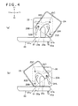
- FIG. 4 is a figure for explaining motions of a main body 20 relative to the support 30 possessed by the camera 10.
- FIG. 5 is a sectional view taken along line V-V in FIG. 2(c) .
- Y1 and Y2 shown in FIG. 1 are a forward direction (front side) and a rearward direction (rear side), respectively.
- X1 and X2 are a rightward direction (right side) and a leftward direction (left side), respectively.
- Z1 and Z2 are an upward direction (upper side) and a downward direction (lower side), respectively.
- the camera assembly 1 has a stand member 80 for supporting the camera 10 on an upper edge of a display device (a TV set or a display of a personal computer).
- the stand member 80 is mounted to an upper edge of the display device, and the camera 10 is mounted to a top surface of the stand member 80.
- the camera 10 has the main body 20 accommodating a light receiving part 21.
- the light receiving part 21 includes a lens module or a light receiving element.
- the camera 10 is connected through a cable 40 (see FIG. 1 ) to an information processing device such as a game device or a personal computer, and transmits image data acquired through the light receiving part 21 to the information processing device.
- the main body 20 has two light receiving parts 21 which are located to be spaced from each other along a left-right direction. In the information processing device, therefore, a three-dimensional image can be produced based on the image data acquired by the two light receiving parts 21.
- the number of the light receiving part or parts 21 is not limited to two, and may be one.
- the main body 20 has a microphone or microphones 22.
- the camera 10 transmits sound data acquired through the microphone or microphones 22 to the information processing device through the cable 40.
- the main body 20 in this example has a plurality of microphones 22 disposed at an interval or intervals along the left-right direction. In the information processing device, therefore, a position of a sound source can be calculated based on the sound data acquired through the plurality of microphones 22.
- the plurality of microphones 22 are aligned in the left-right direction, together with the two light receiving parts 21.
- the main body 20 has four microphones 22. Two microphones 22 are disposed between the two light receiving parts 21. This enables effective utilization of a space between the two light receiving parts 21.
- two microphones 22 are disposed on the outside of the two light receiving parts 21. Specifically, the microphones 22 are disposed respectively on the right side of the right-hand light receiving part 21 and on the left side of the left-hand light receiving part 21. This secures a long distance between the two microphones 22 disposed on the outside of the two light receiving parts 21, so that accuracy in calculation of the position of the sound source can be enhanced.
- the layout of the microphones 22 is not limited to the above-described one.
- the four microphones 4 may all be disposed on the outside of the two light receiving parts 21.
- a configuration may be adopted wherein the main body 20 has three microphones 22, and one of the microphones 22 is disposed between the two light receiving parts 21.
- the main body 20 may have only two microphones 22.
- the microphones 22 may be disposed only on the outside of the two light receiving parts 21.
- the microphones 22 may be disposed only between the two light receiving parts 21.
- the camera 10 has the support 30 aligned with the main body 20 in the left-right direction.
- the support 30 is disposed on the right side of the main body 20.
- the support 30 is located at an end portion (in this example, a right end portion) of the camera 10.
- the main body 20 is supported by the support 30 so that the orientation (the direction of an optical axis) of the light receiving parts 21 can be controlled in a vertical direction.
- the main body 20 has a flat bottom surface 20a.
- a bottom surface 30a of the support 30 can be attached to and detached from the stand member 80.
- the bottom surface 30a of the support 30 is located on a common plane on which the bottom surface 20a of the main body 20 is also located.
- This structure of the camera 10 ensures that the position of the main body 20 can be set low, and it is easy to secure stability of mounting of the camera 10.
- a support structure for supporting the main body 20 by the support 30 and a mounting structure for mounting the support 30 onto the stand member 80 will be described in detail later.
- the support 30 and the main body 20 are so formed that they are the same in sectional profile.
- the section here is a section that is orthogonal to the left-right direction.
- the main body 20 and the support 30 are substantially in the shape of a rectangular parallelepiped elongated in the left-right direction, as a whole.
- the sectional profile of the support 30 and the sectional profile of the main body 20 are both rectangles.
- the main body 20 and the support 30 set in this way, it is easy to house the camera 10 or pack the camera 10, for example, when the camera 10 is not in use.
- the above-mentioned two light receiving parts 21 and microphones 22 are aligned on a plane perpendicular to the bottom surface 20a of the main body 20.
- the main body 20 includes a circuit board (not shown) disposed in parallel to a front surface and a rear surface of the main body 20 and perpendicularly to the bottom surface 20a of the main body 20.
- the light receiving parts 21 and the microphones 22 are mounted on the circuit board. Since the main body 20 is substantially in the shape of a rectangular parallelepiped, component parts and the circuit board can be laid out therein easily.
- the shapes of the support 30 and the main body 20 are not limited to the above-described ones. For instance, the support 30 and the main body 20 may be so shaped that they are roughly semicircular in sectional profile.
- the main body 20 in this example has a case 23 and a side plate 24.
- the case 23 constitutes a front surface, a top surface, a rear surface, and a bottom surface of the main body 20, whereas the side plate 24 constitutes a side surface of the main body 20 that opposes the support 30 in the left-right direction.
- the above-mentioned light receiving parts 21 and microphones 22 are housed in a housing that includes the case 23 and the side plate 24.
- the front surface of the case 23 is formed therein with sound passing holes 23b permitting passage of sounds therethrough toward the microphones 22 (see FIG. 1 ).
- the case 23 is provided at its front surface with front panels 23a which are located in positions corresponding to the light receiving parts 21 and which are formed of a light-transmitting material.
- the case 23 is formed with a plurality of grooves 23c aligned at regular intervals along the left-right direction.
- the microphones 22 and the light receiving parts 21 are each disposed in a space between two adjacent grooves 23c.
- the support 30 in this example has a width approximately equal to the interval between the two adjacent grooves 23c. This makes it possible to restrain the support 30 from becoming conspicuous, and thereby to enhance an appearance quality of the camera 10.
- the support 30 supports the main body 20 in such a manner that the orientation of the light receiving parts 21 can be controlled in a vertical direction.
- the main body 20 is linked to the support 30 in such a manner that a tilt angle of the main body 20 can be controlled.
- the main body 20 is so supported that its bottom surface 20a is raised when the main body 20 is moved from its neutral position so as to cause a change in the orientation of the light receiving parts 21. Therefore, when the main body 20 is moved from its neutral position in the condition where the camera 10 is mounted on the stand member 80, its bottom surface 20a is separated from the top surface of the stand member 80. This structure ensures that the clearance between the main body 20 in its neutral position and the stand member 80 can be reduced.
- the "neutral position” refers to the position of the main body 20 in the condition where the bottom surface 20a of the main body 20 and the bottom surface 30a of the support 30 are on the same plane as shown in FIG. 2(a) .
- the main body 20 is in its neutral position, its bottom surface 20a is parallel to the top surface of the stand member 80.
- a front hinge shaft 25A and a rear hinge shaft 25B are provided at the side plate 24 of the main body 20.
- the support 30 and the main body 20 are linked to each other in the left-right direction by the hinge shafts 25A and 25B.
- the hinge shafts 25A and 25B are inserted into holes formed in the side plate 24, from the inner side of the side plate 24, to protrude toward the outer side of the side plate 24.
- the support 30 has a guide plate 32 opposing the side plate 24.
- the guide plate 32 is formed therein with a front guide hole 32A and a rear guide hole 32B in which the front hinge shaft 25A and the rear hinge shaft 25B are fitted, respectively.
- the front hinge shaft 25A is provided in a position deviated forward and downward from a center line C of the main body 20 that extends along the left-right direction.
- the rear hinge shaft 25B is provided in a position deviated rearward and downward from the center line C.
- the two hinge shafts 25A and 25B are provided at a lower-side portion of the side plate 24, and are located to be spaced from each other in the front-rear direction.
- the front hinge shaft 25A and the rear hinge shaft 25B are provided respectively at corner portions of the lower-side portion of the side plate 24.
- the front hinge shaft 25A is provided in a front-side corner, while the rear hinge shaft 25B is provided in a rear-side corner.
- FIG. 4 is a figure for explaining motions of the main body 20 relative to the support 30.
- the side plate 24 and the guide plate 32 of the support 30 are illustrated.
- the main body 20 is rotated about the front hinge shaft 25A when tilted forward from its neutral position so that the orientation of the light receiving parts 21 becomes obliquely downward.
- the bottom surface 20a of the main body 20 is raised.
- the front hinge shaft 25A is supported at a lower end of the front guide hole 32A.
- FIG. 4 is a figure for explaining motions of the main body 20 relative to the support 30.
- the side plate 24 and the guide plate 32 of the support 30 are illustrated.
- the main body 20 is rotated about the front hinge shaft 25A when tilted forward from its neutral position so that the orientation of the light receiving parts 21 becomes obliquely downward.
- the bottom surface 20a of the main body 20 is raised.
- the front hinge shaft 25A is supported at a lower end of the front guide hole 32A.
- the main body 20 is rotated about the rear hinge shaft 25B when tilted rearward so that the orientation of the light receiving parts 21 becomes obliquely downward. As a result, in this case also, the bottom surface 20a of the main body 20 is raised.
- the rear hinge shaft 25B is supported at a lower end of the rear guide hole 32B.
- the front guide hole 32A is so formed as to permit a motion of the front hinge shaft 25A when the main body 20 is tilted rearward from its neutral position.
- the front guide hole 32A is formed in the shape of an arc of a circle with a center on the rear hinge shaft 25B, in conformity with an orbital path of the front hinge shaft 25A in this instance.
- the rear guide hole 32B is so formed as to permit a motion of the rear hinge shaft 25B when the main body 20 is tilted forward from its neutral position, as shown in FIG. 4(a) .
- the rear guide hole 32B is formed in the shape of an arc of a circle with a center on the front hinge shaft 25A, in conformity with an orbital path of the rear hinge shaft 25B in this instance.
- the front hinge shaft 25A and the rear hinge shaft 25B are located at the lower end of the front guide hole 32A and the lower end of the rear guide hole 32B, respectively.
- An upper end of the front guide hole 32A and an upper end of the rear guide hole 32B function as stoppers for determining tilt angle upper limits for the main body 20.
- the orientation of the light receiving parts 21 can be tilted upward until the front hinge shaft 25A abuts on the upper end of the front guide hole 32A, as shown in FIG. 4(b) .
- the orientation of the light receiving parts 21 can be tilted downward until the rear hinge shaft 25B abuts on the upper end of the rear guide hole 32B, as shown in FIG. 4(a) .
- the shapes of the guide holes 32A and 32B are not necessarily be limited to the arcuate shapes, insofar as the guide holes 32A and 32B have lower ends for supporting the hinge shafts 25A and 25B and upper ends for restricting the motions of the hinge shafts 25A and 25B and their shapes permit movements of the hinge shafts 25A and 25B.
- the guide plate 32 may be formed with a single large hole ranging from the front guide hole 32A to the rear guide hole 32B.
- an inner peripheral surface of the front guide hole 32A includes a surface located inwardly of the orbital path of the front hinge shaft 25A and a surface located outwardly of the orbital path of the front hinge shaft 25A.
- either one may not necessarily be along the orbital path of the front hinge shaft 25A.
- the guide plate 32 may not necessarily be formed with a surface located outwardly of the orbital path of the front hinge shaft 25A.
- an inner peripheral surface of the rear guide hole 32B includes a surface located inwardly of the orbital path of the rear hinge shaft 25B and a surface located outwardly of the orbital path of the rear hinge shaft 25B.
- either one may not necessarily be along the orbital path of the rear hinge shaft 25B.
- the guide plate 32 may not necessarily be formed with a surface located outwardly of the orbital path of the rear hinge shaft 25B.
- the hinge shafts 25A and 25B in this example protrude from the inner side toward the outer side of the side plate 24, and are fitted respectively in the guide holes 32A and 32B of the guide plate 32.
- slip-off preventive members e.g., E-rings
- E-rings slip-off preventive members
- washers 4 and elastic members (in this example, spring washers) 5 for pressing the washers 4 against edges of the guide holes 32A and 32B, respectively. This results in generation of frictional forces between the washers 4 and the edges of the guide holes 32A and 32B. Owing to these frictional forces, the main body 20 can be held at an arbitrary tilt angle.
- a guided shaft 25C is provided at the side plate 24, in addition to the hinge shafts 25A and 25B.
- the guided shaft 25C is inserted into a hole formed in the side plate 24, from the inner side of the side plate 24, to protrude toward the outer side of the side plate 24.
- the guided shaft 25C is provided at an upper-side portion of the side plate 24, contrary to the hinge shafts 25A and 25B.
- the guided shaft 25C is located at a position equidistant from the front hinge shaft 25A and from the rear hinge shaft 25B.
- the guide plate 32 is formed with a guide hole 32C in which the guided shaft 25C is to be fitted.
- the guide hole 32C is formed in conformity with an orbital path of the guided shaft 25C at the time of rotation of the main body 20. Specifically, in conformity with an orbital path of the guided shaft 25C at the time of forward tilting of the main body 20 as shown in FIG. 4(a) and an orbital path of the guided shaft 25C at the time of rearward tilting of the main body 20 as shown in FIG. 4(b) , the guide hole 32C has a shape obtained by joining together an arc of a circle with a center on the front hinge shaft 25A and an arc of a circle with a center on the rear hinge shaft 25B.
- the guided shaft 25C and the guide hole 32C it is possible to restrain a gap from being generated between the side plate 24 and the guide plate 32.
- the guided shaft 25C is located in the center of the guide hole 32C, namely, in a joining position where the arc of the circle with the center on the front hinge shaft 25A and the arc of the circle with the center on the rear hinge shaft 25B join.
- a slip-off preventive member e.g., E-ring
- E-ring a slip-off preventive member 3 for preventing this shaft from slipping off from the guide hole 32C, like in the case of the hinge shafts 25A and 25B.
- a washer 4 and an elastic member 5 for pressing the washer 4 to an end of the guide hole 32C.
- the direction of insertion of the hinge shafts 25A and 25B and the guided shaft 25C may be opposite to the aforementioned direction.
- the hinge shafts 25A and 25B and the guided shaft 25C may be passed through the guide holes 32A, 32B, and 32C from the inside of the support 30, to protrude to the outside of the support 30, and be fixed into holes in the side plate 24.
- the support 30 in addition to the guide plate 32, the support 30 also has a case 34 constituting an outside surface of the support 30, and a frame 35 which is disposed inside the case 34 and to which the guide plate 32 is mounted.
- the guide plate 32 and the frame 35 are fixed to each other by a plurality of screws 6.
- the above-mentioned slip-off preventive members 3, washers 4, and elastic members 5 are disposed between the guide plate 32 and the frame 35.
- the bottom surface 30a of the support 30 is attachable to and detachable from the stand member 80.
- one of the bottom surface 30a of the support 30 and the top surface of the stand member 80 is provided with an engaging part projecting toward the other.
- the other is provided with an engaged part composed of a hole or recess in which the engaging part is fitted. The engaging part is held in the state of being fitted in the engaged part.
- the stand member 80 is provided with an engaging shaft 85, as the above-mentioned engaging part.
- the support 30 has a bottom plate 36 at a bottom portion thereof.
- the bottom plate 36 is formed with an engaged hole 36a, as the above-mentioned engaged part, and the engaging shaft 85 is fitted in the engaged hole 36a.
- the support 30 has a roughly U-shaped holding pin 37 on the bottom plate 36 (on the inner side of the bottom plate 36).
- the engaging shaft 85 is formed with a groove in an outer peripheral surface thereof, and the holding pin 37 elastically holds the grooved portion. In the condition where the engaging shaft 85 is held by the holding pin 37, the bottom surface 30a of the support 30 is in contact with the top surface of the stand member 80. With the holding pin 37 elastically deformed to expand (open wider), the engaging shaft 85 can be fitted into the inside of the holding pin 37 or be disengaged from the holding pin 37.
- the support 30 has a holding plate 39 for fixing the holding pin 37 to the bottom plate 36.
- the stand member 80 is provided with a plurality of (in the example described here, four) positioning projections 84a. These positioning projections 84a are so arranged as to surround the engaging shaft 85.
- the bottom plate 36 of the support 30 is formed with a recess 36b in which the positioning projections 84a are to be fitted.
- the recess 36b described here is a rectangular groove (see FIG. 2(c) ) joining positions which correspond respectively to the four positioning projections 84a.
- the positioning projections 84a are located at corner portions of the recess 36b. This ensures that clockwise or counterclockwise rotation of the camera 10 relative to the stand member 80 and movements of the camera 10 in the front-rear direction relative to the stand member 80 are restrained by the positioning projections 84a and the recess 36b.
- the bottom plate 36 is mounted to a bottom surface of the frame 35.
- a plurality of (in this example, two) screws 7 are inserted into the bottom plate 36 from below.
- the screws 7 protrude upward beyond a lower wall portion 35a of the frame 35.
- the case 34 and the frame 35 are fitted to each other in the left-right direction.
- the case 34 has a mounting portion 34a located on the lower wall portion 35a. The screws 7 are engaged into threaded holes formed in the mounting portion 34a. This ensures that the frame 35, the bottom plate 36, and the case 34 are fixed to one another by the screws 7.
- the camera 10 has the cable 40.
- the cable 40 has a connector 41 at one end thereof.
- the connector 41 is housed in the main body 20, and is connected to a connector provided on the circuit board inside the main body 20.
- the side plate 24, the guide plate 32, and the frame 35 are formed respectively with holes 24e, 32e, and 35e piercing them in the left-right direction.
- the cable 40 extends from the connector 41 toward the outer side (in this example, the right side) in the left-right direction while passing through the holes 24e, 32e, and 35e. Thereafter, the cable 40 extends rearward from the support 30.
- the cable 40 is provided with a bush 42 at a position spaced from the connector 41.
- the bush 42 includes a plate-shaped front portion 42a disposed inside the frame 35, and a rear portion 42b (see FIG. 2(b) ) which is located on the rear side of the support 30 and which contacts the rear surface of the support 30.
- a bottom surface 42c of the rear portion 42b is located on the common plane on which the bottom surface 30a of the support 30 and the bottom surface 20a of the main body 20 are also located. Therefore, stability of mounting of the camera 10 can be further enhanced.
- a rear wall portion of the frame 35 is formed with a groove 35b. A portion between the front portion 42a and the rear portion 42b is held inside the groove 35b.
- the stand member 80 will be described. As shown in FIG. 1 , the stand member 80 has a support plate 81 on which to mount the camera 10.
- the support plate 81 is disposed at an upper edge of a display device.
- a front edge 81b of the support plate 81 is located rearwardly of the front surface of the camera 10 (see FIG. 4 ). This securely restrains the main body 20 of the camera 10 and the support plate 81 from interfering with each other when the main body 20 is tilted forward.
- a rear edge 81c of the support plate 81 is located forwardly of the rear surface of the camera 10.
- the support plate 81 has a flat top surface.
- a width in the left-right direction of the support plate 81 in this example is corresponding to a width of the camera 10 in the left-right direction. More in detail, the support plate 81 has the width equal to the width of the camera 10 in the left-right direction. Accordingly, the top surface of the support plate 81 has a portion to which to mount the bottom surface 30a of the support 30 of the camera 10, and a portion on which to mount the main body 20 of the camera 10.
- Such a shape of the support plate 81 ensures that the camera 10 can be supported in a stable manner.
- the support plate 81 in this example includes an upper case 81e constituting an upper-side portion thereof and a lower case 81f constituting a lower-side portion thereof.
- a plate 84, which has the positioning projections 84a, and the engaging shaft 85 are disposed between these two cases 81e and 81f.
- the positioning projections 84a and the engaging shaft 85 protrude upward via holes formed in the upper case 81e.
- the support plate 81 has at a central portion thereof an extension part 81d extending rearward.
- the stand member 80 has a first movable plate 82 linked to a rear edge of the extension part 81d, and a second movable plate 83 linked to a rear edge of the first movable plate 82.
- the extension part 81d and the first movable plate 82 are linked to each other by a hinge 86.
- the first movable plate 82 and the second movable plate 83 are linked to each other by a hinge 87.
- the support plate 81 is formed at its front edge with a hook 81a projecting downward.
- the hook 81a is caught on the front side of the upper edge of a display device.
- the first movable plate 82 and the second movable plate 83 can as a whole be bent downward, as shown in FIG. 1 .
- a rear edge (lower edge) of the second movable plate 83 makes contact with a rear surface of the display device.
- the stand member 80 is mounted to the display device in a state in which the display device is clamped between the hook 81a and the rear edge of the second movable plate 83.
- an anti-slip member 83a formed of rubber or the like may be provided at the rear edge of the second movable plate 83.
- the camera 10 may include two main bodies 20 in which two light receiving parts 21 are housed respectively.
- a support 30 may be disposed between the two main bodies 20.
- the camera 10 may have only one hinge shaft.
- the side plate 24 and the guide plate 32 may support the hinge shaft in such a manner that the hinge shaft can be vertically moved when the main body 20 is moved to cause the orientation of the light receiving parts 21 to be changed in a vertical direction. This eliminates the need to secure, between the main body 20 in its neutral position and the stand member 80, a clearance for allowing for rotation of the main body 20. As a result, stability of mounting the main body 20 can be enhanced.
- the guided shaft 25C and the guide hole 32C corresponding thereto may not necessarily be provided.
Landscapes
- Engineering & Computer Science (AREA)
- Physics & Mathematics (AREA)
- General Physics & Mathematics (AREA)
- General Engineering & Computer Science (AREA)
- Multimedia (AREA)
- Signal Processing (AREA)
- Mechanical Engineering (AREA)
- Accessories Of Cameras (AREA)
- Studio Devices (AREA)
- Cameras In General (AREA)
Abstract
Description
- The present invention relates to a camera that is mounted to an edge of a display device.
- Heretofore, there has been utilized a camera which is mounted to an edge of a display device (for example, a TV set or a display of a personal computer) and in which an orientation of a light receiving part can be controlled in a vertical direction. A camera that is disclosed in
Japanese Design Registration No. 1291736 - In the structure wherein the mounting part is provided at a position spaced downward from the main body as in the above-mentioned
Patent Document 1, the position of the main body of the camera becomes high when the camera is used, which makes it difficult to secure stability of mounting. - A camera for solving the above-mentioned problem includes: a main body accommodating a light receiving part, the main body having a flat bottom surface; and a support which is aligned with the main body in a left-right direction, supports the main body so as to permit orientation of the light receiving part to be controlled in a vertical direction, and has a bottom surface located on a common plane whereon the bottom surface of the main body is also located, the bottom surface of the support being attachable to and detachable from a stand member mounted to a display device.
- A camera assembly for solving the above-mentioned problem includes a camera and a stand member for mounting to a display device, wherein the camera includes: a main body accommodating a light receiving part, the main body having a flat bottom surface; and a support which is aligned with the main body in a left-right direction, supports the main body so as to permit orientation of the light receiving part to be controlled in a vertical direction, and has a bottom surface located on a common plane whereon the bottom surface of the main body is also located, the bottom surface of the support being attachable to and detachable from the stand member.
- According to the camera and the camera assembly as above-mentioned, stability of mounting of the camera can be enhanced.
-
- [
FIG. 1 ]
FIG. 1 is an exploded perspective view of a camera assembly according to one embodiment of the present invention. - [
FIG. 2 ]
FIG. 2 illustrates a camera constituting the camera assembly, wherein (a) of the figure is a front view, (b) is a side view, and (c) is a lower view. - [
FIG. 3 ]
FIG. 3 is an exploded perspective view of a support possessed by the camera. - [
FIG. 4 ]
FIG. 4 is a figure for explaining motions of a main body relative to the support possessed by the camera. - [
FIG. 5 ]
FIG. 5 is a sectional view taken along line V-V inFIG. 2(c) . - Now, one embodiment of the present invention will be described below, referring to the drawings.
FIG. 1 is an exploded perspective view of acamera assembly 1 according to one embodiment of the present invention.FIG. 2 illustrates acamera 10 constituting thecamera assembly 1, wherein (a) of the figure is a front view, (b) is a side view, and (c) is a lower view.FIG. 3 is an exploded perspective view of asupport 30 possessed by thecamera 10.FIG. 4 is a figure for explaining motions of amain body 20 relative to thesupport 30 possessed by thecamera 10.FIG. 5 is a sectional view taken along line V-V inFIG. 2(c) . - In the following description, Y1 and Y2 shown in
FIG. 1 are a forward direction (front side) and a rearward direction (rear side), respectively. In addition, X1 and X2 are a rightward direction (right side) and a leftward direction (left side), respectively. Besides, Z1 and Z2 are an upward direction (upper side) and a downward direction (lower side), respectively. - As shown in
FIG. 1 , thecamera assembly 1 has astand member 80 for supporting thecamera 10 on an upper edge of a display device (a TV set or a display of a personal computer). Thestand member 80 is mounted to an upper edge of the display device, and thecamera 10 is mounted to a top surface of thestand member 80. - As shown in
FIG. 2(a) , thecamera 10 has themain body 20 accommodating alight receiving part 21. Thelight receiving part 21 includes a lens module or a light receiving element. Thecamera 10 is connected through a cable 40 (seeFIG. 1 ) to an information processing device such as a game device or a personal computer, and transmits image data acquired through thelight receiving part 21 to the information processing device. In this example, themain body 20 has twolight receiving parts 21 which are located to be spaced from each other along a left-right direction. In the information processing device, therefore, a three-dimensional image can be produced based on the image data acquired by the twolight receiving parts 21. The number of the light receiving part orparts 21 is not limited to two, and may be one. - As shown in
FIG. 2(a) , themain body 20 has a microphone ormicrophones 22. Thecamera 10 transmits sound data acquired through the microphone ormicrophones 22 to the information processing device through thecable 40. Themain body 20 in this example has a plurality ofmicrophones 22 disposed at an interval or intervals along the left-right direction. In the information processing device, therefore, a position of a sound source can be calculated based on the sound data acquired through the plurality ofmicrophones 22. The plurality ofmicrophones 22 are aligned in the left-right direction, together with the twolight receiving parts 21. In this example, themain body 20 has fourmicrophones 22. Twomicrophones 22 are disposed between the two light receivingparts 21. This enables effective utilization of a space between the two light receivingparts 21. In addition, twomicrophones 22 are disposed on the outside of the two light receivingparts 21. Specifically, themicrophones 22 are disposed respectively on the right side of the right-handlight receiving part 21 and on the left side of the left-handlight receiving part 21. This secures a long distance between the twomicrophones 22 disposed on the outside of the twolight receiving parts 21, so that accuracy in calculation of the position of the sound source can be enhanced. - The layout of the
microphones 22 is not limited to the above-described one. For example, the four microphones 4 may all be disposed on the outside of the twolight receiving parts 21. In addition, a configuration may be adopted wherein themain body 20 has threemicrophones 22, and one of themicrophones 22 is disposed between the two light receivingparts 21. Furthermore, themain body 20 may have only twomicrophones 22. In this case, themicrophones 22 may be disposed only on the outside of the twolight receiving parts 21. Besides, themicrophones 22 may be disposed only between the two light receivingparts 21. - As shown in
FIG. 2(a) , thecamera 10 has thesupport 30 aligned with themain body 20 in the left-right direction. In this example, thesupport 30 is disposed on the right side of themain body 20. In other words, thesupport 30 is located at an end portion (in this example, a right end portion) of thecamera 10. Themain body 20 is supported by thesupport 30 so that the orientation (the direction of an optical axis) of thelight receiving parts 21 can be controlled in a vertical direction. Themain body 20 has aflat bottom surface 20a. Abottom surface 30a of thesupport 30 can be attached to and detached from thestand member 80. Thebottom surface 30a of thesupport 30 is located on a common plane on which thebottom surface 20a of themain body 20 is also located. This structure of thecamera 10 ensures that the position of themain body 20 can be set low, and it is easy to secure stability of mounting of thecamera 10. A support structure for supporting themain body 20 by thesupport 30 and a mounting structure for mounting thesupport 30 onto thestand member 80 will be described in detail later. - The
support 30 and themain body 20 are so formed that they are the same in sectional profile. The section here is a section that is orthogonal to the left-right direction. In this example, themain body 20 and thesupport 30 are substantially in the shape of a rectangular parallelepiped elongated in the left-right direction, as a whole. Of a right-hand portion and a left-hand portion of the rectangular parallelepiped, one (in this example, the left-hand portion) is themain body 20, and the other (in this example, the right-hand portion) is thesupport 30. Therefore, the sectional profile of thesupport 30 and the sectional profile of themain body 20 are both rectangles. With the shapes of themain body 20 and thesupport 30 set in this way, it is easy to house thecamera 10 or pack thecamera 10, for example, when thecamera 10 is not in use. The above-mentioned two light receivingparts 21 andmicrophones 22 are aligned on a plane perpendicular to thebottom surface 20a of themain body 20. More in detail, themain body 20 includes a circuit board (not shown) disposed in parallel to a front surface and a rear surface of themain body 20 and perpendicularly to thebottom surface 20a of themain body 20. Thelight receiving parts 21 and themicrophones 22 are mounted on the circuit board. Since themain body 20 is substantially in the shape of a rectangular parallelepiped, component parts and the circuit board can be laid out therein easily. It is to be noted that the shapes of thesupport 30 and themain body 20 are not limited to the above-described ones. For instance, thesupport 30 and themain body 20 may be so shaped that they are roughly semicircular in sectional profile. - As shown in
FIG. 3 , themain body 20 in this example has acase 23 and aside plate 24. Thecase 23 constitutes a front surface, a top surface, a rear surface, and a bottom surface of themain body 20, whereas theside plate 24 constitutes a side surface of themain body 20 that opposes thesupport 30 in the left-right direction. The above-mentionedlight receiving parts 21 andmicrophones 22 are housed in a housing that includes thecase 23 and theside plate 24. The front surface of thecase 23 is formed therein with sound passing holes 23b permitting passage of sounds therethrough toward the microphones 22 (seeFIG. 1 ). In addition, thecase 23 is provided at its front surface withfront panels 23a which are located in positions corresponding to thelight receiving parts 21 and which are formed of a light-transmitting material. - As shown in
FIG. 1 , thecase 23 is formed with a plurality ofgrooves 23c aligned at regular intervals along the left-right direction. Themicrophones 22 and thelight receiving parts 21 are each disposed in a space between twoadjacent grooves 23c. Thesupport 30 in this example has a width approximately equal to the interval between the twoadjacent grooves 23c. This makes it possible to restrain thesupport 30 from becoming conspicuous, and thereby to enhance an appearance quality of thecamera 10. - As aforementioned, the
support 30 supports themain body 20 in such a manner that the orientation of thelight receiving parts 21 can be controlled in a vertical direction. In other words, themain body 20 is linked to thesupport 30 in such a manner that a tilt angle of themain body 20 can be controlled. In this example, themain body 20 is so supported that itsbottom surface 20a is raised when themain body 20 is moved from its neutral position so as to cause a change in the orientation of thelight receiving parts 21. Therefore, when themain body 20 is moved from its neutral position in the condition where thecamera 10 is mounted on thestand member 80, itsbottom surface 20a is separated from the top surface of thestand member 80. This structure ensures that the clearance between themain body 20 in its neutral position and thestand member 80 can be reduced. As a result, it becomes easier to secure stability of mounting of thecamera 10. It is to be noted that the "neutral position" refers to the position of themain body 20 in the condition where thebottom surface 20a of themain body 20 and thebottom surface 30a of thesupport 30 are on the same plane as shown inFIG. 2(a) . When themain body 20 is in its neutral position, itsbottom surface 20a is parallel to the top surface of thestand member 80. - The support structure for supporting the
main body 20 by thesupport 30 will be described in detail. As shown inFIG. 3 , afront hinge shaft 25A and arear hinge shaft 25B are provided at theside plate 24 of themain body 20. Thesupport 30 and themain body 20 are linked to each other in the left-right direction by thehinge shafts hinge shafts side plate 24, from the inner side of theside plate 24, to protrude toward the outer side of theside plate 24. Thesupport 30 has aguide plate 32 opposing theside plate 24. Theguide plate 32 is formed therein with afront guide hole 32A and arear guide hole 32B in which thefront hinge shaft 25A and therear hinge shaft 25B are fitted, respectively. - The
front hinge shaft 25A is provided in a position deviated forward and downward from a center line C of themain body 20 that extends along the left-right direction. Therear hinge shaft 25B is provided in a position deviated rearward and downward from the center line C. In other words, the twohinge shafts side plate 24, and are located to be spaced from each other in the front-rear direction. In this example, thefront hinge shaft 25A and therear hinge shaft 25B are provided respectively at corner portions of the lower-side portion of theside plate 24. Thefront hinge shaft 25A is provided in a front-side corner, while therear hinge shaft 25B is provided in a rear-side corner. -
FIG. 4 is a figure for explaining motions of themain body 20 relative to thesupport 30. In this figure, theside plate 24 and theguide plate 32 of thesupport 30 are illustrated. As shown inFIG. 4(a) , themain body 20 is rotated about thefront hinge shaft 25A when tilted forward from its neutral position so that the orientation of thelight receiving parts 21 becomes obliquely downward. As a result, thebottom surface 20a of themain body 20 is raised. When themain body 20 is thus tilted forward, thefront hinge shaft 25A is supported at a lower end of thefront guide hole 32A. As shown inFIG. 4(b) , themain body 20 is rotated about therear hinge shaft 25B when tilted rearward so that the orientation of thelight receiving parts 21 becomes obliquely downward. As a result, in this case also, thebottom surface 20a of themain body 20 is raised. When themain body 20 is tilted rearward from its neutral position, therear hinge shaft 25B is supported at a lower end of therear guide hole 32B. - As shown in
FIG. 4(b) , thefront guide hole 32A is so formed as to permit a motion of thefront hinge shaft 25A when themain body 20 is tilted rearward from its neutral position. To be more specific, thefront guide hole 32A is formed in the shape of an arc of a circle with a center on therear hinge shaft 25B, in conformity with an orbital path of thefront hinge shaft 25A in this instance. On the other hand, therear guide hole 32B is so formed as to permit a motion of therear hinge shaft 25B when themain body 20 is tilted forward from its neutral position, as shown inFIG. 4(a) . To be more specific, therear guide hole 32B is formed in the shape of an arc of a circle with a center on thefront hinge shaft 25A, in conformity with an orbital path of therear hinge shaft 25B in this instance. When themain body 20 is in its neutral position, thefront hinge shaft 25A and therear hinge shaft 25B are located at the lower end of thefront guide hole 32A and the lower end of therear guide hole 32B, respectively. - An upper end of the
front guide hole 32A and an upper end of therear guide hole 32B function as stoppers for determining tilt angle upper limits for themain body 20. Specifically, the orientation of thelight receiving parts 21 can be tilted upward until thefront hinge shaft 25A abuts on the upper end of thefront guide hole 32A, as shown inFIG. 4(b) . In addition, the orientation of thelight receiving parts 21 can be tilted downward until therear hinge shaft 25B abuts on the upper end of therear guide hole 32B, as shown inFIG. 4(a) . - The shapes of the guide holes 32A and 32B are not necessarily be limited to the arcuate shapes, insofar as the guide holes 32A and 32B have lower ends for supporting the
hinge shafts hinge shafts hinge shafts guide plate 32 may be formed with a single large hole ranging from thefront guide hole 32A to therear guide hole 32B. In addition, an inner peripheral surface of thefront guide hole 32A includes a surface located inwardly of the orbital path of thefront hinge shaft 25A and a surface located outwardly of the orbital path of thefront hinge shaft 25A. However, of these two surfaces, either one (for example, the surface located outwardly of the orbital path) may not necessarily be along the orbital path of thefront hinge shaft 25A. Besides, theguide plate 32 may not necessarily be formed with a surface located outwardly of the orbital path of thefront hinge shaft 25A. Similarly, an inner peripheral surface of therear guide hole 32B includes a surface located inwardly of the orbital path of therear hinge shaft 25B and a surface located outwardly of the orbital path of therear hinge shaft 25B. However, of these two surfaces, either one (for example, the surface located outwardly of the orbital path) may not necessarily be along the orbital path of therear hinge shaft 25B. In addition, theguide plate 32 may not necessarily be formed with a surface located outwardly of the orbital path of therear hinge shaft 25B. - As above-mentioned, the
hinge shafts side plate 24, and are fitted respectively in the guide holes 32A and 32B of theguide plate 32. To end portions of thehinge shafts hinge shafts main body 20 can be held at an arbitrary tilt angle. - As shown in
FIG. 3 , a guidedshaft 25C is provided at theside plate 24, in addition to thehinge shafts hinge shafts shaft 25C is inserted into a hole formed in theside plate 24, from the inner side of theside plate 24, to protrude toward the outer side of theside plate 24. The guidedshaft 25C is provided at an upper-side portion of theside plate 24, contrary to thehinge shafts shaft 25C is located at a position equidistant from thefront hinge shaft 25A and from therear hinge shaft 25B. Theguide plate 32 is formed with aguide hole 32C in which the guidedshaft 25C is to be fitted. Theguide hole 32C is formed in conformity with an orbital path of the guidedshaft 25C at the time of rotation of themain body 20. Specifically, in conformity with an orbital path of the guidedshaft 25C at the time of forward tilting of themain body 20 as shown inFIG. 4(a) and an orbital path of the guidedshaft 25C at the time of rearward tilting of themain body 20 as shown inFIG. 4(b) , theguide hole 32C has a shape obtained by joining together an arc of a circle with a center on thefront hinge shaft 25A and an arc of a circle with a center on therear hinge shaft 25B. Owing to the guidedshaft 25C and theguide hole 32C, it is possible to restrain a gap from being generated between theside plate 24 and theguide plate 32. When themain body 20 is in its neutral position, the guidedshaft 25C is located in the center of theguide hole 32C, namely, in a joining position where the arc of the circle with the center on thefront hinge shaft 25A and the arc of the circle with the center on therear hinge shaft 25B join. - It is to be noted that to an end portion of the guided
shaft 25C is attached a slip-off preventive member (e.g., E-ring) 3 for preventing this shaft from slipping off from theguide hole 32C, like in the case of thehinge shafts shaft 25C are mounted a washer 4 and anelastic member 5 for pressing the washer 4 to an end of theguide hole 32C. - It is to be noted that the direction of insertion of the
hinge shafts shaft 25C may be opposite to the aforementioned direction. In other words, thehinge shafts shaft 25C may be passed through the guide holes 32A, 32B, and 32C from the inside of thesupport 30, to protrude to the outside of thesupport 30, and be fixed into holes in theside plate 24. - As shown in
FIG. 3 , in addition to theguide plate 32, thesupport 30 also has acase 34 constituting an outside surface of thesupport 30, and aframe 35 which is disposed inside thecase 34 and to which theguide plate 32 is mounted. Theguide plate 32 and theframe 35 are fixed to each other by a plurality ofscrews 6. The above-mentioned slip-offpreventive members 3, washers 4, andelastic members 5 are disposed between theguide plate 32 and theframe 35. - As aforementioned, the
bottom surface 30a of thesupport 30 is attachable to and detachable from thestand member 80. Specifically, one of thebottom surface 30a of thesupport 30 and the top surface of thestand member 80 is provided with an engaging part projecting toward the other. In addition, the other is provided with an engaged part composed of a hole or recess in which the engaging part is fitted. The engaging part is held in the state of being fitted in the engaged part. - In the example shown in
FIGS. 1 and5 , thestand member 80 is provided with an engagingshaft 85, as the above-mentioned engaging part. Thesupport 30 has abottom plate 36 at a bottom portion thereof. Thebottom plate 36 is formed with anengaged hole 36a, as the above-mentioned engaged part, and the engagingshaft 85 is fitted in the engagedhole 36a. In addition, thesupport 30 has a roughlyU-shaped holding pin 37 on the bottom plate 36 (on the inner side of the bottom plate 36). The engagingshaft 85 is formed with a groove in an outer peripheral surface thereof, and the holdingpin 37 elastically holds the grooved portion. In the condition where the engagingshaft 85 is held by the holdingpin 37, thebottom surface 30a of thesupport 30 is in contact with the top surface of thestand member 80. With the holdingpin 37 elastically deformed to expand (open wider), the engagingshaft 85 can be fitted into the inside of the holdingpin 37 or be disengaged from the holdingpin 37. Thesupport 30 has a holdingplate 39 for fixing the holdingpin 37 to thebottom plate 36. - One of the
bottom surface 30a of thesupport 30 and the top surface of thestand member 80 is provided with a plurality of positioning projections projecting toward the other. In this example, as shown inFIGS. 1 and5 , thestand member 80 is provided with a plurality of (in the example described here, four)positioning projections 84a. Thesepositioning projections 84a are so arranged as to surround the engagingshaft 85. Thebottom plate 36 of thesupport 30 is formed with arecess 36b in which thepositioning projections 84a are to be fitted. Therecess 36b described here is a rectangular groove (seeFIG. 2(c) ) joining positions which correspond respectively to the fourpositioning projections 84a. Thepositioning projections 84a are located at corner portions of therecess 36b. This ensures that clockwise or counterclockwise rotation of thecamera 10 relative to thestand member 80 and movements of thecamera 10 in the front-rear direction relative to thestand member 80 are restrained by thepositioning projections 84a and therecess 36b. - As shown in
FIGS. 3 and5 , thebottom plate 36 is mounted to a bottom surface of theframe 35. In this example, a plurality of (in this example, two)screws 7 are inserted into thebottom plate 36 from below. Thescrews 7 protrude upward beyond alower wall portion 35a of theframe 35. Thecase 34 and theframe 35 are fitted to each other in the left-right direction. Thecase 34 has a mountingportion 34a located on thelower wall portion 35a. Thescrews 7 are engaged into threaded holes formed in the mountingportion 34a. This ensures that theframe 35, thebottom plate 36, and thecase 34 are fixed to one another by thescrews 7. - As shown in
FIG. 3 , thecamera 10 has thecable 40. Thecable 40 has aconnector 41 at one end thereof. Theconnector 41 is housed in themain body 20, and is connected to a connector provided on the circuit board inside themain body 20. Theside plate 24, theguide plate 32, and theframe 35 are formed respectively withholes cable 40 extends from theconnector 41 toward the outer side (in this example, the right side) in the left-right direction while passing through theholes cable 40 extends rearward from thesupport 30. - As shown in
FIG. 3 , thecable 40 is provided with abush 42 at a position spaced from theconnector 41. Thebush 42 includes a plate-shapedfront portion 42a disposed inside theframe 35, and arear portion 42b (seeFIG. 2(b) ) which is located on the rear side of thesupport 30 and which contacts the rear surface of thesupport 30. As shown inFIG. 2(b) , abottom surface 42c of therear portion 42b is located on the common plane on which thebottom surface 30a of thesupport 30 and thebottom surface 20a of themain body 20 are also located. Therefore, stability of mounting of thecamera 10 can be further enhanced. As shown inFIG. 3 , a rear wall portion of theframe 35 is formed with agroove 35b. A portion between thefront portion 42a and therear portion 42b is held inside thegroove 35b. - The
stand member 80 will be described. As shown inFIG. 1 , thestand member 80 has asupport plate 81 on which to mount thecamera 10. Thesupport plate 81 is disposed at an upper edge of a display device. Afront edge 81b of thesupport plate 81 is located rearwardly of the front surface of the camera 10 (seeFIG. 4 ). This securely restrains themain body 20 of thecamera 10 and thesupport plate 81 from interfering with each other when themain body 20 is tilted forward. Similarly, arear edge 81c of thesupport plate 81 is located forwardly of the rear surface of thecamera 10. - The
support plate 81 has a flat top surface. A width in the left-right direction of thesupport plate 81 in this example is corresponding to a width of thecamera 10 in the left-right direction. More in detail, thesupport plate 81 has the width equal to the width of thecamera 10 in the left-right direction. Accordingly, the top surface of thesupport plate 81 has a portion to which to mount thebottom surface 30a of thesupport 30 of thecamera 10, and a portion on which to mount themain body 20 of thecamera 10. Such a shape of thesupport plate 81 ensures that thecamera 10 can be supported in a stable manner. - In this example, at an end portion (in this example, a right end portion) of the top surface of the
support plate 81 are provided the aforementioned engagingshaft 85 andpositioning projections 84a. It is to be noted that as shown inFIG. 5 , thesupport plate 81 in this example includes anupper case 81e constituting an upper-side portion thereof and alower case 81f constituting a lower-side portion thereof. Aplate 84, which has thepositioning projections 84a, and the engagingshaft 85 are disposed between these twocases positioning projections 84a and the engagingshaft 85 protrude upward via holes formed in theupper case 81e. - As shown in
FIG. 1 , thesupport plate 81 has at a central portion thereof anextension part 81d extending rearward. Thestand member 80 has a firstmovable plate 82 linked to a rear edge of theextension part 81d, and a secondmovable plate 83 linked to a rear edge of the firstmovable plate 82. Theextension part 81d and the firstmovable plate 82 are linked to each other by ahinge 86. The firstmovable plate 82 and the secondmovable plate 83 are linked to each other by ahinge 87. - The
support plate 81 is formed at its front edge with ahook 81a projecting downward. When thestand member 80 is in use, thehook 81a is caught on the front side of the upper edge of a display device. The firstmovable plate 82 and the secondmovable plate 83 can as a whole be bent downward, as shown inFIG. 1 . A rear edge (lower edge) of the secondmovable plate 83 makes contact with a rear surface of the display device. In other words, thestand member 80 is mounted to the display device in a state in which the display device is clamped between thehook 81a and the rear edge of the secondmovable plate 83. Preferably, ananti-slip member 83a formed of rubber or the like may be provided at the rear edge of the secondmovable plate 83. - It is to be noted that the present invention is not limited to the
aforementioned camera 10 andcamera assembly 1, and various modifications are possible. - For instance, the
camera 10 may include twomain bodies 20 in which twolight receiving parts 21 are housed respectively. In this case, asupport 30 may be disposed between the twomain bodies 20. - In addition, the
camera 10 may have only one hinge shaft. In this case, theside plate 24 and theguide plate 32 may support the hinge shaft in such a manner that the hinge shaft can be vertically moved when themain body 20 is moved to cause the orientation of thelight receiving parts 21 to be changed in a vertical direction. This eliminates the need to secure, between themain body 20 in its neutral position and thestand member 80, a clearance for allowing for rotation of themain body 20. As a result, stability of mounting themain body 20 can be enhanced. - Besides, the guided
shaft 25C and theguide hole 32C corresponding thereto may not necessarily be provided.
Claims (8)
- A camera comprising:a main body accommodating a light receiving part, the main body having a flat bottom surface; anda support which is aligned with the main body in a left-right direction, supports the main body so as to permit orientation of the light receiving part to be controlled in a vertical direction, and has a bottom surface located on a common plane whereon the bottom surface of the main body is also located, the bottom surface of the support being attachable to and detachable from a stand member mounted to a display device.
- The camera according to claim 1, wherein
the main body is so supported that the position of the bottom surface of the main body is raised when the main body is tilted so as to cause a change in the orientation of the light receiving part. - The camera according to claim 2, wherein
the main body and the support are linked to each other in the left-right direction by a first shaft;
the first shaft is disposed in a position deviated in a first direction, which is one of a forward direction and a rearward direction, and downward from a center line of the main body, the center line extending along the left-right direction; and the main body can be tilted in the first direction, rotating about the first shaft. - The camera according to claim 3, wherein
the main body and the support are linked to each other in the left-right direction by a second shaft;
the second shaft is disposed in a position deviated in a second direction, which is the other of the forward direction and the rearward direction, and downward from the center line of the main body, the center line extending along the left-right direction;
the main body can be tilted in the second direction, rotating about the second shaft; and
the support is so formed as to permit a motion of the second shaft at the time of tilting of the main body in the first direction and to permit a motion of the first shaft at the time of tilting of the main body in the second direction. - The camera according to claim 1, wherein
the main body and the support are formed in a rectangular parallelepiped shape as a whole; and
the main body has two light receiving parts aligned on a plane perpendicular to the bottom surface thereof. - The camera according to any of claims 1 to 5,
wherein
the main body has two light receiving parts and at least one microphone disposed between the two light receiving parts. - The camera according to claim 6, wherein
the main body has a microphone disposed on a right side of the two light receiving parts, and a microphone disposed on a left side of the two light receiving parts. - A camera assembly comprising:a camera; anda stand member for mounting to a display device,wherein the camera includesa main body accommodating a light receiving part, the main body having a flat bottom surface, anda support which is aligned with the main body in a left-right direction, supports the main body so as to permit orientation of the light receiving part to be controlled in a vertical direction, and has a bottom surface located on a common plane whereon the bottom surface of the main body is also located, the bottom surface of the support being attachable to and detachable from the stand member.
Applications Claiming Priority (2)
| Application Number | Priority Date | Filing Date | Title |
|---|---|---|---|
| JP2013029457 | 2013-02-18 | ||
| PCT/JP2013/084590 WO2014125743A1 (en) | 2013-02-18 | 2013-12-25 | Camera and camera assembly |
Publications (2)
| Publication Number | Publication Date |
|---|---|
| EP2957953A1 true EP2957953A1 (en) | 2015-12-23 |
| EP2957953A4 EP2957953A4 (en) | 2016-11-16 |
Family
ID=51353762
Family Applications (1)
| Application Number | Title | Priority Date | Filing Date |
|---|---|---|---|
| EP13874907.2A Withdrawn EP2957953A4 (en) | 2013-02-18 | 2013-12-25 | Camera and camera assembly |
Country Status (5)
| Country | Link |
|---|---|
| US (1) | US9835933B2 (en) |
| EP (1) | EP2957953A4 (en) |
| JP (1) | JP5841669B2 (en) |
| CN (1) | CN105026998B (en) |
| WO (1) | WO2014125743A1 (en) |
Cited By (1)
| Publication number | Priority date | Publication date | Assignee | Title |
|---|---|---|---|---|
| US11583425B2 (en) | 2014-08-15 | 2023-02-21 | W. L. Gore & Associates, Inc. | Endoprosthesis delivery system with improved retraction |
Families Citing this family (4)
| Publication number | Priority date | Publication date | Assignee | Title |
|---|---|---|---|---|
| JP6700131B2 (en) | 2016-07-13 | 2020-05-27 | 株式会社ソニー・インタラクティブエンタテインメント | Camera, stand, and camera unit including them |
| US10996713B2 (en) | 2017-08-07 | 2021-05-04 | Apple Inc. | Portable electronic device |
| US11519588B2 (en) * | 2021-03-09 | 2022-12-06 | Zhejiang Topmb Electrical Lighting Co., Ltd. | Fixing clamp and hanging lamp |
| US12578055B2 (en) | 2023-07-17 | 2026-03-17 | Google Llc | Frame assembly for a three-dimensional video communication system |
Family Cites Families (15)
| Publication number | Priority date | Publication date | Assignee | Title |
|---|---|---|---|---|
| JPH01291736A (en) | 1988-05-20 | 1989-11-24 | Sanyo Electric Co Ltd | Washing apparatus for animal |
| JP4496325B2 (en) * | 1996-04-15 | 2010-07-07 | ソニー株式会社 | Imaging equipment |
| US6141052A (en) | 1996-04-15 | 2000-10-31 | Sony Corporation | Portable personal computer and electronic camera |
| US20040207718A1 (en) * | 2001-11-14 | 2004-10-21 | Boyden James H. | Camera positioning system and method for eye -to-eye communication |
| JP2004088729A (en) * | 2002-06-25 | 2004-03-18 | Fuji Photo Film Co Ltd | Digital camera system |
| US7470071B2 (en) * | 2002-12-06 | 2008-12-30 | Canon Kabushiki Kaisha | Pan head apparatus and cable accommodating unit |
| JP4125102B2 (en) * | 2002-12-06 | 2008-07-30 | キヤノン株式会社 | Pan head device |
| US7422379B2 (en) * | 2005-11-29 | 2008-09-09 | Sony Ericsson Mobile Communications Ab | Stand for a camera device |
| JP2007279577A (en) | 2006-04-11 | 2007-10-25 | Sony Corp | Electronic equipment |
| CN101191992A (en) | 2006-12-01 | 2008-06-04 | 华硕电脑股份有限公司 | electronic device with camera |
| JP4810414B2 (en) * | 2006-12-06 | 2011-11-09 | キヤノン株式会社 | Electronic camera |
| JP4642132B2 (en) | 2007-05-28 | 2011-03-02 | 三菱電機株式会社 | Monitor hinge device |
| US7775486B2 (en) * | 2008-10-04 | 2010-08-17 | Hewlett-Packard Development Company, L.P. | Webcam assembly with clamp and stand forms |
| JP2010245691A (en) * | 2009-04-02 | 2010-10-28 | Fujifilm Corp | Compound eye imaging device |
| US8749609B2 (en) * | 2009-09-03 | 2014-06-10 | Samsung Electronics Co., Ltd. | Apparatus, system and method for video call |
-
2013
- 2013-12-25 EP EP13874907.2A patent/EP2957953A4/en not_active Withdrawn
- 2013-12-25 WO PCT/JP2013/084590 patent/WO2014125743A1/en not_active Ceased
- 2013-12-25 CN CN201380072528.3A patent/CN105026998B/en active Active
- 2013-12-25 US US14/765,932 patent/US9835933B2/en active Active
- 2013-12-25 JP JP2014536018A patent/JP5841669B2/en active Active
Cited By (1)
| Publication number | Priority date | Publication date | Assignee | Title |
|---|---|---|---|---|
| US11583425B2 (en) | 2014-08-15 | 2023-02-21 | W. L. Gore & Associates, Inc. | Endoprosthesis delivery system with improved retraction |
Also Published As
| Publication number | Publication date |
|---|---|
| WO2014125743A1 (en) | 2014-08-21 |
| JPWO2014125743A1 (en) | 2017-02-02 |
| EP2957953A4 (en) | 2016-11-16 |
| CN105026998B (en) | 2018-10-09 |
| US9835933B2 (en) | 2017-12-05 |
| JP5841669B2 (en) | 2016-01-13 |
| US20150362826A1 (en) | 2015-12-17 |
| CN105026998A (en) | 2015-11-04 |
Similar Documents
| Publication | Publication Date | Title |
|---|---|---|
| US9835933B2 (en) | Camera and camera assembly | |
| US10983362B2 (en) | Optical unit with shake correction function | |
| JP6700131B2 (en) | Camera, stand, and camera unit including them | |
| JP5144716B2 (en) | Electrical connector | |
| US20130168519A1 (en) | Supporting device to display apparatus | |
| CN115316049B (en) | Brackets and electronic device components for electronic devices | |
| US10601157B2 (en) | Electrical connector | |
| JP2013081040A (en) | Electronic apparatus | |
| JP2013114800A (en) | Floating connector assembly | |
| EP4160310B1 (en) | Camera unit | |
| JP2019079684A (en) | Connector structure | |
| US11128008B2 (en) | Battery module and electronic device | |
| KR102824714B1 (en) | A Mounting device for an electronic device | |
| US20200099129A1 (en) | Chassis for electronic device and electronic device | |
| JP6584035B2 (en) | VR glasses | |
| JP2010210956A (en) | Display device | |
| CN107564408B (en) | Display device | |
| US9660370B2 (en) | Connector | |
| JP2011061301A (en) | Imaging apparatus | |
| JP6823278B1 (en) | Display device | |
| JP4576209B2 (en) | SC adapter holder and SC adapter holder fixing method | |
| JP6402048B2 (en) | Electronic equipment and support structure | |
| JP2017083756A (en) | Imaging device | |
| US20250107019A1 (en) | Display device | |
| WO2024113738A1 (en) | Display device |
Legal Events
| Date | Code | Title | Description |
|---|---|---|---|
| PUAI | Public reference made under article 153(3) epc to a published international application that has entered the european phase |
Free format text: ORIGINAL CODE: 0009012 |
|
| 17P | Request for examination filed |
Effective date: 20150727 |
|
| AK | Designated contracting states |
Kind code of ref document: A1 Designated state(s): AL AT BE BG CH CY CZ DE DK EE ES FI FR GB GR HR HU IE IS IT LI LT LU LV MC MK MT NL NO PL PT RO RS SE SI SK SM TR |
|
| AX | Request for extension of the european patent |
Extension state: BA ME |
|
| DAX | Request for extension of the european patent (deleted) | ||
| RAP1 | Party data changed (applicant data changed or rights of an application transferred) |
Owner name: SONY INTERACTIVE ENTERTAINMENT INC. |
|
| RIC1 | Information provided on ipc code assigned before grant |
Ipc: G03B 35/08 20060101ALI20160816BHEP Ipc: G03B 17/56 20060101AFI20160816BHEP Ipc: G03B 17/02 20060101ALI20160816BHEP Ipc: G03B 29/00 20060101ALI20160816BHEP Ipc: G03B 31/00 20060101ALI20160816BHEP Ipc: H04N 5/225 20060101ALI20160816BHEP Ipc: H04N 13/02 20060101ALI20160816BHEP Ipc: F16M 11/10 20060101ALI20160816BHEP |
|
| A4 | Supplementary search report drawn up and despatched |
Effective date: 20161014 |
|
| RIC1 | Information provided on ipc code assigned before grant |
Ipc: G03B 17/56 20060101AFI20161010BHEP Ipc: G03B 35/08 20060101ALI20161010BHEP Ipc: H04N 13/02 20060101ALI20161010BHEP Ipc: G03B 17/02 20060101ALI20161010BHEP Ipc: F16M 11/10 20060101ALI20161010BHEP Ipc: G03B 29/00 20060101ALI20161010BHEP Ipc: G03B 31/00 20060101ALI20161010BHEP Ipc: H04N 5/225 20060101ALI20161010BHEP |
|
| STAA | Information on the status of an ep patent application or granted ep patent |
Free format text: STATUS: EXAMINATION IS IN PROGRESS |
|
| 17Q | First examination report despatched |
Effective date: 20180822 |
|
| RIC1 | Information provided on ipc code assigned before grant |
Ipc: H04N 5/225 20060101ALI20190416BHEP Ipc: F16M 11/10 20060101ALI20190416BHEP Ipc: G03B 31/00 20060101ALI20190416BHEP Ipc: H04N 13/204 20180101ALI20190416BHEP Ipc: F16M 13/02 20060101AFI20190416BHEP Ipc: G03B 17/56 20060101ALI20190416BHEP Ipc: H04N 13/239 20180101ALI20190416BHEP Ipc: G03B 17/02 20060101ALI20190416BHEP Ipc: G03B 35/08 20060101ALI20190416BHEP Ipc: G03B 29/00 20060101ALI20190416BHEP |
|
| GRAP | Despatch of communication of intention to grant a patent |
Free format text: ORIGINAL CODE: EPIDOSNIGR1 |
|
| STAA | Information on the status of an ep patent application or granted ep patent |
Free format text: STATUS: GRANT OF PATENT IS INTENDED |
|
| INTG | Intention to grant announced |
Effective date: 20190614 |
|
| STAA | Information on the status of an ep patent application or granted ep patent |
Free format text: STATUS: THE APPLICATION IS DEEMED TO BE WITHDRAWN |
|
| 18D | Application deemed to be withdrawn |
Effective date: 20191025 |