EP2957884A1 - Embedding fiber optic cables in rotorcraft composites - Google Patents
Embedding fiber optic cables in rotorcraft composites Download PDFInfo
- Publication number
- EP2957884A1 EP2957884A1 EP15172054.7A EP15172054A EP2957884A1 EP 2957884 A1 EP2957884 A1 EP 2957884A1 EP 15172054 A EP15172054 A EP 15172054A EP 2957884 A1 EP2957884 A1 EP 2957884A1
- Authority
- EP
- European Patent Office
- Prior art keywords
- fiber optic
- optic cable
- sleeve
- composite
- rotorcraft
- Prior art date
- Legal status (The legal status is an assumption and is not a legal conclusion. Google has not performed a legal analysis and makes no representation as to the accuracy of the status listed.)
- Granted
Links
- 239000000835 fiber Substances 0.000 title claims abstract description 189
- 239000002131 composite material Substances 0.000 title claims abstract description 116
- 239000000463 material Substances 0.000 claims abstract description 64
- 238000000034 method Methods 0.000 claims abstract description 26
- 238000003754 machining Methods 0.000 claims description 3
- 230000004323 axial length Effects 0.000 claims description 2
- 238000010586 diagram Methods 0.000 description 18
- 229920003023 plastic Polymers 0.000 description 6
- 238000012544 monitoring process Methods 0.000 description 5
- 230000007704 transition Effects 0.000 description 5
- 238000005452 bending Methods 0.000 description 3
- 230000005540 biological transmission Effects 0.000 description 3
- 230000007423 decrease Effects 0.000 description 3
- 230000032798 delamination Effects 0.000 description 3
- 239000002184 metal Substances 0.000 description 3
- 230000008569 process Effects 0.000 description 3
- 230000000712 assembly Effects 0.000 description 2
- 238000000429 assembly Methods 0.000 description 2
- 230000008859 change Effects 0.000 description 2
- 230000008878 coupling Effects 0.000 description 2
- 238000010168 coupling process Methods 0.000 description 2
- 238000005859 coupling reaction Methods 0.000 description 2
- 230000003247 decreasing effect Effects 0.000 description 2
- 230000000977 initiatory effect Effects 0.000 description 2
- 230000013011 mating Effects 0.000 description 2
- 230000003287 optical effect Effects 0.000 description 2
- 230000002411 adverse Effects 0.000 description 1
- 210000000988 bone and bone Anatomy 0.000 description 1
- 238000002485 combustion reaction Methods 0.000 description 1
- 238000004891 communication Methods 0.000 description 1
- 238000010276 construction Methods 0.000 description 1
- 230000000694 effects Effects 0.000 description 1
- 239000003365 glass fiber Substances 0.000 description 1
- 230000036541 health Effects 0.000 description 1
- 230000003601 intercostal effect Effects 0.000 description 1
- 238000012423 maintenance Methods 0.000 description 1
- 230000014759 maintenance of location Effects 0.000 description 1
- 239000011159 matrix material Substances 0.000 description 1
- 238000005259 measurement Methods 0.000 description 1
- 238000012986 modification Methods 0.000 description 1
- 230000004048 modification Effects 0.000 description 1
- 239000013307 optical fiber Substances 0.000 description 1
- 229920002620 polyvinyl fluoride Polymers 0.000 description 1
- 238000012805 post-processing Methods 0.000 description 1
- 238000012545 processing Methods 0.000 description 1
- 230000002787 reinforcement Effects 0.000 description 1
- 230000003014 reinforcing effect Effects 0.000 description 1
- 230000008439 repair process Effects 0.000 description 1
- 230000004044 response Effects 0.000 description 1
- 238000009987 spinning Methods 0.000 description 1
- 239000011232 storage material Substances 0.000 description 1
Images


Classifications
-
- G—PHYSICS
- G01—MEASURING; TESTING
- G01M—TESTING STATIC OR DYNAMIC BALANCE OF MACHINES OR STRUCTURES; TESTING OF STRUCTURES OR APPARATUS, NOT OTHERWISE PROVIDED FOR
- G01M11/00—Testing of optical apparatus; Testing structures by optical methods not otherwise provided for
- G01M11/08—Testing mechanical properties
- G01M11/083—Testing mechanical properties by using an optical fiber in contact with the device under test [DUT]
- G01M11/086—Details about the embedment of the optical fiber within the DUT
-
- B—PERFORMING OPERATIONS; TRANSPORTING
- B64—AIRCRAFT; AVIATION; COSMONAUTICS
- B64C—AEROPLANES; HELICOPTERS
- B64C27/00—Rotorcraft; Rotors peculiar thereto
- B64C27/006—Safety devices
- B64C27/007—Safety devices adapted for detection of blade cracks
-
- B—PERFORMING OPERATIONS; TRANSPORTING
- B64—AIRCRAFT; AVIATION; COSMONAUTICS
- B64C—AEROPLANES; HELICOPTERS
- B64C27/00—Rotorcraft; Rotors peculiar thereto
- B64C27/32—Rotors
- B64C27/33—Rotors having flexing arms
-
- G—PHYSICS
- G02—OPTICS
- G02B—OPTICAL ELEMENTS, SYSTEMS OR APPARATUS
- G02B6/00—Light guides; Structural details of arrangements comprising light guides and other optical elements, e.g. couplings
-
- B—PERFORMING OPERATIONS; TRANSPORTING
- B64—AIRCRAFT; AVIATION; COSMONAUTICS
- B64D—EQUIPMENT FOR FITTING IN OR TO AIRCRAFT; FLIGHT SUITS; PARACHUTES; ARRANGEMENTS OR MOUNTING OF POWER PLANTS OR PROPULSION TRANSMISSIONS IN AIRCRAFT
- B64D45/00—Aircraft indicators or protectors not otherwise provided for
- B64D2045/0085—Devices for aircraft health monitoring, e.g. monitoring flutter or vibration
-
- G—PHYSICS
- G01—MEASURING; TESTING
- G01D—MEASURING NOT SPECIALLY ADAPTED FOR A SPECIFIC VARIABLE; ARRANGEMENTS FOR MEASURING TWO OR MORE VARIABLES NOT COVERED IN A SINGLE OTHER SUBCLASS; TARIFF METERING APPARATUS; MEASURING OR TESTING NOT OTHERWISE PROVIDED FOR
- G01D5/00—Mechanical means for transferring the output of a sensing member; Means for converting the output of a sensing member to another variable where the form or nature of the sensing member does not constrain the means for converting; Transducers not specially adapted for a specific variable
- G01D5/26—Mechanical means for transferring the output of a sensing member; Means for converting the output of a sensing member to another variable where the form or nature of the sensing member does not constrain the means for converting; Transducers not specially adapted for a specific variable characterised by optical transfer means, i.e. using infrared, visible, or ultraviolet light
- G01D5/32—Mechanical means for transferring the output of a sensing member; Means for converting the output of a sensing member to another variable where the form or nature of the sensing member does not constrain the means for converting; Transducers not specially adapted for a specific variable characterised by optical transfer means, i.e. using infrared, visible, or ultraviolet light with attenuation or whole or partial obturation of beams of light
- G01D5/34—Mechanical means for transferring the output of a sensing member; Means for converting the output of a sensing member to another variable where the form or nature of the sensing member does not constrain the means for converting; Transducers not specially adapted for a specific variable characterised by optical transfer means, i.e. using infrared, visible, or ultraviolet light with attenuation or whole or partial obturation of beams of light the beams of light being detected by photocells
- G01D5/353—Mechanical means for transferring the output of a sensing member; Means for converting the output of a sensing member to another variable where the form or nature of the sensing member does not constrain the means for converting; Transducers not specially adapted for a specific variable characterised by optical transfer means, i.e. using infrared, visible, or ultraviolet light with attenuation or whole or partial obturation of beams of light the beams of light being detected by photocells influencing the transmission properties of an optical fibre
- G01D5/3537—Optical fibre sensor using a particular arrangement of the optical fibre itself
- G01D5/35374—Particular layout of the fiber
-
- G—PHYSICS
- G02—OPTICS
- G02B—OPTICAL ELEMENTS, SYSTEMS OR APPARATUS
- G02B6/00—Light guides; Structural details of arrangements comprising light guides and other optical elements, e.g. couplings
- G02B6/10—Light guides; Structural details of arrangements comprising light guides and other optical elements, e.g. couplings of the optical waveguide type
- G02B6/12—Light guides; Structural details of arrangements comprising light guides and other optical elements, e.g. couplings of the optical waveguide type of the integrated circuit kind
- G02B2006/12133—Functions
- G02B2006/12138—Sensor
-
- Y—GENERAL TAGGING OF NEW TECHNOLOGICAL DEVELOPMENTS; GENERAL TAGGING OF CROSS-SECTIONAL TECHNOLOGIES SPANNING OVER SEVERAL SECTIONS OF THE IPC; TECHNICAL SUBJECTS COVERED BY FORMER USPC CROSS-REFERENCE ART COLLECTIONS [XRACs] AND DIGESTS
- Y10—TECHNICAL SUBJECTS COVERED BY FORMER USPC
- Y10T—TECHNICAL SUBJECTS COVERED BY FORMER US CLASSIFICATION
- Y10T156/00—Adhesive bonding and miscellaneous chemical manufacture
- Y10T156/10—Methods of surface bonding and/or assembly therefor
- Y10T156/1002—Methods of surface bonding and/or assembly therefor with permanent bending or reshaping or surface deformation of self sustaining lamina
Definitions
- This disclosure relates to monitoring rotorcraft composites.
- Fiber optic strain sensors can be mounted on a surface of a main rotor flexure to measure the loads in the flexure.
- Surface mounted sensors can be subjected to high values of strain. Although the sensors can be offset to experience a proportion of the total strain, the output of the sensors can be subject to crosstalk from other loading modes such as torsion.
- surface mounted sensors can be exposed to the environment and, consequently, potentially can be damaged.
- This disclosure relates to embedding fiber optic cables in rotorcraft composites.
- Certain aspects of the subject matter described here can be implemented as a method of positioning a fiber optic cable.
- a portion of a length of a fiber optic cable is embedded between layers of a composite rotorcraft material.
- a portion of the length of the fiber optic cable is oriented in a substantially S-shape between the layers.
- An end of the portion of the length of the substantially S-shaped fiber optic cable is extended to an edge of the composite rotorcraft material.
- the end of the portion of the length of the substantially S-shaped fiber optic cable is terminated at the edge of the composite rotorcraft material.
- the substantially S-shape is defined by a first concave portion and a second concave portion.
- a first direction of orientation of the first concave portion is opposite a second direction of orientation of the second concave portion.
- the first direction of orientation of the first concave portion tracks a circumference of an ellipse having a maximum radius and a minimum radius.
- a ratio of the maximum radius to the minimum radius is about 10:1.
- An angle by which the fiber optic cable turns along the second concave portion is less than or equal to about 7 degrees.
- the portion of the length of the fiber optic cable can be oriented in a primary direction in which composite fibers of the composite rotorcraft material are oriented.
- the composite rotorcraft material can include a primary portion and a secondary portion that protrudes from the primary portion.
- the edge of the fiber optic cable can lie in the secondary portion.
- a sleeve can be positioned on the edge of the composite rotorcraft material. The sleeve can receive the end of the portion of the length of the substantially S-shaped fiber optic cable. To terminate the end of the portion of the length of the substantially S-shaped fiber optic cable at the edge of the composite rotorcraft material, the end of the portion of the length of the substantially S-shaped fiber optic cable can be positioned inside the sleeve.
- the sleeve can be placed at the edge of the composite rotorcraft material when forming the composite rotorcraft material.
- a portion of the sleeve can extend out of the edge of the composite rotorcraft material.
- the composite rotorcraft material can be cured to secure the sleeve at the edge.
- the portion of the sleeve that extends out of the edge can be machined.
- an axial length of the sleeve can be oriented in a primary direction in which composite fibers of the composite rotorcraft material are oriented.
- a storage section of the composite rotorcraft material can be formed when forming the composite rotorcraft material.
- a coil of the fiber optic cable can be included in the storage section.
- the material includes a primary section including multiple composite fibers.
- the material includes a secondary section attached to a protruding from the primary section.
- the material includes a fiber optic cable embedded in part between layers of the primary section and in part between layers of the secondary section in a substantially S-shaped orientation. An end of the fiber optic cable terminates at an edge of the protruding section.
- a length of the fiber optic cable embedded between the layers of the primary section can be oriented in a primary direction in which composite fibers of the primary section extend.
- a sleeve can be positioned on the edge of the secondary section. The sleeve can receive the end of the fiber optic cable.
- An alignment member can be positioned within the sleeve to align an external fiber optic cable inserted into the sleeve with the fiber optic cable positioned in the sleeve.
- a removable plug can be positioned between the edge of the secondary section and the end of the fiber optic sleeve positioned in the sleeve.
- the sleeve can include an inner casing and an outer casing.
- the material includes a primary section including multiple composite fibers.
- the material includes a secondary section attached to a protruding from the primary section.
- the material includes a sleeve positioned on an edge of the secondary section to receive an end of a fiber optic cable embedded in part between layers of the primary section and in part between layers of the secondary section in a substantially S-shaped orientation.
- An alignment member can be positioned within the sleeve to align an external fiber optic cable inserted into the sleeve with the fiber optic cable positioned in the sleeve.
- a removable plug can be positioned between the edge of the secondary section and the end of the fiber optic sleeve positioned in the sleeve.
- the sleeve can include an inner casing and an outer casing.
- a length of a fiber optic cable is embedded between layers of composite rotorcraft fibers on a ply boundary plane of the composite rotorcraft material.
- the length of the fiber optic cable is oriented to include a curvature on the ply boundary plane between the layers.
- An end of the length of the curved fiber optic cable is extended to an edge of the composite rotorcraft fibers, wherein the end of the length of the curved fiber optic cable terminates at the edge of the composite rotorcraft fibers.
- the layers of the composite rotorcraft fibers are cured.
- the curvature can result in a substantially S-shaped fiber optic cable.
- a sleeve Before curing the layers of the composite rotorcraft fibers, a sleeve can be positioned on the edge of the composite rotorcraft fibers. The sleeve can receive the end of the length of the substantially S-shaped fiber optic cable. The end of the length of the substantially S-shaped fiber optic cable can be positioned inside the sleeve. To position the sleeve to receive the end of the length of the substantially S-shaped fiber optic cable, the sleeve can be placed at the edge of the composite rotorcraft fibers. A portion of the sleeve can extend out of the edge of the composite rotorcraft material.
- Certain aspects of the subject matter described here can be implemented as a method of forming a composite rotorcraft material.
- a length of a fiber optic cable is embedded between layers of composite rotorcraft fibers on a ply boundary plane of the composite rotorcraft material.
- a sleeve is positioned on the edge of the composite rotorcraft fibers. The sleeve receives an end of the length of the fiber optic cable that is extended to an edge of the composite rotorcraft fibers and terminates at the edge.
- the layers of the composite rotorcraft fibers are cured.
- Helicopter rotors systems use flexible composite structures to provide controlled movement for rotor blades. These structures, such as rotor head flex beams, can experience very high surface strains, which can be in the order of 15,000 ⁇ . Helicopter rotor hubs incorporating the composite flexures are subjected to delamination failures which correlate to bending excursions. Measurement of this deflection can be used to predict the remaining useful life of the flexure and other hub components. However, the high surface strains can make it difficult for the rotorcraft composites to be monitored using surface bonded strain sensors.
- This disclosure describes embedding the fiber optic cables within the flex beam at a depth where the strain values are more suited to the range of the fiber optic sensing system. Embedding the fiber optic cables as described here can also protect the cables.
- Such rotorcraft composites embedded with fiber-optic sensors can be implemented as rotorcraft health and usage monitoring systems (HUMS).
- Fiber optic sensors e.g., fiber bragg gratings
- Fiber optic sensors are often better alternatives than traditional, embedded metal or semi conducting sensors because fiber optic sensors are capable of withstanding any processing that would destroy or irreparably damage the metal or semi conducting sensors during the cure cycle of thick composites.
- the fiber optic sensors can be implemented as fiber optic cables that are on the order of 10x the diameter of composite material fibers. This size correlation between the fiber optic cables and the composite material fibers is a function of the current art form, and to some extent the fragility of the fibers. The fragility can sometimes affect the termination of the embedded fiber optic cable on the external of the thick composite laminate.
- the embedded fiber optic cable is protected by the composite matrix inside the composite. However, at the point of termination, the fiber optic cable experiences a stiffness change accompanied by a change in vibration/loading environment. Because the single glass fiber is the structural connection between the sensor package and the fiber exiting the structure, fracture may result.
- This disclosure describes techniques to terminate the fiber optic cable at an end surface of a rotorcraft composite.
- the fiber optic cable can be oriented in a gradual curve out of the laminate at a low stress/strain region.
- an end of the fiber optic cable can be terminated at the edge of the composite at an interface that decreases a possibility of the fiber optic cable fracturing at the edge of the composite.
- the techniques described here to embed fiber optic cables in rotorcraft composites can decrease the complexity of accurately locating the fiber optic cable during curing.
- the loads e.g., shears, moments, or other loads
- Integrity of the highly polished embedded termination end of the fiber optic cable can be maintained throughout post processing.
- Intrusion of metal or reinforcing overwrap into the structural portion of the rotorcraft composite can be decreased or avoided.
- the techniques described here can be implemented as an easy, robust and cheap solution to terminating fiber optic sensors in rotorcraft composites.
- Implementing the techniques described here can additionally enable fastening a secondary, potentially removable or replaceable, mounting system without compromising the strength of the composite structure. In turn, this can allow N-number of connections, disconnections, maintenance and repair cycles with little to no adverse side effects to the composite structure.
- FIG. 1 is a schematic diagram of an example tiltrotor aircraft 101.
- Aircraft 101 includes a fuselage 103 with attached wings 105.
- Nacelles 107 are carried at the outboard ends of wings 105 and are rotatable between the helicopter-mode position shown and a forward-facing airplane-mode position (not shown).
- Nacelles 107 carry engines and transmissions 109 for powering rotor systems 111 in rotation.
- An engine may be an internal combustion engine, an electrical power source and associated motor, or any other suitable means for powering rotor system 111.
- Each rotor system 111 is illustrated as having three blades 113.
- Spinning covers 115 and nacelles 107 substantially enclose transmission 109, obscuring transmission 109 from view in FIG. 1 .
- the tiltrotor aircraft 101 can include CF bearing assemblies 120 as part of the coupling between each blade 113 and the rotor systems 111.
- FIG. 2 is a schematic diagram of an example rotorcraft 201.
- Rotorcraft 201 has a rotor system 203 with multiple rotor blades 205.
- the pitch of each rotor blade 205 can be manipulated in order to selectively control direction, thrust, and lift of rotorcraft 201.
- the rotorcraft 201 can include CF bearing assemblies 220 as part of the coupling between each blade 205 and the rotor system 203.
- FIG. 3 is a schematic diagram showing an example of a rotorcraft yoke 300 (e.g., a flexure or a composite retention element) with an embedded fiber optic cable 306.
- the yoke 300 can include a primary section 302 which can include and/or be made of multiple composite fibers.
- the yoke 300 can also include a secondary section 304 attached to and protruding from the primary section 302.
- the primary section 302 can be a flexure region or a primary structure that can bear a substantial portion of the load on the yoke 300.
- the secondary section 304 can be a low strain structural attachment region which can bear a significantly smaller load relative to the primary section 302.
- the secondary section 304 can function as reinforcement for the termination of the fiber optic cable 306 and/or as an attachment point for an external system that includes a mating sensor and that can connect to the cable 306 to monitor the fiber optic cable 306.
- the mating element can be a cable which ties to the monitoring unit, such as a fiber optic interrogator.
- an edge of the yoke 300 can be machined to produce the protruding secondary section 304.
- the fiber optic cable 306 can be embedded within and curve around the body of the yoke 300, e.g., between layers of the primary section 302 and between layers of the secondary section 304.
- a length of the fiber optic cable 306 embedded between the layers of the primary section 302 can be oriented in a primary direction in which composite fibers of the primary section 302 extend.
- the end of the fiber optic cable 306 can terminate at a termination point 308 in the secondary section 304 of the yoke 300.
- FIG. 4 is a schematic diagram showing an orientation of the embedded fiber optic cable 306 in the yoke 300, e.g., a pass through yoke, a race track yoke, or other yoke.
- Techniques described below can be implemented with reference to other rotorcraft composites, e.g., rotorcraft composites in which embedded fiber optic cables need to be turned to reach a termination point.
- examples of other rotorcraft composites can include a dog bone Link or bolt joint configuration.
- Other examples can include stringers or ribs used in both rotorcraft and fixed wing airframe construction.
- rotorcraft composites can include rotor blades, airframe structures such as spars, longerons, intercostals, skins, or other structural elements such as cylindrical or conical load-bearing elements, composite lugs, composite beams, or other composite materials.
- the fiber optic cable 306 is embedded in the primary portion 302, transitions from the primary portion 302 to the secondary portion 304, and terminates at the termination point 308 at the edge of the yoke 300, specifically, in the secondary portion 304.
- the length of the fiber optic cable 306, e.g., a portion of the length that transitions from the primary portion 302 to the secondary portion 304 (length 310), is oriented to include a curvature on the ply boundary plane between the layers of the yoke 300.
- the curvature can allow the fiber optic cable 306 to gradually exit from the embedded location in the primary portion 302 toward the edge of the yoke 300 in the secondary portion 304 in a protected way that does not expose the structure or fiber to risk of failure initiation along the exit path or at the exit point.
- the portion of the length of the fiber optic cable 306 can be curved in a substantially S-shape, between the layers of the yoke 300.
- the curvature can have an L, C, U or any other shape.
- the curvature, e.g., the S-shape can minimize the wrinkling in the fiber optic cable 306 as the cable 306 runs across in the thick part of the yoke 300.
- the curvature can cause the fiber optic cable 306 to remain in the same ply boundary plane as the remainder of the fiber optic cable 306 that is embedded in the primary section 302 of the yoke 300.
- the substantially S-shape can be defined by a first concave portion 312 and a second concave portion 314.
- a direction of orientation of the first concave portion 312 can be opposite a second direction of orientation of the second concave portion 314.
- the first concave portion 312 and the second concave portion 314 can represent circumferential portions of a first ellipse 316 and a second ellipse 318, respectively.
- the direction of orientation of the first concave portion 312 can track a circumference of the first ellipse 316.
- the direction of orientation of the second concave portion 314 can track the circumference of the second ellipse 318.
- the bend radius of each concave portion can be defined by a ratio of the maximum radius and the minimum radius of the respective ellipse.
- a ratio of the maximum radius to the minimum radius for the first ellipse 316 can be high, e.g., greater than 5:1 such as approximately 10:1.
- an angle by which the fiber optic cable 306 turns along the second concave portion 316 can be small, e.g., less than or equal to approximately 7 degrees.
- the length 310 of the fiber optic cable 306 that transitions from the load bearing portion 302 to the non-load bearing portion 304 can be positioned in any orientation that decreases or eliminates an inter-laminar shear imparted to the fiber optic cable 306 by a sliding of two layers against one another.
- a portion of the length 310 that transitions from the load bearing portion 302 to the non-load bearing portion 304 can be positioned with a gentle curve having a radius that is at least 100x the diameter of the fiber optic cable 306.
- a portion of the length that traverses from the non-load bearing portion 304 to the termination point 308 can be positioned with an opposing gentle curve having a similar radius. In this manner, the fiber optic cable 306 can be positioned with a low bend radius relative to a 90 degree bend.
- the length of the fiber optic cable 306 in the load bearing portion 302 can be oriented in a primary direction in which composite fibers of the yoke 300 are oriented.
- the length of the fiber optic cable 306 in the non-load bearing portion 304 and near the termination point 308 can also be oriented in the same direction as the primary direction.
- the substantially S-shaped orientation can minimize the shear stress on the fiber optic cable 306 as the cable 306 transitions from the load bearing portion 302 to the non-load bearing portion 304.
- FIGS. 5A-5C are schematic diagrams showing a portion of the yoke that includes a coil of the fiber optic cable 306.
- the end of the length 310 of the substantially S-shaped fiber optic cable can be terminated at the edge of the yoke 300, e.g., at the termination point 308.
- an excess length of the fiber optic cable can placed in the yoke 300 for removal after curing the laminate. For example, FIG.
- FIG. 5A shows a schematic diagram of the yoke 300, in particular, the non-load bearing portion 304, including multiple layers (e.g., a first layer 502, a second layer 504, and/or other layers) of a plastic material, such as Tedlar® (offered by DuPontTM, Inc.) or other type of plastic material.
- the two layers of the plastic material can be formed into a storage section of the yoke 300.
- a coil 506 of the fiber optic cable 306 can be included in the storage section.
- FIG. 5B shows a schematic diagram of machining the composite rotorcraft material and the plastic material to access the storage section.
- the plastic material can be a temporary fiber storage material in which the coil 506 is stored prior to curing the yoke 300.
- FIG. 5C shows a schematic diagram of accessing the coil 506 in the storage section.
- the composite rotorcraft material and the plastic material can be machined to access an end of the coil 506.
- the coil 506 of the fiber optic cable 306 can be removed from the edge of the yoke 300.
- Including the coil 506 of the fiber optic cable 306 in the yoke 300 can negate having to embed the end of the fiber optic cable 306 in the termination point 308.
- FIGS. 6A-6C are schematic diagrams showing an interface 600 into which an end of the fiber optic cable 306 is embedded.
- the interface 600 can be implemented to connect the end of the fiber optic cable 306 at the termination point 308 to an external monitor, e.g., of the HUMS.
- the fiber optic cable can be connected to an external light source and an external spectrometer to read returning light and to determine strain from the information represented by the light.
- the interrogator can be part of the HUMS or a separate unit which itself can be in communication with the HUMS.
- FIG. 6A is a schematic diagram showing the interface 600 embedded in the yoke 300.
- the interface 600 can include a sleeve 602 positioned on the edge of the secondary section 304 of the yoke 300.
- the sleeve 602 When forming the yoke 300 and/or positioning the fiber optic cable 306 in the yoke 300, the sleeve 602 can be positioned at the edge of the secondary section 304 and the end of the fiber optic cable 306 can be positioned in the sleeve 602. In some implementations, a portion of the sleeve 602 can protrude into the secondary section 304 and a remainder of the sleeve 602 can protrude out of the secondary section 304. In this manner, the sleeve 602 can receive the end of the fiber optic cable 306.
- FIGS. 6A and 6B are schematic diagrams showing a removable plug 604 positioned in the sleeve 602.
- the removable plug 604 can extend from a position within the non-load bearing portion 304 of the yoke 300 to a position that is external to the edge of the yoke 300.
- the removable plug 604 can be positioned on either side of the edge of the yoke 300.
- the end of the fiber optic cable 306 can abut against the end of the removable plug 602 that is inside the non-load bearing portion 304 of the yoke 300.
- the sleeve 602 can include one or more alignment members 606.
- each alignment member can be a ridge formed on an inner casing 605 of the sleeve 602.
- the fiber optic cable 306 Prior to curing, the fiber optic cable 306 can be inserted into the sleeve 602 such that the end of the fiber optic cable 306 contacts some of the alignment members when the fiber optic cable 306 is inserted into the sleeve 306. Subsequent to curing, the portion of the sleeve 602 that protrudes out of the secondary section 304 can be machined such that an outer edge of the sleeve 602 coincides with the edge of the yoke 300. Because a portion of the removable plug 602 is positioned on either side of the edge of the yoke 300, the sleeve 602 can be machined without affecting the end of the fiber optic cable 306.
- FIG. 6C is a schematic diagram showing a machined surface of the yoke 300.
- the portion of the removable plug 602 in the yoke 300 can be removed to expose the end of the fiber optic cable 306 and adjacent connection.
- alignment members can be formed on the inner casing 605 between the end of the removable plug 604 and the end of the fiber optic cable 306.
- a fiber optic cable of a monitoring system can be inserted into the opening 608 formed by removing the machined plug 604.
- the alignment members formed in the inner casing 605 can align the fiber optic cable of the monitoring system with the end of the fiber optic cable 306.
- the sleeve 602 can utilize any commercially available or standardized connection type.
- the sleeve 602 can be any structure that can be implemented as a machine-able removable plug that keeps the connection free from damage after the curing process.
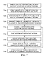
- FIG. 7 is a flowchart of an example process 700 for forming a composite rotorcraft material.
- a length of a fiber optic cable is embedded between layers of composite rotorcraft fibers included in a composite rotorcraft material, e.g., a yoke.
- the length of the fiber optic cable is oriented in a substantially S-shape between the layers.
- an end of the length of the cable is extended to an edge of the composite rotorcraft fibers.
- the end of the length of the cable is terminated at the edge of the composite rotorcraft material.
- a sleeve is positioned to receive the end of the length of the cable.
- the layers of the composite rotorcraft fibers are cured.
- a portion of the sleeve that protrudes out of the edge of the composite rotorcraft material is machined.
- the plug can be removed and a standard connector used to complete the optical circuit.
- the external optical fiber that is connected to complete the optical circuit can be housed in a termination that affixes itself to the secondary section 304.
- the connector can be, e.g., a mechanical link, a clamped joint, a secondarily bonded joint, or any other type of connector.
- a length of fiber can be stored in the secondary portion 304.
- the stored length of fiber can be retrieved and connected to an external fiber via a standard connection, e.g. a connector described above with reference to step 716. If the connection breaks, e.g., the connection is severed, additional stored fiber can be retrieved from the secondary portion 304 and the step 718 can be repeated.
- the external connection may be rigidly affixed to the secondary portion 304 similarly to the removable plug 604.
Abstract
Description
- This application claims priority to
U.S. Patent Application No. 14/310,172 filed on June 20, 2014 - This disclosure relates to monitoring rotorcraft composites.
- Rotor hubs made from thick composite flexures used on helicopters are subject to delamination failures which have strong correlation to the flapping (bending) excursions seen during operations. While these failure modes are benign, the flexure durability life varies with the aircraft usage. The ability to measure this usage (e.g., bending angle excursions) would allow for prediction of what remaining useful life until delamination initiation and enable improved logistical response. In some examples, fiber optic strain sensors can be mounted on a surface of a main rotor flexure to measure the loads in the flexure. Surface mounted sensors can be subjected to high values of strain. Although the sensors can be offset to experience a proportion of the total strain, the output of the sensors can be subject to crosstalk from other loading modes such as torsion. In addition, surface mounted sensors can be exposed to the environment and, consequently, potentially can be damaged.
- This disclosure relates to embedding fiber optic cables in rotorcraft composites.
- Certain aspects of the subject matter described here can be implemented as a method of positioning a fiber optic cable. A portion of a length of a fiber optic cable is embedded between layers of a composite rotorcraft material. A portion of the length of the fiber optic cable is oriented in a substantially S-shape between the layers. An end of the portion of the length of the substantially S-shaped fiber optic cable is extended to an edge of the composite rotorcraft material. The end of the portion of the length of the substantially S-shaped fiber optic cable is terminated at the edge of the composite rotorcraft material.
- This, and other aspects, can include one or more of the following features. The substantially S-shape is defined by a first concave portion and a second concave portion. A first direction of orientation of the first concave portion is opposite a second direction of orientation of the second concave portion. The first direction of orientation of the first concave portion tracks a circumference of an ellipse having a maximum radius and a minimum radius. A ratio of the maximum radius to the minimum radius is about 10:1. An angle by which the fiber optic cable turns along the second concave portion is less than or equal to about 7 degrees. With or without any of the preceding features, the portion of the length of the fiber optic cable can be oriented in a primary direction in which composite fibers of the composite rotorcraft material are oriented. With or without any of the preceding features, the composite rotorcraft material can include a primary portion and a secondary portion that protrudes from the primary portion. The edge of the fiber optic cable can lie in the secondary portion. With or without any of the preceding features, a sleeve can be positioned on the edge of the composite rotorcraft material. The sleeve can receive the end of the portion of the length of the substantially S-shaped fiber optic cable. To terminate the end of the portion of the length of the substantially S-shaped fiber optic cable at the edge of the composite rotorcraft material, the end of the portion of the length of the substantially S-shaped fiber optic cable can be positioned inside the sleeve. To position the sleeve to receive the end of the portion of the length of the substantially S-shaped fiber optic cable, the sleeve can be placed at the edge of the composite rotorcraft material when forming the composite rotorcraft material. A portion of the sleeve can extend out of the edge of the composite rotorcraft material. The composite rotorcraft material can be cured to secure the sleeve at the edge. The portion of the sleeve that extends out of the edge can be machined. With or without any of the preceding features, an axial length of the sleeve can be oriented in a primary direction in which composite fibers of the composite rotorcraft material are oriented. With or without any of the preceding features, a storage section of the composite rotorcraft material can be formed when forming the composite rotorcraft material. A coil of the fiber optic cable can be included in the storage section.
- Certain aspects of the subject matter described here can be implemented as a composite rotorcraft material. The material includes a primary section including multiple composite fibers. The material includes a secondary section attached to a protruding from the primary section. The material includes a fiber optic cable embedded in part between layers of the primary section and in part between layers of the secondary section in a substantially S-shaped orientation. An end of the fiber optic cable terminates at an edge of the protruding section.
- This, and other aspects, can include one or more of the following features. A length of the fiber optic cable embedded between the layers of the primary section can be oriented in a primary direction in which composite fibers of the primary section extend. A sleeve can be positioned on the edge of the secondary section. The sleeve can receive the end of the fiber optic cable. An alignment member can be positioned within the sleeve to align an external fiber optic cable inserted into the sleeve with the fiber optic cable positioned in the sleeve. A removable plug can be positioned between the edge of the secondary section and the end of the fiber optic sleeve positioned in the sleeve. The sleeve can include an inner casing and an outer casing.
- Certain aspects of the subject matter described here can be implemented as a composite rotorcraft material. The material includes a primary section including multiple composite fibers. The material includes a secondary section attached to a protruding from the primary section. The material includes a sleeve positioned on an edge of the secondary section to receive an end of a fiber optic cable embedded in part between layers of the primary section and in part between layers of the secondary section in a substantially S-shaped orientation.
- This, and other aspects, can include one or more of the following features. An alignment member can be positioned within the sleeve to align an external fiber optic cable inserted into the sleeve with the fiber optic cable positioned in the sleeve. A removable plug can be positioned between the edge of the secondary section and the end of the fiber optic sleeve positioned in the sleeve. The sleeve can include an inner casing and an outer casing.
- Certain aspects of the subject matter described here can be implemented as a method of forming a composite rotorcraft material. A length of a fiber optic cable is embedded between layers of composite rotorcraft fibers on a ply boundary plane of the composite rotorcraft material. The length of the fiber optic cable is oriented to include a curvature on the ply boundary plane between the layers. An end of the length of the curved fiber optic cable is extended to an edge of the composite rotorcraft fibers, wherein the end of the length of the curved fiber optic cable terminates at the edge of the composite rotorcraft fibers. The layers of the composite rotorcraft fibers are cured.
- This, and other aspects, can include one or more of the following features. The curvature can result in a substantially S-shaped fiber optic cable. Before curing the layers of the composite rotorcraft fibers, a sleeve can be positioned on the edge of the composite rotorcraft fibers. The sleeve can receive the end of the length of the substantially S-shaped fiber optic cable. The end of the length of the substantially S-shaped fiber optic cable can be positioned inside the sleeve. To position the sleeve to receive the end of the length of the substantially S-shaped fiber optic cable, the sleeve can be placed at the edge of the composite rotorcraft fibers. A portion of the sleeve can extend out of the edge of the composite rotorcraft material.
- Certain aspects of the subject matter described here can be implemented as a method of forming a composite rotorcraft material. A length of a fiber optic cable is embedded between layers of composite rotorcraft fibers on a ply boundary plane of the composite rotorcraft material. A sleeve is positioned on the edge of the composite rotorcraft fibers. The sleeve receives an end of the length of the fiber optic cable that is extended to an edge of the composite rotorcraft fibers and terminates at the edge. The layers of the composite rotorcraft fibers are cured.
- The details of one or more implementations of the subject matter described in this disclosure are set forth in the accompanying drawings and the description below. Other features, aspects, and advantages of the subject matter will become apparent from the description, the drawings, and the claims.
-
-
FIG. 1 is a schematic diagram showing an example of a tiltrotor aircraft. -
FIG. 2 is a schematic diagram showing an example of a rotorcraft. -
FIG. 3 is a schematic diagram showing an example of a rotorcraft yoke with an embedded fiber optic cable. -
FIG. 4 is a schematic diagram showing an orientation of the embedded fiber optic cable in the yoke. -
FIGS. 5A-5C are schematic diagrams showing a portion of the yoke that includes a coil of the fiber optic cable. -
FIGS. 6A-6C are schematic diagrams showing an interface into which an end of the fiber optic cable is embedded. -
FIG. 7 is a flowchart of an example process for forming a composite rotorcraft material. - Like reference numbers and designations in the various drawings indicate like elements.
- This disclosure describes embedding fiber optic cables in rotorcraft composites, e.g., rotorcraft hubs. Helicopter rotors systems use flexible composite structures to provide controlled movement for rotor blades. These structures, such as rotor head flex beams, can experience very high surface strains, which can be in the order of 15,000 µε. Helicopter rotor hubs incorporating the composite flexures are subjected to delamination failures which correlate to bending excursions. Measurement of this deflection can be used to predict the remaining useful life of the flexure and other hub components. However, the high surface strains can make it difficult for the rotorcraft composites to be monitored using surface bonded strain sensors. This disclosure describes embedding the fiber optic cables within the flex beam at a depth where the strain values are more suited to the range of the fiber optic sensing system. Embedding the fiber optic cables as described here can also protect the cables. Such rotorcraft composites embedded with fiber-optic sensors can be implemented as rotorcraft health and usage monitoring systems (HUMS).
- Fiber optic sensors, e.g., fiber bragg gratings, are often better alternatives than traditional, embedded metal or semi conducting sensors because fiber optic sensors are capable of withstanding any processing that would destroy or irreparably damage the metal or semi conducting sensors during the cure cycle of thick composites. The fiber optic sensors can be implemented as fiber optic cables that are on the order of 10x the diameter of composite material fibers. This size correlation between the fiber optic cables and the composite material fibers is a function of the current art form, and to some extent the fragility of the fibers. The fragility can sometimes affect the termination of the embedded fiber optic cable on the external of the thick composite laminate. The embedded fiber optic cable is protected by the composite matrix inside the composite. However, at the point of termination, the fiber optic cable experiences a stiffness change accompanied by a change in vibration/loading environment. Because the single glass fiber is the structural connection between the sensor package and the fiber exiting the structure, fracture may result.
- This disclosure describes techniques to terminate the fiber optic cable at an end surface of a rotorcraft composite. As described below, the fiber optic cable can be oriented in a gradual curve out of the laminate at a low stress/strain region. In addition, an end of the fiber optic cable can be terminated at the edge of the composite at an interface that decreases a possibility of the fiber optic cable fracturing at the edge of the composite. The techniques described here to embed fiber optic cables in rotorcraft composites can decrease the complexity of accurately locating the fiber optic cable during curing. The loads (e.g., shears, moments, or other loads) on the fiber optic cable at the edge of the rotorcraft composite can be decreased. Integrity of the highly polished embedded termination end of the fiber optic cable can be maintained throughout post processing. Intrusion of metal or reinforcing overwrap into the structural portion of the rotorcraft composite can be decreased or avoided. The techniques described here can be implemented as an easy, robust and cheap solution to terminating fiber optic sensors in rotorcraft composites. Implementing the techniques described here can additionally enable fastening a secondary, potentially removable or replaceable, mounting system without compromising the strength of the composite structure. In turn, this can allow N-number of connections, disconnections, maintenance and repair cycles with little to no adverse side effects to the composite structure.
-
FIG. 1 is a schematic diagram of anexample tiltrotor aircraft 101.Aircraft 101 includes afuselage 103 with attachedwings 105.Nacelles 107 are carried at the outboard ends ofwings 105 and are rotatable between the helicopter-mode position shown and a forward-facing airplane-mode position (not shown).Nacelles 107 carry engines andtransmissions 109 for poweringrotor systems 111 in rotation. An engine may be an internal combustion engine, an electrical power source and associated motor, or any other suitable means for poweringrotor system 111. Eachrotor system 111 is illustrated as having threeblades 113. Spinning covers 115 andnacelles 107 substantially enclosetransmission 109, obscuringtransmission 109 from view inFIG. 1 . Thetiltrotor aircraft 101 can includeCF bearing assemblies 120 as part of the coupling between eachblade 113 and therotor systems 111. -
FIG. 2 is a schematic diagram of anexample rotorcraft 201.Rotorcraft 201 has arotor system 203 withmultiple rotor blades 205. The pitch of eachrotor blade 205 can be manipulated in order to selectively control direction, thrust, and lift ofrotorcraft 201. Therotorcraft 201 can includeCF bearing assemblies 220 as part of the coupling between eachblade 205 and therotor system 203. -
FIG. 3 is a schematic diagram showing an example of a rotorcraft yoke 300 (e.g., a flexure or a composite retention element) with an embeddedfiber optic cable 306. Theyoke 300 can include aprimary section 302 which can include and/or be made of multiple composite fibers. Theyoke 300 can also include asecondary section 304 attached to and protruding from theprimary section 302. Theprimary section 302 can be a flexure region or a primary structure that can bear a substantial portion of the load on theyoke 300. Thesecondary section 304 can be a low strain structural attachment region which can bear a significantly smaller load relative to theprimary section 302. r Thesecondary section 304 can function as reinforcement for the termination of thefiber optic cable 306 and/or as an attachment point for an external system that includes a mating sensor and that can connect to thecable 306 to monitor thefiber optic cable 306. For example, the mating element can be a cable which ties to the monitoring unit, such as a fiber optic interrogator. In some implementations, an edge of theyoke 300 can be machined to produce the protrudingsecondary section 304. Thefiber optic cable 306 can be embedded within and curve around the body of theyoke 300, e.g., between layers of theprimary section 302 and between layers of thesecondary section 304. A length of thefiber optic cable 306 embedded between the layers of theprimary section 302 can be oriented in a primary direction in which composite fibers of theprimary section 302 extend. The end of thefiber optic cable 306 can terminate at atermination point 308 in thesecondary section 304 of theyoke 300. -
FIG. 4 is a schematic diagram showing an orientation of the embeddedfiber optic cable 306 in theyoke 300, e.g., a pass through yoke, a race track yoke, or other yoke. Techniques described below can be implemented with reference to other rotorcraft composites, e.g., rotorcraft composites in which embedded fiber optic cables need to be turned to reach a termination point. Examples of other rotorcraft composites can include a dog bone Link or bolt joint configuration. Other examples can include stringers or ribs used in both rotorcraft and fixed wing airframe construction. Additional examples of rotorcraft composites can include rotor blades, airframe structures such as spars, longerons, intercostals, skins, or other structural elements such as cylindrical or conical load-bearing elements, composite lugs, composite beams, or other composite materials. - As shown in
FIG. 4 , thefiber optic cable 306 is embedded in theprimary portion 302, transitions from theprimary portion 302 to thesecondary portion 304, and terminates at thetermination point 308 at the edge of theyoke 300, specifically, in thesecondary portion 304. In some implementations, the length of thefiber optic cable 306, e.g., a portion of the length that transitions from theprimary portion 302 to the secondary portion 304 (length 310), is oriented to include a curvature on the ply boundary plane between the layers of theyoke 300. The curvature can allow thefiber optic cable 306 to gradually exit from the embedded location in theprimary portion 302 toward the edge of theyoke 300 in thesecondary portion 304 in a protected way that does not expose the structure or fiber to risk of failure initiation along the exit path or at the exit point. In some implementations, the portion of the length of thefiber optic cable 306 can be curved in a substantially S-shape, between the layers of theyoke 300. Alternatively, the curvature can have an L, C, U or any other shape. The curvature, e.g., the S-shape can minimize the wrinkling in thefiber optic cable 306 as thecable 306 runs across in the thick part of theyoke 300. The curvature can cause thefiber optic cable 306 to remain in the same ply boundary plane as the remainder of thefiber optic cable 306 that is embedded in theprimary section 302 of theyoke 300. - For example, the substantially S-shape can be defined by a first
concave portion 312 and a secondconcave portion 314. A direction of orientation of the firstconcave portion 312 can be opposite a second direction of orientation of the secondconcave portion 314. The firstconcave portion 312 and the secondconcave portion 314 can represent circumferential portions of afirst ellipse 316 and asecond ellipse 318, respectively. For example, the direction of orientation of the firstconcave portion 312 can track a circumference of thefirst ellipse 316. The direction of orientation of the secondconcave portion 314 can track the circumference of thesecond ellipse 318. The bend radius of each concave portion can be defined by a ratio of the maximum radius and the minimum radius of the respective ellipse. For example, a ratio of the maximum radius to the minimum radius for thefirst ellipse 316 can be high, e.g., greater than 5:1 such as approximately 10:1. In another example, an angle by which thefiber optic cable 306 turns along the secondconcave portion 316 can be small, e.g., less than or equal to approximately 7 degrees. - In general, the
length 310 of thefiber optic cable 306 that transitions from theload bearing portion 302 to thenon-load bearing portion 304 can be positioned in any orientation that decreases or eliminates an inter-laminar shear imparted to thefiber optic cable 306 by a sliding of two layers against one another. For example, a portion of thelength 310 that transitions from theload bearing portion 302 to thenon-load bearing portion 304 can be positioned with a gentle curve having a radius that is at least 100x the diameter of thefiber optic cable 306. Then, a portion of the length that traverses from thenon-load bearing portion 304 to thetermination point 308 can be positioned with an opposing gentle curve having a similar radius. In this manner, thefiber optic cable 306 can be positioned with a low bend radius relative to a 90 degree bend. - As described above, the length of the
fiber optic cable 306 in theload bearing portion 302 can be oriented in a primary direction in which composite fibers of theyoke 300 are oriented. The length of thefiber optic cable 306 in thenon-load bearing portion 304 and near thetermination point 308 can also be oriented in the same direction as the primary direction. The substantially S-shaped orientation can minimize the shear stress on thefiber optic cable 306 as thecable 306 transitions from theload bearing portion 302 to thenon-load bearing portion 304. -
FIGS. 5A-5C are schematic diagrams showing a portion of the yoke that includes a coil of thefiber optic cable 306. In some implementations, the end of thelength 310 of the substantially S-shaped fiber optic cable can be terminated at the edge of theyoke 300, e.g., at thetermination point 308. Alternatively, an excess length of the fiber optic cable can placed in theyoke 300 for removal after curing the laminate. For example,FIG. 5A shows a schematic diagram of theyoke 300, in particular, thenon-load bearing portion 304, including multiple layers (e.g., afirst layer 502, asecond layer 504, and/or other layers) of a plastic material, such as Tedlar® (offered by DuPont™, Inc.) or other type of plastic material. The two layers of the plastic material can be formed into a storage section of theyoke 300. Acoil 506 of thefiber optic cable 306 can be included in the storage section.FIG. 5B shows a schematic diagram of machining the composite rotorcraft material and the plastic material to access the storage section. The plastic material can be a temporary fiber storage material in which thecoil 506 is stored prior to curing theyoke 300.FIG. 5C shows a schematic diagram of accessing thecoil 506 in the storage section. The composite rotorcraft material and the plastic material can be machined to access an end of thecoil 506. In this manner, thecoil 506 of thefiber optic cable 306 can be removed from the edge of theyoke 300. Including thecoil 506 of thefiber optic cable 306 in theyoke 300 can negate having to embed the end of thefiber optic cable 306 in thetermination point 308. -
FIGS. 6A-6C are schematic diagrams showing aninterface 600 into which an end of thefiber optic cable 306 is embedded. Theinterface 600 can be implemented to connect the end of thefiber optic cable 306 at thetermination point 308 to an external monitor, e.g., of the HUMS. For example, the fiber optic cable can be connected to an external light source and an external spectrometer to read returning light and to determine strain from the information represented by the light. The interrogator can be part of the HUMS or a separate unit which itself can be in communication with the HUMS.FIG. 6A is a schematic diagram showing theinterface 600 embedded in theyoke 300. Theinterface 600 can include asleeve 602 positioned on the edge of thesecondary section 304 of theyoke 300. When forming theyoke 300 and/or positioning thefiber optic cable 306 in theyoke 300, thesleeve 602 can be positioned at the edge of thesecondary section 304 and the end of thefiber optic cable 306 can be positioned in thesleeve 602. In some implementations, a portion of thesleeve 602 can protrude into thesecondary section 304 and a remainder of thesleeve 602 can protrude out of thesecondary section 304. In this manner, thesleeve 602 can receive the end of thefiber optic cable 306. -
FIGS. 6A and 6B are schematic diagrams showing aremovable plug 604 positioned in thesleeve 602. Theremovable plug 604 can extend from a position within thenon-load bearing portion 304 of theyoke 300 to a position that is external to the edge of theyoke 300. In other words, theremovable plug 604 can be positioned on either side of the edge of theyoke 300. The end of thefiber optic cable 306 can abut against the end of theremovable plug 602 that is inside thenon-load bearing portion 304 of theyoke 300. Thesleeve 602 can include one ormore alignment members 606. For example, each alignment member can be a ridge formed on aninner casing 605 of thesleeve 602. Prior to curing, thefiber optic cable 306 can be inserted into thesleeve 602 such that the end of thefiber optic cable 306 contacts some of the alignment members when thefiber optic cable 306 is inserted into thesleeve 306. Subsequent to curing, the portion of thesleeve 602 that protrudes out of thesecondary section 304 can be machined such that an outer edge of thesleeve 602 coincides with the edge of theyoke 300. Because a portion of theremovable plug 602 is positioned on either side of the edge of theyoke 300, thesleeve 602 can be machined without affecting the end of thefiber optic cable 306. -
FIG. 6C is a schematic diagram showing a machined surface of theyoke 300. Subsequent to curing theyoke 300 and machining thesleeve 602, the portion of theremovable plug 602 in theyoke 300 can be removed to expose the end of thefiber optic cable 306 and adjacent connection. In some implementations, alignment members can be formed on theinner casing 605 between the end of theremovable plug 604 and the end of thefiber optic cable 306. A fiber optic cable of a monitoring system can be inserted into theopening 608 formed by removing themachined plug 604. The alignment members formed in theinner casing 605 can align the fiber optic cable of the monitoring system with the end of thefiber optic cable 306. Thesleeve 602 can utilize any commercially available or standardized connection type. In general, thesleeve 602 can be any structure that can be implemented as a machine-able removable plug that keeps the connection free from damage after the curing process. -
FIG. 7 is a flowchart of an example process 700 for forming a composite rotorcraft material. At 702, a length of a fiber optic cable is embedded between layers of composite rotorcraft fibers included in a composite rotorcraft material, e.g., a yoke. At 704, the length of the fiber optic cable is oriented in a substantially S-shape between the layers. At 706, an end of the length of the cable is extended to an edge of the composite rotorcraft fibers. At 708, the end of the length of the cable is terminated at the edge of the composite rotorcraft material. In some implementations, at 710, a sleeve is positioned to receive the end of the length of the cable. At 712, the layers of the composite rotorcraft fibers are cured. At 714, a portion of the sleeve that protrudes out of the edge of the composite rotorcraft material is machined. At 716, the plug can be removed and a standard connector used to complete the optical circuit. The external optical fiber that is connected to complete the optical circuit can be housed in a termination that affixes itself to thesecondary section 304. The connector can be, e.g., a mechanical link, a clamped joint, a secondarily bonded joint, or any other type of connector. - In some implementations, a length of fiber can be stored in the
secondary portion 304. At 718, the stored length of fiber can be retrieved and connected to an external fiber via a standard connection, e.g. a connector described above with reference to step 716. If the connection breaks, e.g., the connection is severed, additional stored fiber can be retrieved from thesecondary portion 304 and thestep 718 can be repeated. In such implementations, the external connection may be rigidly affixed to thesecondary portion 304 similarly to theremovable plug 604. - A number of implementations have been described. Nevertheless, it will be understood that various modifications may be made without departing from the spirit and scope of the disclosure.
Claims (15)
- A method of positioning a fiber optic cable, the method comprising:embedding a length of a fiber optic cable between layers of a composite rotorcraft material;orienting a portion of the length of the fiber optic cable in a substantially S-shape between the layers;extending an end of the portion of the length of the substantially S-shaped fiber optic cable to an edge of the composite rotorcraft material; andterminating the end of the portion of the length of the substantially S-shaped fiber optic cable at the edge of the composite rotorcraft material.
- The method of claim 1, wherein the substantially S-shape is defined by a first concave portion and a second concave portion, wherein a first direction of orientation of the first concave portion is opposite a second direction of orientation of the second concave portion.
- The method of claim 2, wherein the first direction of orientation of the first concave portion tracks a circumference of an ellipse having a maximum radius and a minimum radius; and optionally or preferably, wherein a ratio of the maximum radius to the minimum radius is about 10:1.
- The method of claim 2 or claim 3, wherein an angle by which the fiber optic cable turns along the second concave portion is less than or equal to about 7 degrees.
- The method of any preceding claim, further comprising orienting the portion of the length of the fiber optic cable in a primary direction in which composite fibers of the composite rotorcraft material are oriented.
- The method of any preceding claim, wherein the composite rotorcraft material includes a primary portion and a secondary portion that protrudes from the primary portion, and wherein the edge of the fiber optic cable lies in the secondary portion.
- The method of any preceding claim, further comprising positioning, on the edge of the composite rotorcraft material, a sleeve to receive the end of the portion of the length of the substantially S-shaped fiber optic cable, wherein terminating the end of the portion of the length of the substantially S-shaped fiber optic cable at the edge of the composite rotorcraft material comprises positioning the end of the portion of the length of the substantially S-shaped fiber optic inside the sleeve.
- The method of claim 7, wherein positioning the sleeve to receive the end of the portion of the length of the substantially S-shaped fiber optic cable comprises, when forming the composite rotorcraft material:placing the sleeve at the edge of the composite rotorcraft material, wherein a portion of the sleeve extends out of the edge of the composite rotorcraft material;curing the composite rotorcraft material to secure the sleeve at the edge; andmachining the portion of the sleeve that extends out of the edge; and optionally or preferably, further comprising orienting an axial length of the sleeve in a primary direction in which composite fibers of the composite rotorcraft material are oriented.
- The method of any preceding claim, further comprising, when forming the composite rotorcraft material:forming a storage section of the composite rotorcraft material; andincluding a coil of the fiber optic cable in the storage section.
- A composite rotorcraft material comprising:a primary section including a plurality of composite fibers;a secondary section attached to and protruding from the primary section; anda fiber optic cable embedded in part between layers of the primary section and in part between layers of the secondary section in a substantially S-shaped orientation, wherein an end of the fiber optic cable terminates at an edge of the protruding section.
- The material of claim 10, wherein a length of the fiber optic cable embedded between the layers of the primary section is oriented in a primary direction in which composite fibers of the primary section extend.
- The material of claim 10 or claim 11, further comprising a sleeve positioned on the edge of the secondary section, the sleeve to receive the end of the fiber optic cable; and optionally or preferably, further comprising:i) an alignment member positioned within the sleeve to align an external fiber optic cable inserted into the sleeve with the fiber optic cable positioned in the sleeve; and/or.ii) a removable plug positioned between the edge of the secondary section and the end of the fiber optic sleeve positioned in the sleeve.
- The material of claim 12, wherein the sleeve includes an inner casing and an outer casing.
- A method of forming a composite rotorcraft material, the method comprising:embedding a length of a fiber optic cable between layers of composite rotorcraft fibers on a ply boundary plane of the composite rotorcraft material;orienting the length of the fiber optic cable to include a curvature on the ply boundary plane between the layers;extending an end of the length of the curved fiber optic cable to an edge of the composite rotorcraft fibers, wherein the end of the length of the curved fiber optic cable terminates at the edge of the composite rotorcraft fibers; andcuring the layers of the composite rotorcraft fibers.
- The method of claim 14, wherein the curvature results in a substantially S-shaped fiber optic cable, and wherein the method further comprises, before curing the layers of the composite rotorcraft fibers:positioning, on the edge of the composite rotorcraft fibers, a sleeve to receive the end of the length of the substantially S-shaped fiber optic cable; andpositioning the end of the length of the substantially S-shaped fiber optic inside the sleeve, and optionally or preferably, wherein positioning the sleeve to receive the end of the length of the substantially S-shaped fiber optic cable comprises placing the sleeve at the edge of the composite rotorcraft fibers, wherein a portion of the sleeve extends out of the edge of the composite rotorcraft material.
Applications Claiming Priority (1)
| Application Number | Priority Date | Filing Date | Title |
|---|---|---|---|
| US14/310,172 US9500561B2 (en) | 2014-06-20 | 2014-06-20 | Embedding fiber optic cables in rotorcraft composites |
Publications (2)
| Publication Number | Publication Date |
|---|---|
| EP2957884A1 true EP2957884A1 (en) | 2015-12-23 |
| EP2957884B1 EP2957884B1 (en) | 2017-05-17 |
Family
ID=53397938
Family Applications (1)
| Application Number | Title | Priority Date | Filing Date |
|---|---|---|---|
| EP15172054.7A Active EP2957884B1 (en) | 2014-06-20 | 2015-06-15 | Embedding fiber optic cables in rotorcraft composites |
Country Status (3)
| Country | Link |
|---|---|
| US (1) | US9500561B2 (en) |
| EP (1) | EP2957884B1 (en) |
| CA (1) | CA2894905C (en) |
Families Citing this family (4)
| Publication number | Priority date | Publication date | Assignee | Title |
|---|---|---|---|---|
| US10337935B2 (en) | 2016-12-12 | 2019-07-02 | Sikorsky Aircraft Corporation | Systems and methods for integrated, multi-functional, fault tolerant sensing and communication |
| US10605631B2 (en) | 2017-08-03 | 2020-03-31 | Sikorsky Aircraft Corporation | Structural pi joint with integrated fiber optic sensing |
| US10960463B2 (en) * | 2018-11-14 | 2021-03-30 | International Business Machines Corporation | Embedding thermally-resistant flexible cabling within a metal casting during die-casting |
| US10705298B1 (en) | 2019-04-26 | 2020-07-07 | Lockheed Martin Corporation | Fiber optic protective box for core-stiffened composite structures |
Citations (4)
| Publication number | Priority date | Publication date | Assignee | Title |
|---|---|---|---|---|
| US4936649A (en) * | 1989-01-25 | 1990-06-26 | Lymer John D | Damage evaluation system and method using optical fibers |
| US5015842A (en) * | 1989-06-01 | 1991-05-14 | United Technologies Corporation | High density fiber optic damage detection system |
| US5142141A (en) * | 1990-09-19 | 1992-08-25 | The Boeing Company | Crack growth measurement network with primary and shunt optical fibers |
| US20050259909A1 (en) * | 2003-12-22 | 2005-11-24 | Aldridge Nigel B | Fibre optic connectors and methods |
Family Cites Families (14)
| Publication number | Priority date | Publication date | Assignee | Title |
|---|---|---|---|---|
| US3910105A (en) * | 1974-08-16 | 1975-10-07 | Boeing Co | Method for detection of flaws in composite fiberglass structures |
| DE3131870A1 (en) * | 1981-08-12 | 1983-02-24 | Philips Kommunikations Industrie AG, 8500 Nürnberg | COMPONENT-MONITORABLE COMPONENT BY means of fiber-optic cables |
| US4836030A (en) * | 1985-05-20 | 1989-06-06 | Lockheed Corporation | Method of testing composite materials for structural damage |
| US4888076A (en) * | 1988-07-05 | 1989-12-19 | Lockheed Corporation | Method of coupling optical fibers enbedded in a molded article to the exterior thereof |
| US5299273A (en) * | 1992-11-12 | 1994-03-29 | Teledyne Ryan Aeronautical | Optical fiber to laminate adapter |
| US5399854A (en) * | 1994-03-08 | 1995-03-21 | United Technologies Corporation | Embedded optical sensor capable of strain and temperature measurement using a single diffraction grating |
| US5568582A (en) * | 1994-10-13 | 1996-10-22 | Martin Marietta Energy Systems, Inc. | Fiber optic connector |
| US6035084A (en) * | 1997-11-13 | 2000-03-07 | Mcdonell Douglas Corporation | Fiber optic connector and associated method for establishing an optical connection with an optical fiber embedded within a composite structure |
| US6061902A (en) * | 1998-04-21 | 2000-05-16 | Dalhousie University | Method for recovering leads embedded within a composite structure |
| EP1340061A4 (en) * | 2000-12-07 | 2005-01-19 | Univ Nanyang | Fiber optic force sensor |
| US6547448B2 (en) * | 2001-05-15 | 2003-04-15 | The Boeing Company | Embeddable fiber optic connector and associated method |
| JP3720790B2 (en) * | 2002-04-18 | 2005-11-30 | 川崎重工業株式会社 | Method for manufacturing structure in which optical transmission medium is embedded |
| ES2672789T3 (en) * | 2004-01-23 | 2018-06-18 | Lm Wind Power International Technology Ii Aps | Device that includes a system adapted for use in temperature compensation of tension measurements of fiber reinforced structures |
| AU2005338588B2 (en) * | 2005-11-30 | 2013-01-24 | Airbus Operations, S.L. | Composite material structure with embedded optical fibre and method for repairing same |
-
2014
- 2014-06-20 US US14/310,172 patent/US9500561B2/en active Active
-
2015
- 2015-06-15 EP EP15172054.7A patent/EP2957884B1/en active Active
- 2015-06-17 CA CA2894905A patent/CA2894905C/en active Active
Patent Citations (4)
| Publication number | Priority date | Publication date | Assignee | Title |
|---|---|---|---|---|
| US4936649A (en) * | 1989-01-25 | 1990-06-26 | Lymer John D | Damage evaluation system and method using optical fibers |
| US5015842A (en) * | 1989-06-01 | 1991-05-14 | United Technologies Corporation | High density fiber optic damage detection system |
| US5142141A (en) * | 1990-09-19 | 1992-08-25 | The Boeing Company | Crack growth measurement network with primary and shunt optical fibers |
| US20050259909A1 (en) * | 2003-12-22 | 2005-11-24 | Aldridge Nigel B | Fibre optic connectors and methods |
Non-Patent Citations (1)
| Title |
|---|
| LU Z J ET AL: "APPLICATION ISSUES OF FIBER OPTIC SENSORS IN AIRCRAFT STRUCTURES", PROCEEDINGS OF SPIE, S P I E - INTERNATIONAL SOCIETY FOR OPTICAL ENGINEERING, US, vol. 1588, 1 September 1991 (1991-09-01), pages 276 - 281, XP008030419, ISSN: 0277-786X, ISBN: 978-1-62841-684-8, DOI: 10.1117/12.50186 * |
Also Published As
| Publication number | Publication date |
|---|---|
| US20150370030A1 (en) | 2015-12-24 |
| CA2894905A1 (en) | 2015-12-20 |
| EP2957884B1 (en) | 2017-05-17 |
| US9500561B2 (en) | 2016-11-22 |
| CA2894905C (en) | 2017-08-01 |
Similar Documents
| Publication | Publication Date | Title |
|---|---|---|
| CA2894905C (en) | Embedding fiber optic cables in rotorcraft composites | |
| US9840921B2 (en) | Blade anchored securely in radial translation, propeller, turbine engine and aircraft | |
| US11084604B2 (en) | Aircraft rotor with embedded optical fiber sensor | |
| US8272841B2 (en) | Propeller blade retention | |
| US10689104B2 (en) | Tail rotor integrated damper attachment | |
| EP3013687B1 (en) | Joint assembly and method of forming thereof | |
| EP3628588B1 (en) | Design and inspection method of aircraft drive shafts | |
| EP2927121B1 (en) | Modular rotor craft rotor hub system | |
| US10605631B2 (en) | Structural pi joint with integrated fiber optic sensing | |
| US20230312088A1 (en) | Securing assembly for a rotor blade | |
| US8858183B2 (en) | Rotor blade for a rotary-wing aircraft | |
| JP6301461B2 (en) | System and method for blade mounting | |
| US10705298B1 (en) | Fiber optic protective box for core-stiffened composite structures | |
| Reddick Jr | Safe-life and damage-tolerant design approaches for helicopter structures | |
| Saxena | Primary control of a Mach scale swashplateless rotor using brushless DC motor actuated trailing edge flaps | |
| EP3588038A1 (en) | A measuring apparatus for determining loads caused by moments and forces | |
| Hall | General Survey and Evaluation of Current Procedures | |
| Dey et al. | Finite element-based reliability analysis of composite structures | |
| Ford | The European Rotorcraft Forum | |
| Needham et al. | Failsafe/Safe-Life Interface Criteria | |
| Jessop et al. | Wind tunnel testing of a Eurofar tilt rotor aeroelastic stability | |
| PIMM | Flight certification testing for the A-7D advanced composite outer wing panel |
Legal Events
| Date | Code | Title | Description |
|---|---|---|---|
| PUAI | Public reference made under article 153(3) epc to a published international application that has entered the european phase |
Free format text: ORIGINAL CODE: 0009012 |
|
| 17P | Request for examination filed |
Effective date: 20150615 |
|
| AK | Designated contracting states |
Kind code of ref document: A1 Designated state(s): AL AT BE BG CH CY CZ DE DK EE ES FI FR GB GR HR HU IE IS IT LI LT LU LV MC MK MT NL NO PL PT RO RS SE SI SK SM TR |
|
| AX | Request for extension of the european patent |
Extension state: BA ME |
|
| GRAP | Despatch of communication of intention to grant a patent |
Free format text: ORIGINAL CODE: EPIDOSNIGR1 |
|
| INTG | Intention to grant announced |
Effective date: 20161125 |
|
| GRAS | Grant fee paid |
Free format text: ORIGINAL CODE: EPIDOSNIGR3 |
|
| GRAJ | Information related to disapproval of communication of intention to grant by the applicant or resumption of examination proceedings by the epo deleted |
Free format text: ORIGINAL CODE: EPIDOSDIGR1 |
|
| GRAL | Information related to payment of fee for publishing/printing deleted |
Free format text: ORIGINAL CODE: EPIDOSDIGR3 |
|
| INTC | Intention to grant announced (deleted) | ||
| GRAR | Information related to intention to grant a patent recorded |
Free format text: ORIGINAL CODE: EPIDOSNIGR71 |
|
| GRAA | (expected) grant |
Free format text: ORIGINAL CODE: 0009210 |
|
| INTG | Intention to grant announced |
Effective date: 20170406 |
|
| AK | Designated contracting states |
Kind code of ref document: B1 Designated state(s): AL AT BE BG CH CY CZ DE DK EE ES FI FR GB GR HR HU IE IS IT LI LT LU LV MC MK MT NL NO PL PT RO RS SE SI SK SM TR |
|
| REG | Reference to a national code |
Ref country code: GB Ref legal event code: FG4D |
|
| REG | Reference to a national code |
Ref country code: CH Ref legal event code: EP |
|
| REG | Reference to a national code |
Ref country code: IE Ref legal event code: FG4D |
|
| REG | Reference to a national code |
Ref country code: AT Ref legal event code: REF Ref document number: 894900 Country of ref document: AT Kind code of ref document: T Effective date: 20170615 |
|
| REG | Reference to a national code |
Ref country code: FR Ref legal event code: PLFP Year of fee payment: 3 |
|
| REG | Reference to a national code |
Ref country code: DE Ref legal event code: R096 Ref document number: 602015002724 Country of ref document: DE |
|
| REG | Reference to a national code |
Ref country code: NL Ref legal event code: MP Effective date: 20170517 |
|
| REG | Reference to a national code |
Ref country code: LT Ref legal event code: MG4D |
|
| REG | Reference to a national code |
Ref country code: AT Ref legal event code: MK05 Ref document number: 894900 Country of ref document: AT Kind code of ref document: T Effective date: 20170517 |
|
| PG25 | Lapsed in a contracting state [announced via postgrant information from national office to epo] |
Ref country code: ES Free format text: LAPSE BECAUSE OF FAILURE TO SUBMIT A TRANSLATION OF THE DESCRIPTION OR TO PAY THE FEE WITHIN THE PRESCRIBED TIME-LIMIT Effective date: 20170517 Ref country code: NO Free format text: LAPSE BECAUSE OF FAILURE TO SUBMIT A TRANSLATION OF THE DESCRIPTION OR TO PAY THE FEE WITHIN THE PRESCRIBED TIME-LIMIT Effective date: 20170817 Ref country code: FI Free format text: LAPSE BECAUSE OF FAILURE TO SUBMIT A TRANSLATION OF THE DESCRIPTION OR TO PAY THE FEE WITHIN THE PRESCRIBED TIME-LIMIT Effective date: 20170517 Ref country code: GR Free format text: LAPSE BECAUSE OF FAILURE TO SUBMIT A TRANSLATION OF THE DESCRIPTION OR TO PAY THE FEE WITHIN THE PRESCRIBED TIME-LIMIT Effective date: 20170818 Ref country code: HR Free format text: LAPSE BECAUSE OF FAILURE TO SUBMIT A TRANSLATION OF THE DESCRIPTION OR TO PAY THE FEE WITHIN THE PRESCRIBED TIME-LIMIT Effective date: 20170517 Ref country code: LT Free format text: LAPSE BECAUSE OF FAILURE TO SUBMIT A TRANSLATION OF THE DESCRIPTION OR TO PAY THE FEE WITHIN THE PRESCRIBED TIME-LIMIT Effective date: 20170517 Ref country code: AT Free format text: LAPSE BECAUSE OF FAILURE TO SUBMIT A TRANSLATION OF THE DESCRIPTION OR TO PAY THE FEE WITHIN THE PRESCRIBED TIME-LIMIT Effective date: 20170517 |
|
| PG25 | Lapsed in a contracting state [announced via postgrant information from national office to epo] |
Ref country code: LV Free format text: LAPSE BECAUSE OF FAILURE TO SUBMIT A TRANSLATION OF THE DESCRIPTION OR TO PAY THE FEE WITHIN THE PRESCRIBED TIME-LIMIT Effective date: 20170517 Ref country code: IS Free format text: LAPSE BECAUSE OF FAILURE TO SUBMIT A TRANSLATION OF THE DESCRIPTION OR TO PAY THE FEE WITHIN THE PRESCRIBED TIME-LIMIT Effective date: 20170917 Ref country code: NL Free format text: LAPSE BECAUSE OF FAILURE TO SUBMIT A TRANSLATION OF THE DESCRIPTION OR TO PAY THE FEE WITHIN THE PRESCRIBED TIME-LIMIT Effective date: 20170517 Ref country code: RS Free format text: LAPSE BECAUSE OF FAILURE TO SUBMIT A TRANSLATION OF THE DESCRIPTION OR TO PAY THE FEE WITHIN THE PRESCRIBED TIME-LIMIT Effective date: 20170517 Ref country code: BG Free format text: LAPSE BECAUSE OF FAILURE TO SUBMIT A TRANSLATION OF THE DESCRIPTION OR TO PAY THE FEE WITHIN THE PRESCRIBED TIME-LIMIT Effective date: 20170817 Ref country code: PL Free format text: LAPSE BECAUSE OF FAILURE TO SUBMIT A TRANSLATION OF THE DESCRIPTION OR TO PAY THE FEE WITHIN THE PRESCRIBED TIME-LIMIT Effective date: 20170517 Ref country code: SE Free format text: LAPSE BECAUSE OF FAILURE TO SUBMIT A TRANSLATION OF THE DESCRIPTION OR TO PAY THE FEE WITHIN THE PRESCRIBED TIME-LIMIT Effective date: 20170517 |
|
| PG25 | Lapsed in a contracting state [announced via postgrant information from national office to epo] |
Ref country code: CZ Free format text: LAPSE BECAUSE OF FAILURE TO SUBMIT A TRANSLATION OF THE DESCRIPTION OR TO PAY THE FEE WITHIN THE PRESCRIBED TIME-LIMIT Effective date: 20170517 Ref country code: SK Free format text: LAPSE BECAUSE OF FAILURE TO SUBMIT A TRANSLATION OF THE DESCRIPTION OR TO PAY THE FEE WITHIN THE PRESCRIBED TIME-LIMIT Effective date: 20170517 Ref country code: DK Free format text: LAPSE BECAUSE OF FAILURE TO SUBMIT A TRANSLATION OF THE DESCRIPTION OR TO PAY THE FEE WITHIN THE PRESCRIBED TIME-LIMIT Effective date: 20170517 Ref country code: RO Free format text: LAPSE BECAUSE OF FAILURE TO SUBMIT A TRANSLATION OF THE DESCRIPTION OR TO PAY THE FEE WITHIN THE PRESCRIBED TIME-LIMIT Effective date: 20170517 Ref country code: EE Free format text: LAPSE BECAUSE OF FAILURE TO SUBMIT A TRANSLATION OF THE DESCRIPTION OR TO PAY THE FEE WITHIN THE PRESCRIBED TIME-LIMIT Effective date: 20170517 |
|
| REG | Reference to a national code |
Ref country code: DE Ref legal event code: R097 Ref document number: 602015002724 Country of ref document: DE |
|
| PG25 | Lapsed in a contracting state [announced via postgrant information from national office to epo] |
Ref country code: SM Free format text: LAPSE BECAUSE OF FAILURE TO SUBMIT A TRANSLATION OF THE DESCRIPTION OR TO PAY THE FEE WITHIN THE PRESCRIBED TIME-LIMIT Effective date: 20170517 |
|
| REG | Reference to a national code |
Ref country code: IE Ref legal event code: MM4A |
|
| PLBE | No opposition filed within time limit |
Free format text: ORIGINAL CODE: 0009261 |
|
| STAA | Information on the status of an ep patent application or granted ep patent |
Free format text: STATUS: NO OPPOSITION FILED WITHIN TIME LIMIT |
|
| 26N | No opposition filed |
Effective date: 20180220 |
|
| PG25 | Lapsed in a contracting state [announced via postgrant information from national office to epo] |
Ref country code: LU Free format text: LAPSE BECAUSE OF NON-PAYMENT OF DUE FEES Effective date: 20170615 Ref country code: IE Free format text: LAPSE BECAUSE OF NON-PAYMENT OF DUE FEES Effective date: 20170615 |
|
| REG | Reference to a national code |
Ref country code: BE Ref legal event code: MM Effective date: 20170630 |
|
| PG25 | Lapsed in a contracting state [announced via postgrant information from national office to epo] |
Ref country code: SI Free format text: LAPSE BECAUSE OF FAILURE TO SUBMIT A TRANSLATION OF THE DESCRIPTION OR TO PAY THE FEE WITHIN THE PRESCRIBED TIME-LIMIT Effective date: 20170517 |
|
| REG | Reference to a national code |
Ref country code: FR Ref legal event code: PLFP Year of fee payment: 4 |
|
| PG25 | Lapsed in a contracting state [announced via postgrant information from national office to epo] |
Ref country code: BE Free format text: LAPSE BECAUSE OF NON-PAYMENT OF DUE FEES Effective date: 20170630 |
|
| PG25 | Lapsed in a contracting state [announced via postgrant information from national office to epo] |
Ref country code: MT Free format text: LAPSE BECAUSE OF NON-PAYMENT OF DUE FEES Effective date: 20170615 |
|
| REG | Reference to a national code |
Ref country code: CH Ref legal event code: PL |
|
| PG25 | Lapsed in a contracting state [announced via postgrant information from national office to epo] |
Ref country code: LI Free format text: LAPSE BECAUSE OF NON-PAYMENT OF DUE FEES Effective date: 20180630 Ref country code: CH Free format text: LAPSE BECAUSE OF NON-PAYMENT OF DUE FEES Effective date: 20180630 |
|
| PG25 | Lapsed in a contracting state [announced via postgrant information from national office to epo] |
Ref country code: HU Free format text: LAPSE BECAUSE OF FAILURE TO SUBMIT A TRANSLATION OF THE DESCRIPTION OR TO PAY THE FEE WITHIN THE PRESCRIBED TIME-LIMIT; INVALID AB INITIO Effective date: 20150615 Ref country code: MC Free format text: LAPSE BECAUSE OF FAILURE TO SUBMIT A TRANSLATION OF THE DESCRIPTION OR TO PAY THE FEE WITHIN THE PRESCRIBED TIME-LIMIT Effective date: 20170517 |
|
| PG25 | Lapsed in a contracting state [announced via postgrant information from national office to epo] |
Ref country code: CY Free format text: LAPSE BECAUSE OF FAILURE TO SUBMIT A TRANSLATION OF THE DESCRIPTION OR TO PAY THE FEE WITHIN THE PRESCRIBED TIME-LIMIT Effective date: 20170517 |
|
| PG25 | Lapsed in a contracting state [announced via postgrant information from national office to epo] |
Ref country code: MK Free format text: LAPSE BECAUSE OF FAILURE TO SUBMIT A TRANSLATION OF THE DESCRIPTION OR TO PAY THE FEE WITHIN THE PRESCRIBED TIME-LIMIT Effective date: 20170517 |
|
| PG25 | Lapsed in a contracting state [announced via postgrant information from national office to epo] |
Ref country code: TR Free format text: LAPSE BECAUSE OF FAILURE TO SUBMIT A TRANSLATION OF THE DESCRIPTION OR TO PAY THE FEE WITHIN THE PRESCRIBED TIME-LIMIT Effective date: 20170517 |
|
| PG25 | Lapsed in a contracting state [announced via postgrant information from national office to epo] |
Ref country code: PT Free format text: LAPSE BECAUSE OF FAILURE TO SUBMIT A TRANSLATION OF THE DESCRIPTION OR TO PAY THE FEE WITHIN THE PRESCRIBED TIME-LIMIT Effective date: 20170517 |
|
| PG25 | Lapsed in a contracting state [announced via postgrant information from national office to epo] |
Ref country code: AL Free format text: LAPSE BECAUSE OF FAILURE TO SUBMIT A TRANSLATION OF THE DESCRIPTION OR TO PAY THE FEE WITHIN THE PRESCRIBED TIME-LIMIT Effective date: 20170517 |
|
| P01 | Opt-out of the competence of the unified patent court (upc) registered |
Effective date: 20230602 |
|
| PGFP | Annual fee paid to national office [announced via postgrant information from national office to epo] |
Ref country code: FR Payment date: 20230626 Year of fee payment: 9 Ref country code: DE Payment date: 20230626 Year of fee payment: 9 |
|
| PGFP | Annual fee paid to national office [announced via postgrant information from national office to epo] |
Ref country code: IT Payment date: 20230620 Year of fee payment: 9 Ref country code: GB Payment date: 20230627 Year of fee payment: 9 |