EP2927121B1 - Modular rotor craft rotor hub system - Google Patents
Modular rotor craft rotor hub system Download PDFInfo
- Publication number
- EP2927121B1 EP2927121B1 EP15162498.8A EP15162498A EP2927121B1 EP 2927121 B1 EP2927121 B1 EP 2927121B1 EP 15162498 A EP15162498 A EP 15162498A EP 2927121 B1 EP2927121 B1 EP 2927121B1
- Authority
- EP
- European Patent Office
- Prior art keywords
- pitch
- bearing
- bearings
- rotor
- arm assembly
- Prior art date
- Legal status (The legal status is an assumption and is not a legal conclusion. Google has not performed a legal analysis and makes no representation as to the accuracy of the status listed.)
- Active
Links
Images


Classifications
-
- B—PERFORMING OPERATIONS; TRANSPORTING
- B64—AIRCRAFT; AVIATION; COSMONAUTICS
- B64C—AEROPLANES; HELICOPTERS
- B64C27/00—Rotorcraft; Rotors peculiar thereto
- B64C27/32—Rotors
- B64C27/35—Rotors having elastomeric joints
-
- B—PERFORMING OPERATIONS; TRANSPORTING
- B64—AIRCRAFT; AVIATION; COSMONAUTICS
- B64C—AEROPLANES; HELICOPTERS
- B64C27/00—Rotorcraft; Rotors peculiar thereto
- B64C27/32—Rotors
- B64C27/37—Rotors having articulated joints
- B64C27/39—Rotors having articulated joints with individually articulated blades, i.e. with flapping or drag hinges
-
- B—PERFORMING OPERATIONS; TRANSPORTING
- B64—AIRCRAFT; AVIATION; COSMONAUTICS
- B64C—AEROPLANES; HELICOPTERS
- B64C27/00—Rotorcraft; Rotors peculiar thereto
- B64C27/54—Mechanisms for controlling blade adjustment or movement relative to rotor head, e.g. lag-lead movement
-
- Y—GENERAL TAGGING OF NEW TECHNOLOGICAL DEVELOPMENTS; GENERAL TAGGING OF CROSS-SECTIONAL TECHNOLOGIES SPANNING OVER SEVERAL SECTIONS OF THE IPC; TECHNICAL SUBJECTS COVERED BY FORMER USPC CROSS-REFERENCE ART COLLECTIONS [XRACs] AND DIGESTS
- Y10—TECHNICAL SUBJECTS COVERED BY FORMER USPC
- Y10T—TECHNICAL SUBJECTS COVERED BY FORMER US CLASSIFICATION
- Y10T29/00—Metal working
- Y10T29/49—Method of mechanical manufacture
- Y10T29/49316—Impeller making
- Y10T29/49332—Propeller making
Definitions
- the present disclosure relates to a modular rotor craft rotor hub system and methods of assembling the same, and more particularly, to a modular rotor craft rotor hub system that includes fully articulated rotor arm assemblies having discrete bearings for each degree of freedom.
- a key component of a rotor craft is the main rotor hub system. It provides attachment of the main rotor blades during operation. Rotational power is delivered to the main rotor hub system to provide rotational velocity to the blades in order to create aerodynamic lift.
- the main rotor hub system must allow for rotational motion of the blades in the vertical (flap), horizontal (lead-lag), and axial (pitch) directions near the blade root attachment with the hub to accommodate flight control authority and dynamic stability.
- Main rotor hub systems that accommodate these motions with discrete hinge mechanisms are referred to as fully articulated hub systems.
- At least some known fully articulated rotor hub systems provide beneficial design kinematics, but struggle to provide these rotational freedoms with bearing systems that can accommodate high frequency and high amplitude oscillatory motion under high thrust loading created by the centrifugal force of the rotating blades.
- One known hub system is a non-friction bearing system such as a ball or roller bearing system. The lubricants and seals of these types of bearing systems are susceptible to moisture extrusion and leakage and therefore demand frequent maintenance that often requires removal and disassembly of the entire rotor hub to service.
- Another known hub system is a strap pack hub system that includes stretch straps formed from expensive specialized steel.
- US2003108258 describes a self-aligning dynamic hinge sleeve for attachment to a pitch hinge in a position that places the hinge sleeve in contact with a pitch bearing.
- US3589835 describes a mutlibladed rotor with the blades connected to the hub by a hinge mechanism and with a variable stiffness spring extending between the hub and the blade.
- EP1752375 describes a method for producing an elastomeric conical flap bearing assembly for rotary aircraft including an inboard bearing element and outboard bearing element disposed within an outer housing.
- US2006027957 describes an elastomeric bearing having inner and outer races and a core.
- US6309182 describes a droop stop mechanism for controlling droop of a rotor assembly in both static and dynamic states.
- RU2376201 describes a rotor design comprising blades, rotor hub with lugs and blade-to-hub joints.
- spherical elastomeric bearings have similar footprints to non-friction and strap pack hubs, but the dynamics and kinematics are much different, requiring significant research and development costs to implement a spherical elastomeric bearing hub system on an aircraft having strap-pack or roller bearing based legacy hubs.
- each rotor arm assembly includes a pitch shaft having a first portion and a second portion perpendicular to the first portion. A pair of flap bearings are coupled to the second portion.
- An inboard pitch bearing is coupled to the first portion proximate the second portion and an outboard pitch bearing is coupled at a distal end of the first portion.
- the pair of flap bearings, the inboard pitch bearing, and the outboard pitch bearing are discrete elastomeric bearings configured to facilitate movement of the rotor arm assembly about a plurality of degrees of freedom, wherein no two or more degrees of freedom are accommodated by a single bearing.
- implementations of the disclosure may be described in the context of an aircraft manufacturing and service method 100 and via an aircraft 102 (shown in FIG. 2 ).
- pre-production including specification and design 104 data of aircraft 102 may be used during the manufacturing process and other materials associated with the airframe may be procured 106.
- component and subassembly manufacturing 108 and system integration 110 of aircraft 102 occurs, prior to aircraft 102 entering its certification and delivery process 112.
- aircraft 102 may be placed in service 114.
- aircraft 102 is scheduled for periodic, routine, and scheduled maintenance and service 116, including any modification, reconfiguration, and/or refurbishment, for example.
- manufacturing and service method 100 may be implemented via vehicles other than an aircraft.
- Each portion and process associated with aircraft manufacturing and/or service 100 may be performed or completed by a system integrator, a third party, and/or an operator (e.g., a customer).
- a system integrator may include without limitation any number of aircraft manufacturers and major-system subcontractors
- a third party may include without limitation any number of venders, subcontractors, and suppliers
- an operator may be an airline, leasing company, military entity, service organization, and so on.
- aircraft 102 produced via method 100 may include an airframe 118 having a plurality of systems 120 and an interior 122.
- high-level systems 120 include one or more of a propulsion system 124, an electrical system 126, a hydraulic system 128, and/or an environmental system 130. Any number of other systems may be included.
- Apparatus and methods embodied herein may be employed during any one or more of the stages of method 100.
- components or subassemblies corresponding to component production process 108 may be fabricated or manufactured in a manner similar to components or subassemblies produced while aircraft 102 is in service.
- one or more apparatus implementations, method implementations, or a combination thereof may be utilized during the production stages 108 and 110, for example, by substantially expediting assembly of, and/or reducing the cost of assembly of aircraft 102.
- apparatus implementations, method implementations, or a combination thereof may be utilized while aircraft 102 is being serviced or maintained, for example, during scheduled maintenance and service 116.
- aircraft may include, but is not limited to, airplanes, unmanned aerial vehicles (UAVs), gliders, helicopters, rotor craft, and/or any other object that travels through airspace.
- UAVs unmanned aerial vehicles
- helicopters helicopters
- rotor craft and/or any other object that travels through airspace.
- aircraft manufacturing and service method described herein may be used in any manufacturing and/or service operation.
- FIG. 3 illustrates an aircraft 200, which may be substantially similar to aircraft 102.
- aircraft 200 is a rotor craft that includes a fuselage 202 having a forward section 204 and an aft section 206 (e.g., a tail section) rearward of forward section 204.
- rotor craft may include any heavier-than-air flying craft that uses rotor blades revolving around a mast to generate and sustain lift. Examples of rotor craft may include, but are not limited to, helicopters, tilt-rotor aircraft, cyclocopters, and gyroynes.
- Rotor craft 200 also includes a rotor hub system 208, extending upwards from forward section 204 of fuselage 202, and a plurality of rotor blades 210 coupled to rotor hub system 208 configured for rotation about a rotor axis 212.
- rotor craft 200 may include more than one rotor hub system 208.
- rotor hub system 208 includes four rotor blades, for example, a first rotor blade 214, a second rotor blade 216, a third rotor blade 218, and a fourth rotor blade 220.
- the rotor blades are evenly spaced.
- the blades are spaced at 90 degree intervals. For a six blade configuration, the spacing would be at 60 degrees.
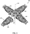
- FIG. 4 is a perspective view of rotor hub system 208 including a center body 222 and a plurality of rotor arm assemblies 224.
- the plurality of rotor arm assemblies 224 includes a first rotor arm assembly 226 configured to couple first rotor blade 214 to hub system 208, a second rotor arm assembly 228 configured to couple second rotor blade 216 to hub system 208, a third rotor arm assembly 230 configured to couple third rotor blade 218 to hub system 208, and a fourth rotor arm assembly 232 configured to couple fourth rotor blade 220 to hub system 208.
- FIG. 1 illustrates that incorporate fewer or additional rotor arm assemblies 224.
- rotor hub system 208 is a fully-articulated rotor system, i.e., a system which rotates about axis 212 and in which each of rotor blades 210 are permitted pitching, flapping and lead-lag movement about a respective pitch axis 234, flap axis 236 and lead-lag axis 238.
- rotor arm assemblies 224 provide a respective rotor blade 210 with a pitch motion about pitch axis 234 in the range of between approximately +/-40° from nominal, a flapping motion about flap axis 236 in the range of between approximately -10° and 30° from nominal, and a lead-lag motion about lead-lag axis 238 in the range of between approximately +/-10° from nominal.
- rotor arm assemblies may provide for pitch, flapping, and lead-lag motion about respective axes within any range that facilitates operation of rotor arm assemblies 224 as described herein.
- each rotor arm assembly 224 includes a plurality of discrete elastomeric bearings such that no two or more degrees of freedom are facilitated by a single bearing.
- first rotor arm assembly 226 includes a pair of elastomeric flap bearings 240, an elastomeric thrust bearing 242, and a plurality of concentric elastomeric pitch bearings 244 including an inboard pitch bearing 246 and an outboard pitch bearing 248.
- inboard' is meant to describe being closer to center body 222 and rotational axis 212
- the term “outboard” is meant to describe being closer to lead-lag axis 238 and a respective one of the plurality of rotor blades 210.
- First rotor arm assembly 226 also includes a conventional lead-lag bearing 250, which may be one of a plain bearing or a roller bearing.
- bearings 240, 242, 246, 248, and 250 facilitate providing for a fully articulated modular rotor hub system that is designed to replace known rotor hub systems utilizing metallic roller bearing and strap pack systems.
- first rotor arm assembly 226 includes a t-shaped pitch shaft 252 that is coupled to center body 222. More specifically, pitch shaft 252 includes a first portion 254 that is substantially aligned with pitch axis 234 and a second portion 256 that is substantially aligned with flap axis 236. Conical or cylindrical elastomeric flap bearings 240 are slidably coupled to opposing ends of second portion 256 and are then coupled to a pair of mounting brackets 258 extending from center body 222. As such, flap bearings 240 and pitch shaft 252 rotate about flap axis 236 such that flap bearings 240 limit pitch shaft 252 to movement within a single degree of freedom, the flapping motion.
- Rotor arm assembly 226 also includes inboard elastomeric pitch bearing 246 coupled to pitch shaft first portion 254 inboard of second portion 256 such that inboard pitch bearing 246 is proximate center body 222.
- Inboard pitch bearing 246 is coupled within a u-shaped housing 260 including a pair of arms 262 that extend outboard around pitch shaft second portion 256.
- the distal ends of pitch bearing housing arms 262 are each coupled to a pitch shaft cover 264 that at least partially covers first portion 254 of pitch shaft 252 and is configured to protect pitch shaft 252 and carry torsional, chord, and flap loads, while not bearing any of the centrifugal (i.e. thrust) loads induced upon rotor arm assembly 226 during operation.
- Pitch shaft cover 264 includes a pitch arm 266 that is nominally aligned with flap axis 236, pitch motions and torque are provided by a control pitch link (not shown) connected to pitch arm 266.
- the outboard end of pitch shaft cover 264 includes an opening 268 configured to receive an inboard end 270 of a pitch housing 272 therein.
- pitch housing 272 may be formed integrally with pitch shaft cover 264.
- pitch housing 272 is a load bearing structure, as described in further detail below, and is configured to cover a distal end 274 of first portion 254 of pitch shaft 252 that extends beyond opening 268 of pitch shaft cover 264.
- Distal end 274 includes an opening configured to receive a thrust bolt 276 therein.
- Outboard elastomeric pitch bearing 248 is coupled about pitch shaft first portion 254 between distal end 274 and pitch housing 272.
- Pitch bearing 248 is coupled to pitch shaft 252 as far outboard as possible to optimize (reduce) loads to which pitch bearing 248 must react.
- elastomeric thrust bearing 242 is coupled to pitch shaft 252 between concentric inboard and outboard pitch bearings 246 and 248.
- thrust bearing 242 is coupled to pitch shaft first portion 254 slightly inboard of outboard pitch bearing 248 such that each of bearings 242, 246, and 248 are aligned with pitch axis 234.
- concentric inboard and outboard pitch bearings 246 and 248 and thrust bearing 242 combine to facilitate torsional, or feathering, movement of pitch shaft cover 264 and pitch housing 272 about pitch axis 234.
- flap bearings 240 facilitate movement of pitch shaft cover 264 and pitch housing 272 about flap axis 236. As such, pitch shaft cover 264 and pitch housing 272 are limited to movement in two degrees of freedom, the pitch motion and the flapping motion.
- Pitch housing 272 also includes an outboard end 278 that includes a pair of opposing flanges 280 configured to receive at least a portion of a lead-lag link 282 therebetween.
- Lead-lag link 282 is configured to facilitate coupling first rotor blade 214 to first rotor arm assembly 226.
- Rotor arm assembly 226 also includes a pair of dampers 284 coupled between an inboard end of pitch shaft cover 264 and lead-lag link 282. Dampers 284 are configured to stabilize movement of lead-lag link 282 about lead-lag axis 238.
- each pitch housing flange 280 includes an opening 286 that is concentric with an opening 288 defined through lead-lag link 282.
- Openings 286 and 288 are aligned with lead-lag axis 238 and are configured to receive lead-lag bearing 250 therein.
- lead-lag bearing 250 is a conventional roller bearing.
- lead-lag bearing 250 may be any type of bearing that facilitates operation of rotor arm assemblies 224 as described herein.
- elastomeric and concentric bearings 242, 246, and 248 combine to facilitate torsional, or feathering, movement of lead-lag link 282 about pitch axis 234.
- elastomeric flap bearings 240 facilitate movement of lead-lag link 282 about flap axis 236.
- roller lead-lag bearing 250 facilitates movement of lead-lag link 282 about lead-lag axis 238. As such, lead-lag link 282 is free to move in all three degrees of freedom, the pitch motion, the flapping motion, and the lead-lag motion.
- each rotor arm assembly 224 of rotor hub system 208 includes discrete elastomeric flap bearings 240 and elastomeric pitch bearings 246 and 248 such that no two or more degrees of freedom are facilitated by a single elastomeric bearing element.
- first rotor arm assembly 226 includes flap bearings 240 that facilitate flapping movement about only flap axis, and inboard and outboard pitch bearings 246 and 248 that combine with elastomeric thrust bearing 242 to facilitate feathering movement about only pitch axis 234.
- discrete lead-lag bearing 250 facilitates lead-lag movement about only lead-lag axis 238.
- each bearing 240, 242, 246, 248, and 250 accommodates only a single degree of freedom, which provides for a fully articulated and dynamically stable rotor hub system 208. More specifically, the bearing type and location within each rotor arm assembly 224 as described herein provides for a dynamically stable rotor hub system 208 that does not require active damping, which reduces the complexity, weight and cost of rotor hub system 208.
- each rotor arm assembly 224 reacts to at least three forces acting thereon.
- the first is a chord shear load, represented by arrow 290 (shown in FIG. 7 ), acting substantially parallel to flap axis 236.
- Another force reacted by first rotor arm assembly 226 is a flap shear load, represented by arrow 292, acting substantially parallel to lead-lag axis 238.
- Yet another force reacted by first arm assembly 226 is a centrifugal force load, represented by arrow 294, acting substantially parallel to pitch axis 234.
- load 294 travels along a unique load path 296 through the components of first rotor arm assembly 226.
- lead-lag link 282 transfers load 294 from first rotor blade 214 (shown in FIG. 3 ) to pitch housing 272.
- Load path 296 continues through pitch housing 272 to thrust bearing 242 and outboard pitch bearing 248, sequentially, such that pitch shaft cover 264 does not carry load 294.
- Load 294 is then transferred from pitch bearing 248 into first portion 254 of pitch shaft 252 through thrust bolt 276.
- Load 294 then travels along first portion 254 to second portion 256 of pitch shaft 252 such that pitch shaft 252 transfers load 294 to flap bearings 240.
- Load path 296 terminates as flap bearings 240 transfer load 294 to center body 222.
- rotor hub system 208 is a modular hub system such that various multiple bladed hub systems may be constructed using a single rotor arm assembly design, such as first rotor arm assembly 226, and a corresponding center hub element, such as center body 222.
- FIG. 4 illustrates rotor hub system 208 having four rotor arm assemblies 224 and a corresponding center body 222 configured to couple to each assembly 224.
- rotor hub system 208 may be a three or five rotor arm system, wherein each rotor arm assembly design of any of the three to five arm rotor hub systems are substantially similar. As such, should one arm assembly be damaged or require servicing, only the damaged arm assembly need be removed from the hub system.
- a spare arm assembly may be quickly and easily mounted to the center body, without removing any of the undamaged rotor arm assemblies from the center body and without removing the rotor hub system from the rotor craft, thus allowing the rotor craft to remain operable while the damaged arm assembly is serviced.
- Such a modular design reduces rotor craft down time, while also decreases servicing time and costs of the hub system.
- each of the plurality of rotor arm assemblies of rotor hub system includes discrete elastomeric pitch and flap bearings that facilitate pitch and flap degrees of freedom, respectively.
- the centrifugal load is transferred along a unique load path that includes a load bearing pitch housing and a discrete elastomeric thrust bearing.
- the rotor hub system described herein has a substantially similar footprint and kinematics as known roller bearing hub systems and strap pack hub systems, but is easier to service, particularly in field service scenarios.
- one embodiment of the exemplary rotor hub system is to retrofit known hub systems with the rotor arm assemblies described herein by designing the rotor arm assemblies to have an attachment point consistent with the attachment points of known hub systems to allow for the use of a similar center body. More specifically, the exemplary rotor hub system may replace a torsion shaft and the metallic roller bearings found in known non-friction hub systems and the strap packs of strap pack hub systems with the combination of a pitch shaft, a discrete elastomeric thrust bearing, and discrete elastomeric pitch bearings.
- Replacing metallic roller bearings and strap packs with the pitch shaft and elastomeric bearings retains the substantially similar kinematics and footprint of the known designs, but provides for a less complex and inexpensive hub system. More specifically, unlike known strap pack hubs, the rotor hub system described herein uses common aerospace materials that reduce the costs of manufacturing. Furthermore, should one of elastomeric bearings fail, defined as a complete tear in the elastomer layers, the elastomeric bearings still perform acceptably and are relatively easy to detect due to an increase in vibrations and the ability to easily perform a visual examination.
Description
- The present disclosure relates to a modular rotor craft rotor hub system and methods of assembling the same, and more particularly, to a modular rotor craft rotor hub system that includes fully articulated rotor arm assemblies having discrete bearings for each degree of freedom.
- A key component of a rotor craft is the main rotor hub system. It provides attachment of the main rotor blades during operation. Rotational power is delivered to the main rotor hub system to provide rotational velocity to the blades in order to create aerodynamic lift. The main rotor hub system must allow for rotational motion of the blades in the vertical (flap), horizontal (lead-lag), and axial (pitch) directions near the blade root attachment with the hub to accommodate flight control authority and dynamic stability. Main rotor hub systems that accommodate these motions with discrete hinge mechanisms are referred to as fully articulated hub systems.
- At least some known fully articulated rotor hub systems provide beneficial design kinematics, but struggle to provide these rotational freedoms with bearing systems that can accommodate high frequency and high amplitude oscillatory motion under high thrust loading created by the centrifugal force of the rotating blades. One known hub system is a non-friction bearing system such as a ball or roller bearing system. The lubricants and seals of these types of bearing systems are susceptible to moisture extrusion and leakage and therefore demand frequent maintenance that often requires removal and disassembly of the entire rotor hub to service. Another known hub system is a strap pack hub system that includes stretch straps formed from expensive specialized steel. At least some known strap pack hubs systems experience severe and complicated loadings and therefore stress states, resulting in strict damage criteria and frequent replacement often requiring removal and disassembly of the hub. Furthermore, failure of non-friction and strap pack hub systems may be difficult to detect and their low damage tolerance may quickly lead to aircraft damage or failure. Moreover, many known non-friction and strap pack hub systems currently perform at a maximum power limit and may not be able to handle an increase in induced loads, within their current physical envelops, without failure.
-
US2003108258 describes a self-aligning dynamic hinge sleeve for attachment to a pitch hinge in a position that places the hinge sleeve in contact with a pitch bearing.US3589835 describes a mutlibladed rotor with the blades connected to the hub by a hinge mechanism and with a variable stiffness spring extending between the hub and the blade.EP1752375 describes a method for producing an elastomeric conical flap bearing assembly for rotary aircraft including an inboard bearing element and outboard bearing element disposed within an outer housing.US2006027957 describes an elastomeric bearing having inner and outer races and a core.US6309182 describes a droop stop mechanism for controlling droop of a rotor assembly in both static and dynamic states.RU2376201 - It has been known for some time that the use of elastomeric bearings in a rotor hub system would eliminate weight, the need of lubrication and would minimize maintenance. As such, at least some known rotor hub systems include spherical elastomeric bearings to accommodate for the flap and pitch degrees of freedom such that these are not handled by discrete bearings but by a single spherical bearing. As a result of consolidating these motions, the dynamic qualities of the rotor hub system have to be carefully considered, modeled, and controlled to assure aircraft stability. For this reason, replacing many legacy hubs, such as non-friction and strap pack hub systems, with an elastomeric hub system utilizing spherical bearings for flap compliance would entail a large design and analysis effort, often being cost prohibitive. More specifically, spherical elastomeric bearings have similar footprints to non-friction and strap pack hubs, but the dynamics and kinematics are much different, requiring significant research and development costs to implement a spherical elastomeric bearing hub system on an aircraft having strap-pack or roller bearing based legacy hubs.
- The present invention is defined by the independent claims. Further details of specific embodiments are given in the dependent claims.
- The features, functions, and advantages that have been discussed can be achieved independently in various embodiments or may be combined in yet other embodiments further details of which can be seen with reference to the following description and drawings.
-
-
FIG. 1 is a flow diagram of an exemplary aircraft production and service methodology; -
FIG. 2 is a block diagram of an exemplary aircraft; -
FIG. 3 is a top view of an aircraft illustrating a plurality of rotor blades and an exemplary rotor hub system; -
FIG. 4 is a perspective view of the rotor hub system shown inFIG. 3 having a center body and a plurality of rotor arm assemblies; -
FIG. 5 is a perspective view of the center body and a single rotor arm assembly shown inFIG. 4 ; -
FIG. 6 is a cross-sectional side view of the center body and rotor arm assembly shown inFIG. 5 ; -
FIG. 7 is a cross-sectional top view of the center body and rotor arm assembly shown inFIG. 5 with the center body shown separate from the rotor arm assembly; and -
FIG. 8 is an exploded view of the center body and rotor arm assembly shown inFIG. 5 . - The implementations described herein relate to a modular rotor hub system for use with a rotor aircraft. More specifically, the modular rotor craft rotor hub system includes fully articulated rotor arm assemblies having discrete bearings for each degree of freedom. As used herein, the term "discrete" is meant to describe that each degree of freedom of the rotor arm assemblies is facilitated by an independent and distinct bearing such that no two or more degrees of freedom are facilitated by a single bearing element. In the exemplary implementation, each rotor arm assembly includes a pitch shaft having a first portion and a second portion perpendicular to the first portion. A pair of flap bearings are coupled to the second portion. An inboard pitch bearing is coupled to the first portion proximate the second portion and an outboard pitch bearing is coupled at a distal end of the first portion. The pair of flap bearings, the inboard pitch bearing, and the outboard pitch bearing are discrete elastomeric bearings configured to facilitate movement of the rotor arm assembly about a plurality of degrees of freedom, wherein no two or more degrees of freedom are accommodated by a single bearing.
- Referring
FIG. 1 , implementations of the disclosure may be described in the context of an aircraft manufacturing andservice method 100 and via an aircraft 102 (shown inFIG. 2 ). During pre-production, including specification anddesign 104 data ofaircraft 102 may be used during the manufacturing process and other materials associated with the airframe may be procured 106. During production, component andsubassembly manufacturing 108 andsystem integration 110 ofaircraft 102 occurs, prior toaircraft 102 entering its certification anddelivery process 112. Upon successful satisfaction and completion of airframe certification,aircraft 102 may be placed inservice 114. While in service by a customer,aircraft 102 is scheduled for periodic, routine, and scheduled maintenance andservice 116, including any modification, reconfiguration, and/or refurbishment, for example. In alternative implementations, manufacturing andservice method 100 may be implemented via vehicles other than an aircraft. - Each portion and process associated with aircraft manufacturing and/or
service 100 may be performed or completed by a system integrator, a third party, and/or an operator (e.g., a customer). For the purposes of this description, a system integrator may include without limitation any number of aircraft manufacturers and major-system subcontractors; a third party may include without limitation any number of venders, subcontractors, and suppliers; and an operator may be an airline, leasing company, military entity, service organization, and so on. - As shown in
FIG. 2 ,aircraft 102 produced viamethod 100 may include anairframe 118 having a plurality ofsystems 120 and aninterior 122. Examples of high-level systems 120 include one or more of apropulsion system 124, anelectrical system 126, ahydraulic system 128, and/or anenvironmental system 130. Any number of other systems may be included. - Apparatus and methods embodied herein may be employed during any one or more of the stages of
method 100. For example, components or subassemblies corresponding tocomponent production process 108 may be fabricated or manufactured in a manner similar to components or subassemblies produced whileaircraft 102 is in service. Also, one or more apparatus implementations, method implementations, or a combination thereof may be utilized during theproduction stages aircraft 102. Similarly, one or more of apparatus implementations, method implementations, or a combination thereof may be utilized whileaircraft 102 is being serviced or maintained, for example, during scheduled maintenance andservice 116. - As used herein, the term "aircraft" may include, but is not limited to, airplanes, unmanned aerial vehicles (UAVs), gliders, helicopters, rotor craft, and/or any other object that travels through airspace. Further, in an alternative implementation, the aircraft manufacturing and service method described herein may be used in any manufacturing and/or service operation.
-
FIG. 3 illustrates anaircraft 200, which may be substantially similar toaircraft 102. In the exemplary implementation,aircraft 200 is a rotor craft that includes afuselage 202 having aforward section 204 and an aft section 206 (e.g., a tail section) rearward offorward section 204. As used herein, the term "rotor craft" may include any heavier-than-air flying craft that uses rotor blades revolving around a mast to generate and sustain lift. Examples of rotor craft may include, but are not limited to, helicopters, tilt-rotor aircraft, cyclocopters, and gyroynes.Rotor craft 200 also includes arotor hub system 208, extending upwards fromforward section 204 offuselage 202, and a plurality ofrotor blades 210 coupled torotor hub system 208 configured for rotation about arotor axis 212. In some implementations,rotor craft 200 may include more than onerotor hub system 208. In the exemplary implementation,rotor hub system 208 includes four rotor blades, for example, afirst rotor blade 214, asecond rotor blade 216, athird rotor blade 218, and afourth rotor blade 220. However, embodiments that incorporate fewer or additional rotor blades are contemplated. Generally, when deployed for flight operations, the rotor blades are evenly spaced. For example, in the illustrated embodiment, and described above, the blades are spaced at 90 degree intervals. For a six blade configuration, the spacing would be at 60 degrees. -
FIG. 4 is a perspective view ofrotor hub system 208 including acenter body 222 and a plurality ofrotor arm assemblies 224. In the exemplary embodiment, the plurality ofrotor arm assemblies 224 includes a firstrotor arm assembly 226 configured to couplefirst rotor blade 214 tohub system 208, a secondrotor arm assembly 228 configured to couplesecond rotor blade 216 tohub system 208, a thirdrotor arm assembly 230 configured to couplethird rotor blade 218 tohub system 208, and a fourthrotor arm assembly 232 configured to couplefourth rotor blade 220 tohub system 208. However, embodiments that incorporate fewer or additionalrotor arm assemblies 224 are contemplated.FIG. 5 is a perspective view ofcenter body 222 and firstrotor arm assembly 226.FIG. 6 is a cross-sectional side view ofcenter body 222 and firstrotor arm assembly 226.FIG. 7 is a cross-sectional top view ofcenter body 222 and firstrotor arm assembly 226.FIG. 8 is an exploded view ofcenter body 222 and firstrotor arm assembly 226. In the exemplary embodiment,rotor hub system 208 is a fully-articulated rotor system, i.e., a system which rotates aboutaxis 212 and in which each ofrotor blades 210 are permitted pitching, flapping and lead-lag movement about arespective pitch axis 234,flap axis 236 and lead-lag axis 238. More specifically,rotor arm assemblies 224 provide arespective rotor blade 210 with a pitch motion aboutpitch axis 234 in the range of between approximately +/-40° from nominal, a flapping motion aboutflap axis 236 in the range of between approximately -10° and 30° from nominal, and a lead-lag motion about lead-lag axis 238 in the range of between approximately +/-10° from nominal. Alternatively, rotor arm assemblies may provide for pitch, flapping, and lead-lag motion about respective axes within any range that facilitates operation ofrotor arm assemblies 224 as described herein. - In the exemplary implementation, each
rotor arm assembly 224 includes a plurality of discrete elastomeric bearings such that no two or more degrees of freedom are facilitated by a single bearing. More specifically, firstrotor arm assembly 226 includes a pair ofelastomeric flap bearings 240, anelastomeric thrust bearing 242, and a plurality of concentricelastomeric pitch bearings 244 including an inboard pitch bearing 246 and anoutboard pitch bearing 248. As used herein, the term "inboard' is meant to describe being closer to centerbody 222 androtational axis 212, and the term "outboard" is meant to describe being closer to lead-lag axis 238 and a respective one of the plurality ofrotor blades 210. Firstrotor arm assembly 226 also includes a conventional lead-lag bearing 250, which may be one of a plain bearing or a roller bearing. As described in further detail below,bearings - In the exemplary embodiment, first
rotor arm assembly 226 includes a t-shapedpitch shaft 252 that is coupled tocenter body 222. More specifically,pitch shaft 252 includes afirst portion 254 that is substantially aligned withpitch axis 234 and asecond portion 256 that is substantially aligned withflap axis 236. Conical or cylindricalelastomeric flap bearings 240 are slidably coupled to opposing ends ofsecond portion 256 and are then coupled to a pair of mountingbrackets 258 extending fromcenter body 222. As such,flap bearings 240 andpitch shaft 252 rotate aboutflap axis 236 such thatflap bearings 240limit pitch shaft 252 to movement within a single degree of freedom, the flapping motion. -
Rotor arm assembly 226 also includes inboard elastomeric pitch bearing 246 coupled to pitch shaftfirst portion 254 inboard ofsecond portion 256 such that inboard pitch bearing 246 isproximate center body 222. Inboard pitch bearing 246 is coupled within au-shaped housing 260 including a pair ofarms 262 that extend outboard around pitch shaftsecond portion 256. The distal ends of pitch bearinghousing arms 262 are each coupled to apitch shaft cover 264 that at least partially coversfirst portion 254 ofpitch shaft 252 and is configured to protectpitch shaft 252 and carry torsional, chord, and flap loads, while not bearing any of the centrifugal (i.e. thrust) loads induced uponrotor arm assembly 226 during operation.Pitch shaft cover 264 includes apitch arm 266 that is nominally aligned withflap axis 236, pitch motions and torque are provided by a control pitch link (not shown) connected to pitcharm 266. In the exemplary implementation, the outboard end ofpitch shaft cover 264 includes anopening 268 configured to receive aninboard end 270 of apitch housing 272 therein. Alternatively,pitch housing 272 may be formed integrally withpitch shaft cover 264. - In the exemplary implementation,
pitch housing 272 is a load bearing structure, as described in further detail below, and is configured to cover adistal end 274 offirst portion 254 ofpitch shaft 252 that extends beyond opening 268 ofpitch shaft cover 264.Distal end 274 includes an opening configured to receive athrust bolt 276 therein. Outboard elastomeric pitch bearing 248 is coupled about pitch shaftfirst portion 254 betweendistal end 274 andpitch housing 272.Pitch bearing 248 is coupled to pitchshaft 252 as far outboard as possible to optimize (reduce) loads to which pitch bearing 248 must react. Furthermore,elastomeric thrust bearing 242 is coupled to pitchshaft 252 between concentric inboard andoutboard pitch bearings bearing 242 is coupled to pitch shaftfirst portion 254 slightly inboard of outboard pitch bearing 248 such that each ofbearings pitch axis 234. In the exemplary implementation, concentric inboard andoutboard pitch bearings bearing 242 combine to facilitate torsional, or feathering, movement ofpitch shaft cover 264 andpitch housing 272 aboutpitch axis 234. Moreover,flap bearings 240 facilitate movement ofpitch shaft cover 264 andpitch housing 272 aboutflap axis 236. As such,pitch shaft cover 264 andpitch housing 272 are limited to movement in two degrees of freedom, the pitch motion and the flapping motion. -
Pitch housing 272 also includes anoutboard end 278 that includes a pair of opposingflanges 280 configured to receive at least a portion of a lead-lag link 282 therebetween. Lead-lag link 282 is configured to facilitate couplingfirst rotor blade 214 to firstrotor arm assembly 226.Rotor arm assembly 226 also includes a pair ofdampers 284 coupled between an inboard end ofpitch shaft cover 264 and lead-lag link 282.Dampers 284 are configured to stabilize movement of lead-lag link 282 about lead-lag axis 238. In the exemplary implementation, eachpitch housing flange 280 includes anopening 286 that is concentric with anopening 288 defined through lead-lag link 282.Openings lag axis 238 and are configured to receive lead-lag bearing 250 therein. In the exemplary implementation, lead-lag bearing 250 is a conventional roller bearing. Alternatively, lead-lag bearing 250 may be any type of bearing that facilitates operation ofrotor arm assemblies 224 as described herein. In the exemplary implementation, elastomeric andconcentric bearings lag link 282 aboutpitch axis 234. Moreover,elastomeric flap bearings 240 facilitate movement of lead-lag link 282 aboutflap axis 236. Additionally, roller lead-lag bearing 250 facilitates movement of lead-lag link 282 about lead-lag axis 238. As such, lead-lag link 282 is free to move in all three degrees of freedom, the pitch motion, the flapping motion, and the lead-lag motion. - As described herein, each
rotor arm assembly 224 ofrotor hub system 208 includes discreteelastomeric flap bearings 240 andelastomeric pitch bearings rotor arm assembly 226 includesflap bearings 240 that facilitate flapping movement about only flap axis, and inboard andoutboard pitch bearings only pitch axis 234. Furthermore, discrete lead-lag bearing 250 facilitates lead-lag movement about only lead-lag axis 238. As such, each bearing 240, 242, 246, 248, and 250 accommodates only a single degree of freedom, which provides for a fully articulated and dynamically stablerotor hub system 208. More specifically, the bearing type and location within eachrotor arm assembly 224 as described herein provides for a dynamically stablerotor hub system 208 that does not require active damping, which reduces the complexity, weight and cost ofrotor hub system 208. - In the exemplary implementation, each
rotor arm assembly 224 reacts to at least three forces acting thereon. The first is a chord shear load, represented by arrow 290 (shown inFIG. 7 ), acting substantially parallel toflap axis 236. Another force reacted by firstrotor arm assembly 226 is a flap shear load, represented byarrow 292, acting substantially parallel to lead-lag axis 238. Yet another force reacted byfirst arm assembly 226 is a centrifugal force load, represented byarrow 294, acting substantially parallel to pitchaxis 234. In the exemplary implementation,load 294 travels along aunique load path 296 through the components of firstrotor arm assembly 226. More specifically, lead-lag link 282 transfers load 294 from first rotor blade 214 (shown inFIG. 3 ) to pitchhousing 272.Load path 296 continues throughpitch housing 272 to thrustbearing 242 and outboard pitch bearing 248, sequentially, such thatpitch shaft cover 264 does not carryload 294.Load 294 is then transferred from pitch bearing 248 intofirst portion 254 ofpitch shaft 252 throughthrust bolt 276.Load 294 then travels alongfirst portion 254 tosecond portion 256 ofpitch shaft 252 such thatpitch shaft 252 transfers load 294 toflap bearings 240.Load path 296 terminates asflap bearings 240transfer load 294 to centerbody 222. Chord and flap shear loads, 290 and 292, originating at the lead-lag link 282, introduce bending moments as well as shear forces inpitch shaft cover 264 andpitch housing 272. These moments and forces are reacted by the couple formed by inboard pitch bearing 246 andoutboard pitch bearing 248. Ultimately the pitch bearing couple is transferred to pitch shaftdistal end 274 and pitch shaft inboard end nearpitch shaft section 256. Finally this resulting pitch shaft couple is transferred to pitchshaft section 256 and is reacted byflap bearings 240 supported bycenter body 222. - Moreover,
rotor hub system 208 is a modular hub system such that various multiple bladed hub systems may be constructed using a single rotor arm assembly design, such as firstrotor arm assembly 226, and a corresponding center hub element, such ascenter body 222. For example,FIG. 4 illustratesrotor hub system 208 having fourrotor arm assemblies 224 and acorresponding center body 222 configured to couple to eachassembly 224. However,rotor hub system 208 may be a three or five rotor arm system, wherein each rotor arm assembly design of any of the three to five arm rotor hub systems are substantially similar. As such, should one arm assembly be damaged or require servicing, only the damaged arm assembly need be removed from the hub system. In such a case, a spare arm assembly may be quickly and easily mounted to the center body, without removing any of the undamaged rotor arm assemblies from the center body and without removing the rotor hub system from the rotor craft, thus allowing the rotor craft to remain operable while the damaged arm assembly is serviced. Such a modular design reduces rotor craft down time, while also decreases servicing time and costs of the hub system. - From the foregoing it will be seen that there has been shown and described a rotor craft rotor hub system and method of assembly that provide several advantages. The rotor hub system as described herein differs from other known hub systems described above in that each of the plurality of rotor arm assemblies of rotor hub system includes discrete elastomeric pitch and flap bearings that facilitate pitch and flap degrees of freedom, respectively. Furthermore, the centrifugal load is transferred along a unique load path that includes a load bearing pitch housing and a discrete elastomeric thrust bearing. The rotor hub system described herein has a substantially similar footprint and kinematics as known roller bearing hub systems and strap pack hub systems, but is easier to service, particularly in field service scenarios. Accordingly, one embodiment of the exemplary rotor hub system is to retrofit known hub systems with the rotor arm assemblies described herein by designing the rotor arm assemblies to have an attachment point consistent with the attachment points of known hub systems to allow for the use of a similar center body. More specifically, the exemplary rotor hub system may replace a torsion shaft and the metallic roller bearings found in known non-friction hub systems and the strap packs of strap pack hub systems with the combination of a pitch shaft, a discrete elastomeric thrust bearing, and discrete elastomeric pitch bearings.
- Replacing metallic roller bearings and strap packs with the pitch shaft and elastomeric bearings retains the substantially similar kinematics and footprint of the known designs, but provides for a less complex and inexpensive hub system. More specifically, unlike known strap pack hubs, the rotor hub system described herein uses common aerospace materials that reduce the costs of manufacturing. Furthermore, should one of elastomeric bearings fail, defined as a complete tear in the elastomer layers, the elastomeric bearings still perform acceptably and are relatively easy to detect due to an increase in vibrations and the ability to easily perform a visual examination. While particular embodiments of the disclosure have been shown and described, it will be understood that the disclosure is not limited thereto since modifications may be made by those skilled in the art, particularly in light of the foregoing teachings. It is therefore contemplated by the following claims to cover any such modifications and incorporate those features which constitute the essential features of these improvements within the scope of the disclosure.
Claims (11)
- A rotor arm assembly (226) for use in a rotor craft (200) rotor hub system (208), said rotor arm assembly comprising:a pitch shaft (252); anda plurality of discrete bearings coupled to said pitch shaft, wherein said plurality of bearings are elastomeric bearings configured to facilitate movement of the rotor arm assembly about a plurality of degrees of freedom, wherein a respective one of said bearings is configured to accommodate a single degree of freedom,wherein said pitch shaft (252) comprises a first portion (254) aligned with a pitch axis (234) and a perpendicular second portion (256) aligned with a flap axis (236), and wherein said plurality of discrete elastomeric bearings comprises:a pair of flap bearings (240) coupled to said second portion (256), said pair of flap bearings configured to facilitate movement about the flap axis;an inboard pitch bearing (246) coupled to said first portion (254) proximate said second portion;an outboard pitch bearing (248) coupled at a distal end of said first portion (254),characterized in that said outboard pitch bearing is concentric with said inboard pitch bearing; andin that said plurality of discrete elastomeric bearings further comprises a thrust bearing (242) coupled to said first portion (254) between said inboard and said outboard pitch bearings, wherein said thrust bearing is an elastomeric bearing configured to react centrifugal thrust loads and facilitate movement about the pitch axis (234).
- The rotor arm assembly (226) in accordance with Claim 1, wherein said pitch shaft (252) comprises a first portion (254) aligned with a pitch axis (234) and a perpendicular second portion (256) aligned with a flap axis (236), and wherein said plurality of discrete bearings comprises:a pair of elastomeric flap bearings (240) coupled to said second portion (256), said pair of flap bearings configured to facilitate movement about the flap axis (236); andat least one elastomeric pitch bearing (246) coupled to said first portion (254), said at least one pitch bearing configured to facilitate movement about the pitch axis (234).
- The rotor arm assembly (226) in accordance with Claim 2, wherein said at least one pitch bearing (244) comprises an inboard pitch bearing (246) coupled proximate said second portion (256), and an outboard pitch bearing (248) coupled at a distal end of said first portion (254), said outboard pitch bearing being concentric with said inboard pitch bearing.
- The rotor arm assembly (226) in accordance with Claim 3 further comprising a thrust bearing (242) coupled to said first portion (254) between said inboard and said outboard pitch bearings (246/248), wherein said thrust bearing is an elastomeric bearing configured to react centrifugal thrust loads and facilitate movement about the pitch axis (234).
- The rotor arm assembly (226) in accordance with Claim 1 further comprising:a pitch housing (272) configured to house at least a portion of said first portion (254) of said pitch shaft (252), wherein said outboard pitch bearing (248) and said thrust bearing (242) are coupled between said pitch housing and said pitch shaft; anda lead-lag link (282) coupled to said pitch housing (272), said lead-lag link comprising a lead-lag bearing (250) configured to facilitate movement about a lead-lag axis (238).
- The rotor arm assembly (226) in accordance with any preceding Claim, wherein the rotor craft (200) is selected from the group comprising a helicopter, a tilt-rotor aircraft, a cyclocopter, and a gyroyne.
- A method of assembling a rotor arm assembly (226) for use in a rotor craft (200), said method comprising:providing a pitch shaft (252) that includes a first portion (254) and a second portion (256) perpendicular to the first portion;coupling a pair of flap bearings (240) to the second portion;coupling an inboard pitch bearing (246) to the first portion (254) proximate the second portion (256);coupling an outboard pitch bearing (248) at a distal end of the first portion (254), wherein the pair of flap bearings(240), the inboard pitch bearing (246), and the outboard pitch bearing (248) are discrete elastomeric bearings configured to facilitate movement of the rotor arm assembly about a plurality of degrees of freedom, and characterized in that the method further comprises coupling a thrust bearing (242) to the pitch shaft (252) between the inboard and the outboard pitch bearings (246/248), wherein the thrust bearing is an elastomeric bearing configured to react centrifugal thrust loads and facilitate movement of the rotor arm assembly about the pitch axis (234).
- The method in accordance with Claim 7, wherein coupling a pair of flap bearings (240) further comprises coupling a pair of flap bearings configured to facilitate movement of the rotor arm assembly about only a flap axis (236); and wherein coupling an inboard and an outboard pitch bearing (246/248) further comprises coupling an inboard and an outboard pitch bearing that are configured to facilitate movement of the rotor arm assembly about only a pitch axis (234).
- The method in accordance with Claim 7 further comprising.
coupling a pitch housing (272) about at least a portion of the first portion (254) of the pitch shaft (252), wherein the outboard pitch bearing (248) and the thrust bearing (242) are coupled between the pitch housing and the pitch shaft; and
coupling a lead-lag link (282) to the pitch housing (272), wherein the lead-lag link includes a lead-lag bearing (250) configured to facilitate movement about a lead-lag axis (238). - The method in accordance with any of Claims 7 to 9 further comprising defining a load path that sequentially travels through the lead-lag link (282), the pitch housing (272), the thrust bearing (242), the outboard pitch bearing (248), the pitch shaft (252), and the pair of flap bearings (240).
- The method in accordance with any of Claims 7 to 10 further comprising coupling a pitch bearing housing (260) about the inboard pitch bearing (246), wherein the pitch bearing housing is a U-shaped housing including a pair of outboard extending arms (262).
Applications Claiming Priority (1)
| Application Number | Priority Date | Filing Date | Title |
|---|---|---|---|
| US14/245,113 US9796469B2 (en) | 2014-04-04 | 2014-04-04 | Modular rotor craft rotor hub system |
Publications (2)
| Publication Number | Publication Date |
|---|---|
| EP2927121A1 EP2927121A1 (en) | 2015-10-07 |
| EP2927121B1 true EP2927121B1 (en) | 2017-08-09 |
Family
ID=52987922
Family Applications (1)
| Application Number | Title | Priority Date | Filing Date |
|---|---|---|---|
| EP15162498.8A Active EP2927121B1 (en) | 2014-04-04 | 2015-04-02 | Modular rotor craft rotor hub system |
Country Status (7)
| Country | Link |
|---|---|
| US (1) | US9796469B2 (en) |
| EP (1) | EP2927121B1 (en) |
| JP (1) | JP6490427B2 (en) |
| CN (1) | CN104973244B (en) |
| ES (1) | ES2646128T3 (en) |
| IN (1) | IN2015DE00263A (en) |
| RU (1) | RU2678228C2 (en) |
Families Citing this family (4)
| Publication number | Priority date | Publication date | Assignee | Title |
|---|---|---|---|---|
| US10287007B2 (en) * | 2016-01-19 | 2019-05-14 | The Boeing Company | Rotorcraft and associated rotor blade position monitoring system and method |
| US10308356B2 (en) | 2016-11-22 | 2019-06-04 | Bell Helicopter Textron Inc. | Axial springs for rotor hub assembly |
| CN106828973B (en) * | 2017-02-10 | 2020-02-07 | 中国航发沈阳发动机研究所 | Propeller centrifugal load test device |
| CN109305346A (en) * | 2018-11-27 | 2019-02-05 | 歌尔股份有限公司 | A kind of unmanned plane during flying device |
Family Cites Families (42)
| Publication number | Priority date | Publication date | Assignee | Title |
|---|---|---|---|---|
| US3200887A (en) * | 1963-08-09 | 1965-08-17 | Enstrom Corp | Helicopter rotor system having elastomeric bearings |
| US3556673A (en) * | 1968-10-11 | 1971-01-19 | Bolkow Gmbh | Rotor mounting |
| US3589835A (en) * | 1969-07-17 | 1971-06-29 | United Aircraft Corp | Variable stiffness rotor |
| US3652185A (en) * | 1970-03-13 | 1972-03-28 | Textron Inc | Elastomeric rotor blade mount |
| US3700352A (en) * | 1971-03-05 | 1972-10-24 | Lord Corp | Rotor system |
| US3782854A (en) | 1972-07-05 | 1974-01-01 | United Aircraft Corp | Elastomeric bearing for a helicopter rotor |
| US3759632A (en) * | 1972-07-05 | 1973-09-18 | United Aircraft Corp | Articulated helicopter rotor |
| US3862812A (en) * | 1973-07-18 | 1975-01-28 | Lord Corp | Rotor blade retention system |
| DE2643166A1 (en) * | 1975-11-03 | 1977-05-12 | United Technologies Corp | ELASTOMER BEARING FOR HELICOPTER ROTOR |
| GB1534404A (en) * | 1976-07-15 | 1978-12-06 | Westland Aircraft Ltd | Helicopter rotors |
| US4089211A (en) * | 1976-11-01 | 1978-05-16 | United Technologies Corporation | Elastomeric bearing test machine |
| US4135856A (en) * | 1977-02-03 | 1979-01-23 | Lord Corporation | Rotor blade retention system |
| US4333728A (en) * | 1977-08-11 | 1982-06-08 | Textron, Inc. | Compound hub spring system for helicopters |
| US4251187A (en) * | 1978-05-25 | 1981-02-17 | Kaman Aerospace Corporation | Blade retention bearing for helicopter rotor |
| FR2458457A1 (en) * | 1979-06-05 | 1981-01-02 | Aerospatiale | ROTOR OF GIRAVION HUB COMPACT ARTICULATED |
| US4341499A (en) * | 1980-03-24 | 1982-07-27 | Barry Wright Corporation | Blade retention system |
| IT1129070B (en) * | 1980-04-03 | 1986-06-04 | Agusta Aeronaut Costr | ELASTOMERIC JOINT ROTOR FOR HELICOPTERS |
| US4543040A (en) | 1982-09-30 | 1985-09-24 | The Boeing Company | Helicopter rotor system |
| DE3241754C2 (en) * | 1982-11-11 | 1986-02-06 | Messerschmitt-Bölkow-Blohm GmbH, 8000 München | Rotor, in particular of a rotary wing aircraft |
| FR2564057B1 (en) * | 1984-05-14 | 1986-10-31 | Aerospatiale | DEVICE WITH CYCLIC PLATES MOUNTED ON LAMINATED JOINTS FOR CONTROLLING THE PITCH OF THE BLADES OF A ROTOR |
| US4986735A (en) * | 1989-10-13 | 1991-01-22 | Bell Helicopter Textron, Inc. | Pitch change bearing system |
| IT1240177B (en) * | 1990-04-06 | 1993-11-27 | Agusta Spa | MAIN ROTOR FOR HELICOPTERS |
| US5407325A (en) * | 1990-09-27 | 1995-04-18 | Societe Nationale Industrielle Et Aerospatiale | Rotor head for rotary wing aircraft |
| US5601408A (en) * | 1996-03-18 | 1997-02-11 | Sikorsky Aircraft Corporation | Axisymmetric elastomeric bearing assembly for helicopter rotors |
| US6050778A (en) * | 1998-09-24 | 2000-04-18 | The Boeing Company | Semi-articulated rotor system |
| US6309182B1 (en) | 2000-04-05 | 2001-10-30 | The Boeing Company | Helicopter rotor droop stop mechanism |
| US6413048B1 (en) | 2000-09-29 | 2002-07-02 | The Boeing Company | Elastomeric bearing |
| US6481894B1 (en) * | 2001-02-23 | 2002-11-19 | Lord Corporation | Pitch bearing |
| US6889965B2 (en) | 2001-10-10 | 2005-05-10 | The Boeing Company | Opposing conical preloaded elastomeric bearing assembly |
| DE60216716T2 (en) | 2001-10-10 | 2007-11-08 | The Boeing Co., Chicago | Elastomeric bearing with preloaded opposed conical bearing elements and a method of making same |
| US6688767B2 (en) * | 2001-12-11 | 2004-02-10 | The Boeing Company | Self-aligning dynamic hinge sleeve |
| US7097169B2 (en) | 2004-08-04 | 2006-08-29 | Skf Usa Inc. | Elastomeric bearing with modified cylindrical core |
| US8511997B2 (en) * | 2007-12-19 | 2013-08-20 | Sikorsky Aircraft Corporation | Uniform fatigue life spherical elastomeric bearing |
| FR2927881B1 (en) * | 2008-02-27 | 2010-10-29 | Eurocopter France | HELICOPTER WITH A PLURALITY OF SUSTAINING ELEMENTS TO ORDER THE IMPACT OF ITS BLADES |
| RU2376201C1 (en) | 2008-05-08 | 2009-12-20 | Открытое акционерное общество "Камов" | Rotary-wing vehicle rotor with blade folding system |
| US9068621B1 (en) * | 2010-11-23 | 2015-06-30 | Lord Corporation | Rotary wing aircraft bearing for rotary wing aircraft motions |
| CN101973399B (en) * | 2010-09-30 | 2012-11-28 | 南京航空航天大学 | Constant-speed universal hinged propeller hub for tilt-rotor aircraft |
| US9327832B2 (en) * | 2011-10-03 | 2016-05-03 | Bell Helicopter Textron Inc. | Elastomeric bearing with tapered shims |
| US9702402B2 (en) * | 2011-10-28 | 2017-07-11 | Textron Innovations Inc. | Increased capacity spherical lined bearings |
| US9085357B2 (en) * | 2011-11-15 | 2015-07-21 | Textron Innovations Inc. | Rotor hub bearing system |
| US8926281B2 (en) * | 2012-02-21 | 2015-01-06 | Textron Innovations Inc. | Compact rotorcraft dual-element spherical elastomeric centrifugal-force bearing assembly |
| US9352830B2 (en) * | 2012-04-25 | 2016-05-31 | Textron Innovations Inc. | Aircraft rotor with discrete flap hinge |
-
2014
- 2014-04-04 US US14/245,113 patent/US9796469B2/en active Active
-
2015
- 2015-01-05 JP JP2015000213A patent/JP6490427B2/en active Active
- 2015-01-29 IN IN263DE2015 patent/IN2015DE00263A/en unknown
- 2015-02-02 RU RU2015103195A patent/RU2678228C2/en active
- 2015-04-02 CN CN201510155626.4A patent/CN104973244B/en active Active
- 2015-04-02 EP EP15162498.8A patent/EP2927121B1/en active Active
- 2015-04-02 ES ES15162498.8T patent/ES2646128T3/en active Active
Non-Patent Citations (1)
| Title |
|---|
| None * |
Also Published As
| Publication number | Publication date |
|---|---|
| US20150284077A1 (en) | 2015-10-08 |
| RU2015103195A (en) | 2016-08-20 |
| EP2927121A1 (en) | 2015-10-07 |
| RU2015103195A3 (en) | 2018-07-12 |
| JP2015199486A (en) | 2015-11-12 |
| JP6490427B2 (en) | 2019-03-27 |
| ES2646128T3 (en) | 2017-12-12 |
| US9796469B2 (en) | 2017-10-24 |
| CN104973244B (en) | 2018-11-02 |
| CN104973244A (en) | 2015-10-14 |
| RU2678228C2 (en) | 2019-01-24 |
| IN2015DE00263A (en) | 2015-10-09 |
Similar Documents
| Publication | Publication Date | Title |
|---|---|---|
| US10392098B2 (en) | High stiffness hub assemblies for rotor systems | |
| US10384771B2 (en) | Gimbaled tail rotor hub with spherical elastomeric centrifugal force bearing for blade retention and pitch change articulation | |
| US10518868B2 (en) | Soft-in-plane proprotor systems | |
| US10507912B2 (en) | Inboard bearing assemblies with improved accessibility | |
| US10457380B2 (en) | Articulated rotor systems with pitch independent damping | |
| EP2927121B1 (en) | Modular rotor craft rotor hub system | |
| US10486807B2 (en) | Inboard bearing assemblies having independent shoes | |
| US10514060B2 (en) | Inboard bearing assemblies with anti-rotation features | |
| CN108069030B (en) | Propulsion rotor system for tiltrotor aircraft | |
| US10604247B2 (en) | Tension torsion strap | |
| US20180162526A1 (en) | Proprotor Systems for Tiltrotor Aircraft | |
| US10479497B2 (en) | Inboard bearing assemblies having load transfer shoe bolts | |
| US10472059B2 (en) | Inboard bearing assemblies for proprotor systems | |
| EP3446972B1 (en) | Low moment rotor hub | |
| US10494091B2 (en) | Hub bolt supported inboard bearing assemblies | |
| EP3385161B1 (en) | Teetering tail rotor yoke | |
| US11440651B1 (en) | Spherical bearing centrifugal force retention link | |
| US10518867B2 (en) | Loop yoke for proprotor systems |
Legal Events
| Date | Code | Title | Description |
|---|---|---|---|
| PUAI | Public reference made under article 153(3) epc to a published international application that has entered the european phase |
Free format text: ORIGINAL CODE: 0009012 |
|
| AK | Designated contracting states |
Kind code of ref document: A1 Designated state(s): AL AT BE BG CH CY CZ DE DK EE ES FI FR GB GR HR HU IE IS IT LI LT LU LV MC MK MT NL NO PL PT RO RS SE SI SK SM TR |
|
| AX | Request for extension of the european patent |
Extension state: BA ME |
|
| 17P | Request for examination filed |
Effective date: 20151214 |
|
| RBV | Designated contracting states (corrected) |
Designated state(s): AL AT BE BG CH CY CZ DE DK EE ES FI FR GB GR HR HU IE IS IT LI LT LU LV MC MK MT NL NO PL PT RO RS SE SI SK SM TR |
|
| GRAP | Despatch of communication of intention to grant a patent |
Free format text: ORIGINAL CODE: EPIDOSNIGR1 |
|
| RIC1 | Information provided on ipc code assigned before grant |
Ipc: B64C 27/54 20060101ALI20170113BHEP Ipc: B64C 27/39 20060101AFI20170113BHEP |
|
| INTG | Intention to grant announced |
Effective date: 20170222 |
|
| RIN1 | Information on inventor provided before grant (corrected) |
Inventor name: LOFTUS JR., ROBERT T. Inventor name: HILL, JEREMY CLAY Inventor name: OPIE, SAUL |
|
| GRAS | Grant fee paid |
Free format text: ORIGINAL CODE: EPIDOSNIGR3 |
|
| GRAA | (expected) grant |
Free format text: ORIGINAL CODE: 0009210 |
|
| AK | Designated contracting states |
Kind code of ref document: B1 Designated state(s): AL AT BE BG CH CY CZ DE DK EE ES FI FR GB GR HR HU IE IS IT LI LT LU LV MC MK MT NL NO PL PT RO RS SE SI SK SM TR |
|
| REG | Reference to a national code |
Ref country code: GB Ref legal event code: FG4D |
|
| REG | Reference to a national code |
Ref country code: CH Ref legal event code: EP Ref country code: AT Ref legal event code: REF Ref document number: 916500 Country of ref document: AT Kind code of ref document: T Effective date: 20170815 |
|
| REG | Reference to a national code |
Ref country code: IE Ref legal event code: FG4D |
|
| REG | Reference to a national code |
Ref country code: DE Ref legal event code: R096 Ref document number: 602015003939 Country of ref document: DE |
|
| REG | Reference to a national code |
Ref country code: ES Ref legal event code: FG2A Ref document number: 2646128 Country of ref document: ES Kind code of ref document: T3 Effective date: 20171212 |
|
| REG | Reference to a national code |
Ref country code: NL Ref legal event code: MP Effective date: 20170809 |
|
| REG | Reference to a national code |
Ref country code: LT Ref legal event code: MG4D |
|
| REG | Reference to a national code |
Ref country code: AT Ref legal event code: MK05 Ref document number: 916500 Country of ref document: AT Kind code of ref document: T Effective date: 20170809 |
|
| PG25 | Lapsed in a contracting state [announced via postgrant information from national office to epo] |
Ref country code: HR Free format text: LAPSE BECAUSE OF FAILURE TO SUBMIT A TRANSLATION OF THE DESCRIPTION OR TO PAY THE FEE WITHIN THE PRESCRIBED TIME-LIMIT Effective date: 20170809 Ref country code: FI Free format text: LAPSE BECAUSE OF FAILURE TO SUBMIT A TRANSLATION OF THE DESCRIPTION OR TO PAY THE FEE WITHIN THE PRESCRIBED TIME-LIMIT Effective date: 20170809 Ref country code: SE Free format text: LAPSE BECAUSE OF FAILURE TO SUBMIT A TRANSLATION OF THE DESCRIPTION OR TO PAY THE FEE WITHIN THE PRESCRIBED TIME-LIMIT Effective date: 20170809 Ref country code: LT Free format text: LAPSE BECAUSE OF FAILURE TO SUBMIT A TRANSLATION OF THE DESCRIPTION OR TO PAY THE FEE WITHIN THE PRESCRIBED TIME-LIMIT Effective date: 20170809 Ref country code: AT Free format text: LAPSE BECAUSE OF FAILURE TO SUBMIT A TRANSLATION OF THE DESCRIPTION OR TO PAY THE FEE WITHIN THE PRESCRIBED TIME-LIMIT Effective date: 20170809 Ref country code: NO Free format text: LAPSE BECAUSE OF FAILURE TO SUBMIT A TRANSLATION OF THE DESCRIPTION OR TO PAY THE FEE WITHIN THE PRESCRIBED TIME-LIMIT Effective date: 20171109 Ref country code: NL Free format text: LAPSE BECAUSE OF FAILURE TO SUBMIT A TRANSLATION OF THE DESCRIPTION OR TO PAY THE FEE WITHIN THE PRESCRIBED TIME-LIMIT Effective date: 20170809 |
|
| PG25 | Lapsed in a contracting state [announced via postgrant information from national office to epo] |
Ref country code: LV Free format text: LAPSE BECAUSE OF FAILURE TO SUBMIT A TRANSLATION OF THE DESCRIPTION OR TO PAY THE FEE WITHIN THE PRESCRIBED TIME-LIMIT Effective date: 20170809 Ref country code: BG Free format text: LAPSE BECAUSE OF FAILURE TO SUBMIT A TRANSLATION OF THE DESCRIPTION OR TO PAY THE FEE WITHIN THE PRESCRIBED TIME-LIMIT Effective date: 20171109 Ref country code: IS Free format text: LAPSE BECAUSE OF FAILURE TO SUBMIT A TRANSLATION OF THE DESCRIPTION OR TO PAY THE FEE WITHIN THE PRESCRIBED TIME-LIMIT Effective date: 20171209 Ref country code: RS Free format text: LAPSE BECAUSE OF FAILURE TO SUBMIT A TRANSLATION OF THE DESCRIPTION OR TO PAY THE FEE WITHIN THE PRESCRIBED TIME-LIMIT Effective date: 20170809 Ref country code: GR Free format text: LAPSE BECAUSE OF FAILURE TO SUBMIT A TRANSLATION OF THE DESCRIPTION OR TO PAY THE FEE WITHIN THE PRESCRIBED TIME-LIMIT Effective date: 20171110 Ref country code: PL Free format text: LAPSE BECAUSE OF FAILURE TO SUBMIT A TRANSLATION OF THE DESCRIPTION OR TO PAY THE FEE WITHIN THE PRESCRIBED TIME-LIMIT Effective date: 20170809 |
|
| REG | Reference to a national code |
Ref country code: FR Ref legal event code: PLFP Year of fee payment: 4 |
|
| PG25 | Lapsed in a contracting state [announced via postgrant information from national office to epo] |
Ref country code: RO Free format text: LAPSE BECAUSE OF FAILURE TO SUBMIT A TRANSLATION OF THE DESCRIPTION OR TO PAY THE FEE WITHIN THE PRESCRIBED TIME-LIMIT Effective date: 20170809 Ref country code: DK Free format text: LAPSE BECAUSE OF FAILURE TO SUBMIT A TRANSLATION OF THE DESCRIPTION OR TO PAY THE FEE WITHIN THE PRESCRIBED TIME-LIMIT Effective date: 20170809 Ref country code: CZ Free format text: LAPSE BECAUSE OF FAILURE TO SUBMIT A TRANSLATION OF THE DESCRIPTION OR TO PAY THE FEE WITHIN THE PRESCRIBED TIME-LIMIT Effective date: 20170809 |
|
| REG | Reference to a national code |
Ref country code: DE Ref legal event code: R097 Ref document number: 602015003939 Country of ref document: DE |
|
| PG25 | Lapsed in a contracting state [announced via postgrant information from national office to epo] |
Ref country code: EE Free format text: LAPSE BECAUSE OF FAILURE TO SUBMIT A TRANSLATION OF THE DESCRIPTION OR TO PAY THE FEE WITHIN THE PRESCRIBED TIME-LIMIT Effective date: 20170809 Ref country code: SK Free format text: LAPSE BECAUSE OF FAILURE TO SUBMIT A TRANSLATION OF THE DESCRIPTION OR TO PAY THE FEE WITHIN THE PRESCRIBED TIME-LIMIT Effective date: 20170809 Ref country code: SM Free format text: LAPSE BECAUSE OF FAILURE TO SUBMIT A TRANSLATION OF THE DESCRIPTION OR TO PAY THE FEE WITHIN THE PRESCRIBED TIME-LIMIT Effective date: 20170809 |
|
| PLBE | No opposition filed within time limit |
Free format text: ORIGINAL CODE: 0009261 |
|
| STAA | Information on the status of an ep patent application or granted ep patent |
Free format text: STATUS: NO OPPOSITION FILED WITHIN TIME LIMIT |
|
| 26N | No opposition filed |
Effective date: 20180511 |
|
| PG25 | Lapsed in a contracting state [announced via postgrant information from national office to epo] |
Ref country code: SI Free format text: LAPSE BECAUSE OF FAILURE TO SUBMIT A TRANSLATION OF THE DESCRIPTION OR TO PAY THE FEE WITHIN THE PRESCRIBED TIME-LIMIT Effective date: 20170809 |
|
| PG25 | Lapsed in a contracting state [announced via postgrant information from national office to epo] |
Ref country code: MC Free format text: LAPSE BECAUSE OF FAILURE TO SUBMIT A TRANSLATION OF THE DESCRIPTION OR TO PAY THE FEE WITHIN THE PRESCRIBED TIME-LIMIT Effective date: 20170809 |
|
| REG | Reference to a national code |
Ref country code: CH Ref legal event code: PL |
|
| REG | Reference to a national code |
Ref country code: BE Ref legal event code: MM Effective date: 20180430 |
|
| REG | Reference to a national code |
Ref country code: IE Ref legal event code: MM4A |
|
| PG25 | Lapsed in a contracting state [announced via postgrant information from national office to epo] |
Ref country code: LU Free format text: LAPSE BECAUSE OF NON-PAYMENT OF DUE FEES Effective date: 20180402 |
|
| PG25 | Lapsed in a contracting state [announced via postgrant information from national office to epo] |
Ref country code: LI Free format text: LAPSE BECAUSE OF NON-PAYMENT OF DUE FEES Effective date: 20180430 Ref country code: CH Free format text: LAPSE BECAUSE OF NON-PAYMENT OF DUE FEES Effective date: 20180430 Ref country code: BE Free format text: LAPSE BECAUSE OF NON-PAYMENT OF DUE FEES Effective date: 20180430 |
|
| PG25 | Lapsed in a contracting state [announced via postgrant information from national office to epo] |
Ref country code: IE Free format text: LAPSE BECAUSE OF NON-PAYMENT OF DUE FEES Effective date: 20180402 |
|
| REG | Reference to a national code |
Ref country code: DE Ref legal event code: R082 Ref document number: 602015003939 Country of ref document: DE Representative=s name: MAIER, LL.M., MICHAEL C., DE Ref country code: DE Ref legal event code: R082 Ref document number: 602015003939 Country of ref document: DE Representative=s name: BOULT WADE TENNANT LLP, DE |
|
| PG25 | Lapsed in a contracting state [announced via postgrant information from national office to epo] |
Ref country code: MT Free format text: LAPSE BECAUSE OF NON-PAYMENT OF DUE FEES Effective date: 20180402 |
|
| REG | Reference to a national code |
Ref country code: DE Ref legal event code: R082 Ref document number: 602015003939 Country of ref document: DE Representative=s name: BOULT WADE TENNANT LLP, DE |
|
| PG25 | Lapsed in a contracting state [announced via postgrant information from national office to epo] |
Ref country code: TR Free format text: LAPSE BECAUSE OF FAILURE TO SUBMIT A TRANSLATION OF THE DESCRIPTION OR TO PAY THE FEE WITHIN THE PRESCRIBED TIME-LIMIT Effective date: 20170809 |
|
| PG25 | Lapsed in a contracting state [announced via postgrant information from national office to epo] |
Ref country code: PT Free format text: LAPSE BECAUSE OF FAILURE TO SUBMIT A TRANSLATION OF THE DESCRIPTION OR TO PAY THE FEE WITHIN THE PRESCRIBED TIME-LIMIT Effective date: 20170809 |
|
| PG25 | Lapsed in a contracting state [announced via postgrant information from national office to epo] |
Ref country code: HU Free format text: LAPSE BECAUSE OF FAILURE TO SUBMIT A TRANSLATION OF THE DESCRIPTION OR TO PAY THE FEE WITHIN THE PRESCRIBED TIME-LIMIT; INVALID AB INITIO Effective date: 20150402 Ref country code: MK Free format text: LAPSE BECAUSE OF NON-PAYMENT OF DUE FEES Effective date: 20170809 Ref country code: CY Free format text: LAPSE BECAUSE OF FAILURE TO SUBMIT A TRANSLATION OF THE DESCRIPTION OR TO PAY THE FEE WITHIN THE PRESCRIBED TIME-LIMIT Effective date: 20170809 |
|
| PG25 | Lapsed in a contracting state [announced via postgrant information from national office to epo] |
Ref country code: AL Free format text: LAPSE BECAUSE OF FAILURE TO SUBMIT A TRANSLATION OF THE DESCRIPTION OR TO PAY THE FEE WITHIN THE PRESCRIBED TIME-LIMIT Effective date: 20170809 |
|
| P01 | Opt-out of the competence of the unified patent court (upc) registered |
Effective date: 20230516 |
|
| PGFP | Annual fee paid to national office [announced via postgrant information from national office to epo] |
Ref country code: IT Payment date: 20230419 Year of fee payment: 9 Ref country code: FR Payment date: 20230425 Year of fee payment: 9 Ref country code: ES Payment date: 20230503 Year of fee payment: 9 Ref country code: DE Payment date: 20230427 Year of fee payment: 9 |
|
| PGFP | Annual fee paid to national office [announced via postgrant information from national office to epo] |
Ref country code: GB Payment date: 20230427 Year of fee payment: 9 |