EP2957751A1 - Throttle control device of engine with supercharger - Google Patents
Throttle control device of engine with supercharger Download PDFInfo
- Publication number
- EP2957751A1 EP2957751A1 EP15171010.0A EP15171010A EP2957751A1 EP 2957751 A1 EP2957751 A1 EP 2957751A1 EP 15171010 A EP15171010 A EP 15171010A EP 2957751 A1 EP2957751 A1 EP 2957751A1
- Authority
- EP
- European Patent Office
- Prior art keywords
- throttle valve
- opening degree
- differential pressure
- engine
- valve
- Prior art date
- Legal status (The legal status is an assumption and is not a legal conclusion. Google has not performed a legal analysis and makes no representation as to the accuracy of the status listed.)
- Withdrawn
Links
- 238000011144 upstream manufacturing Methods 0.000 claims abstract description 31
- 230000004044 response Effects 0.000 abstract description 6
- 238000000034 method Methods 0.000 description 27
- 230000008569 process Effects 0.000 description 25
- 238000002485 combustion reaction Methods 0.000 description 18
- 230000008859 change Effects 0.000 description 9
- 230000000694 effects Effects 0.000 description 6
- 239000000446 fuel Substances 0.000 description 6
- 230000009471 action Effects 0.000 description 5
- 230000009467 reduction Effects 0.000 description 5
- 238000001514 detection method Methods 0.000 description 3
- 238000002347 injection Methods 0.000 description 3
- 239000007924 injection Substances 0.000 description 3
- 238000010586 diagram Methods 0.000 description 2
- 230000033228 biological regulation Effects 0.000 description 1
- 230000007423 decrease Effects 0.000 description 1
Images


Classifications
-
- F—MECHANICAL ENGINEERING; LIGHTING; HEATING; WEAPONS; BLASTING
- F02—COMBUSTION ENGINES; HOT-GAS OR COMBUSTION-PRODUCT ENGINE PLANTS
- F02D—CONTROLLING COMBUSTION ENGINES
- F02D9/00—Controlling engines by throttling air or fuel-and-air induction conduits or exhaust conduits
- F02D9/08—Throttle valves specially adapted therefor; Arrangements of such valves in conduits
-
- F—MECHANICAL ENGINEERING; LIGHTING; HEATING; WEAPONS; BLASTING
- F02—COMBUSTION ENGINES; HOT-GAS OR COMBUSTION-PRODUCT ENGINE PLANTS
- F02D—CONTROLLING COMBUSTION ENGINES
- F02D11/00—Arrangements for, or adaptations to, non-automatic engine control initiation means, e.g. operator initiated
- F02D11/06—Arrangements for, or adaptations to, non-automatic engine control initiation means, e.g. operator initiated characterised by non-mechanical control linkages, e.g. fluid control linkages or by control linkages with power drive or assistance
- F02D11/10—Arrangements for, or adaptations to, non-automatic engine control initiation means, e.g. operator initiated characterised by non-mechanical control linkages, e.g. fluid control linkages or by control linkages with power drive or assistance of the electric type
- F02D11/107—Safety-related aspects
-
- F—MECHANICAL ENGINEERING; LIGHTING; HEATING; WEAPONS; BLASTING
- F02—COMBUSTION ENGINES; HOT-GAS OR COMBUSTION-PRODUCT ENGINE PLANTS
- F02B—INTERNAL-COMBUSTION PISTON ENGINES; COMBUSTION ENGINES IN GENERAL
- F02B33/00—Engines characterised by provision of pumps for charging or scavenging
- F02B33/32—Engines with pumps other than of reciprocating-piston type
- F02B33/34—Engines with pumps other than of reciprocating-piston type with rotary pumps
- F02B33/40—Engines with pumps other than of reciprocating-piston type with rotary pumps of non-positive-displacement type
-
- F—MECHANICAL ENGINEERING; LIGHTING; HEATING; WEAPONS; BLASTING
- F02—COMBUSTION ENGINES; HOT-GAS OR COMBUSTION-PRODUCT ENGINE PLANTS
- F02D—CONTROLLING COMBUSTION ENGINES
- F02D41/00—Electrical control of supply of combustible mixture or its constituents
- F02D41/0002—Controlling intake air
-
- F—MECHANICAL ENGINEERING; LIGHTING; HEATING; WEAPONS; BLASTING
- F02—COMBUSTION ENGINES; HOT-GAS OR COMBUSTION-PRODUCT ENGINE PLANTS
- F02D—CONTROLLING COMBUSTION ENGINES
- F02D41/00—Electrical control of supply of combustible mixture or its constituents
- F02D41/0002—Controlling intake air
- F02D41/0005—Controlling intake air during deceleration
-
- F—MECHANICAL ENGINEERING; LIGHTING; HEATING; WEAPONS; BLASTING
- F02—COMBUSTION ENGINES; HOT-GAS OR COMBUSTION-PRODUCT ENGINE PLANTS
- F02D—CONTROLLING COMBUSTION ENGINES
- F02D41/00—Electrical control of supply of combustible mixture or its constituents
- F02D41/0002—Controlling intake air
- F02D41/0007—Controlling intake air for control of turbo-charged or super-charged engines
-
- F—MECHANICAL ENGINEERING; LIGHTING; HEATING; WEAPONS; BLASTING
- F02—COMBUSTION ENGINES; HOT-GAS OR COMBUSTION-PRODUCT ENGINE PLANTS
- F02D—CONTROLLING COMBUSTION ENGINES
- F02D11/00—Arrangements for, or adaptations to, non-automatic engine control initiation means, e.g. operator initiated
- F02D11/06—Arrangements for, or adaptations to, non-automatic engine control initiation means, e.g. operator initiated characterised by non-mechanical control linkages, e.g. fluid control linkages or by control linkages with power drive or assistance
- F02D11/10—Arrangements for, or adaptations to, non-automatic engine control initiation means, e.g. operator initiated characterised by non-mechanical control linkages, e.g. fluid control linkages or by control linkages with power drive or assistance of the electric type
- F02D2011/101—Arrangements for, or adaptations to, non-automatic engine control initiation means, e.g. operator initiated characterised by non-mechanical control linkages, e.g. fluid control linkages or by control linkages with power drive or assistance of the electric type characterised by the means for actuating the throttles
- F02D2011/102—Arrangements for, or adaptations to, non-automatic engine control initiation means, e.g. operator initiated characterised by non-mechanical control linkages, e.g. fluid control linkages or by control linkages with power drive or assistance of the electric type characterised by the means for actuating the throttles at least one throttle being moved only by an electric actuator
-
- F—MECHANICAL ENGINEERING; LIGHTING; HEATING; WEAPONS; BLASTING
- F02—COMBUSTION ENGINES; HOT-GAS OR COMBUSTION-PRODUCT ENGINE PLANTS
- F02D—CONTROLLING COMBUSTION ENGINES
- F02D41/00—Electrical control of supply of combustible mixture or its constituents
- F02D41/0002—Controlling intake air
- F02D2041/0022—Controlling intake air for diesel engines by throttle control
-
- F—MECHANICAL ENGINEERING; LIGHTING; HEATING; WEAPONS; BLASTING
- F02—COMBUSTION ENGINES; HOT-GAS OR COMBUSTION-PRODUCT ENGINE PLANTS
- F02D—CONTROLLING COMBUSTION ENGINES
- F02D2200/00—Input parameters for engine control
- F02D2200/02—Input parameters for engine control the parameters being related to the engine
- F02D2200/04—Engine intake system parameters
- F02D2200/0404—Throttle position
-
- F—MECHANICAL ENGINEERING; LIGHTING; HEATING; WEAPONS; BLASTING
- F02—COMBUSTION ENGINES; HOT-GAS OR COMBUSTION-PRODUCT ENGINE PLANTS
- F02D—CONTROLLING COMBUSTION ENGINES
- F02D2200/00—Input parameters for engine control
- F02D2200/02—Input parameters for engine control the parameters being related to the engine
- F02D2200/04—Engine intake system parameters
- F02D2200/0406—Intake manifold pressure
-
- F—MECHANICAL ENGINEERING; LIGHTING; HEATING; WEAPONS; BLASTING
- F02—COMBUSTION ENGINES; HOT-GAS OR COMBUSTION-PRODUCT ENGINE PLANTS
- F02D—CONTROLLING COMBUSTION ENGINES
- F02D2200/00—Input parameters for engine control
- F02D2200/60—Input parameters for engine control said parameters being related to the driver demands or status
- F02D2200/602—Pedal position
-
- Y—GENERAL TAGGING OF NEW TECHNOLOGICAL DEVELOPMENTS; GENERAL TAGGING OF CROSS-SECTIONAL TECHNOLOGIES SPANNING OVER SEVERAL SECTIONS OF THE IPC; TECHNICAL SUBJECTS COVERED BY FORMER USPC CROSS-REFERENCE ART COLLECTIONS [XRACs] AND DIGESTS
- Y02—TECHNOLOGIES OR APPLICATIONS FOR MITIGATION OR ADAPTATION AGAINST CLIMATE CHANGE
- Y02T—CLIMATE CHANGE MITIGATION TECHNOLOGIES RELATED TO TRANSPORTATION
- Y02T10/00—Road transport of goods or passengers
- Y02T10/10—Internal combustion engine [ICE] based vehicles
- Y02T10/12—Improving ICE efficiencies
-
- Y—GENERAL TAGGING OF NEW TECHNOLOGICAL DEVELOPMENTS; GENERAL TAGGING OF CROSS-SECTIONAL TECHNOLOGIES SPANNING OVER SEVERAL SECTIONS OF THE IPC; TECHNICAL SUBJECTS COVERED BY FORMER USPC CROSS-REFERENCE ART COLLECTIONS [XRACs] AND DIGESTS
- Y02—TECHNOLOGIES OR APPLICATIONS FOR MITIGATION OR ADAPTATION AGAINST CLIMATE CHANGE
- Y02T—CLIMATE CHANGE MITIGATION TECHNOLOGIES RELATED TO TRANSPORTATION
- Y02T10/00—Road transport of goods or passengers
- Y02T10/10—Internal combustion engine [ICE] based vehicles
- Y02T10/40—Engine management systems
Definitions
- the invention relates to a throttle control device of an engine with supercharger.
- a throttle valve is provided in an intake passage, downstream of a supercharger. Accordingly, the pressure in the intake passage, upstream of the throttle valve, increases through the operation of the supercharger.
- the opening degree of the throttle valve is smallest, and the amount of air that passes through the portion of the intake passage corresponding to the throttle valve is likewise smallest.
- the pressure in the intake passage downstream of the throttle valve decreases promptly through closing of the valve, while the pressure upstream of the valve is maintained at a comparatively high value through the inertial operation of the supercharger.
- the invention provides a throttle control device of an engine with supercharger such that contact of a throttle valve with an inner wall of an intake passage can be suppressed upon closing of the throttle valve which is in an open valve state.
- a control device for controlling an opening degree of a throttle valve that is provided in an intake passage of an engine with supercharger, includes an electronic control unit.
- the electronic control unit is configured to correct an opening degree of the throttle valve so that the throttle valve opens, when an operation state of the engine in which the throttle valve is closed is established, and a differential pressure between pressure upstream of the throttle valve and pressure downstream of the throttle valve in the intake passage is equal to or greater than a determination value.
- the opening degree of the throttle valve is corrected through the electronic control unit such that the throttle valve opens, to thereby suppress an increase in the differential pressure between the pressure upstream of the throttle valve and the pressure downstream of the valve in the intake passage. Therefore, even when a force derived from the differential pressure acts on the throttle valve, deformation of the throttle valve can be accordingly suppressed, and it becomes possible to suppress also contact of the throttle valve with the inner wall in the intake passage caused by the above deformation.
- the electronic control unit may be configured to correct the opening degree of the throttle valve such that the opening degree of the throttle valve becomes larger as the differential pressure increases from the determination value.
- the opening degree of the throttle valve is corrected so as to open only by a certain opening degree at the time when the throttle valve is being closed, irrespective of how large the differential pressure becomes with respect to the determination value, the opening degree of the throttle valve might be uselessly large, which would give rise to significant excess air being supplied to the engine through the intake passage.
- supply of excess air to the engine is suppressed by performing correction such that the opening degree of the throttle valve becomes larger as the differential pressure increases from the determination value, as described above.
- the electronic control unit may be configured to correct the opening degree of the throttle valve so that the throttle valve opens, when the differential pressure is equal to or greater than the determination value at a time when the throttle valve is being closed, from a high-load operation state of the engine.
- the differential pressure increases readily at the time when the throttle valve is being closed, from the high-load operation state of the engine. Accordingly, the throttle valve comes readily into contact with the inner wall of the intake passage due to the occurrence of deformation of the valve through the action of a force derived from the differential pressure.
- the opening degree of the throttle valve is corrected so that the throttle valve opens when the differential pressure is equal to or greater than the determination value. Accordingly, it becomes possible to suppress deformation of the throttle valve due to a force derived from the differential pressure that has increased, and it becomes possible to suppress contact of the throttle valve with the inner wall in the intake passage caused by the above deformation.
- the engine may include a bypass passage; the bypass passage may be provided at a portion, in the intake passage, upstream of the throttle valve that is positioned downstream of the supercharger; the bypass passage may connect a portion downstream of the supercharger and a portion upstream of the supercharger; the engine may include a bypass valve provided in the bypass passage; and the bypass valve may be configured to regulate flow of air in the bypass passage; the electronic control unit may be configured to open the bypass valve to cause the bypass passage to communicate, at the time when the throttle valve is being closed, from a high-load operation state of the engine; and the electronic control unit may correct the opening degree of the throttle valve so that the throttle valve opens, when the bypass passage is caused to communicate and the differential pressure is equal to or greater than the determination value.
- the electronic control unit opens the bypass valve, to bring the bypass passage to a communicating state, at the time when the throttle valve is being closed, from a high-load operation state of the engine, and corrects the opening degree of the throttle valve so that the throttle valve opens, when, in that state, the differential pressure is equal to or greater than the determination value.
- the opening degree of the throttle valve is corrected so that the differential pressure is reduced.
- FIGS. 1 to 4 A first embodiment of a throttle control device of an engine with a supercharger will be explained next with reference to FIGS. 1 to 4 .
- An engine 1 illustrated in FIG. 1 is installed in a vehicle such as an automobile.
- a compressor wheel 4a of an exhaust turbine-type supercharger (turbocharger) 4 is provided in an intake passage 3 that is connected to a combustion chamber 2 of the engine 1.
- a throttle valve 6 that regulates the amount of air that is supplied to the combustion chamber 2 of the engine 1 is provided in the intake passage 3, downstream of the compressor wheel 4a.
- the amount of air that passes through the portion of the intake passage 3 corresponding to the throttle valve 6 varies with changes in the opening degree of the throttle valve 6 (throttle opening degree).
- the opening degree of the throttle valve 6 is smallest, and the amount of air that passes through the portion of the intake passage 3 corresponding to the throttle valve 6 becomes smallest, when the throttle valve 6 is closed.
- Air that has passed through the intake passage 3 is supplied to the combustion chamber 2 of the engine 1, and fuel is supplied into the combustion chamber 2 by being injected, in an amount corresponding to the amount of air, through fuel injection valves 7.
- Combustion of the fuel inside the combustion chamber 2 drives the engine 1, and a crankshaft 20, being an output shaft of the engine 1, rotates as a result.
- Exhaust gas after combustion of fuel inside the combustion chamber 2 is fed to an exhaust passage 8 connected to the combustion chamber 2.
- a turbine wheel 4b of the turbocharger 4 is provided in the exhaust passage 8. When the exhaust gas that flows through the exhaust passage 8 passes through the turbine wheel 4b, the turbine wheel 4b rotates, and the compressor wheel 4a as well rotates therewith. Air is thus supercharged into the combustion chamber 2 through the rotation of the compressor wheel 4a.
- the supercharging pressure in the in the engine 1 that is thus supercharged with by the turbocharger 4 rises with increasing flow rate of the air that is supplied to the combustion chamber 2, and with increasing flow rate of the exhaust gas discharged out of the combustion chamber 2, accompanying an increase in engine rotational speed.
- the vehicle in which the engine 1 is installed is also provided with an electronic control unit 21 for controlling various items in the engine 1.
- the electronic control unit 21 is provided with, for instance, a central processing unit (CPU) that executes computation processes pertaining to the above various control items, a read only memory (ROM) in which programs and data necessary for control are stored, a random access memory (RAM) in which for instance computation results of the CPU are temporarily stored, and input-output ports for input and output of signals to/from the external devices.
- CPU central processing unit
- ROM read only memory
- RAM random access memory
- Driving circuits of various devices for controlling the operation of the engine for instance a driving circuit of the fuel injection valves 7 and a driving circuit of the throttle valve 6, are connected to the output port of the electronic control unit 21.
- the electronic control unit 21 determines, on the basis of detection signals inputted from the various sensors, the operation state of the engine 1, namely engine rotational speed and engine load (amount of air supplied to the combustion chamber 2 per cycle of the engine).
- the engine rotational speed is obtained on the basis of a detection signal from the crank position sensor 27.
- the engine load is calculated from the engine rotational speed and the amount of intake air of the engine 1 as obtained on the basis of detection signals of the accelerator position sensor 24, the throttle position sensor 23, the air flow meter 25 and so forth.
- the electronic control unit 21 outputs instruction signals to the various driving circuits connected to the output port, in accordance with operation state of the engine 1, namely engine rotational speed and engine load.
- Fuel injection amount control, opening degree control of the throttle valve 6 and the like in the engine 1 are thus executed via the electronic control unit 21.
- the electronic control unit 21 that executes opening degree control of the throttle valve 6 corrects the opening degree of the throttle valve 6 so that the throttle valve 6 opens at the time when the throttle valve 6 is being closed.
- FIG. 2 illustrates the manner in which the accelerator operation amount, the throttle opening degree, the pressure in the intake system of the engine 1, and a differential pressure before and after the throttle valve (between upstream and downstream of the throttle valve) in the intake system change over time.
- the throttle valve 6 of the engine 1 which is in an open valve state, closes in response to the reduction of the accelerator operation amount, as denoted for instance by the solid line in the graph of throttle opening degree of FIG. 2 .
- the pressure upstream of the throttle valve 6 that is provided in the intake passage 3, and downstream of the compressor wheel 4a increases through the operation of the turbocharger 4.
- a first pressure P1 denoted by a solid line in the graph of pressure in FIG. 2 is maintained at a comparatively high value through the inertial action of the turbocharger 4 (compressor wheel 4a).
- a second pressure P2 denoted by a dashed line in the graph of pressure of FIG. 2 and being the pressure in the intake passage 3 downstream of the throttle valve 6, drops promptly when the throttle valve 6 closes as described above.
- a differential pressure ⁇ P of the first pressure P1 and the second pressure P2 increases, as illustrated for timing t1 onwards in the graph of the differential pressure before and after the throttle valve of FIG. 2 , and a concern arises that a force derived from the differential pressure ⁇ P may act on the throttle valve 6, causing the throttle valve 6 to deform.
- the electronic control unit 21 corrects the opening degree of the throttle valve 6, so that the throttle valve 6 opens, when the differential pressure ⁇ P is equal to or greater than a determination value h (timing t2), in an engine operation state in which the throttle valve 6 is to be closed.
- the electronic control unit 21 restricts the opening degree of the throttle valve 6 from becoming smaller than an established opening degree limit value OL. Accordingly, closing of the throttle valve 6 is restricted according to the opening degree limit value OL, when the accelerator operation amount is reduced to "0"; as a result, the opening degree of the throttle valve 6 varies as denoted by the solid line in the graph of the throttle opening degree of FIG. 2 , as described above.
- the electronic control unit 21 sets the opening degree limit value OL such that the opening degree of the throttle valve 6 becomes yet larger when the differential pressure ⁇ P is equal to or greater than the determination value h (timing t2).
- the opening degree limit value OL By modifying thus the opening degree limit value OL such that the opening degree of the throttle valve 6 becomes larger, closing of the throttle valve 6 is thus restricted according to the opening degree limit value OL.
- a state is thus established in which the opening degree of the throttle valve 6 is corrected so as to be yet larger, for instance as denoted by the two-dot chain line in the graph of throttle opening degree of FIG. 2 .
- the opening degree of the throttle valve 6 is corrected so as to increase at the time when the throttle valve 6 is being closed, to suppress as a result an increase of the differential pressure ⁇ P. Even when a force derived from the differential pressure ⁇ P acts on the throttle valve 6, deformation of the throttle valve 6 can thus be accordingly suppressed. It becomes also possible to suppress deformation of the shaft of the throttle valve 6 arising from contact of the throttle valve 6 with the inner wall of the intake passage 3, caused by the above deformation.
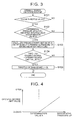
- FIG. 3 is a flowchart illustrating an opening degree limitation routine for setting the opening degree limit value OL of the throttle valve 6 so that the throttle valve 6 opens, as described above.
- the opening degree limitation routine is executed periodically, at interruptions every predetermined time, by the electronic control unit 21.
- step 101 (S101) of the routine the electronic control unit 21 determines whether the engine operation state is a state of closing the throttle valve 6 or not, specifically, determines whether the accelerator operation amount is "0" or not.
- the change in closing of the throttle valve 6 is limited according to the opening degree limit value OL, as described above, and, accordingly, the opening degree of the throttle valve 6 is equal to the opening degree limit value OL.
- Situations where the throttle valve 6 is to be closed include a situation wherein the throttle valve 6 closes accompanying for instance a reduction of the accelerator operation amount down to "0", by the driver, in order to decelerate the vehicle from a high load state (for instance, full load state) of the engine 1. In such a situation, the differential pressure ⁇ P of the first pressure P1 and the second pressure P2 (differential pressure before and after the throttle valve 6) increases readily.
- the electronic control unit 21 When the process of S101 yields a negative determination, the electronic control unit 21 temporarily terminates the opening degree limitation routine. When on the other hand the process of S101 yields an affirmative determination, the process proceeds to S102. As the process of S102, the electronic control unit 21 determines whether or not the differential pressure ⁇ P is equal to or greater than the determination value h. Regarding the determination value h that is used herein, a value established beforehand, for instance experimentally, may conceivably be used as an allowable upper limit of the differential pressure ⁇ P such that the throttle valve 6 does not deform when acted upon by a force derived from the differential pressure ⁇ P.
- the electronic control unit 21 terminates temporarily the opening degree limitation routine.
- the differential pressure ⁇ P is equal to or greater than the determination value h and S102 yields thus an affirmative determination
- the process proceeds to S103.
- the purpose of the process from S103 onwards is to correct the opening degree of the throttle valve 6 to increase the opening degree so that the throttle valve 6 opens even in an engine operation state in which the throttle valve 6 is to be closed.
- the electronic control unit 21 calculates the opening degree limit value OL on the basis of the differential pressure ⁇ P.
- the opening degree limit value OL thus calculated is variably set so as to increase gradually as the differential pressure ⁇ P increases with respect to the determination value h, as illustrated in FIG. 4 .
- the electronic control unit 21 determines whether or not the current throttle opening degree is a value further on the closing side (smaller value) than the above variably-set opening degree limit value OL. When a negative determination is obtained herein, the electronic control unit 21 temporarily terminates the opening degree limitation routine.
- the determination is affirmative, on the other hand, the process proceeds to S105.
- the electronic control unit 21 regulates the opening degree of the throttle valve 6 to the opening degree limit value OL having been set as described above.
- the opening degree limit value OL is variably set, in S103, to increase gradually as the differential pressure ⁇ P increases with respect to the determination value h, and the opening degree of the throttle valve 6 is restricted from becoming smaller than the opening degree limit value OL.
- the opening degree of the throttle valve 6 is corrected so as to become gradually larger as the differential pressure ⁇ P increases with respect to the determination value h.
- variable setting of the opening degree limit value OL is performed such that the throttle valve 6 does not come into contact with the inner wall of the intake passage 3 when a force derived from the differential pressure ⁇ P acts on the throttle valve 6, and such that the opening degree limit value OL takes on a value that is as small as possible (value such that the opening degree of the throttle valve 6 is near full closing).
- the opening degree of the throttle valve 6 is corrected so that the throttle valve 6 opens, when the differential pressure ⁇ P of the first pressure P1 and the second pressure P2 is equal to or greater than the determination value h, in an engine operation state in which the throttle valve 6 is to be closed.
- the opening degree of the throttle valve 6 is thus corrected so as to increase, even in a state in which the throttle valve 6 is to be closed, so that an increase in the differential pressure ⁇ P is suppressed as a result, i.e. there is suppressed an increase in the difference between the pressure in the intake passage 3 upstream of the throttle valve 6 (corresponding to the first pressure P1) and the pressure downstream of the valve 6 (corresponding to the second pressure P2).
- Excess air is undeniably supplied to the combustion chamber 2 of the engine 1 in a case where the opening degree of the throttle valve 6 is corrected so that the throttle valve 6 opens, when the differential pressure ⁇ P is equal to or greater than the determination value h, as described above.
- the opening degree of the throttle valve 6 is corrected so as to open only by a certain opening degree, irrespective of how large the differential pressure ⁇ P is with respect to the determination value h, the opening degree of the throttle valve 6 might therefore be uselessly large, which would give rise to significant excess air being supplied to the engine 1 through the intake passage 3, even though the engine operation state is a state in which the throttle valve 6 is to be closed.
- the opening degree of the throttle valve 6 is however corrected so as to increase gradually as the differential pressure ⁇ P becomes larger with respect to the determination value h; as a result, useless increase in the opening degree of the throttle valve 6 is suppressed to the utmost extent. It becomes therefore possible to suppress, to the utmost extent, supply of excess air into the combustion chamber 2 of the engine 1, through the intake passage 3, due to a useless increase in the opening degree of the throttle valve 6, in an engine operation state in which the throttle valve 6 is to be closed.
- the differential pressure ⁇ P increases readily at the time when the throttle valve 6 is being closed, from the high-load operation state of the engine 1. Accordingly, the valve 6 comes readily into contact with the inner wall of the intake passage 3 due to the occurrence of deformation of the throttle valve 6 through the action of a force derived from the differential pressure ⁇ P. Also in such a situation, the opening degree of the throttle valve 6 is corrected so as to increase when the differential pressure ⁇ P is equal to or greater than the determination value h, and as a result, it becomes possible to suppress deformation of the throttle valve 6 due to a force derived from the differential pressure ⁇ P that has increased, and to suppress also contact of the throttle valve 6 with the inner wall of the intake passage 3 due to such deformation.
- the opening degree of the throttle valve 6 is corrected so that the throttle valve 6 opens, when the differential pressure ⁇ P is equal to or greater than the determination value h, even in an engine operation state in which the valve 6 is to be closed. An increase in the differential pressure ⁇ P is suppressed thereby.
- a force derived from the differential pressure ⁇ P acts on the valve 6, contact of the valve 6 with the inner wall of the intake passage 3 due to deformation of the throttle valve 6 can be suppressed. It becomes also possible to suppress deformation of the shaft of the throttle valve 6, arising from contact of the valve 6 with the inner wall of the intake passage 3.
- the opening degree of the throttle valve 6 is corrected so as to become gradually larger as the differential pressure ⁇ P increases with respect to the determination value h. Accordingly, the opening degree of the throttle valve 6 does not increase uselessly. It becomes possible as a result to suppress supply of excess air into the combustion chamber 2 of the engine 1, through the intake passage 3, due to a useless increase in the opening degree of the throttle valve 6, in an engine operation state in which the throttle valve 6 is to be closed.
- the differential pressure ⁇ P increases readily at the time when the throttle valve 6 is being closed, from a high-load operation state of the engine 1, but also in such a situation, the opening degree of the throttle valve 6 is corrected so that the throttle valve 6 opens when the differential pressure ⁇ P is equal to or greater than the determination value h; as a result, it becomes possible to suppress an increase in the differential pressure ⁇ P. It becomes possible to suppress deformation of the throttle valve 6 due to a force derived from the differential pressure ⁇ P that has increased, and to suppress also contact of the throttle valve 6 with the inner wall of the intake passage 3 due to such deformation.
- a second embodiment of a throttle control device of an engine with supercharger will be explained next with reference to FIGS. 5 to 7 .
- a bypass passage 9 is connected, to the intake passage 3 of the engine 1 in this embodiment, at a portion, in the intake passage 3, upstream of the throttle valve 6 and downstream of the compressor wheel 4a, and a portion upstream of the compressor wheel 4a.
- the bypass passage 9 is provided with a bypass valve 10 that regulates the flow of air between the portion, in the intake passage 3, upstream of the throttle valve 6 and downstream of the compressor wheel 4a, and the portion upstream of the compressor wheel 4a.
- the regulation operation of the bypass valve 10 is controlled through the electronic control unit 21.
- the electronic control unit 21 sets normally the bypass passage 9 to a cutoff state, by closing the bypass valve 10. In this case, the portion, in the intake passage 3, upstream of the throttle valve 6 and downstream of the compressor wheel 4a, and the portion upstream of the compressor wheel 4a, do not communicate with each other via the bypass passage 9.
- the electronic control unit 21 opens the bypass valve 10 to bring thereby the bypass passage 9 to a communicating state.
- the portion, in the intake passage 3, upstream of the throttle valve 6 and downstream of the compressor wheel 4a, and the portion upstream of the compressor wheel 4a communicate with each other via the bypass passage 9.
- the electronic control unit 21 corrects the opening degree of the throttle valve 6 so that the throttle valve 6 opens, when the differential pressure ⁇ P is equal to or greater than the determination value h, also with the bypass passage 9 in a communicating state.
- FIG. 6 illustrates the change over time of accelerator operation amount, throttle opening degree, an opening and closing mode of the bypass valve 10, pressure in the intake system of the engine 1, and differential pressure before and after the throttle valve (between upstream and downstream of the throttle valve 6) in the intake system.
- the throttle valve 6 of the engine 1 which is in an open valve state, closes in response to the reduction of the accelerator operation amount, as denoted for instance by the solid line in the graph of throttle opening degree of FIG. 6 .
- the first pressure P1 solid line
- the second pressure P2 dashed line
- the differential pressure ⁇ P evolves in response thereto, as denoted by the graph of differential pressure before and after the throttle valve 6 of FIG. 6 .
- the electronic control unit 21 starts opening the bypass valve 10, as denoted by the graph of the bypass valve in FIG. 6 , from the point in time (timing T1a) at which the accelerator operation amount becomes "0".
- timing T1a the point in time at which the accelerator operation amount becomes "0".
- the opening degree of the throttle valve 6 need not be corrected so that the throttle valve 6 opens; accordingly, it becomes possible to suppress supply of excess air to the engine 1, through correction such that the opening degree of the throttle valve 6 increases.
- the differential pressure ⁇ P may in some instances become equal to or greater than the determination value h, without being suppressed to be smaller than the determination value h.
- the electronic control unit 21 corrects the opening degree of the throttle valve 6 so that the throttle valve 6 opens, through setting of a larger value as the opening degree limit value OL.
- the change in closing of the throttle valve 6 is limited according to the opening degree limit value OL, and the opening degree of the throttle valve 6 at the time when the throttle valve 6 is being closed is brought to a state in which the opening degree of the throttle valve 6 is corrected so that the throttle valve 6 opens, for instance as denoted by the two-dot chain line in the graph of the throttle opening degree in FIG. 6 .
- the differential pressure ⁇ P is reduced, to thereby suppress deformation of the throttle valve 6 through the action of a force derived from the differential pressure ⁇ P, and suppress contact of the throttle valve 6 with inner wall of the intake passage 3 due to such deformation.
- FIG. 7 is a flowchart illustrating an opening degree limitation routine of the present embodiment.
- the opening degree limitation routine is executed periodically, at interruptions every predetermined time, by the electronic control unit 21.
- the electronic control unit 21 determines whether or not the accelerator operation amount has been set to "0" from a high load state (for instance, full load state) of the engine 1, in other words, determines whether or not the engine operation state is an engine operation state in which the throttle valve is to be closed.
- a high load state for instance, full load state
- the electronic control unit 21 temporarily terminates the opening degree limitation routine, and when the process of S201 yields a negative determination, the process proceeds to S202.
- the electronic control unit 21 opens the bypass valve 10, to bring the bypass passage 9 to a communicating state.
- the electronic control unit 21 determines whether or not, under such situation, the differential pressure ⁇ P is equal to or greater than the determination value h. In a case where the differential pressure ⁇ P is smaller than the determination value h and S203 yields a negative determination, the electronic control unit 21 terminates temporarily the opening degree limitation routine. In a case where, on the other hand, the differential pressure ⁇ P is equal to or greater than the determination value h and S203 yields thus an affirmative determination, the process proceeds to S204.
- the process from S204 onwards corresponds to the process from S103 onwards in the opening degree limitation routine ( FIG. 3 ) of the first embodiment.
- the electronic control unit 21 calculates the opening degree limit value OL on the basis of the differential pressure ⁇ P, and as the process of subsequent S205, determines whether or not the current throttle opening degree is a value smaller than the opening degree limit value OL.
- S205 yields a negative determination
- the electronic control unit 21 temporarily terminates the opening degree limitation routine.
- the process proceeds to S206.
- the electronic control unit 21 regulates the opening degree of the throttle valve 6 to the opening degree limit value OL.
- the present embodiment explained in detail above elicits also the following effects.
- the electronic control unit 21 opens the bypass valve 10, to bring thereby the bypass passage 9 to a communicating state; as a result, the first pressure P1 is reduced, whereby an increase in the differential pressure ⁇ P is suppressed. Also in such a situation, the electronic control unit 21 corrects the opening degree of the throttle valve 6 so that the throttle valve 6 opens, when the differential pressure ⁇ P is equal to or greater than the determination value h.
- an increase in the differential pressure ⁇ P is suppressed by opening the bypass valve 10 without correcting, as much as possible, the opening degree of the throttle valve 6 so that the throttle valve 6 opens; accordingly, it becomes possible to suppress supply of excess air into the combustion chamber 2 of the engine 1 due to correction of the opening degree of the throttle valve 6 so that the throttle valve 6 opens. Further, it becomes possible to suppress deformation of the throttle valve 6, and to suppress contact of the throttle valve 6 with the inner wall of the intake passage 3 due to that deformation, through reduction of the differential pressure ⁇ P by correcting the opening degree of the throttle valve 6 so that the throttle valve 6 opens, when the differential pressure ⁇ P cannot be fully reduced just through opening of the bypass valve 10.
- the bypass valve 10 may be set to remain closed, or may be set to open, at the time when the throttle valve 6 is being closed, from a state in which the engine 1 is not in a high load state (when the accelerator operation amount becomes "0").
- the bypass valve 10 is kept closed, it is determined whether or not the differential pressure ⁇ P is equal to or greater than the determination value h, with the valve 10 in a closed valve state, and the opening degree of the throttle valve 6 is corrected so that the throttle valve 6 opens, on the basis of a determination to the effect that the differential pressure ⁇ P is equal to or greater than the determination value h.
- the opening degree limit value OL that limits closing of the throttle valve 6 is set to a value for which the opening degree of the throttle valve 6 is larger the larger the differential pressure ⁇ P is with respect to the determination value h, when the differential pressure ⁇ P is equal to or greater than the determination value h, so that, as a result, the opening degree of the throttle valve 6 at the time when the throttle valve 6 is being closed is corrected so as to increase gradually, but this configuration is not essential.
- the opening degree limit value OL may be modified to a fixed value, when the differential pressure ⁇ P is equal to or greater than the determination value h, whereby the opening degree of the throttle valve 6 is corrected such that the throttle valve 6 opens by a fixed opening degree.
- the opening degree of the throttle valve 6 may be set to be corrected so that the throttle valve 6 opens, on the basis of a determination to the effect that the differential pressure ⁇ P is equal to or greater than the determination value h, only at the time when the throttle valve 6 is being closed from a state in which the engine 1 is not in a full load state.
- the slope of the change in the value of the opening degree limit value OL with respect to the increase in the differential pressure ⁇ P can be modified, as appropriate, in accordance with the inner diameter (throttle bore diameter) of the portion of the intake passage 3 corresponding to the throttle valve 6.
- the slope is made smaller as the throttle bore diameter increases.
- the first pressure P1 is not limited to a value detected by the pressure sensor 22, and may be a value estimated on the basis of the engine operation state.
- the second pressure P2 as well is not limited to a value detected by the pressure sensor 26, and may be a value estimated on the basis of the engine operation state.
Landscapes
- Engineering & Computer Science (AREA)
- Chemical & Material Sciences (AREA)
- Combustion & Propulsion (AREA)
- Mechanical Engineering (AREA)
- General Engineering & Computer Science (AREA)
- Control Of Throttle Valves Provided In The Intake System Or In The Exhaust System (AREA)
- Supercharger (AREA)
Abstract
The invention relates to a control device for controlling an opening degree of a throttle valve (6) that is provided in an intake passage (3) of an engine (1) with a supercharger (4). When the throttle valve (6), which is in an open valve state, closes in response to an accelerator operation amount being reduced down to "0" by the driver in order to, for instance, decelerate a vehicle, an opening degree of the throttle valve (6) is corrected so that the throttle valve (6) opens, when a differential pressure (P) between pressure upstream of the throttle valve (6) and pressure downstream thereof in an intake passage (3) is equal to or greater than a determination value (h). An increase in the differential pressure (P) is suppressed through correction so that the throttle valve (6) opens. As a result, when a force derived from the differential pressure (P) acts on the throttle valve (6), a contact of the valve (6) with an inner wall of the intake passage (3) due to deformation of the throttle valve (6) can be suppressed.
Description
- The invention relates to a throttle control device of an engine with supercharger.
- In an engine with supercharger described in Japanese Patent Application Publication No.
8-144812 JP 8-144812 A - In the engine with supercharger, when the throttle valve in an open valve state closes, there increases a differential pressure between pressure upstream of the throttle valve and pressure downstream of the throttle valve in the intake passage, and a force derived from that differential pressure acts on the throttle valve, causing the throttle valve to deform, at the time when the throttle valve is being closed. As a result of that deformation of the throttle valve, the valve comes in contact with the inner wall of the intake passage. As a further concern, the shaft of the throttle valve may deform, due to contact between the throttle valve and the inner wall of the intake passage.
- The invention provides a throttle control device of an engine with supercharger such that contact of a throttle valve with an inner wall of an intake passage can be suppressed upon closing of the throttle valve which is in an open valve state.
- A control device according to an aspect of the invention, for controlling an opening degree of a throttle valve that is provided in an intake passage of an engine with supercharger, includes an electronic control unit. The electronic control unit is configured to correct an opening degree of the throttle valve so that the throttle valve opens, when an operation state of the engine in which the throttle valve is closed is established, and a differential pressure between pressure upstream of the throttle valve and pressure downstream of the throttle valve in the intake passage is equal to or greater than a determination value. Thus, the opening degree of the throttle valve is corrected through the electronic control unit such that the throttle valve opens, to thereby suppress an increase in the differential pressure between the pressure upstream of the throttle valve and the pressure downstream of the valve in the intake passage. Therefore, even when a force derived from the differential pressure acts on the throttle valve, deformation of the throttle valve can be accordingly suppressed, and it becomes possible to suppress also contact of the throttle valve with the inner wall in the intake passage caused by the above deformation.
- In the control device, the electronic control unit may be configured to correct the opening degree of the throttle valve such that the opening degree of the throttle valve becomes larger as the differential pressure increases from the determination value. In a case where the opening degree of the throttle valve is corrected so as to open only by a certain opening degree at the time when the throttle valve is being closed, irrespective of how large the differential pressure becomes with respect to the determination value, the opening degree of the throttle valve might be uselessly large, which would give rise to significant excess air being supplied to the engine through the intake passage. However, supply of excess air to the engine is suppressed by performing correction such that the opening degree of the throttle valve becomes larger as the differential pressure increases from the determination value, as described above.
- In the control device, the electronic control unit may be configured to correct the opening degree of the throttle valve so that the throttle valve opens, when the differential pressure is equal to or greater than the determination value at a time when the throttle valve is being closed, from a high-load operation state of the engine. The differential pressure increases readily at the time when the throttle valve is being closed, from the high-load operation state of the engine. Accordingly, the throttle valve comes readily into contact with the inner wall of the intake passage due to the occurrence of deformation of the valve through the action of a force derived from the differential pressure. In such a situation, the opening degree of the throttle valve is corrected so that the throttle valve opens when the differential pressure is equal to or greater than the determination value. Accordingly, it becomes possible to suppress deformation of the throttle valve due to a force derived from the differential pressure that has increased, and it becomes possible to suppress contact of the throttle valve with the inner wall in the intake passage caused by the above deformation.
- In the control device, the engine may include a bypass passage; the bypass passage may be provided at a portion, in the intake passage, upstream of the throttle valve that is positioned downstream of the supercharger; the bypass passage may connect a portion downstream of the supercharger and a portion upstream of the supercharger; the engine may include a bypass valve provided in the bypass passage; and the bypass valve may be configured to regulate flow of air in the bypass passage; the electronic control unit may be configured to open the bypass valve to cause the bypass passage to communicate, at the time when the throttle valve is being closed, from a high-load operation state of the engine; and the electronic control unit may correct the opening degree of the throttle valve so that the throttle valve opens, when the bypass passage is caused to communicate and the differential pressure is equal to or greater than the determination value. In this case, the electronic control unit opens the bypass valve, to bring the bypass passage to a communicating state, at the time when the throttle valve is being closed, from a high-load operation state of the engine, and corrects the opening degree of the throttle valve so that the throttle valve opens, when, in that state, the differential pressure is equal to or greater than the determination value.
- As described above, when the bypass valve is opened to bring the bypass passage to a communicating state, the portion in the intake passage upstream of the throttle valve and downstream of the supercharger, and the portion upstream of the supercharger, communicate with each other via the bypass valve; the pressure in the intake passage, upstream of the throttle valve, drops in response thereto, and the differential pressure is reduced. As a result, when the differential pressure can be curtailed to be smaller than the determination value, the opening degree of the throttle valve need not be corrected; accordingly it becomes possible to suppress supply of excess air to the engine by virtue of that correction. By contrast, in a case where the differential pressure is not smaller than the determination value even when the bypass passage is in a communicating state through opening of the bypass valve, the opening degree of the throttle valve is corrected so that the differential pressure is reduced. As a result, it is possible to suppress deformation of the throttle valve through the action of a force derived from the differential pressure, and also suppress contact of the throttle valve with the inner wall of the intake passage due to such deformation.
- It becomes therefore possible to suppress increases in the differential pressure by opening the bypass valve for bringing the bypass passage to a communicating state, without correcting, as much as possible, the opening degree of the throttle valve to a large opening degree, and it becomes possible to suppress supply of excess air to the engine through correction of the opening degree of the throttle valve so that the throttle valve opens. It becomes further possible to suppress deformation the throttle valve, and contact between the valve with the inner wall of the intake passage, due to such deformation, through correction of the opening degree of the throttle valve so that the latter opens, to reduce thereby the differential pressure, when the differential pressure cannot be fully reduced just through opening of the bypass valve for bringing the bypass passage to a communicating state.
- Features, advantages, and technical and industrial significance of exemplary embodiments of the invention will be described below with reference to the accompanying drawings, in which like numerals denote like elements, and wherein:
-
FIG. 1 is a schematic diagram illustrating a throttle control device of an engine with supercharger; -
FIG. 2 is a time chart illustrating the change over time of an accelerator operation amount, a throttle opening degree, pressure in an intake system of an engine, and differential pressure before and after a throttle valve (differential pressure between upstream and downstream of the throttle valve) in the intake system; -
FIG. 3 is a flowchart illustrating a procedure of setting an opening degree limit value so that a throttle valve opens; -
FIG. 4 is a graph illustrating the change of an opening degree limit value with respect to change in differential pressure before and after the throttle valve (differential pressure between upstream and downstream of the throttle valve) in an intake system of an engine; -
FIG. 5 is a schematic diagram illustrating a throttle control device of an engine with supercharger; -
FIG. 6 is a time chart illustrating the change over time of an accelerator operation amount, a throttle opening degree, an opening and closing mode of a bypass valve, pressure in an intake system of an engine, and differential pressure before and after the throttle valve (differential pressure between upstream and downstream of the throttle valve) in the intake system; and -
FIG. 7 is a flowchart illustrating a procedure of setting an opening degree limit value so that a throttle valve opens. - A first embodiment of a throttle control device of an engine with a supercharger will be explained next with reference to
FIGS. 1 to 4 . - An
engine 1 illustrated inFIG. 1 is installed in a vehicle such as an automobile. Acompressor wheel 4a of an exhaust turbine-type supercharger (turbocharger) 4 is provided in anintake passage 3 that is connected to acombustion chamber 2 of theengine 1. Further, athrottle valve 6 that regulates the amount of air that is supplied to thecombustion chamber 2 of theengine 1 is provided in theintake passage 3, downstream of thecompressor wheel 4a. - The amount of air that passes through the portion of the
intake passage 3 corresponding to thethrottle valve 6 varies with changes in the opening degree of the throttle valve 6 (throttle opening degree). The opening degree of thethrottle valve 6 is smallest, and the amount of air that passes through the portion of theintake passage 3 corresponding to thethrottle valve 6 becomes smallest, when thethrottle valve 6 is closed. - Air that has passed through the
intake passage 3 is supplied to thecombustion chamber 2 of theengine 1, and fuel is supplied into thecombustion chamber 2 by being injected, in an amount corresponding to the amount of air, throughfuel injection valves 7. Combustion of the fuel inside thecombustion chamber 2 drives theengine 1, and acrankshaft 20, being an output shaft of theengine 1, rotates as a result. - Exhaust gas after combustion of fuel inside the
combustion chamber 2 is fed to anexhaust passage 8 connected to thecombustion chamber 2. Aturbine wheel 4b of theturbocharger 4 is provided in theexhaust passage 8. When the exhaust gas that flows through theexhaust passage 8 passes through theturbine wheel 4b, theturbine wheel 4b rotates, and thecompressor wheel 4a as well rotates therewith. Air is thus supercharged into thecombustion chamber 2 through the rotation of thecompressor wheel 4a. The supercharging pressure in the in theengine 1 that is thus supercharged with by theturbocharger 4 rises with increasing flow rate of the air that is supplied to thecombustion chamber 2, and with increasing flow rate of the exhaust gas discharged out of thecombustion chamber 2, accompanying an increase in engine rotational speed. - The vehicle in which the
engine 1 is installed is also provided with anelectronic control unit 21 for controlling various items in theengine 1. Theelectronic control unit 21 is provided with, for instance, a central processing unit (CPU) that executes computation processes pertaining to the above various control items, a read only memory (ROM) in which programs and data necessary for control are stored, a random access memory (RAM) in which for instance computation results of the CPU are temporarily stored, and input-output ports for input and output of signals to/from the external devices. - Various sensors enumerated below are connected to the input port of the electronic control unit 21:
- a
throttle position sensor 23 that detects an opening degree of the throttle valve 6 (throttle opening degree); - an accelerator position sensor 24 that detects an operation amount of an accelerator pedal 19 (accelerator operation amount) that is operated by the driver of the vehicle;
- an
air flow meter 25 that detects the amount of air passing through theintake passage 3; - a
pressure sensor 22 that detects the pressure in theintake passage 3, upstream of thethrottle valve 6 and downstream of thecompressor wheel 4a; - a
pressure sensor 26 that detects the pressure in theintake passage 3 and is downstream of thethrottle valve 6; and - a crank
position sensor 27 for detecting the rotational speed of thecrankshaft 20 of theengine 1. - Driving circuits of various devices for controlling the operation of the
engine 1, for instance a driving circuit of thefuel injection valves 7 and a driving circuit of thethrottle valve 6, are connected to the output port of theelectronic control unit 21. - The
electronic control unit 21 determines, on the basis of detection signals inputted from the various sensors, the operation state of theengine 1, namely engine rotational speed and engine load (amount of air supplied to thecombustion chamber 2 per cycle of the engine). The engine rotational speed is obtained on the basis of a detection signal from thecrank position sensor 27. The engine load is calculated from the engine rotational speed and the amount of intake air of theengine 1 as obtained on the basis of detection signals of the accelerator position sensor 24, thethrottle position sensor 23, theair flow meter 25 and so forth. Theelectronic control unit 21 outputs instruction signals to the various driving circuits connected to the output port, in accordance with operation state of theengine 1, namely engine rotational speed and engine load. Fuel injection amount control, opening degree control of thethrottle valve 6 and the like in theengine 1 are thus executed via theelectronic control unit 21. Theelectronic control unit 21 that executes opening degree control of thethrottle valve 6 corrects the opening degree of thethrottle valve 6 so that thethrottle valve 6 opens at the time when thethrottle valve 6 is being closed. -
FIG. 2 illustrates the manner in which the accelerator operation amount, the throttle opening degree, the pressure in the intake system of theengine 1, and a differential pressure before and after the throttle valve (between upstream and downstream of the throttle valve) in the intake system change over time. - As illustrated in the graph of accelerator operation of
FIG. 2 , when the driver reduces the accelerator operation amount down to "0" from the point in time of timing t1 in order to, for instance, decelerate the vehicle, thethrottle valve 6 of theengine 1, which is in an open valve state, closes in response to the reduction of the accelerator operation amount, as denoted for instance by the solid line in the graph of throttle opening degree ofFIG. 2 . In theengine 1 having theturbocharger 4 assembled therewith, the pressure upstream of thethrottle valve 6 that is provided in theintake passage 3, and downstream of thecompressor wheel 4a, increases through the operation of theturbocharger 4. Accordingly, when thethrottle valve 6 closes (t1 onwards) as described above, a first pressure P1 denoted by a solid line in the graph of pressure inFIG. 2 , and being the pressure upstream of thethrottle valve 6, is maintained at a comparatively high value through the inertial action of the turbocharger 4 (compressor wheel 4a). By contrast, a second pressure P2 denoted by a dashed line in the graph of pressure ofFIG. 2 , and being the pressure in theintake passage 3 downstream of thethrottle valve 6, drops promptly when thethrottle valve 6 closes as described above. Accordingly, a differential pressure ΔP of the first pressure P1 and the second pressure P2 increases, as illustrated for timing t1 onwards in the graph of the differential pressure before and after the throttle valve ofFIG. 2 , and a concern arises that a force derived from the differential pressure ΔP may act on thethrottle valve 6, causing thethrottle valve 6 to deform. A further concern arises in that when thethrottle valve 6 and the inner wall of theintake passage 3 come into contact, due to such deformation of thethrottle valve 6, the shaft of thethrottle valve 6 as well may deform as a result of that contact. - In order to counter this problem, the
electronic control unit 21 corrects the opening degree of thethrottle valve 6, so that thethrottle valve 6 opens, when the differential pressure ΔP is equal to or greater than a determination value h (timing t2), in an engine operation state in which thethrottle valve 6 is to be closed. - The
electronic control unit 21 restricts the opening degree of thethrottle valve 6 from becoming smaller than an established opening degree limit value OL. Accordingly, closing of thethrottle valve 6 is restricted according to the opening degree limit value OL, when the accelerator operation amount is reduced to "0"; as a result, the opening degree of thethrottle valve 6 varies as denoted by the solid line in the graph of the throttle opening degree ofFIG. 2 , as described above. - The
electronic control unit 21 sets the opening degree limit value OL such that the opening degree of thethrottle valve 6 becomes yet larger when the differential pressure ΔP is equal to or greater than the determination value h (timing t2). By modifying thus the opening degree limit value OL such that the opening degree of thethrottle valve 6 becomes larger, closing of thethrottle valve 6 is thus restricted according to the opening degree limit value OL. A state is thus established in which the opening degree of thethrottle valve 6 is corrected so as to be yet larger, for instance as denoted by the two-dot chain line in the graph of throttle opening degree ofFIG. 2 . - As described above, the opening degree of the
throttle valve 6 is corrected so as to increase at the time when thethrottle valve 6 is being closed, to suppress as a result an increase of the differential pressure ΔP. Even when a force derived from the differential pressure ΔP acts on thethrottle valve 6, deformation of thethrottle valve 6 can thus be accordingly suppressed. It becomes also possible to suppress deformation of the shaft of thethrottle valve 6 arising from contact of thethrottle valve 6 with the inner wall of theintake passage 3, caused by the above deformation. -
FIG. 3 is a flowchart illustrating an opening degree limitation routine for setting the opening degree limit value OL of thethrottle valve 6 so that thethrottle valve 6 opens, as described above. The opening degree limitation routine is executed periodically, at interruptions every predetermined time, by theelectronic control unit 21. - As a process of step 101 (S101) of the routine, the
electronic control unit 21 determines whether the engine operation state is a state of closing thethrottle valve 6 or not, specifically, determines whether the accelerator operation amount is "0" or not. At this time, the change in closing of thethrottle valve 6 is limited according to the opening degree limit value OL, as described above, and, accordingly, the opening degree of thethrottle valve 6 is equal to the opening degree limit value OL. Situations where thethrottle valve 6 is to be closed include a situation wherein thethrottle valve 6 closes accompanying for instance a reduction of the accelerator operation amount down to "0", by the driver, in order to decelerate the vehicle from a high load state (for instance, full load state) of theengine 1. In such a situation, the differential pressure ΔP of the first pressure P1 and the second pressure P2 (differential pressure before and after the throttle valve 6) increases readily. - When the process of S101 yields a negative determination, the
electronic control unit 21 temporarily terminates the opening degree limitation routine. When on the other hand the process of S101 yields an affirmative determination, the process proceeds to S102. As the process of S102, theelectronic control unit 21 determines whether or not the differential pressure ΔP is equal to or greater than the determination value h. Regarding the determination value h that is used herein, a value established beforehand, for instance experimentally, may conceivably be used as an allowable upper limit of the differential pressure ΔP such that thethrottle valve 6 does not deform when acted upon by a force derived from the differential pressure ΔP. In a case where the differential pressure ΔP is smaller than the determination value h and S102 yields a negative determination, theelectronic control unit 21 terminates temporarily the opening degree limitation routine. In a case where, on the other hand, the differential pressure ΔP is equal to or greater than the determination value h and S102 yields thus an affirmative determination, the process proceeds to S103. The purpose of the process from S103 onwards is to correct the opening degree of thethrottle valve 6 to increase the opening degree so that thethrottle valve 6 opens even in an engine operation state in which thethrottle valve 6 is to be closed. - As the process of S103, the
electronic control unit 21 calculates the opening degree limit value OL on the basis of the differential pressure ΔP. The opening degree limit value OL thus calculated is variably set so as to increase gradually as the differential pressure ΔP increases with respect to the determination value h, as illustrated inFIG. 4 . As the process of S104, theelectronic control unit 21 determines whether or not the current throttle opening degree is a value further on the closing side (smaller value) than the above variably-set opening degree limit value OL. When a negative determination is obtained herein, theelectronic control unit 21 temporarily terminates the opening degree limitation routine. When the determination is affirmative, on the other hand, the process proceeds to S105. As the process of S105, theelectronic control unit 21 regulates the opening degree of thethrottle valve 6 to the opening degree limit value OL having been set as described above. - Therefore, the opening degree limit value OL is variably set, in S103, to increase gradually as the differential pressure ΔP increases with respect to the determination value h, and the opening degree of the
throttle valve 6 is restricted from becoming smaller than the opening degree limit value OL. The opening degree of thethrottle valve 6 is corrected so as to become gradually larger as the differential pressure ΔP increases with respect to the determination value h. Herein, variable setting of the opening degree limit value OL is performed such that thethrottle valve 6 does not come into contact with the inner wall of theintake passage 3 when a force derived from the differential pressure ΔP acts on thethrottle valve 6, and such that the opening degree limit value OL takes on a value that is as small as possible (value such that the opening degree of thethrottle valve 6 is near full closing). - The operation of the throttle control device of the engine with
supercharger 1 will be explained next. The opening degree of thethrottle valve 6 is corrected so that thethrottle valve 6 opens, when the differential pressure ΔP of the first pressure P1 and the second pressure P2 is equal to or greater than the determination value h, in an engine operation state in which thethrottle valve 6 is to be closed. The opening degree of thethrottle valve 6 is thus corrected so as to increase, even in a state in which thethrottle valve 6 is to be closed, so that an increase in the differential pressure ΔP is suppressed as a result, i.e. there is suppressed an increase in the difference between the pressure in theintake passage 3 upstream of the throttle valve 6 (corresponding to the first pressure P1) and the pressure downstream of the valve 6 (corresponding to the second pressure P2). Therefore, even when a force derived from the differential pressure ΔP acts on thethrottle valve 6, deformation of thethrottle valve 6 can be accordingly suppressed. It becomes also possible to suppress deformation of the shaft of thethrottle valve 6 arising from contact of thevalve 6 with the inner wall of theintake passage 3, caused by the above deformation. - Excess air is undeniably supplied to the
combustion chamber 2 of theengine 1 in a case where the opening degree of thethrottle valve 6 is corrected so that thethrottle valve 6 opens, when the differential pressure ΔP is equal to or greater than the determination value h, as described above. In a case where the opening degree of thethrottle valve 6 is corrected so as to open only by a certain opening degree, irrespective of how large the differential pressure ΔP is with respect to the determination value h, the opening degree of thethrottle valve 6 might therefore be uselessly large, which would give rise to significant excess air being supplied to theengine 1 through theintake passage 3, even though the engine operation state is a state in which thethrottle valve 6 is to be closed. The opening degree of thethrottle valve 6 is however corrected so as to increase gradually as the differential pressure ΔP becomes larger with respect to the determination value h; as a result, useless increase in the opening degree of thethrottle valve 6 is suppressed to the utmost extent. It becomes therefore possible to suppress, to the utmost extent, supply of excess air into thecombustion chamber 2 of theengine 1, through theintake passage 3, due to a useless increase in the opening degree of thethrottle valve 6, in an engine operation state in which thethrottle valve 6 is to be closed. - The differential pressure ΔP increases readily at the time when the
throttle valve 6 is being closed, from the high-load operation state of theengine 1. Accordingly, thevalve 6 comes readily into contact with the inner wall of theintake passage 3 due to the occurrence of deformation of thethrottle valve 6 through the action of a force derived from the differential pressure ΔP. Also in such a situation, the opening degree of thethrottle valve 6 is corrected so as to increase when the differential pressure ΔP is equal to or greater than the determination value h, and as a result, it becomes possible to suppress deformation of thethrottle valve 6 due to a force derived from the differential pressure ΔP that has increased, and to suppress also contact of thethrottle valve 6 with the inner wall of theintake passage 3 due to such deformation. - The present embodiment explained in detail above elicits the following effects. (1) The opening degree of the
throttle valve 6 is corrected so that thethrottle valve 6 opens, when the differential pressure ΔP is equal to or greater than the determination value h, even in an engine operation state in which thevalve 6 is to be closed. An increase in the differential pressure ΔP is suppressed thereby. As a result, when a force derived from the differential pressure ΔP acts on thevalve 6, contact of thevalve 6 with the inner wall of theintake passage 3 due to deformation of thethrottle valve 6 can be suppressed. It becomes also possible to suppress deformation of the shaft of thethrottle valve 6, arising from contact of thevalve 6 with the inner wall of theintake passage 3. - (2) The opening degree of the
throttle valve 6 is corrected so as to become gradually larger as the differential pressure ΔP increases with respect to the determination value h. Accordingly, the opening degree of thethrottle valve 6 does not increase uselessly. It becomes possible as a result to suppress supply of excess air into thecombustion chamber 2 of theengine 1, through theintake passage 3, due to a useless increase in the opening degree of thethrottle valve 6, in an engine operation state in which thethrottle valve 6 is to be closed. - (3) The differential pressure ΔP increases readily at the time when the
throttle valve 6 is being closed, from a high-load operation state of theengine 1, but also in such a situation, the opening degree of thethrottle valve 6 is corrected so that thethrottle valve 6 opens when the differential pressure ΔP is equal to or greater than the determination value h; as a result, it becomes possible to suppress an increase in the differential pressure ΔP. It becomes possible to suppress deformation of thethrottle valve 6 due to a force derived from the differential pressure ΔP that has increased, and to suppress also contact of thethrottle valve 6 with the inner wall of theintake passage 3 due to such deformation. - A second embodiment of a throttle control device of an engine with supercharger will be explained next with reference to
FIGS. 5 to 7 . - As illustrated in
FIG. 5 , abypass passage 9 is connected, to theintake passage 3 of theengine 1 in this embodiment, at a portion, in theintake passage 3, upstream of thethrottle valve 6 and downstream of thecompressor wheel 4a, and a portion upstream of thecompressor wheel 4a. Thebypass passage 9 is provided with abypass valve 10 that regulates the flow of air between the portion, in theintake passage 3, upstream of thethrottle valve 6 and downstream of thecompressor wheel 4a, and the portion upstream of thecompressor wheel 4a. - The regulation operation of the
bypass valve 10 is controlled through theelectronic control unit 21. Theelectronic control unit 21 sets normally thebypass passage 9 to a cutoff state, by closing thebypass valve 10. In this case, the portion, in theintake passage 3, upstream of thethrottle valve 6 and downstream of thecompressor wheel 4a, and the portion upstream of thecompressor wheel 4a, do not communicate with each other via thebypass passage 9. At the time when thethrottle valve 6 is being closed, from the high-load operation state of theengine 1, theelectronic control unit 21 opens thebypass valve 10 to bring thereby thebypass passage 9 to a communicating state. In this case, the portion, in theintake passage 3, upstream of thethrottle valve 6 and downstream of thecompressor wheel 4a, and the portion upstream of thecompressor wheel 4a, communicate with each other via thebypass passage 9. Theelectronic control unit 21 corrects the opening degree of thethrottle valve 6 so that thethrottle valve 6 opens, when the differential pressure ΔP is equal to or greater than the determination value h, also with thebypass passage 9 in a communicating state. -
FIG. 6 illustrates the change over time of accelerator operation amount, throttle opening degree, an opening and closing mode of thebypass valve 10, pressure in the intake system of theengine 1, and differential pressure before and after the throttle valve (between upstream and downstream of the throttle valve 6) in the intake system. - As illustrated in the graph of accelerator operation of
FIG. 6 , when the driver reduces the accelerator operation amount down to "0" from the point in time of timing t1 in order to, for instance, decelerate the vehicle, thethrottle valve 6 of theengine 1, which is in an open valve state, closes in response to the reduction of the accelerator operation amount, as denoted for instance by the solid line in the graph of throttle opening degree ofFIG. 6 . When thethrottle valve 6 closes thus, the first pressure P1 (solid line) and the second pressure P2 (dashed line) evolve as illustrated in the graph of pressure inFIG. 6 , and the differential pressure ΔP evolves in response thereto, as denoted by the graph of differential pressure before and after thethrottle valve 6 ofFIG. 6 . - At the time when the
throttle valve 6 is being closed from the high-load operation state of theengine 1, theelectronic control unit 21 starts opening thebypass valve 10, as denoted by the graph of the bypass valve inFIG. 6 , from the point in time (timing T1a) at which the accelerator operation amount becomes "0". Thus, an increase of the differential pressure ΔP can be suppressed when the first pressure P1 can be lowered promptly by bringing thebypass passage 9 to a communicating state through opening of thebypass valve 10. When the differential pressure ΔP can be curtailed to be smaller than the determination value h by opening thebypass valve 10, then the opening degree of thethrottle valve 6 need not be corrected so that thethrottle valve 6 opens; accordingly, it becomes possible to suppress supply of excess air to theengine 1, through correction such that the opening degree of thethrottle valve 6 increases. - In a case where, on the other hand, the first pressure P1 does not drop promptly due to a response delay in opening of the
bypass valve 10, even when thebypass valve 10 has started being opened at the timing t1a, the differential pressure ΔP may in some instances become equal to or greater than the determination value h, without being suppressed to be smaller than the determination value h. In such cases, theelectronic control unit 21 corrects the opening degree of thethrottle valve 6 so that thethrottle valve 6 opens, through setting of a larger value as the opening degree limit value OL. As a result, the change in closing of thethrottle valve 6 is limited according to the opening degree limit value OL, and the opening degree of thethrottle valve 6 at the time when thethrottle valve 6 is being closed is brought to a state in which the opening degree of thethrottle valve 6 is corrected so that thethrottle valve 6 opens, for instance as denoted by the two-dot chain line in the graph of the throttle opening degree inFIG. 6 . By correcting the opening degree of thethrottle valve 6 so that thethrottle valve 6 opens, the differential pressure ΔP is reduced, to thereby suppress deformation of thethrottle valve 6 through the action of a force derived from the differential pressure ΔP, and suppress contact of thethrottle valve 6 with inner wall of theintake passage 3 due to such deformation. - Therefore, it becomes possible to suppress an increase in the differential pressure ΔP by opening the
bypass valve 10 for bringing thebypass passage 9 to a communicating state, without correcting, as much as possible, the opening degree of thethrottle valve 6 at the time when thethrottle valve 6 is being closed, to a large opening degree. As a result, it becomes possible to suppress supply of excess air to thecombustion chamber 2 of theengine 1, through correction of the opening degree of thethrottle valve 6 so that thethrottle valve 6 opens. Further, it becomes possible to suppress deformation of thethrottle valve 6, and to suppress contact of thethrottle valve 6 with the inner wall of theintake passage 3 due to that deformation due to reduction of the differential pressure ΔP by correcting the opening degree of thethrottle valve 6 so that thethrottle valve 6 opens, when the differential pressure ΔP cannot be fully reduced just through opening of thebypass valve 10. -
FIG. 7 is a flowchart illustrating an opening degree limitation routine of the present embodiment. The opening degree limitation routine is executed periodically, at interruptions every predetermined time, by theelectronic control unit 21. - As the process of S201 in the routine, the
electronic control unit 21 determines whether or not the accelerator operation amount has been set to "0" from a high load state (for instance, full load state) of theengine 1, in other words, determines whether or not the engine operation state is an engine operation state in which the throttle valve is to be closed. When the process of S201 yields an affirmative determination, theelectronic control unit 21 temporarily terminates the opening degree limitation routine, and when the process of S201 yields a negative determination, the process proceeds to S202. As the process of S202, theelectronic control unit 21 opens thebypass valve 10, to bring thebypass passage 9 to a communicating state. - As the process of S203, the
electronic control unit 21 determines whether or not, under such situation, the differential pressure ΔP is equal to or greater than the determination value h. In a case where the differential pressure ΔP is smaller than the determination value h and S203 yields a negative determination, theelectronic control unit 21 terminates temporarily the opening degree limitation routine. In a case where, on the other hand, the differential pressure ΔP is equal to or greater than the determination value h and S203 yields thus an affirmative determination, the process proceeds to S204. The process from S204 onwards corresponds to the process from S103 onwards in the opening degree limitation routine (FIG. 3 ) of the first embodiment. - As the process of S204, the
electronic control unit 21 calculates the opening degree limit value OL on the basis of the differential pressure ΔP, and as the process of subsequent S205, determines whether or not the current throttle opening degree is a value smaller than the opening degree limit value OL. When S205 yields a negative determination, theelectronic control unit 21 temporarily terminates the opening degree limitation routine. When the determination is affirmative, on the other hand, the process proceeds to S206. As the process of S206, theelectronic control unit 21 regulates the opening degree of thethrottle valve 6 to the opening degree limit value OL. - In addition to effects (1) through (3) described for the first embodiment, the present embodiment explained in detail above elicits also the following effects. (4) At the time when the
throttle valve 6 is being closed, from a high-load operation state of the engine 1 (when the accelerator operation amount becomes "0"), theelectronic control unit 21 opens thebypass valve 10, to bring thereby thebypass passage 9 to a communicating state; as a result, the first pressure P1 is reduced, whereby an increase in the differential pressure ΔP is suppressed. Also in such a situation, theelectronic control unit 21 corrects the opening degree of thethrottle valve 6 so that thethrottle valve 6 opens, when the differential pressure ΔP is equal to or greater than the determination value h. Therefore, an increase in the differential pressure ΔP is suppressed by opening thebypass valve 10 without correcting, as much as possible, the opening degree of thethrottle valve 6 so that thethrottle valve 6 opens; accordingly, it becomes possible to suppress supply of excess air into thecombustion chamber 2 of theengine 1 due to correction of the opening degree of thethrottle valve 6 so that thethrottle valve 6 opens. Further, it becomes possible to suppress deformation of thethrottle valve 6, and to suppress contact of thethrottle valve 6 with the inner wall of theintake passage 3 due to that deformation, through reduction of the differential pressure ΔP by correcting the opening degree of thethrottle valve 6 so that thethrottle valve 6 opens, when the differential pressure ΔP cannot be fully reduced just through opening of thebypass valve 10. - The above embodiments can be modified for instance as described below. In the second embodiment, the
bypass valve 10 may be set to remain closed, or may be set to open, at the time when thethrottle valve 6 is being closed, from a state in which theengine 1 is not in a high load state (when the accelerator operation amount becomes "0"). In a case where thebypass valve 10 is kept closed, it is determined whether or not the differential pressure ΔP is equal to or greater than the determination value h, with thevalve 10 in a closed valve state, and the opening degree of thethrottle valve 6 is corrected so that thethrottle valve 6 opens, on the basis of a determination to the effect that the differential pressure ΔP is equal to or greater than the determination value h. In a case where thebypass valve 10 is opened, it is determined whether or not the differential pressure ΔP is equal to or greater than the determination value h, with thevalve 10 in an open valve state, and the opening degree of thethrottle valve 6 is corrected so that thethrottle valve 6 opens, on the basis of a determination to the effect that the differential pressure ΔP is equal to or greater than the determination value h. - In the first embodiment and the second embodiment, the opening degree limit value OL that limits closing of the
throttle valve 6 is set to a value for which the opening degree of thethrottle valve 6 is larger the larger the differential pressure ΔP is with respect to the determination value h, when the differential pressure ΔP is equal to or greater than the determination value h, so that, as a result, the opening degree of thethrottle valve 6 at the time when thethrottle valve 6 is being closed is corrected so as to increase gradually, but this configuration is not essential. Specifically, the opening degree limit value OL may be modified to a fixed value, when the differential pressure ΔP is equal to or greater than the determination value h, whereby the opening degree of thethrottle valve 6 is corrected such that thethrottle valve 6 opens by a fixed opening degree. - In the first embodiment, the opening degree of the
throttle valve 6 may be set to be corrected so that thethrottle valve 6 opens, on the basis of a determination to the effect that the differential pressure ΔP is equal to or greater than the determination value h, only at the time when thethrottle valve 6 is being closed from a state in which theengine 1 is not in a full load state. - Regarding the determination value h that is used herein, a value established beforehand, for instance experimentally, is conceivably used as a allowable upper limit of the differential pressure ΔP such that the
throttle valve 6 does not deform when acted upon by a force derived from the differential pressure ΔP, but such a value need not necessarily be used, and some other value may be resorted to. - In
FIG. 4 , the slope of the change in the value of the opening degree limit value OL with respect to the increase in the differential pressure ΔP can be modified, as appropriate, in accordance with the inner diameter (throttle bore diameter) of the portion of theintake passage 3 corresponding to thethrottle valve 6. Preferably, the slope is made smaller as the throttle bore diameter increases. - In the first embodiment and the second embodiment, the first pressure P1 is not limited to a value detected by the
pressure sensor 22, and may be a value estimated on the basis of the engine operation state. The second pressure P2 as well is not limited to a value detected by thepressure sensor 26, and may be a value estimated on the basis of the engine operation state.
Claims (4)
- A control device for controlling an opening degree of a throttle valve (6) that is provided in an intake passage (3) of an engine (1) with a supercharger (4), the control device comprising:an electronic control unit (21) configured to correct the opening degree of the throttle valve (6) so that the throttle valve (6) opens, when an operation state of the engine (1) in which the throttle valve (6) is closed is established, and a differential pressure between pressure upstream of the throttle valve (6) and pressure downstream of the throttle valve (6) in the intake passage (3) is equal to or greater than a determination value.
- The control device according to claim 1, wherein
the electronic control unit (21) is configured to correct the opening degree of the throttle valve (6) such that the opening degree of the throttle valve (6) becomes larger as the differential pressure increases from the determination value. - The control device according to claim 1 or 2, wherein
the electronic control unit (21) is configured to correct the opening degree of the throttle valve (6) so that the throttle valve (6) opens, when the differential pressure is equal to or greater than the determination value at a time when the throttle valve (6) is being closed, from a high-load operation state of the engine (1). - The control device according to any one of claims 1 to 3, wherein
the engine (1) includes a bypass passage (9),
the bypass passage (9) is provided at a portion in the intake passage (3) upstream of the throttle valve (6) that is positioned downstream of the supercharger (4),
the bypass passage (9) connects a portion downstream of the supercharger (4) and a portion upstream of the supercharger (4),
the engine (1) includes a bypass valve (10) provided in the bypass passage (9),
the bypass valve (10) is configured to regulate the flow of air in the bypass passage (9),
the electronic control unit (21) is configured to open the bypass valve (10) to cause the bypass passage (9) to communicate, at the time when the throttle valve (6) is being closed, from a high-load operation state of the engine (1), and
the electronic control unit (21) is configured to correct the opening degree of the throttle valve (6) so that the throttle valve (6) opens, when the bypass passage (9) is caused to communicate and the differential pressure is equal to or greater than the determination value.
Applications Claiming Priority (1)
| Application Number | Priority Date | Filing Date | Title |
|---|---|---|---|
| JP2014121486A JP2016000980A (en) | 2014-06-12 | 2014-06-12 | Throttle control device of engine with turbocharger |
Publications (1)
| Publication Number | Publication Date |
|---|---|
| EP2957751A1 true EP2957751A1 (en) | 2015-12-23 |
Family
ID=53476668
Family Applications (1)
| Application Number | Title | Priority Date | Filing Date |
|---|---|---|---|
| EP15171010.0A Withdrawn EP2957751A1 (en) | 2014-06-12 | 2015-06-08 | Throttle control device of engine with supercharger |
Country Status (4)
| Country | Link |
|---|---|
| US (1) | US20150361903A1 (en) |
| EP (1) | EP2957751A1 (en) |
| JP (1) | JP2016000980A (en) |
| CN (1) | CN105275621A (en) |
Cited By (1)
| Publication number | Priority date | Publication date | Assignee | Title |
|---|---|---|---|---|
| RU2770365C1 (en) * | 2018-12-26 | 2022-04-15 | Вэйчай Пауэр Ко., Лтд | Method and system for engine throttle control |
Families Citing this family (2)
| Publication number | Priority date | Publication date | Assignee | Title |
|---|---|---|---|---|
| JP6264329B2 (en) * | 2014-06-18 | 2018-01-24 | トヨタ自動車株式会社 | Vehicle drive control device |
| CN112664356A (en) * | 2020-12-03 | 2021-04-16 | 西安科美动力科技有限公司 | Gas engine branch air inlet control device and control method thereof |
Citations (6)
| Publication number | Priority date | Publication date | Assignee | Title |
|---|---|---|---|---|
| JPH08144812A (en) | 1994-11-18 | 1996-06-04 | Mitsubishi Motors Corp | Fuel supply control device for internal combustion engine with supercharger |
| DE19848368A1 (en) * | 1998-10-21 | 2000-04-27 | Bosch Gmbh Robert | Control method for automobile engine throttle element provides electrical movement into maximum opening position upon starting and/or stopping of engine |
| EP1026378A2 (en) * | 1999-02-02 | 2000-08-09 | Waukesha Engine Division, Dresser Equipment Group, Inc. | Turbocharger control management system and throttle reserve control |
| US20040250792A1 (en) * | 2003-06-12 | 2004-12-16 | Toyota Jidosha Kabushiki Kaisha | Control apparatus and control method for vehicle-mounted internal combustion engine |
| US20080047524A1 (en) * | 2006-08-25 | 2008-02-28 | Goro Tamai | Fuel-cut manifold absolute pressure control |
| US20090178655A1 (en) * | 2008-01-10 | 2009-07-16 | William Christopher Boley | Air induction system with recirculation loop |
Family Cites Families (5)
| Publication number | Priority date | Publication date | Assignee | Title |
|---|---|---|---|---|
| JP2003097298A (en) * | 2001-09-27 | 2003-04-03 | Nissan Motor Co Ltd | Control device for internal combustion engine with supercharger |
| JP2006152894A (en) * | 2004-11-29 | 2006-06-15 | Denso Corp | Throttle control device for internal combustion engine with supercharger |
| JP2006161609A (en) * | 2004-12-03 | 2006-06-22 | Toyota Motor Corp | Control device for an internal combustion engine with a supercharger |
| JP5056596B2 (en) * | 2008-06-04 | 2012-10-24 | 日産自動車株式会社 | Control device for internal combustion engine |
| JP2012067614A (en) * | 2010-09-21 | 2012-04-05 | Toyota Motor Corp | Device for controlling compressor outlet pressure |
-
2014
- 2014-06-12 JP JP2014121486A patent/JP2016000980A/en active Pending
-
2015
- 2015-05-20 US US14/717,649 patent/US20150361903A1/en not_active Abandoned
- 2015-06-08 EP EP15171010.0A patent/EP2957751A1/en not_active Withdrawn
- 2015-06-10 CN CN201510316221.4A patent/CN105275621A/en active Pending
Patent Citations (6)
| Publication number | Priority date | Publication date | Assignee | Title |
|---|---|---|---|---|
| JPH08144812A (en) | 1994-11-18 | 1996-06-04 | Mitsubishi Motors Corp | Fuel supply control device for internal combustion engine with supercharger |
| DE19848368A1 (en) * | 1998-10-21 | 2000-04-27 | Bosch Gmbh Robert | Control method for automobile engine throttle element provides electrical movement into maximum opening position upon starting and/or stopping of engine |
| EP1026378A2 (en) * | 1999-02-02 | 2000-08-09 | Waukesha Engine Division, Dresser Equipment Group, Inc. | Turbocharger control management system and throttle reserve control |
| US20040250792A1 (en) * | 2003-06-12 | 2004-12-16 | Toyota Jidosha Kabushiki Kaisha | Control apparatus and control method for vehicle-mounted internal combustion engine |
| US20080047524A1 (en) * | 2006-08-25 | 2008-02-28 | Goro Tamai | Fuel-cut manifold absolute pressure control |
| US20090178655A1 (en) * | 2008-01-10 | 2009-07-16 | William Christopher Boley | Air induction system with recirculation loop |
Cited By (1)
| Publication number | Priority date | Publication date | Assignee | Title |
|---|---|---|---|---|
| RU2770365C1 (en) * | 2018-12-26 | 2022-04-15 | Вэйчай Пауэр Ко., Лтд | Method and system for engine throttle control |
Also Published As
| Publication number | Publication date |
|---|---|
| US20150361903A1 (en) | 2015-12-17 |
| CN105275621A (en) | 2016-01-27 |
| JP2016000980A (en) | 2016-01-07 |
Similar Documents
| Publication | Publication Date | Title |
|---|---|---|
| US9915211B2 (en) | Abnormality diagnosis device and abnormality diagnosis method for supercharger | |
| JP5734478B1 (en) | Control device for an internal combustion engine with a supercharger | |
| US10041397B2 (en) | Electric waste gate valve system and method for controlling electric waste gate valve system | |
| JP5968504B1 (en) | Control device for an internal combustion engine with a supercharger | |
| CN105164393B (en) | The control device of engine with turbocharger and the method for controlling engine | |
| US10309298B2 (en) | Control device of an engine | |
| JP5826323B2 (en) | Throttle control device for internal combustion engine and throttle control method for internal combustion engine | |
| US20180038273A1 (en) | Control device for internal combustion engine | |
| EP2957751A1 (en) | Throttle control device of engine with supercharger | |
| KR20160061039A (en) | Turbocharger Control Duty Compensation Method | |
| WO2000058615A1 (en) | Device and method for controlling fuel injection amount of internal combustion engine with turbocharger | |
| US10711689B2 (en) | Control device of internal combustion engine | |
| JP2012154292A (en) | Device for control of internal combustion engine with supercharger | |
| US10578010B2 (en) | Control device for an internal combustion engine | |
| CN107476888B (en) | Method and system for controlling turbocharger of vehicle | |
| EP3078833A1 (en) | Control apparatus for internal combustion engine with supercharger and method for controlling the internal combustion engine | |
| JP5278696B2 (en) | Electric supercharger | |
| JP4827758B2 (en) | Fault diagnosis device for variable valve timing control device | |
| CN112855364B (en) | Control device for internal combustion engine | |
| JP6549759B2 (en) | EGR system of engine | |
| JP6398279B2 (en) | Control device for an internal combustion engine with a supercharger | |
| JP2018162758A (en) | Internal combustion engine failure determination device | |
| JP2016102426A (en) | Multistage supercharging system | |
| JP2018178753A (en) | Abnormality diagnosis device for internal combustion engine |
Legal Events
| Date | Code | Title | Description |
|---|---|---|---|
| PUAI | Public reference made under article 153(3) epc to a published international application that has entered the european phase |
Free format text: ORIGINAL CODE: 0009012 |
|
| 17P | Request for examination filed |
Effective date: 20150608 |
|
| AK | Designated contracting states |
Kind code of ref document: A1 Designated state(s): AL AT BE BG CH CY CZ DE DK EE ES FI FR GB GR HR HU IE IS IT LI LT LU LV MC MK MT NL NO PL PT RO RS SE SI SK SM TR |
|
| AX | Request for extension of the european patent |
Extension state: BA ME |
|
| STAA | Information on the status of an ep patent application or granted ep patent |
Free format text: STATUS: THE APPLICATION HAS BEEN WITHDRAWN |
|
| 18W | Application withdrawn |
Effective date: 20161116 |