EP2957743A1 - Vehicle cooling system - Google Patents
Vehicle cooling system Download PDFInfo
- Publication number
- EP2957743A1 EP2957743A1 EP15163732.9A EP15163732A EP2957743A1 EP 2957743 A1 EP2957743 A1 EP 2957743A1 EP 15163732 A EP15163732 A EP 15163732A EP 2957743 A1 EP2957743 A1 EP 2957743A1
- Authority
- EP
- European Patent Office
- Prior art keywords
- hydraulic oil
- cooler
- radiator
- cooling system
- upstream
- Prior art date
- Legal status (The legal status is an assumption and is not a legal conclusion. Google has not performed a legal analysis and makes no representation as to the accuracy of the status listed.)
- Withdrawn
Links
- 238000001816 cooling Methods 0.000 title claims abstract description 41
- 239000010720 hydraulic oil Substances 0.000 claims abstract description 42
- 238000011144 upstream manufacturing Methods 0.000 claims abstract description 25
- 239000000446 fuel Substances 0.000 claims abstract description 11
- 230000009977 dual effect Effects 0.000 description 2
- 238000010276 construction Methods 0.000 description 1
- 239000002826 coolant Substances 0.000 description 1
- 239000012530 fluid Substances 0.000 description 1
- 238000000034 method Methods 0.000 description 1
- 239000003921 oil Substances 0.000 description 1
Images
Classifications
-
- F—MECHANICAL ENGINEERING; LIGHTING; HEATING; WEAPONS; BLASTING
- F01—MACHINES OR ENGINES IN GENERAL; ENGINE PLANTS IN GENERAL; STEAM ENGINES
- F01P—COOLING OF MACHINES OR ENGINES IN GENERAL; COOLING OF INTERNAL-COMBUSTION ENGINES
- F01P11/00—Component parts, details, or accessories not provided for in, or of interest apart from, groups F01P1/00 - F01P9/00
- F01P11/08—Arrangements of lubricant coolers
-
- B—PERFORMING OPERATIONS; TRANSPORTING
- B60—VEHICLES IN GENERAL
- B60K—ARRANGEMENT OR MOUNTING OF PROPULSION UNITS OR OF TRANSMISSIONS IN VEHICLES; ARRANGEMENT OR MOUNTING OF PLURAL DIVERSE PRIME-MOVERS IN VEHICLES; AUXILIARY DRIVES FOR VEHICLES; INSTRUMENTATION OR DASHBOARDS FOR VEHICLES; ARRANGEMENTS IN CONNECTION WITH COOLING, AIR INTAKE, GAS EXHAUST OR FUEL SUPPLY OF PROPULSION UNITS IN VEHICLES
- B60K11/00—Arrangement in connection with cooling of propulsion units
- B60K11/02—Arrangement in connection with cooling of propulsion units with liquid cooling
- B60K11/04—Arrangement or mounting of radiators, radiator shutters, or radiator blinds
-
- F—MECHANICAL ENGINEERING; LIGHTING; HEATING; WEAPONS; BLASTING
- F01—MACHINES OR ENGINES IN GENERAL; ENGINE PLANTS IN GENERAL; STEAM ENGINES
- F01P—COOLING OF MACHINES OR ENGINES IN GENERAL; COOLING OF INTERNAL-COMBUSTION ENGINES
- F01P11/00—Component parts, details, or accessories not provided for in, or of interest apart from, groups F01P1/00 - F01P9/00
- F01P11/10—Guiding or ducting cooling-air, to, or from, liquid-to-air heat exchangers
-
- F—MECHANICAL ENGINEERING; LIGHTING; HEATING; WEAPONS; BLASTING
- F01—MACHINES OR ENGINES IN GENERAL; ENGINE PLANTS IN GENERAL; STEAM ENGINES
- F01P—COOLING OF MACHINES OR ENGINES IN GENERAL; COOLING OF INTERNAL-COMBUSTION ENGINES
- F01P3/00—Liquid cooling
-
- F—MECHANICAL ENGINEERING; LIGHTING; HEATING; WEAPONS; BLASTING
- F02—COMBUSTION ENGINES; HOT-GAS OR COMBUSTION-PRODUCT ENGINE PLANTS
- F02B—INTERNAL-COMBUSTION PISTON ENGINES; COMBUSTION ENGINES IN GENERAL
- F02B29/00—Engines characterised by provision for charging or scavenging not provided for in groups F02B25/00, F02B27/00 or F02B33/00 - F02B39/00; Details thereof
- F02B29/04—Cooling of air intake supply
- F02B29/0406—Layout of the intake air cooling or coolant circuit
- F02B29/0425—Air cooled heat exchangers
- F02B29/0431—Details or means to guide the ambient air to the heat exchanger, e.g. having a fan, flaps, a bypass or a special location in the engine compartment
-
- F—MECHANICAL ENGINEERING; LIGHTING; HEATING; WEAPONS; BLASTING
- F02—COMBUSTION ENGINES; HOT-GAS OR COMBUSTION-PRODUCT ENGINE PLANTS
- F02B—INTERNAL-COMBUSTION PISTON ENGINES; COMBUSTION ENGINES IN GENERAL
- F02B29/00—Engines characterised by provision for charging or scavenging not provided for in groups F02B25/00, F02B27/00 or F02B33/00 - F02B39/00; Details thereof
- F02B29/04—Cooling of air intake supply
- F02B29/045—Constructional details of the heat exchangers, e.g. pipes, plates, ribs, insulation, materials, or manufacturing and assembly
- F02B29/0475—Constructional details of the heat exchangers, e.g. pipes, plates, ribs, insulation, materials, or manufacturing and assembly the intake air cooler being combined with another device, e.g. heater, valve, compressor, filter or EGR cooler, or being assembled on a special engine location
-
- F—MECHANICAL ENGINEERING; LIGHTING; HEATING; WEAPONS; BLASTING
- F02—COMBUSTION ENGINES; HOT-GAS OR COMBUSTION-PRODUCT ENGINE PLANTS
- F02M—SUPPLYING COMBUSTION ENGINES IN GENERAL WITH COMBUSTIBLE MIXTURES OR CONSTITUENTS THEREOF
- F02M31/00—Apparatus for thermally treating combustion-air, fuel, or fuel-air mixture
- F02M31/20—Apparatus for thermally treating combustion-air, fuel, or fuel-air mixture for cooling
-
- B—PERFORMING OPERATIONS; TRANSPORTING
- B60—VEHICLES IN GENERAL
- B60Y—INDEXING SCHEME RELATING TO ASPECTS CROSS-CUTTING VEHICLE TECHNOLOGY
- B60Y2200/00—Type of vehicle
- B60Y2200/20—Off-Road Vehicles
- B60Y2200/22—Agricultural vehicles
- B60Y2200/221—Tractors
-
- F—MECHANICAL ENGINEERING; LIGHTING; HEATING; WEAPONS; BLASTING
- F01—MACHINES OR ENGINES IN GENERAL; ENGINE PLANTS IN GENERAL; STEAM ENGINES
- F01P—COOLING OF MACHINES OR ENGINES IN GENERAL; COOLING OF INTERNAL-COMBUSTION ENGINES
- F01P3/00—Liquid cooling
- F01P3/18—Arrangements or mounting of liquid-to-air heat-exchangers
- F01P2003/185—Arrangements or mounting of liquid-to-air heat-exchangers arranged in parallel
-
- F—MECHANICAL ENGINEERING; LIGHTING; HEATING; WEAPONS; BLASTING
- F01—MACHINES OR ENGINES IN GENERAL; ENGINE PLANTS IN GENERAL; STEAM ENGINES
- F01P—COOLING OF MACHINES OR ENGINES IN GENERAL; COOLING OF INTERNAL-COMBUSTION ENGINES
- F01P3/00—Liquid cooling
- F01P3/18—Arrangements or mounting of liquid-to-air heat-exchangers
- F01P2003/187—Arrangements or mounting of liquid-to-air heat-exchangers arranged in series
-
- F—MECHANICAL ENGINEERING; LIGHTING; HEATING; WEAPONS; BLASTING
- F01—MACHINES OR ENGINES IN GENERAL; ENGINE PLANTS IN GENERAL; STEAM ENGINES
- F01P—COOLING OF MACHINES OR ENGINES IN GENERAL; COOLING OF INTERNAL-COMBUSTION ENGINES
- F01P2060/00—Cooling circuits using auxiliaries
- F01P2060/02—Intercooler
-
- F—MECHANICAL ENGINEERING; LIGHTING; HEATING; WEAPONS; BLASTING
- F01—MACHINES OR ENGINES IN GENERAL; ENGINE PLANTS IN GENERAL; STEAM ENGINES
- F01P—COOLING OF MACHINES OR ENGINES IN GENERAL; COOLING OF INTERNAL-COMBUSTION ENGINES
- F01P2060/00—Cooling circuits using auxiliaries
- F01P2060/04—Lubricant cooler
-
- F—MECHANICAL ENGINEERING; LIGHTING; HEATING; WEAPONS; BLASTING
- F01—MACHINES OR ENGINES IN GENERAL; ENGINE PLANTS IN GENERAL; STEAM ENGINES
- F01P—COOLING OF MACHINES OR ENGINES IN GENERAL; COOLING OF INTERNAL-COMBUSTION ENGINES
- F01P2060/00—Cooling circuits using auxiliaries
- F01P2060/10—Fuel manifold
-
- F—MECHANICAL ENGINEERING; LIGHTING; HEATING; WEAPONS; BLASTING
- F01—MACHINES OR ENGINES IN GENERAL; ENGINE PLANTS IN GENERAL; STEAM ENGINES
- F01P—COOLING OF MACHINES OR ENGINES IN GENERAL; COOLING OF INTERNAL-COMBUSTION ENGINES
- F01P2060/00—Cooling circuits using auxiliaries
- F01P2060/14—Condenser
-
- Y—GENERAL TAGGING OF NEW TECHNOLOGICAL DEVELOPMENTS; GENERAL TAGGING OF CROSS-SECTIONAL TECHNOLOGIES SPANNING OVER SEVERAL SECTIONS OF THE IPC; TECHNICAL SUBJECTS COVERED BY FORMER USPC CROSS-REFERENCE ART COLLECTIONS [XRACs] AND DIGESTS
- Y02—TECHNOLOGIES OR APPLICATIONS FOR MITIGATION OR ADAPTATION AGAINST CLIMATE CHANGE
- Y02T—CLIMATE CHANGE MITIGATION TECHNOLOGIES RELATED TO TRANSPORTATION
- Y02T10/00—Road transport of goods or passengers
- Y02T10/10—Internal combustion engine [ICE] based vehicles
- Y02T10/12—Improving ICE efficiencies
Definitions
- the present invention refers to a vehicle cooling system.
- a typical tractor cooling package includes a fan, a radiator, a charge air cooler, a hydraulic oil cooler, a condenser, and a fuel cooler.
- a fan is used to pull air through the fluid filled heat exchangers. This fan is a major consumer of engine power. It is desired to provide an optimal front cooling package taking into account space, airflow, and fan power consumed for a variety of loads. It is also desired to provide a practically efficient front cooling package based upon the load cases most common to the actual users of the agricultural tractor.
- US 8 505 499 B2 discloses a cooling system for a construction machine.
- a radiator and a hydraulic oil cooler are arranged at a front surface side of a cooling fan in parallel with each other in a flow direction of the cooling air.
- An intercooler or charge air cooler and a condenser are arranged in parallel at a front surface side of the radiator and hydraulic oil cooler, and a fuel cooler is arranged at a front surface side of the condenser.
- the hydraulic oil cooler is a single pass oil cooler, rather than dual pass.
- an upper portion of the charge air cooler completely covers or obscures an upstream side of the hydraulic oil cooler.
- the hydraulic oil cooler receives air that is already warmed by the charge air cooler. This drives a substantial amount of heat into the hydraulic oil cooler and requires a larger hydraulic oil cooler, increases the overall size of the entire cooling system and requires more fan power.
- the vehicle cooling system comprises a fan, a radiator upstream of the fan and in a first air flow path, a fuel cooler upstream of the radiator in the first air flow path and adjacent to a side of the charge air cooler, and a hydraulic oil cooler adjacent to a side of the radiator and upstream of the fan and in a second air flow path which is parallel to the first air flow path.
- a vehicle cooling system 10 for an engine 11 includes a fan 12 and a radiator 14.
- the fan 12 pulls air along a first air flow path from left to right into and through the radiator 14.
- a charge air cooler 16 is upstream of the radiator 14 and is also in the first air flow path.
- a fuel cooler 18 may be upstream of the radiator 14 in the first air flow path and is below and adjacent to a bottom side 20 of the charge air cooler 16.
- a hydraulic oil cooler 22 is upstream of the fan 12.
- the hydraulic oil cooler 22 is a dual pass cooler which includes a first upstream hydraulic oil cooler unit 24 and a second downstream hydraulic oil cooler unit 26. Units 24 and 26 are connected together in series with respect to the flow of coolant (not shown). As best seen in Fig. 2 , a front or upstream portion of the first upstream hydraulic oil cooler unit 24 is positioned above and adjacent to a top side 28 of the charge air cooler 16, and a rear or downstream portion of the first upstream hydraulic oil cooler unit 24 is positioned above and adjacent to a top side 30 of the radiator 14. The second downstream hydraulic oil cooler unit 26 is completely positioned above and adjacent to the top side 30 of the radiator 14. Thus, the fan 12 pulls air along a second air flow path from left to right into and through the hydraulic oil cooler 22.
- the second air flow path is parallel to the first air flow path.
- the hydraulic oil cooler 22 has an upstream side 23 which is unobscured by any other cooling system components. As a result, the hydraulic oil cooler 22 is exposed to cooling air which has not previously passed through any other cooling unit.
- hydraulic oil first enters the second downstream hydraulic oil cooler unit 26 which is the second or downstream unit of hydraulic oil cooler 22 in the second air flow. Then, the hydraulic oil flows down to a tank and up into the first upstream hydraulic oil cooler unit 24 which is the first or upstream unit of hydraulic oil cooler 22 in the second air flow path. Alternatively, the hydraulic oil does not have to flow down then up - it can flow side to side, or up then down.
- the vehicle cooling system 10 also includes a condenser 32 which is positioned in the first air flow path between the fuel cooler 18 and the radiator 14.
- the condenser 26 is preferably positioned adjacent to the bottom side 20 of the charge air cooler 16.
- the hydraulic oil cooler 22 is placed so it is directly exposed to cooling air with no cooling unit in front of it and no cooling unit behind, so that the size of the hydraulic oil cooler 22 can be reduced. Placing the charge air cooler 16 in front of the radiator 14 caused the radiator 14 to have to be larger, but the overall cooling package size remained relatively compact and low in airflow.
- the condenser 32 and fuel cooler 18 can be placed either in front of the radiator 14 or in front of the charge air cooler 16. Due to the compact arrangement of the cooling units in combination with the use of a weighted usage profile, fan power consumption is reduced.
- a shuttered or louvered airflow path for the hydraulic oil cooler 22 would further reduce the fan power required as air would only be pulled through as much of the hydraulic oil cooler 22 as required to keep the hydraulic oil below a specified temperature. Less airflow means less power consumed by the fan 12 or equivalently, better fuel economy.
Landscapes
- Engineering & Computer Science (AREA)
- Chemical & Material Sciences (AREA)
- Combustion & Propulsion (AREA)
- Mechanical Engineering (AREA)
- General Engineering & Computer Science (AREA)
- Physics & Mathematics (AREA)
- Thermal Sciences (AREA)
- Transportation (AREA)
- Cooling, Air Intake And Gas Exhaust, And Fuel Tank Arrangements In Propulsion Units (AREA)
Abstract
Description
- The present invention refers to a vehicle cooling system.
- Operating a motor vehicle, such as an agricultural tractor, produces heat that must be rejected to the air through heat exchangers. A typical tractor cooling package includes a fan, a radiator, a charge air cooler, a hydraulic oil cooler, a condenser, and a fuel cooler. There have been many front cooling package designs all seeking to efficiently remove heat from the agricultural tractor. Typically, the fan is used to pull air through the fluid filled heat exchangers. This fan is a major consumer of engine power. It is desired to provide an optimal front cooling package taking into account space, airflow, and fan power consumed for a variety of loads. It is also desired to provide a practically efficient front cooling package based upon the load cases most common to the actual users of the agricultural tractor.
-
US 8 505 499 B2 discloses a cooling system for a construction machine. In this cooling system, a radiator and a hydraulic oil cooler are arranged at a front surface side of a cooling fan in parallel with each other in a flow direction of the cooling air. An intercooler or charge air cooler and a condenser are arranged in parallel at a front surface side of the radiator and hydraulic oil cooler, and a fuel cooler is arranged at a front surface side of the condenser. However, the hydraulic oil cooler is a single pass oil cooler, rather than dual pass. Also, an upper portion of the charge air cooler completely covers or obscures an upstream side of the hydraulic oil cooler. Thus, the hydraulic oil cooler receives air that is already warmed by the charge air cooler. This drives a substantial amount of heat into the hydraulic oil cooler and requires a larger hydraulic oil cooler, increases the overall size of the entire cooling system and requires more fan power. - It is desired to have a smaller hydraulic oil cooler which is exposed to cooling air which has not previously passed through any other cooling unit.
- This and other objects are achieved by the present invention, wherein a vehicle cooling system is provided. The vehicle cooling system comprises a fan, a radiator upstream of the fan and in a first air flow path, a fuel cooler upstream of the radiator in the first air flow path and adjacent to a side of the charge air cooler, and a hydraulic oil cooler adjacent to a side of the radiator and upstream of the fan and in a second air flow path which is parallel to the first air flow path.
- For a complete understanding of the objects, techniques, and structure of the invention reference should be made to the following detailed description and accompanying drawings:
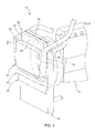
- Fig. 1
- is a perspective view of a vehicle cooling system embodying the invention, and
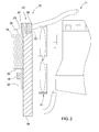
- Fig. 2
- is a left side view of the vehicle cooling system taken along line 2-2 in
Fig. 1 positioned in front of an engine. - Referring to
Figs. 1 and2 , avehicle cooling system 10 for anengine 11 includes afan 12 and aradiator 14. Thefan 12 pulls air along a first air flow path from left to right into and through theradiator 14. Acharge air cooler 16 is upstream of theradiator 14 and is also in the first air flow path. Afuel cooler 18 may be upstream of theradiator 14 in the first air flow path and is below and adjacent to abottom side 20 of thecharge air cooler 16. Ahydraulic oil cooler 22 is upstream of thefan 12. - The
hydraulic oil cooler 22 is a dual pass cooler which includes a first upstream hydraulicoil cooler unit 24 and a second downstream hydraulicoil cooler unit 26.Units Fig. 2 , a front or upstream portion of the first upstream hydraulicoil cooler unit 24 is positioned above and adjacent to atop side 28 of thecharge air cooler 16, and a rear or downstream portion of the first upstream hydraulicoil cooler unit 24 is positioned above and adjacent to atop side 30 of theradiator 14. The second downstream hydraulicoil cooler unit 26 is completely positioned above and adjacent to thetop side 30 of theradiator 14. Thus, thefan 12 pulls air along a second air flow path from left to right into and through thehydraulic oil cooler 22. The second air flow path is parallel to the first air flow path. Thehydraulic oil cooler 22 has anupstream side 23 which is unobscured by any other cooling system components. As a result, thehydraulic oil cooler 22 is exposed to cooling air which has not previously passed through any other cooling unit. - Preferably, hydraulic oil first enters the second downstream hydraulic
oil cooler unit 26 which is the second or downstream unit ofhydraulic oil cooler 22 in the second air flow. Then, the hydraulic oil flows down to a tank and up into the first upstream hydraulicoil cooler unit 24 which is the first or upstream unit ofhydraulic oil cooler 22 in the second air flow path. Alternatively, the hydraulic oil does not have to flow down then up - it can flow side to side, or up then down. - The
vehicle cooling system 10 also includes acondenser 32 which is positioned in the first air flow path between thefuel cooler 18 and theradiator 14. Thecondenser 26 is preferably positioned adjacent to thebottom side 20 of thecharge air cooler 16. - The
hydraulic oil cooler 22 is placed so it is directly exposed to cooling air with no cooling unit in front of it and no cooling unit behind, so that the size of thehydraulic oil cooler 22 can be reduced. Placing thecharge air cooler 16 in front of theradiator 14 caused theradiator 14 to have to be larger, but the overall cooling package size remained relatively compact and low in airflow. Thecondenser 32 andfuel cooler 18 can be placed either in front of theradiator 14 or in front of thecharge air cooler 16. Due to the compact arrangement of the cooling units in combination with the use of a weighted usage profile, fan power consumption is reduced. It is believed that a shuttered or louvered airflow path for thehydraulic oil cooler 22 would further reduce the fan power required as air would only be pulled through as much of thehydraulic oil cooler 22 as required to keep the hydraulic oil below a specified temperature. Less airflow means less power consumed by thefan 12 or equivalently, better fuel economy.
Claims (10)
- A vehicle cooling system, comprising a fan (12); a radiator (14) upstream of the fan (12) and in a first air flow path; a fuel cooler (18) upstream of the radiator (14) in the first air flow path and adjacent to a side of the charge air cooler (16); and a hydraulic oil cooler (22) adjacent to a side of the radiator (14) and upstream of the fan (12) and in a second air flow path which is parallel to the first air flow path.
- The vehicle cooling system according to claim 1, characterized by comprising a condenser (32) positioned in the first air flow path between the fuel cooler (18) and the radiator (14).
- The vehicle cooling system according to claim 2, characterized in that the condenser (32) is positioned adjacent to a side of the charge air cooler (16) between the radiator (14) and the fuel cooler (18).
- The vehicle cooling system according to claim 1 or 2, characterized in that the condenser (32) is positioned below a bottom side of the charge air cooler (16) and upstream of the radiator (14).
- The vehicle cooling system according to at least one of claims 1 to 4, characterized in that the hydraulic oil cooler (22) has an upstream side (23) which is unobscured by any other cooling system components.
- The vehicle cooling system according to at least one of claims 1 to 5, characterized in that the hydraulic oil cooler (22) comprises a first upstream hydraulic oil cooler unit (24) and a second downstream hydraulic oil cooler unit (26) connected together in series.
- The vehicle cooling system according to claim 6, characterized in that a portion of the first upstream hydraulic oil cooler unit (24) is positioned above a top side (28) of the charge air cooler (16), and the second downstream hydraulic oil cooler unit (26) is positioned above a top side (30) of the radiator (14).
- The vehicle cooling system according to at least one of claims 1 to 7, characterized in that at least a portion of the hydraulic oil cooler (22) is positioned above a top side (30) of the radiator (14).
- The vehicle cooling system according to at least one of claims 1 to 8, characterized in that the hydraulic oil cooler (22) is exposed to cooling air which has not previously passed through any other cooling unit.
- The vehicle cooling system according to at least one of claims 1 to 9, characterized by the charge air cooler (16) upstream of the radiator (14) in the first air flow path.
Applications Claiming Priority (1)
| Application Number | Priority Date | Filing Date | Title |
|---|---|---|---|
| US14/309,320 US9328652B2 (en) | 2014-06-19 | 2014-06-19 | Vehicle parallel cooling system |
Publications (1)
| Publication Number | Publication Date |
|---|---|
| EP2957743A1 true EP2957743A1 (en) | 2015-12-23 |
Family
ID=52997249
Family Applications (1)
| Application Number | Title | Priority Date | Filing Date |
|---|---|---|---|
| EP15163732.9A Withdrawn EP2957743A1 (en) | 2014-06-19 | 2015-04-15 | Vehicle cooling system |
Country Status (2)
| Country | Link |
|---|---|
| US (1) | US9328652B2 (en) |
| EP (1) | EP2957743A1 (en) |
Families Citing this family (20)
| Publication number | Priority date | Publication date | Assignee | Title |
|---|---|---|---|---|
| US10414266B1 (en) * | 2017-04-28 | 2019-09-17 | Oshkosh Defense, Llc | Vehicle cooling systems and methods |
| US9303715B2 (en) | 2013-03-10 | 2016-04-05 | Oshkosh Defense, Llc | Limiting system for a vehicle suspension component |
| US12491943B1 (en) | 2013-03-10 | 2025-12-09 | Oshkosh Defense, Llc | Systems and methods for a military vehicle |
| JP6415890B2 (en) * | 2014-08-04 | 2018-10-31 | 株式会社クボタ | Work vehicle |
| DE102014117007A1 (en) * | 2014-11-20 | 2016-05-25 | Valeo Klimasysteme Gmbh | Cooling module of a vehicle air conditioning system and assembly for cooling a motor vehicle engine with such a cooling module |
| US10300786B2 (en) * | 2014-12-19 | 2019-05-28 | Polaris Industries Inc. | Utility vehicle |
| CN118849684A (en) | 2015-05-15 | 2024-10-29 | 北极星工业有限公司 | Multi-purpose vehicles |
| KR102567146B1 (en) * | 2017-05-31 | 2023-08-18 | 한온시스템 주식회사 | Cooling module for vehicle |
| US10352229B2 (en) | 2017-12-18 | 2019-07-16 | Cnh Industrial America Llc | Cooling system for a work vehicle |
| US10550758B2 (en) | 2017-12-18 | 2020-02-04 | Cnh Industrial America Llc | Cooling system for a work vehicle |
| CN108661774A (en) * | 2018-06-21 | 2018-10-16 | 成都天地直方发动机有限公司 | A kind of high-power explosion-proof electronic controlled diesel vehicle radiator cooling device |
| USD892878S1 (en) * | 2019-02-28 | 2020-08-11 | Resource International Inc. | Transmission cooler for automotive applications |
| USD892877S1 (en) * | 2019-02-28 | 2020-08-11 | Resource International Inc. | Transmission cooler for automotive applications |
| CA3299418A1 (en) | 2019-04-30 | 2026-03-02 | Polaris Industries Inc. | Vehicle with removable final drive |
| US12187127B2 (en) | 2020-05-15 | 2025-01-07 | Polaris Industries Inc. | Off-road vehicle |
| US11691674B2 (en) | 2020-05-15 | 2023-07-04 | Polaris Industries Inc. | Off-road vehicle |
| KR102748884B1 (en) * | 2020-09-16 | 2025-01-03 | 삼성전자주식회사 | Semiconductor device including data storage material pattern |
| CN112539105A (en) * | 2020-12-15 | 2021-03-23 | 吉安市裕财机械工程有限公司 | Diesel generator's cooling system |
| CA3156559A1 (en) | 2021-05-05 | 2022-11-05 | Polaris Industries Inc. | Exhaust assembly for a utility vehicle |
| MX2023006716A (en) | 2022-06-13 | 2023-12-14 | Polaris Inc | POWER TRAIN FOR UTILITY VEHICLE. |
Citations (5)
| Publication number | Priority date | Publication date | Assignee | Title |
|---|---|---|---|---|
| WO2001014700A1 (en) * | 1999-08-23 | 2001-03-01 | Case Corporation | Cooling system for work vehicle |
| US20050252635A1 (en) * | 2004-05-14 | 2005-11-17 | Cnh America Llc | Tractor cooling system |
| EP1770255A1 (en) * | 2005-09-22 | 2007-04-04 | Deere & Company | Cooling device for a vehicle |
| WO2007077491A2 (en) * | 2005-12-30 | 2007-07-12 | Agco Sa | Tractor cooling installation |
| US8505499B2 (en) | 2009-10-16 | 2013-08-13 | Hitachi Construction Machinery Co., Ltd. | Cooling system for construction machine |
Family Cites Families (8)
| Publication number | Priority date | Publication date | Assignee | Title |
|---|---|---|---|---|
| DE102004024289A1 (en) | 2004-05-15 | 2005-12-15 | Deere & Company, Moline | Cooling system for a vehicle |
| US7325518B2 (en) | 2005-09-08 | 2008-02-05 | Deere & Company | Vehicle parallel cooling system |
| GB2437504B (en) | 2006-04-25 | 2009-12-02 | Agco Gmbh | Utility vehicles, in particular an agricultural tractor |
| US8379440B2 (en) * | 2009-05-01 | 2013-02-19 | The Royal Institution For The Advancement Of Learning/Mcgill University | Metallic-glass-based phase-change memory |
| US20110277973A1 (en) * | 2010-05-17 | 2011-11-17 | Foley Jason J | Cooling Circuit With Parallel Radiators |
| SE535564C2 (en) * | 2010-12-22 | 2012-09-25 | Scania Cv Ab | Cooling system in a vehicle |
| WO2012086519A1 (en) * | 2010-12-24 | 2012-06-28 | 株式会社小松製作所 | Construction vehicle |
| US20140116658A1 (en) * | 2012-10-30 | 2014-05-01 | Deere & Company | Vehicle cooling system |
-
2014
- 2014-06-19 US US14/309,320 patent/US9328652B2/en active Active
-
2015
- 2015-04-15 EP EP15163732.9A patent/EP2957743A1/en not_active Withdrawn
Patent Citations (5)
| Publication number | Priority date | Publication date | Assignee | Title |
|---|---|---|---|---|
| WO2001014700A1 (en) * | 1999-08-23 | 2001-03-01 | Case Corporation | Cooling system for work vehicle |
| US20050252635A1 (en) * | 2004-05-14 | 2005-11-17 | Cnh America Llc | Tractor cooling system |
| EP1770255A1 (en) * | 2005-09-22 | 2007-04-04 | Deere & Company | Cooling device for a vehicle |
| WO2007077491A2 (en) * | 2005-12-30 | 2007-07-12 | Agco Sa | Tractor cooling installation |
| US8505499B2 (en) | 2009-10-16 | 2013-08-13 | Hitachi Construction Machinery Co., Ltd. | Cooling system for construction machine |
Also Published As
| Publication number | Publication date |
|---|---|
| US9328652B2 (en) | 2016-05-03 |
| US20150369114A1 (en) | 2015-12-24 |
Similar Documents
| Publication | Publication Date | Title |
|---|---|---|
| US9328652B2 (en) | Vehicle parallel cooling system | |
| US11794547B2 (en) | Integrated thermal management module for vehicle | |
| DE112016005683T5 (en) | COOLER | |
| US20150129183A1 (en) | Heat exchanger having a cooler block and production method | |
| US20160109191A1 (en) | Cooling Module with Integral Surge Tank | |
| DE102010043978A1 (en) | Arrangement for cooling components of an HEV | |
| DE102010048853A1 (en) | Air conditioning system for a motor vehicle and method for operating an air conditioning system of a motor vehicle | |
| DE102014116084A1 (en) | Inverter and method for cooling an inverter | |
| CN204255153U (en) | Stacking plate type heat exchanger | |
| EP3224484B1 (en) | Cooling device for a hydraulic assembly and use of a cooling device | |
| DE102012206874B4 (en) | Cooling system for an electric vehicle and cooling method for an electrical component | |
| CN203906080U (en) | Combined radiator and combined radiating system | |
| DE102012105646A1 (en) | COOLER FOR VEHICLE | |
| CN107013311B (en) | Heat exchanger system | |
| DE102014221156A1 (en) | Motor vehicle with an aggregate space located inside the body | |
| US10018101B2 (en) | Cooling system and a method for its use | |
| DE102010063265A1 (en) | Intercooler | |
| US7926558B2 (en) | Cooler device | |
| JP6423999B2 (en) | aircraft | |
| WO2015055310A1 (en) | Internal combustion engine, in particular for a motor vehicle | |
| EP1770255B1 (en) | Cooling device for a vehicle | |
| DE112015002176T5 (en) | Cooling device of a hybrid vehicle | |
| KR101411413B1 (en) | Converter system including air cooling type single module cooler | |
| CN202889107U (en) | Heat-radiation structure of variable-frequency generator | |
| EP2058269A3 (en) | Industrial truck with a combustion engine and an electric generator |
Legal Events
| Date | Code | Title | Description |
|---|---|---|---|
| PUAI | Public reference made under article 153(3) epc to a published international application that has entered the european phase |
Free format text: ORIGINAL CODE: 0009012 |
|
| AK | Designated contracting states |
Kind code of ref document: A1 Designated state(s): AL AT BE BG CH CY CZ DE DK EE ES FI FR GB GR HR HU IE IS IT LI LT LU LV MC MK MT NL NO PL PT RO RS SE SI SK SM TR |
|
| AX | Request for extension of the european patent |
Extension state: BA ME |
|
| 17P | Request for examination filed |
Effective date: 20160623 |
|
| RBV | Designated contracting states (corrected) |
Designated state(s): AL AT BE BG CH CY CZ DE DK EE ES FI FR GB GR HR HU IE IS IT LI LT LU LV MC MK MT NL NO PL PT RO RS SE SI SK SM TR |
|
| 17Q | First examination report despatched |
Effective date: 20170130 |
|
| STAA | Information on the status of an ep patent application or granted ep patent |
Free format text: STATUS: THE APPLICATION IS DEEMED TO BE WITHDRAWN |
|
| 18D | Application deemed to be withdrawn |
Effective date: 20170610 |