EP2957477A1 - Stopper and method of manufacturing the same - Google Patents
Stopper and method of manufacturing the same Download PDFInfo
- Publication number
- EP2957477A1 EP2957477A1 EP15171795.6A EP15171795A EP2957477A1 EP 2957477 A1 EP2957477 A1 EP 2957477A1 EP 15171795 A EP15171795 A EP 15171795A EP 2957477 A1 EP2957477 A1 EP 2957477A1
- Authority
- EP
- European Patent Office
- Prior art keywords
- stopper
- inner body
- outer body
- shape
- rubber elastic
- Prior art date
- Legal status (The legal status is an assumption and is not a legal conclusion. Google has not performed a legal analysis and makes no representation as to the accuracy of the status listed.)
- Granted
Links
- 238000004519 manufacturing process Methods 0.000 title claims abstract description 9
- 230000007423 decrease Effects 0.000 claims description 5
- 238000000465 moulding Methods 0.000 description 15
- 238000000034 method Methods 0.000 description 8
- 239000000725 suspension Substances 0.000 description 5
- 238000004073 vulcanization Methods 0.000 description 5
- 239000004636 vulcanized rubber Substances 0.000 description 3
- 230000000694 effects Effects 0.000 description 2
- 238000010438 heat treatment Methods 0.000 description 2
- 239000000463 material Substances 0.000 description 1
- 238000012986 modification Methods 0.000 description 1
- 230000004048 modification Effects 0.000 description 1
- 238000003825 pressing Methods 0.000 description 1
Images

Classifications
-
- B—PERFORMING OPERATIONS; TRANSPORTING
- B61—RAILWAYS
- B61F—RAIL VEHICLE SUSPENSIONS, e.g. UNDERFRAMES, BOGIES OR ARRANGEMENTS OF WHEEL AXLES; RAIL VEHICLES FOR USE ON TRACKS OF DIFFERENT WIDTH; PREVENTING DERAILING OF RAIL VEHICLES; WHEEL GUARDS, OBSTRUCTION REMOVERS OR THE LIKE FOR RAIL VEHICLES
- B61F5/00—Constructional details of bogies; Connections between bogies and vehicle underframes; Arrangements or devices for adjusting or allowing self-adjustment of wheel axles or bogies when rounding curves
- B61F5/02—Arrangements permitting limited transverse relative movements between vehicle underframe or bolster and bogie; Connections between underframes and bogies
- B61F5/04—Bolster supports or mountings
- B61F5/10—Bolster supports or mountings incorporating fluid springs
Definitions
- the present invention relates to a block-like stopper made of a rubber elastic body.
- a stopper having a large size such as a stopper for a railway vehicle, that can be readily molded, and a method of manufacturing the same.
- Patent Literature 1 Japanese Patent Laid-Open No. 2012-86762
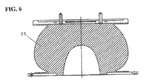
- a stopper 31 of this structure which is formed by a single vulcanized rubber block as shown in Figure 6 , is used in many railways in Europe and will be commonly used in the future.
- the stopper 31 made of a vulcanized rubber is molded by heating a mold charged with an unvulcanized rubber between upper and lower hot plates.
- the thickness of the stopper 31 increases, the difference in heat transfer between the surface of the stopper and the interior of the stopper becomes significant, and the properties of the finished stopper 31 are not uniform. The difference is particularly significant at the center part of the stopper 31 in the height direction, which is farthest from the hot plates.
- an object of the present invention is to provide a stopper having stable product characteristics that can be molded in a shorter time, and a method of manufacturing the same.
- the stopper in a stopper that is interposed between an air spring and a truck of a railway vehicle, the stopper comprises an outer body made of a rubber elastic body, and an inner body made of a rubber elastic body disposed in the outer body so as to be in contact with the outer body.
- the stopper made of a rubber elastic body is not a single block but is dividable into an inner body made of a rubber elastic body and an outer body made of a rubber elastic body that is in contact with the outer periphery of the inner body and covers the entire outer periphery of the inner body.
- the stopper is formed by separate members (the inner body and the outer body) made of a rubber elastic body. Therefore, compared with a stopper molded as a single block, the thickness of the product can be reduced, and the variation of the heat transfer with the part can be reduced. Therefore, the resilient characteristics and other product characteristics can be stabilized.
- each of the inner body and the outer body is smaller than the thickness of the whole of the stopper, heat is more efficiently transferred in the inner body and the outer body separately molded, so that a normal mold can be used for molding of the inner body and the outer body, instead of the jacket mold. Furthermore, if the inner body and the outer body are molded in parallel, the total molding time of the stopper can be reduced.
- the stopper for a railway vehicle is compressed in the direction of the central axis during use. Therefore, even if the stopper is configured to be dividable into the inner body and the outer body, the stopper serves in the same way as a stopper formed as an integral block of a rubber elastic body as far as the outer body is fixed in the state where no gap is formed between the inner body and the outer body, and has resilient characteristics close to those of the stopper formed as an integral block of a rubber elastic body.
- the inner body and the outer body can be formed at least so that the outer shape of the inner body and the inner shape of the outer body are substantially the same.
- substantially the same shape means that there may be a slight difference in shape but any gap that is formed between the outer body and the inner body fitted in the outer body does not have an effect on the resilient characteristics.
- the stopper for a railway vehicle With the stopper for a railway vehicle, a top part thereof is fixed to the air spring, and a bottom part is fixed to the truck. To this end, an upper plate for fixing the stopper to the air spring is fixed to the top part of the stopper, a lower plate for fixing the stopper to the truck is fixed to the bottom part of the stopper.
- the upper plate and the lower plate can be fixed to the outer body and do not have to be fixed to the inner body.
- the stopper in the state where the inner body is fitted in the outer body, the stopper can be attached to the railway vehicle by simply fixing the upper plate and lower plate fixed to the outer body to the air spring and the truck, respectively. That is, an assembly and attachment of the stopper can be smoothly and easily conducted.
- An outer shape of the inner body of the stopper can be slightly larger than an inner shape of the outer body.
- the stopper typically has a recess formed in the bottom part thereof, which provides cushioning properties.
- the recess is formed in the inner body. Therefore, even if the outer shape of the inner body with the recess formed therein is slightly larger than the inner shape of the outer body, the inner body can be deformed and forced into the outer body. This ensures that the outer surface of the inner body is pressed against and is in close contact with the inner surface of the outer body, so that resilient characteristics close to those of the single block-like stopper made of a rubber elastic body can be achieved.
- the outer shape of the inner body is configured to be substantially similar to the inner shape of the outer body.
- the expression “substantially similar” means the same as the expression “substantially the same shape” described above.
- the outer shape of the inner body is preferably 0.5 mm to 2.0 mm larger (in the outward direction) than the inner shape of the outer body and more preferably 0.5 mm to 1.0 mm larger than the inner shape of the outer body.
- the inner body can be formed so that an outer perimeter thereof gradually decreases as it goes from a bottom part thereof to a top part thereof. This ensures that the outer surface of the inner body is in contact with the inner surface of the outer body without air being trapped between the inner body and the outer body (or without any gap being formed between the inner body and the outer body).
- the inner body according to the present invention may be a single member or have a structure that is dividable into a plurality of parts.
- the present invention provides a method of manufacturing a stopper made of a rubber elastic body, in which the stopper comprises an outer body made of a rubber elastic body and an inner body that comprises one or two or more parts made of a rubber elastic body and is disposed in the inner surface of the outer body, and the parts of the inner body and the outer body are separately vulcanized and molded before the inner body is assembled into the outer body.
- the inner body and the outer body can be separately molded in different molds as described above, heat transfer is improved, and normal molds can be used for molding of the inner body and the outer body, instead of a jacket mold. Furthermore, the resilient characteristics and other product characteristics can be stabilized. Furthermore, if the inner body and the outer body are molded in parallel, the total molding time of the stopper can be reduced. According to the manufacturing method of the present invention, the stopper can be efficiently manufactured as described above.
- a stopper comprises an outer body made of a rubber elastic body and an inner body made of a rubber elastic body disposed in the outer body in contact with the outer body. Therefore, the product characteristics of the whole of the stopper can be stabilized by separately molding the outer body and the inner body. In addition, if the inner body and the outer body are molded in parallel, the total molding time of the whole of the stopper can be reduced.
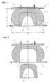
- Figure 1 is a vertical cross-sectional view of a stopper for a railway vehicle according to the present invention
- Figure 2 is an exploded cross-sectional view of the stopper for a railway vehicle according to the present invention.
- a stopper 1 is made of a rubber elastic body and has the shape of a thick-walled bowl or barrel turned upside down.
- the stopper 1 has a recess 2 opened toward the bottom of the stopper 1.
- An upper plate 3 having a disc-like shape is fixed to a top part of the stopper 1
- a lower plate 4 having a ring-like shape is fixed to the bottom part of the stopper 1.
- the bottom surface of the stopper 1 with the lower plate 4 fixed thereto has a ring-like shape, with a radially inner part of the ring being formed by the rubber elastic body, and a radially outer part of the ring being formed by the lower plate 4.
- the stopper 1 comprises an outer body 5 made of the rubber elastic body and an inner body 6 made of the rubber elastic body disposed in contact with the outer body 5.
- the outer body 5 and the inner body 6 are made of a rubber elastic body having the same material quality.
- the outer body 5 and the inner body 6 can be formed in a well-known conventional process. For example, as described in Japanese Patent Laid-Open No. 2012-86762 , vulcanization and molding of the rubber elastic body can be conducted by charging a mold with an unvulcanized rubber, closing the mold and then heating and pressing the mold between upper and lower hot plates.
- the outer body 5 and the inner body 6 can be separately molded in different molds.
- jacket molds do not have to be used, and normal molds can be used, since the finished products have thin walls.
- the rubber elastic body part of the bottom surface of the stopper 1 constitutes the bottom surface of the inner body 6. That is, the upper plate 3 and the lower plate 4 are fixed to the outer body 5, and no fixing fitting is attached to the inner body 6.
- the upper plate 3 and the lower plate 4 are integrally bonded to the outer body 5 by vulcanization when the outer body 5 is molded.
- the upper plate 3 and the lower plate 4 may be bonded to the outer body 5 after the outer body 5 is molded, or may be fixed to the outer body 5 with a fixture that is integrally molded with the outer body 5 when the outer body 5 is molded.
- the inner body 6 has the shape of a cylinder with a lid.
- the outer shape of the inner body 6 is a cylindrical shape.
- the outer body 5 has a recess 7 formed in a bottom part thereof, the recess 7 having the same diameter as the opening formed in the lower plate 4 at the center thereof.
- the inner shape of the recess 7 is a cylindrical shape that conforms to the shape of the inner body 6 so that the inner body 6 can be fitted into the recess 7.
- the shape of the inner body 6 may not be the shape of a cylinder with a lid and may be the shape of a polygonal cylinder with a lid.
- the stopper 1 is assembled by fitting the inner body 6 into the recess 7 of the outer body 5 through the opening in the lower plate 4.
- the outer body 5 and the inner body 6 are shaped so that no gap occurs between the outer body 5 and the inner body 6 in this assembly process.
- the outer shape of the inner body 6 is slightly larger than the inner shape of the outer body 5.
- the outer surface of the inner body 6 is pressed against and in close contact with the inner surface of the outer body 5, so that the stopper 1 has resilient characteristics close to those of a stopper formed by a single block of a rubber elastic body.
- irregularities may be formed on the outer surface of the inner body 6, and corresponding irregularities may be formed on the inner surface of the outer body 5. In that case, the contact area between the outer body 5 and the inner body 6 increases, and the stopper 1 can have resilient characteristics even closer to those of a stopper formed by a single block of a rubber elastic body.
- the irregularities formed on the outer surface of the inner body 6 may be an annular projection or annular recess formed along the perimeter of the outer surface of the inner body 6, for example. Furthermore, a series of annular projections and annular recesses may be formed on the outer surface of the inner body 6 so that the cross section of the outer surface of the inner body 6 is wave-like. In any of these cases, the outer body 5 has an inner shape that conforms to the outer shape of the inner body 6.
- the stopper 1 configured as described above is used as a component of a suspension device for a railway vehicle.
- the suspension device for a railway vehicle comprises an air spring 21 and the stopper 1 interposed between the air spring 21 and a truck (not shown).
- the stopper 1 is fixed to the truck via a support disc 22. More specifically, the lower plate 4 fixed to the stopper 1 is fixed to the support disc 22.
- the air spring 21 comprises an upper surface plate 23 attached to a body of the vehicle (not shown), a lower surface plate 24 disposed below the upper surface plate 23 on the side of the wheels, and a rubber diaphragm 25 disposed to bridge the upper surface plate 23 and the lower surface plate 24.
- the lower surface plate 24 is attached to the disc-shaped upper plate 3 fixed to the stopper 1.
- the lower plate 4 fixed to the stopper 1 is first fixed to the support disc 22 attached to the truck.
- the outer body 5 is fixed to the lower plate 4, while the inner body 6 is not fixed to the lower plate 4.
- the entire inner body 6 is covered and held by the outer body 5 once the lower plate 4 fixed to the outer body 5 is securely fixed to the support disc 22 with an appropriate fixture, such as a screw.
- an appropriate fixture such as a screw.
- the inner body 6 is inhibited from freely moving, and the outer body 5 and the inner body 6 serves as a single block-like stopper.
- the lower surface plate 24 of the air spring 21 is attached to the stopper 1 fixed to the truck, thereby completing assembly of the suspension device for a railway vehicle.
- the outer body 5 and the inner body 6 are formed with separate molds. Therefore, heat transfer is improved in both the outer body 5 and the inner body 6 in the separate molds, so that the product characteristics of the entire stopper can be stabilized. In addition, if the inner body and the outer body are molded in parallel, the total molding time of the stopper can be reduced.
- the outer shape of the inner body 6 according to this embodiment is slightly larger than the inner shape of the outer body 5. In this case, when the inner body 6 is fitted into the recess 7 of the outer body 5, any air trapped between the inner body 6 and the outer body 5 can inhibit the fitting of the inner body 6 into the recess 7 of the outer body 5.
- an air discharge groove 8 extending in the vertical direction can be formed in at least a cylindrical part of the outer surface of the inner body 6. At least one air discharge groove 8 needs to be formed, and a plurality of air discharge grooves 8 is preferably formed. In Figure 4 , three air discharge grooves 8 extending in the vertical direction are formed at regular intervals in the circumferential direction.
- the outer shape of the inner body 6 has been described as a cylindrical shape.
- the inner body 6 has to be forced into the outer body 5 while the inner body 6 is in contact with the outer body 5, and the fitting operation takes some effort because of the frictional force between the bodies.
- the frictional force increases, and the fitting operation takes additional effort.
- the inner body 6 may be shaped so that the outer perimeter gradually decreases as it goes from the bottom to the top. That is, the inner body 6 may be shaped so that the perimeter of the cross section perpendicular to the central axis CA decreases as it goes from the bottom to the top. In short, the inner body 6 may have a shape tapered from the bottom to the top. As a specific example, as shown in Figure 5 , the outer shape of the inner body 6 may be the shape of a truncated cone, instead of the cylindrical shape.
- the recess of the outer body 5 is shaped to conform to the outer shape of the inner body 6 shown in Figure 5 .
- This allows the inner body 6 to be smoothly and easily fitted into the outer body 5 to the depth of the recess 7.
- irregularities are formed on the outer surface of the inner body 6 and the inner surface of the outer body 5, the inner body 6 can be smoothly fitted into the outer body 5 while increasing the contact area between the outer body 5 and the inner body 6.
- the present invention is not limited to the embodiment described above, and various modifications can be made without departing from the spirit of the present invention.
- the inner body is formed as a single part in this embodiment, the present invention is not limited to this implementation, and the inner body may be dividable into a plurality of parts.
- the lid may be divided in the horizontal direction into two parts.
- the inner body is composed of a plurality of parts, the parts of the inner body and the outer body can be separately vulcanized and molded in different molds.
- the inner body and the outer body have been described as being made of the same rubber elastic body, the inner body and the outer body may be made of different rubber elastic bodies.
Landscapes
- Engineering & Computer Science (AREA)
- Mechanical Engineering (AREA)
- Fluid-Damping Devices (AREA)
- Vibration Dampers (AREA)
- Moulds For Moulding Plastics Or The Like (AREA)
Abstract
Description
- The present invention relates to a block-like stopper made of a rubber elastic body. In particular, it relates to a stopper having a large size, such as a stopper for a railway vehicle, that can be readily molded, and a method of manufacturing the same.
- As disclosed in Patent Literature 1 (Japanese Patent Laid-Open No.
2012-86762 stopper 31 of this structure, which is formed by a single vulcanized rubber block as shown inFigure 6 , is used in many railways in Europe and will be commonly used in the future. Thestopper 31 made of a vulcanized rubber is molded by heating a mold charged with an unvulcanized rubber between upper and lower hot plates. However, as the thickness of thestopper 31 increases, the difference in heat transfer between the surface of the stopper and the interior of the stopper becomes significant, and the properties of the finishedstopper 31 are not uniform. The difference is particularly significant at the center part of thestopper 31 in the height direction, which is farthest from the hot plates. - From the viewpoint of the resilient characteristics and durability of the stopper, it is desirable that the variation in properties of the stopper is small. A conventional process to achieve this is to mold the stopper for a long time at the lowest temperature allowable under the vulcanization condition. As an alternative, as disclosed in
Patent Literature 1 described above, there is a known process of using a jacket mold to control heat transfer in the stopper during molding of the stopper. - However, the process of vulcanization of the stopper at a low temperature for a long time leads to a decrease in the production rate of the stopper. The process of using a jacket mold described in
Patent Literature 1 requires a complicated mold structure. In addition, it is difficult to eliminate the variation of the heat transfer in the thickness direction of the stopper by using the jacket mold to adjust temperature. Thus, as the thickness of the stopper increases, the product characteristics (resilient characteristics) becomes less stable, and the molding (vulcanization) time cannot be substantially reduced. - In view of the problems described above, an object of the present invention is to provide a stopper having stable product characteristics that can be molded in a shorter time, and a method of manufacturing the same.
- To attain the object described above, according to the present invention, in a stopper that is interposed between an air spring and a truck of a railway vehicle, the stopper comprises an outer body made of a rubber elastic body, and an inner body made of a rubber elastic body disposed in the outer body so as to be in contact with the outer body.
- With the configuration described above, the stopper made of a rubber elastic body is not a single block but is dividable into an inner body made of a rubber elastic body and an outer body made of a rubber elastic body that is in contact with the outer periphery of the inner body and covers the entire outer periphery of the inner body. In other words, the stopper is formed by separate members (the inner body and the outer body) made of a rubber elastic body. Therefore, compared with a stopper molded as a single block, the thickness of the product can be reduced, and the variation of the heat transfer with the part can be reduced. Therefore, the resilient characteristics and other product characteristics can be stabilized.
- Since the thickness of each of the inner body and the outer body is smaller than the thickness of the whole of the stopper, heat is more efficiently transferred in the inner body and the outer body separately molded, so that a normal mold can be used for molding of the inner body and the outer body, instead of the jacket mold. Furthermore, if the inner body and the outer body are molded in parallel, the total molding time of the stopper can be reduced.
- The stopper for a railway vehicle is compressed in the direction of the central axis during use. Therefore, even if the stopper is configured to be dividable into the inner body and the outer body, the stopper serves in the same way as a stopper formed as an integral block of a rubber elastic body as far as the outer body is fixed in the state where no gap is formed between the inner body and the outer body, and has resilient characteristics close to those of the stopper formed as an integral block of a rubber elastic body.
- To dispose the inner body and the outer body in contact with each other, the inner body and the outer body can be formed at least so that the outer shape of the inner body and the inner shape of the outer body are substantially the same. The expression "substantially the same shape" means that there may be a slight difference in shape but any gap that is formed between the outer body and the inner body fitted in the outer body does not have an effect on the resilient characteristics.
- With the stopper for a railway vehicle, a top part thereof is fixed to the air spring, and a bottom part is fixed to the truck. To this end, an upper plate for fixing the stopper to the air spring is fixed to the top part of the stopper, a lower plate for fixing the stopper to the truck is fixed to the bottom part of the stopper. According to the present invention, the upper plate and the lower plate can be fixed to the outer body and do not have to be fixed to the inner body.
- With the configuration described above, in the state where the inner body is fitted in the outer body, the stopper can be attached to the railway vehicle by simply fixing the upper plate and lower plate fixed to the outer body to the air spring and the truck, respectively. That is, an assembly and attachment of the stopper can be smoothly and easily conducted.
- An outer shape of the inner body of the stopper can be slightly larger than an inner shape of the outer body. Specifically, the stopper typically has a recess formed in the bottom part thereof, which provides cushioning properties. The recess is formed in the inner body. Therefore, even if the outer shape of the inner body with the recess formed therein is slightly larger than the inner shape of the outer body, the inner body can be deformed and forced into the outer body. This ensures that the outer surface of the inner body is pressed against and is in close contact with the inner surface of the outer body, so that resilient characteristics close to those of the single block-like stopper made of a rubber elastic body can be achieved.
- Specifically, the outer shape of the inner body is configured to be substantially similar to the inner shape of the outer body. The expression "substantially similar" means the same as the expression "substantially the same shape" described above. With the central axes of the outer body and the inner body aligned with each other, the outer shape of the inner body is preferably 0.5 mm to 2.0 mm larger (in the outward direction) than the inner shape of the outer body and more preferably 0.5 mm to 1.0 mm larger than the inner shape of the outer body.
- The inner body can be formed so that an outer perimeter thereof gradually decreases as it goes from a bottom part thereof to a top part thereof. This ensures that the outer surface of the inner body is in contact with the inner surface of the outer body without air being trapped between the inner body and the outer body (or without any gap being formed between the inner body and the outer body).
- The inner body according to the present invention may be a single member or have a structure that is dividable into a plurality of parts.
- The present invention provides a method of manufacturing a stopper made of a rubber elastic body, in which the stopper comprises an outer body made of a rubber elastic body and an inner body that comprises one or two or more parts made of a rubber elastic body and is disposed in the inner surface of the outer body, and the parts of the inner body and the outer body are separately vulcanized and molded before the inner body is assembled into the outer body.
- According to the manufacturing method described above, since the inner body and the outer body can be separately molded in different molds as described above, heat transfer is improved, and normal molds can be used for molding of the inner body and the outer body, instead of a jacket mold. Furthermore, the resilient characteristics and other product characteristics can be stabilized. Furthermore, if the inner body and the outer body are molded in parallel, the total molding time of the stopper can be reduced. According to the manufacturing method of the present invention, the stopper can be efficiently manufactured as described above.
- According to the present invention, a stopper comprises an outer body made of a rubber elastic body and an inner body made of a rubber elastic body disposed in the outer body in contact with the outer body. Therefore, the product characteristics of the whole of the stopper can be stabilized by separately molding the outer body and the inner body. In addition, if the inner body and the outer body are molded in parallel, the total molding time of the whole of the stopper can be reduced.
-
-
Figure 1 is a vertical cross-sectional view of a stopper for a railway vehicle according to the present invention. -
Figure 2 is an exploded cross-sectional view of the stopper. -
Figure 3 is a cross-sectional view of a suspension device for a railway vehicle in which the stopper shown inFigure 1 is used as a component. -
Figure 4 is a front view showing a second form of an inner body. -
Figure 5 is a cross-sectional view showing a third form of the inner body. -
Figure 6 is a cross-sectional view showing a structure of a conventional stopper. - In the following, an embodiment of the present invention will be described with reference to the drawings by way of example only.
Figure 1 is a vertical cross-sectional view of a stopper for a railway vehicle according to the present invention, andFigure 2 is an exploded cross-sectional view of the stopper for a railway vehicle according to the present invention. - As shown in
Figure 1 , astopper 1 according to the present invention is made of a rubber elastic body and has the shape of a thick-walled bowl or barrel turned upside down. Thestopper 1 has arecess 2 opened toward the bottom of thestopper 1. Anupper plate 3 having a disc-like shape is fixed to a top part of thestopper 1, and alower plate 4 having a ring-like shape is fixed to the bottom part of thestopper 1. The bottom surface of thestopper 1 with thelower plate 4 fixed thereto has a ring-like shape, with a radially inner part of the ring being formed by the rubber elastic body, and a radially outer part of the ring being formed by thelower plate 4. - The
stopper 1 according to the present invention comprises anouter body 5 made of the rubber elastic body and aninner body 6 made of the rubber elastic body disposed in contact with theouter body 5. Theouter body 5 and theinner body 6 are made of a rubber elastic body having the same material quality. Theouter body 5 and theinner body 6 can be formed in a well-known conventional process. For example, as described in Japanese Patent Laid-Open No.2012-86762 - According to the present invention, the
outer body 5 and theinner body 6 can be separately molded in different molds. In this process, jacket molds do not have to be used, and normal molds can be used, since the finished products have thin walls. - The rubber elastic body part of the bottom surface of the
stopper 1 constitutes the bottom surface of theinner body 6. That is, theupper plate 3 and thelower plate 4 are fixed to theouter body 5, and no fixing fitting is attached to theinner body 6. According to this embodiment, theupper plate 3 and thelower plate 4 are integrally bonded to theouter body 5 by vulcanization when theouter body 5 is molded. Alternatively, theupper plate 3 and thelower plate 4 may be bonded to theouter body 5 after theouter body 5 is molded, or may be fixed to theouter body 5 with a fixture that is integrally molded with theouter body 5 when theouter body 5 is molded. - The
inner body 6 has the shape of a cylinder with a lid. In this case, the outer shape of theinner body 6 is a cylindrical shape. Theouter body 5 has arecess 7 formed in a bottom part thereof, therecess 7 having the same diameter as the opening formed in thelower plate 4 at the center thereof. The inner shape of therecess 7 is a cylindrical shape that conforms to the shape of theinner body 6 so that theinner body 6 can be fitted into therecess 7. The shape of theinner body 6 may not be the shape of a cylinder with a lid and may be the shape of a polygonal cylinder with a lid. - As shown in
Figure 2 , thestopper 1 is assembled by fitting theinner body 6 into therecess 7 of theouter body 5 through the opening in thelower plate 4. Theouter body 5 and theinner body 6 are shaped so that no gap occurs between theouter body 5 and theinner body 6 in this assembly process. According to this embodiment, the outer shape of theinner body 6 is slightly larger than the inner shape of theouter body 5. - With the configuration described above, the outer surface of the
inner body 6 is pressed against and in close contact with the inner surface of theouter body 5, so that thestopper 1 has resilient characteristics close to those of a stopper formed by a single block of a rubber elastic body. Furthermore, irregularities may be formed on the outer surface of theinner body 6, and corresponding irregularities may be formed on the inner surface of theouter body 5. In that case, the contact area between theouter body 5 and theinner body 6 increases, and thestopper 1 can have resilient characteristics even closer to those of a stopper formed by a single block of a rubber elastic body. - Specifically, the irregularities formed on the outer surface of the
inner body 6 may be an annular projection or annular recess formed along the perimeter of the outer surface of theinner body 6, for example. Furthermore, a series of annular projections and annular recesses may be formed on the outer surface of theinner body 6 so that the cross section of the outer surface of theinner body 6 is wave-like. In any of these cases, theouter body 5 has an inner shape that conforms to the outer shape of theinner body 6. - As shown in
Figure 3 , thestopper 1 configured as described above is used as a component of a suspension device for a railway vehicle. As shown in the drawing, the suspension device for a railway vehicle comprises anair spring 21 and thestopper 1 interposed between theair spring 21 and a truck (not shown). Thestopper 1 is fixed to the truck via asupport disc 22. More specifically, thelower plate 4 fixed to thestopper 1 is fixed to thesupport disc 22. - The
air spring 21 comprises anupper surface plate 23 attached to a body of the vehicle (not shown), alower surface plate 24 disposed below theupper surface plate 23 on the side of the wheels, and arubber diaphragm 25 disposed to bridge theupper surface plate 23 and thelower surface plate 24. Thelower surface plate 24 is attached to the disc-shapedupper plate 3 fixed to thestopper 1. - To assemble the suspension device for a railway vehicle configured as described above, the
lower plate 4 fixed to thestopper 1 is first fixed to thesupport disc 22 attached to the truck. In this process, theouter body 5 is fixed to thelower plate 4, while theinner body 6 is not fixed to thelower plate 4. - However, the entire
inner body 6 is covered and held by theouter body 5 once thelower plate 4 fixed to theouter body 5 is securely fixed to thesupport disc 22 with an appropriate fixture, such as a screw. As a result, theinner body 6 is inhibited from freely moving, and theouter body 5 and theinner body 6 serves as a single block-like stopper. After that, thelower surface plate 24 of theair spring 21 is attached to thestopper 1 fixed to the truck, thereby completing assembly of the suspension device for a railway vehicle. - As described in detail above, with the
stopper 1 according to the present invention, theouter body 5 and theinner body 6 are formed with separate molds. Therefore, heat transfer is improved in both theouter body 5 and theinner body 6 in the separate molds, so that the product characteristics of the entire stopper can be stabilized. In addition, if the inner body and the outer body are molded in parallel, the total molding time of the stopper can be reduced. - The effect of reduction of the molding time will be described with reference to a specific example. Referring to
Figure 1 , if a stopper having a maximum diameter D of 375 mm, a height H of 195 mm and a maximum wall thickness of 150 mm is formed as a single block, the required molding time is 6 hours at a temperature of 135°C. However, if a stopper that has the same size as described above but has the two-part structure composed of the outer body and the inner body is formed by separately molding the outer body and the inner body, the molding time in each of the molding conditions can be reduced to 4 hours at a temperature of 135°C, whereas resilient characteristics equal to those of the single block-like stopper described above can be achieved. - As described above, the outer shape of the
inner body 6 according to this embodiment is slightly larger than the inner shape of theouter body 5. In this case, when theinner body 6 is fitted into therecess 7 of theouter body 5, any air trapped between theinner body 6 and theouter body 5 can inhibit the fitting of theinner body 6 into therecess 7 of theouter body 5. - To avoid this, as shown in
Figure 4 , anair discharge groove 8 extending in the vertical direction can be formed in at least a cylindrical part of the outer surface of theinner body 6. At least oneair discharge groove 8 needs to be formed, and a plurality ofair discharge grooves 8 is preferably formed. InFigure 4 , threeair discharge grooves 8 extending in the vertical direction are formed at regular intervals in the circumferential direction. - In this embodiment, the outer shape of the
inner body 6 has been described as a cylindrical shape. However, to fit theinner body 6 into theouter body 5, theinner body 6 has to be forced into theouter body 5 while theinner body 6 is in contact with theouter body 5, and the fitting operation takes some effort because of the frictional force between the bodies. In particular, since the outer shape of theinner body 6 is slightly larger than the inner shape of theouter body 5, the frictional force increases, and the fitting operation takes additional effort. - To avoid this, the
inner body 6 may be shaped so that the outer perimeter gradually decreases as it goes from the bottom to the top. That is, theinner body 6 may be shaped so that the perimeter of the cross section perpendicular to the central axis CA decreases as it goes from the bottom to the top. In short, theinner body 6 may have a shape tapered from the bottom to the top. As a specific example, as shown inFigure 5 , the outer shape of theinner body 6 may be the shape of a truncated cone, instead of the cylindrical shape. - In this case, the recess of the
outer body 5 is shaped to conform to the outer shape of theinner body 6 shown inFigure 5 . This allows theinner body 6 to be smoothly and easily fitted into theouter body 5 to the depth of therecess 7. In particular, if irregularities are formed on the outer surface of theinner body 6 and the inner surface of theouter body 5, theinner body 6 can be smoothly fitted into theouter body 5 while increasing the contact area between theouter body 5 and theinner body 6. - The present invention is not limited to the embodiment described above, and various modifications can be made without departing from the spirit of the present invention. For example, although the inner body is formed as a single part in this embodiment, the present invention is not limited to this implementation, and the inner body may be dividable into a plurality of parts. For example, when the inner body has the shape of a cylinder with a lid, the lid may be divided in the horizontal direction into two parts. When the inner body is composed of a plurality of parts, the parts of the inner body and the outer body can be separately vulcanized and molded in different molds. Although the inner body and the outer body have been described as being made of the same rubber elastic body, the inner body and the outer body may be made of different rubber elastic bodies.
-
- 1
- stopper
- 2
- recess of stopper
- 3
- upper plate
- 4
- lower plate
- 5
- outer body
- 6
- inner body
- 7
- recess of outer body
- 8
- air discharge groove
- 21
- air spring
- 22
- support disc
- 23
- upper surface plate
- 24
- lower surface plate
- 25
- diaphragm
- D
- maximum diameter of stopper
- H
- height of stopper
- CA
- central axis
Claims (7)
- A stopper for interposition between an air spring and a truck of a railway vehicle, the stopper comprising:an outer body made of a rubber elastic body; andan inner body made of a rubber elastic body disposed in the outer body so as to be in contact with the outer body.
- The stopper according to claim 1, wherein an upper plate is fixed to a top part of the stopper, a lower plate is fixed to a bottom part of the stopper, and the upper plate and the lower plate are not fixed to the inner body but are fixed to the outer body.
- The stopper according to claim 1 or 2, wherein an outer shape of the inner body is slightly larger than an inner shape of the outer body.
- The stopper according to any one of claims 1 to 3, wherein an outer perimeter of the inner body gradually decreases as it goes from a bottom part thereof to a top part thereof.
- The stopper according to any one of claims 1 to 4, wherein the inner body has a structure that is dividable into a plurality of parts.
- The stopper according to any preceding claim, the stopper being interposed between an air spring and a truck of a railway vehicle.
- A method of manufacturing a stopper, wherein the stopper comprises an outer body made of a rubber elastic body and an inner body that comprises one or two or more parts made of a rubber elastic body and is disposed in the outer body so as to be in contact with the outer body, and the parts of the inner body and the outer body are separately vulcanized and molded before the inner body is assembled into the outer body.
Applications Claiming Priority (1)
| Application Number | Priority Date | Filing Date | Title |
|---|---|---|---|
| JP2014125875A JP6386261B2 (en) | 2014-06-19 | 2014-06-19 | Stopper and manufacturing method thereof |
Publications (2)
| Publication Number | Publication Date |
|---|---|
| EP2957477A1 true EP2957477A1 (en) | 2015-12-23 |
| EP2957477B1 EP2957477B1 (en) | 2019-09-25 |
Family
ID=53785395
Family Applications (1)
| Application Number | Title | Priority Date | Filing Date |
|---|---|---|---|
| EP15171795.6A Active EP2957477B1 (en) | 2014-06-19 | 2015-06-12 | A stopper, a railway vehicle and a method of manufacturing a stopper |
Country Status (3)
| Country | Link |
|---|---|
| EP (1) | EP2957477B1 (en) |
| JP (1) | JP6386261B2 (en) |
| CN (1) | CN105270427B (en) |
Families Citing this family (1)
| Publication number | Priority date | Publication date | Assignee | Title |
|---|---|---|---|---|
| CN107387641A (en) * | 2017-08-09 | 2017-11-24 | 安徽红桥金属制造有限公司 | A kind of air spring with rock-steady structure |
Citations (5)
| Publication number | Priority date | Publication date | Assignee | Title |
|---|---|---|---|---|
| JPS59191442U (en) * | 1983-06-08 | 1984-12-19 | トヨタ自動車株式会社 | Anti-vibration rubber |
| JPH07174177A (en) * | 1992-03-27 | 1995-07-11 | Bridgestone Corp | Large stroke air spring for railway |
| JP2003254378A (en) * | 2002-03-04 | 2003-09-10 | Bridgestone Corp | Air spring |
| JP2012086762A (en) | 2010-10-21 | 2012-05-10 | Toyo Tire & Rubber Co Ltd | Method of manufacturing stopper for railroad vehicle |
| WO2013181282A1 (en) * | 2012-05-29 | 2013-12-05 | Firestone Industrial Products Company, Llc | Fluid spring and rubber spring assembly |
Family Cites Families (7)
| Publication number | Priority date | Publication date | Assignee | Title |
|---|---|---|---|---|
| US3575403A (en) * | 1968-03-21 | 1971-04-20 | Pneumatiques Caoutchouc Mfg | Rubber-containing spring means |
| US4025063A (en) * | 1975-08-01 | 1977-05-24 | Midland-Ross Corporation | Cushioning pad |
| JPH0181305U (en) * | 1987-11-20 | 1989-05-31 | ||
| DE3833182A1 (en) * | 1988-09-30 | 1990-04-05 | Freudenberg Carl Fa | RUBBER BEARING |
| EP0554461B1 (en) * | 1991-08-23 | 1996-11-27 | Sumitomo Rubber Industries Limited | Laminated rubber support and method of designing the same |
| WO2009107679A1 (en) * | 2008-02-25 | 2009-09-03 | 株式会社ブリヂストン | Air spring device |
| JP2012137155A (en) * | 2010-12-27 | 2012-07-19 | Tokai Rubber Ind Ltd | Vibration damping device with stopper rubber part and method of manufacturing same |
-
2014
- 2014-06-19 JP JP2014125875A patent/JP6386261B2/en not_active Expired - Fee Related
-
2015
- 2015-05-08 CN CN201510232521.4A patent/CN105270427B/en not_active Expired - Fee Related
- 2015-06-12 EP EP15171795.6A patent/EP2957477B1/en active Active
Patent Citations (5)
| Publication number | Priority date | Publication date | Assignee | Title |
|---|---|---|---|---|
| JPS59191442U (en) * | 1983-06-08 | 1984-12-19 | トヨタ自動車株式会社 | Anti-vibration rubber |
| JPH07174177A (en) * | 1992-03-27 | 1995-07-11 | Bridgestone Corp | Large stroke air spring for railway |
| JP2003254378A (en) * | 2002-03-04 | 2003-09-10 | Bridgestone Corp | Air spring |
| JP2012086762A (en) | 2010-10-21 | 2012-05-10 | Toyo Tire & Rubber Co Ltd | Method of manufacturing stopper for railroad vehicle |
| WO2013181282A1 (en) * | 2012-05-29 | 2013-12-05 | Firestone Industrial Products Company, Llc | Fluid spring and rubber spring assembly |
Also Published As
| Publication number | Publication date |
|---|---|
| CN105270427B (en) | 2018-10-23 |
| JP6386261B2 (en) | 2018-09-05 |
| CN105270427A (en) | 2016-01-27 |
| EP2957477B1 (en) | 2019-09-25 |
| JP2016002945A (en) | 2016-01-12 |
Similar Documents
| Publication | Publication Date | Title |
|---|---|---|
| CA2560099C (en) | Closure with vents for venting during molding of a liner, method of forming a liner in a closure, and device for forming a liner in a closure | |
| US11090842B2 (en) | Valve insert and air venting valve | |
| EP2957477B1 (en) | A stopper, a railway vehicle and a method of manufacturing a stopper | |
| JP5607432B2 (en) | Rubber molding manufacturing method and transfer molding die | |
| CN109501342A (en) | The interior membrane module and tire-mold of tire-mold | |
| CN117404428A (en) | A series of rubber springs with small vertical stiffness and large longitudinal stiffness | |
| CN203488706U (en) | Explosion-proof valve | |
| CN104684717B (en) | The vulcanizing equipment with radially movable section for tire | |
| KR20160003625A (en) | Wax actuator with high cycle life | |
| US20110224005A1 (en) | Forging method, molding device for forgings, and tripod uniform motion universal joint | |
| JP6673665B2 (en) | Tire vulcanizing mold, tire vulcanizing apparatus and tire manufacturing method | |
| US20110104317A1 (en) | Mold for tire with floating mold back ring | |
| JP5509029B2 (en) | Method for manufacturing a railcar stopper | |
| JP6130761B2 (en) | Tire molding die and tire molding method | |
| US10315373B2 (en) | Self-locking mold comprising a shoulder spacer for molding and vulcanization of tires | |
| US10507625B2 (en) | Tire vulcanization mold | |
| US20190275757A1 (en) | Ventilation unit for a vulcanization mold of a vehicle pneumatic tire | |
| JP3217843U (en) | Tire vulcanization mold equipment | |
| KR20150105772A (en) | Vent plug for tire vulcanization mold | |
| KR20180067759A (en) | Solid type brake disc, manufacturing method of the same and manufacturing apparatus of the same | |
| KR200476473Y1 (en) | Apparatus for molding of contact lens | |
| JP7065538B2 (en) | Tire vulcanization mold equipment | |
| SK501302013U1 (en) | Container for segment vulcanization molds with spring mechanism | |
| SU870176A1 (en) | Injection mould for making rubber articles | |
| EP3991956A3 (en) | Improved tyre mould having modified sectored sidewall plates |
Legal Events
| Date | Code | Title | Description |
|---|---|---|---|
| PUAI | Public reference made under article 153(3) epc to a published international application that has entered the european phase |
Free format text: ORIGINAL CODE: 0009012 |
|
| 17P | Request for examination filed |
Effective date: 20150612 |
|
| AK | Designated contracting states |
Kind code of ref document: A1 Designated state(s): AL AT BE BG CH CY CZ DE DK EE ES FI FR GB GR HR HU IE IS IT LI LT LU LV MC MK MT NL NO PL PT RO RS SE SI SK SM TR |
|
| AX | Request for extension of the european patent |
Extension state: BA ME |
|
| RBV | Designated contracting states (corrected) |
Designated state(s): AL AT BE BG CH CY CZ DE DK EE ES FI FR GB GR HR HU IE IS IT LI LT LU LV MC MK MT NL NO PL PT RO RS SE SI SK SM TR |
|
| RAP1 | Party data changed (applicant data changed or rights of an application transferred) |
Owner name: TOYO TIRE & RUBBER CO., LTD. |
|
| GRAP | Despatch of communication of intention to grant a patent |
Free format text: ORIGINAL CODE: EPIDOSNIGR1 |
|
| STAA | Information on the status of an ep patent application or granted ep patent |
Free format text: STATUS: GRANT OF PATENT IS INTENDED |
|
| INTG | Intention to grant announced |
Effective date: 20180202 |
|
| GRAJ | Information related to disapproval of communication of intention to grant by the applicant or resumption of examination proceedings by the epo deleted |
Free format text: ORIGINAL CODE: EPIDOSDIGR1 |
|
| STAA | Information on the status of an ep patent application or granted ep patent |
Free format text: STATUS: REQUEST FOR EXAMINATION WAS MADE |
|
| INTC | Intention to grant announced (deleted) | ||
| GRAP | Despatch of communication of intention to grant a patent |
Free format text: ORIGINAL CODE: EPIDOSNIGR1 |
|
| STAA | Information on the status of an ep patent application or granted ep patent |
Free format text: STATUS: GRANT OF PATENT IS INTENDED |
|
| INTG | Intention to grant announced |
Effective date: 20180625 |
|
| GRAS | Grant fee paid |
Free format text: ORIGINAL CODE: EPIDOSNIGR3 |
|
| GRAJ | Information related to disapproval of communication of intention to grant by the applicant or resumption of examination proceedings by the epo deleted |
Free format text: ORIGINAL CODE: EPIDOSDIGR1 |
|
| GRAL | Information related to payment of fee for publishing/printing deleted |
Free format text: ORIGINAL CODE: EPIDOSDIGR3 |
|
| STAA | Information on the status of an ep patent application or granted ep patent |
Free format text: STATUS: REQUEST FOR EXAMINATION WAS MADE |
|
| GRAP | Despatch of communication of intention to grant a patent |
Free format text: ORIGINAL CODE: EPIDOSNIGR1 |
|
| STAA | Information on the status of an ep patent application or granted ep patent |
Free format text: STATUS: GRANT OF PATENT IS INTENDED |
|
| INTC | Intention to grant announced (deleted) | ||
| INTG | Intention to grant announced |
Effective date: 20181122 |
|
| GRAJ | Information related to disapproval of communication of intention to grant by the applicant or resumption of examination proceedings by the epo deleted |
Free format text: ORIGINAL CODE: EPIDOSDIGR1 |
|
| GRAL | Information related to payment of fee for publishing/printing deleted |
Free format text: ORIGINAL CODE: EPIDOSDIGR3 |
|
| STAA | Information on the status of an ep patent application or granted ep patent |
Free format text: STATUS: REQUEST FOR EXAMINATION WAS MADE |
|
| GRAP | Despatch of communication of intention to grant a patent |
Free format text: ORIGINAL CODE: EPIDOSNIGR1 |
|
| STAA | Information on the status of an ep patent application or granted ep patent |
Free format text: STATUS: GRANT OF PATENT IS INTENDED |
|
| INTC | Intention to grant announced (deleted) | ||
| INTG | Intention to grant announced |
Effective date: 20190411 |
|
| RAP1 | Party data changed (applicant data changed or rights of an application transferred) |
Owner name: TOYO TIRE CORPORATION |
|
| GRAA | (expected) grant |
Free format text: ORIGINAL CODE: 0009210 |
|
| STAA | Information on the status of an ep patent application or granted ep patent |
Free format text: STATUS: THE PATENT HAS BEEN GRANTED |
|
| AK | Designated contracting states |
Kind code of ref document: B1 Designated state(s): AL AT BE BG CH CY CZ DE DK EE ES FI FR GB GR HR HU IE IS IT LI LT LU LV MC MK MT NL NO PL PT RO RS SE SI SK SM TR |
|
| REG | Reference to a national code |
Ref country code: GB Ref legal event code: FG4D |
|
| REG | Reference to a national code |
Ref country code: CH Ref legal event code: EP |
|
| REG | Reference to a national code |
Ref country code: DE Ref legal event code: R096 Ref document number: 602015038552 Country of ref document: DE |
|
| REG | Reference to a national code |
Ref country code: AT Ref legal event code: REF Ref document number: 1183545 Country of ref document: AT Kind code of ref document: T Effective date: 20191015 |
|
| REG | Reference to a national code |
Ref country code: IE Ref legal event code: FG4D |
|
| REG | Reference to a national code |
Ref country code: NL Ref legal event code: MP Effective date: 20190925 |
|
| PG25 | Lapsed in a contracting state [announced via postgrant information from national office to epo] |
Ref country code: BG Free format text: LAPSE BECAUSE OF FAILURE TO SUBMIT A TRANSLATION OF THE DESCRIPTION OR TO PAY THE FEE WITHIN THE PRESCRIBED TIME-LIMIT Effective date: 20191225 Ref country code: NO Free format text: LAPSE BECAUSE OF FAILURE TO SUBMIT A TRANSLATION OF THE DESCRIPTION OR TO PAY THE FEE WITHIN THE PRESCRIBED TIME-LIMIT Effective date: 20191225 Ref country code: FI Free format text: LAPSE BECAUSE OF FAILURE TO SUBMIT A TRANSLATION OF THE DESCRIPTION OR TO PAY THE FEE WITHIN THE PRESCRIBED TIME-LIMIT Effective date: 20190925 Ref country code: LT Free format text: LAPSE BECAUSE OF FAILURE TO SUBMIT A TRANSLATION OF THE DESCRIPTION OR TO PAY THE FEE WITHIN THE PRESCRIBED TIME-LIMIT Effective date: 20190925 Ref country code: SE Free format text: LAPSE BECAUSE OF FAILURE TO SUBMIT A TRANSLATION OF THE DESCRIPTION OR TO PAY THE FEE WITHIN THE PRESCRIBED TIME-LIMIT Effective date: 20190925 Ref country code: HR Free format text: LAPSE BECAUSE OF FAILURE TO SUBMIT A TRANSLATION OF THE DESCRIPTION OR TO PAY THE FEE WITHIN THE PRESCRIBED TIME-LIMIT Effective date: 20190925 |
|
| REG | Reference to a national code |
Ref country code: LT Ref legal event code: MG4D |
|
| PG25 | Lapsed in a contracting state [announced via postgrant information from national office to epo] |
Ref country code: LV Free format text: LAPSE BECAUSE OF FAILURE TO SUBMIT A TRANSLATION OF THE DESCRIPTION OR TO PAY THE FEE WITHIN THE PRESCRIBED TIME-LIMIT Effective date: 20190925 Ref country code: RS Free format text: LAPSE BECAUSE OF FAILURE TO SUBMIT A TRANSLATION OF THE DESCRIPTION OR TO PAY THE FEE WITHIN THE PRESCRIBED TIME-LIMIT Effective date: 20190925 Ref country code: GR Free format text: LAPSE BECAUSE OF FAILURE TO SUBMIT A TRANSLATION OF THE DESCRIPTION OR TO PAY THE FEE WITHIN THE PRESCRIBED TIME-LIMIT Effective date: 20191226 |
|
| REG | Reference to a national code |
Ref country code: AT Ref legal event code: MK05 Ref document number: 1183545 Country of ref document: AT Kind code of ref document: T Effective date: 20190925 |
|
| PG25 | Lapsed in a contracting state [announced via postgrant information from national office to epo] |
Ref country code: IT Free format text: LAPSE BECAUSE OF FAILURE TO SUBMIT A TRANSLATION OF THE DESCRIPTION OR TO PAY THE FEE WITHIN THE PRESCRIBED TIME-LIMIT Effective date: 20190925 Ref country code: PT Free format text: LAPSE BECAUSE OF FAILURE TO SUBMIT A TRANSLATION OF THE DESCRIPTION OR TO PAY THE FEE WITHIN THE PRESCRIBED TIME-LIMIT Effective date: 20200127 Ref country code: AL Free format text: LAPSE BECAUSE OF FAILURE TO SUBMIT A TRANSLATION OF THE DESCRIPTION OR TO PAY THE FEE WITHIN THE PRESCRIBED TIME-LIMIT Effective date: 20190925 Ref country code: EE Free format text: LAPSE BECAUSE OF FAILURE TO SUBMIT A TRANSLATION OF THE DESCRIPTION OR TO PAY THE FEE WITHIN THE PRESCRIBED TIME-LIMIT Effective date: 20190925 Ref country code: AT Free format text: LAPSE BECAUSE OF FAILURE TO SUBMIT A TRANSLATION OF THE DESCRIPTION OR TO PAY THE FEE WITHIN THE PRESCRIBED TIME-LIMIT Effective date: 20190925 Ref country code: PL Free format text: LAPSE BECAUSE OF FAILURE TO SUBMIT A TRANSLATION OF THE DESCRIPTION OR TO PAY THE FEE WITHIN THE PRESCRIBED TIME-LIMIT Effective date: 20190925 Ref country code: ES Free format text: LAPSE BECAUSE OF FAILURE TO SUBMIT A TRANSLATION OF THE DESCRIPTION OR TO PAY THE FEE WITHIN THE PRESCRIBED TIME-LIMIT Effective date: 20190925 Ref country code: RO Free format text: LAPSE BECAUSE OF FAILURE TO SUBMIT A TRANSLATION OF THE DESCRIPTION OR TO PAY THE FEE WITHIN THE PRESCRIBED TIME-LIMIT Effective date: 20190925 Ref country code: NL Free format text: LAPSE BECAUSE OF FAILURE TO SUBMIT A TRANSLATION OF THE DESCRIPTION OR TO PAY THE FEE WITHIN THE PRESCRIBED TIME-LIMIT Effective date: 20190925 |
|
| PG25 | Lapsed in a contracting state [announced via postgrant information from national office to epo] |
Ref country code: IS Free format text: LAPSE BECAUSE OF FAILURE TO SUBMIT A TRANSLATION OF THE DESCRIPTION OR TO PAY THE FEE WITHIN THE PRESCRIBED TIME-LIMIT Effective date: 20200224 Ref country code: CZ Free format text: LAPSE BECAUSE OF FAILURE TO SUBMIT A TRANSLATION OF THE DESCRIPTION OR TO PAY THE FEE WITHIN THE PRESCRIBED TIME-LIMIT Effective date: 20190925 Ref country code: SM Free format text: LAPSE BECAUSE OF FAILURE TO SUBMIT A TRANSLATION OF THE DESCRIPTION OR TO PAY THE FEE WITHIN THE PRESCRIBED TIME-LIMIT Effective date: 20190925 Ref country code: SK Free format text: LAPSE BECAUSE OF FAILURE TO SUBMIT A TRANSLATION OF THE DESCRIPTION OR TO PAY THE FEE WITHIN THE PRESCRIBED TIME-LIMIT Effective date: 20190925 |
|
| REG | Reference to a national code |
Ref country code: DE Ref legal event code: R097 Ref document number: 602015038552 Country of ref document: DE |
|
| PG2D | Information on lapse in contracting state deleted |
Ref country code: IS |
|
| PG25 | Lapsed in a contracting state [announced via postgrant information from national office to epo] |
Ref country code: DK Free format text: LAPSE BECAUSE OF FAILURE TO SUBMIT A TRANSLATION OF THE DESCRIPTION OR TO PAY THE FEE WITHIN THE PRESCRIBED TIME-LIMIT Effective date: 20190925 Ref country code: IS Free format text: LAPSE BECAUSE OF FAILURE TO SUBMIT A TRANSLATION OF THE DESCRIPTION OR TO PAY THE FEE WITHIN THE PRESCRIBED TIME-LIMIT Effective date: 20200126 |
|
| PLBE | No opposition filed within time limit |
Free format text: ORIGINAL CODE: 0009261 |
|
| STAA | Information on the status of an ep patent application or granted ep patent |
Free format text: STATUS: NO OPPOSITION FILED WITHIN TIME LIMIT |
|
| 26N | No opposition filed |
Effective date: 20200626 |
|
| PG25 | Lapsed in a contracting state [announced via postgrant information from national office to epo] |
Ref country code: SI Free format text: LAPSE BECAUSE OF FAILURE TO SUBMIT A TRANSLATION OF THE DESCRIPTION OR TO PAY THE FEE WITHIN THE PRESCRIBED TIME-LIMIT Effective date: 20190925 |
|
| REG | Reference to a national code |
Ref country code: DE Ref legal event code: R119 Ref document number: 602015038552 Country of ref document: DE |
|
| PG25 | Lapsed in a contracting state [announced via postgrant information from national office to epo] |
Ref country code: MC Free format text: LAPSE BECAUSE OF FAILURE TO SUBMIT A TRANSLATION OF THE DESCRIPTION OR TO PAY THE FEE WITHIN THE PRESCRIBED TIME-LIMIT Effective date: 20190925 |
|
| REG | Reference to a national code |
Ref country code: CH Ref legal event code: PL |
|
| GBPC | Gb: european patent ceased through non-payment of renewal fee |
Effective date: 20200612 |
|
| PG25 | Lapsed in a contracting state [announced via postgrant information from national office to epo] |
Ref country code: LU Free format text: LAPSE BECAUSE OF NON-PAYMENT OF DUE FEES Effective date: 20200612 |
|
| REG | Reference to a national code |
Ref country code: BE Ref legal event code: MM Effective date: 20200630 |
|
| PG25 | Lapsed in a contracting state [announced via postgrant information from national office to epo] |
Ref country code: GB Free format text: LAPSE BECAUSE OF NON-PAYMENT OF DUE FEES Effective date: 20200612 Ref country code: IE Free format text: LAPSE BECAUSE OF NON-PAYMENT OF DUE FEES Effective date: 20200612 Ref country code: CH Free format text: LAPSE BECAUSE OF NON-PAYMENT OF DUE FEES Effective date: 20200630 Ref country code: LI Free format text: LAPSE BECAUSE OF NON-PAYMENT OF DUE FEES Effective date: 20200630 Ref country code: FR Free format text: LAPSE BECAUSE OF NON-PAYMENT OF DUE FEES Effective date: 20200630 |
|
| PG25 | Lapsed in a contracting state [announced via postgrant information from national office to epo] |
Ref country code: DE Free format text: LAPSE BECAUSE OF NON-PAYMENT OF DUE FEES Effective date: 20210101 Ref country code: BE Free format text: LAPSE BECAUSE OF NON-PAYMENT OF DUE FEES Effective date: 20200630 |
|
| PG25 | Lapsed in a contracting state [announced via postgrant information from national office to epo] |
Ref country code: TR Free format text: LAPSE BECAUSE OF FAILURE TO SUBMIT A TRANSLATION OF THE DESCRIPTION OR TO PAY THE FEE WITHIN THE PRESCRIBED TIME-LIMIT Effective date: 20190925 Ref country code: MT Free format text: LAPSE BECAUSE OF FAILURE TO SUBMIT A TRANSLATION OF THE DESCRIPTION OR TO PAY THE FEE WITHIN THE PRESCRIBED TIME-LIMIT Effective date: 20190925 Ref country code: CY Free format text: LAPSE BECAUSE OF FAILURE TO SUBMIT A TRANSLATION OF THE DESCRIPTION OR TO PAY THE FEE WITHIN THE PRESCRIBED TIME-LIMIT Effective date: 20190925 |
|
| PG25 | Lapsed in a contracting state [announced via postgrant information from national office to epo] |
Ref country code: MK Free format text: LAPSE BECAUSE OF FAILURE TO SUBMIT A TRANSLATION OF THE DESCRIPTION OR TO PAY THE FEE WITHIN THE PRESCRIBED TIME-LIMIT Effective date: 20190925 |