EP2957333A1 - Apparatus and method for recovery of gas - Google Patents
Apparatus and method for recovery of gas Download PDFInfo
- Publication number
- EP2957333A1 EP2957333A1 EP14180713.1A EP14180713A EP2957333A1 EP 2957333 A1 EP2957333 A1 EP 2957333A1 EP 14180713 A EP14180713 A EP 14180713A EP 2957333 A1 EP2957333 A1 EP 2957333A1
- Authority
- EP
- European Patent Office
- Prior art keywords
- gas
- separation membrane
- enriching process
- membrane module
- recovery
- Prior art date
- Legal status (The legal status is an assumption and is not a legal conclusion. Google has not performed a legal analysis and makes no representation as to the accuracy of the status listed.)
- Granted
Links
Images

Classifications
-
- B—PERFORMING OPERATIONS; TRANSPORTING
- B01—PHYSICAL OR CHEMICAL PROCESSES OR APPARATUS IN GENERAL
- B01D—SEPARATION
- B01D53/00—Separation of gases or vapours; Recovering vapours of volatile solvents from gases; Chemical or biological purification of waste gases, e.g. engine exhaust gases, smoke, fumes, flue gases, aerosols
- B01D53/22—Separation of gases or vapours; Recovering vapours of volatile solvents from gases; Chemical or biological purification of waste gases, e.g. engine exhaust gases, smoke, fumes, flue gases, aerosols by diffusion
-
- B—PERFORMING OPERATIONS; TRANSPORTING
- B01—PHYSICAL OR CHEMICAL PROCESSES OR APPARATUS IN GENERAL
- B01D—SEPARATION
- B01D53/00—Separation of gases or vapours; Recovering vapours of volatile solvents from gases; Chemical or biological purification of waste gases, e.g. engine exhaust gases, smoke, fumes, flue gases, aerosols
- B01D53/22—Separation of gases or vapours; Recovering vapours of volatile solvents from gases; Chemical or biological purification of waste gases, e.g. engine exhaust gases, smoke, fumes, flue gases, aerosols by diffusion
- B01D2053/221—Devices
- B01D2053/223—Devices with hollow tubes
-
- B—PERFORMING OPERATIONS; TRANSPORTING
- B01—PHYSICAL OR CHEMICAL PROCESSES OR APPARATUS IN GENERAL
- B01D—SEPARATION
- B01D2256/00—Main component in the product gas stream after treatment
- B01D2256/26—Halogens or halogen compounds
-
- B—PERFORMING OPERATIONS; TRANSPORTING
- B01—PHYSICAL OR CHEMICAL PROCESSES OR APPARATUS IN GENERAL
- B01D—SEPARATION
- B01D2257/00—Components to be removed
- B01D2257/10—Single element gases other than halogens
- B01D2257/102—Nitrogen
-
- B—PERFORMING OPERATIONS; TRANSPORTING
- B01—PHYSICAL OR CHEMICAL PROCESSES OR APPARATUS IN GENERAL
- B01D—SEPARATION
- B01D2257/00—Components to be removed
- B01D2257/10—Single element gases other than halogens
- B01D2257/104—Oxygen
-
- B—PERFORMING OPERATIONS; TRANSPORTING
- B01—PHYSICAL OR CHEMICAL PROCESSES OR APPARATUS IN GENERAL
- B01D—SEPARATION
- B01D2257/00—Components to be removed
- B01D2257/50—Carbon oxides
- B01D2257/504—Carbon dioxide
-
- B—PERFORMING OPERATIONS; TRANSPORTING
- B01—PHYSICAL OR CHEMICAL PROCESSES OR APPARATUS IN GENERAL
- B01D—SEPARATION
- B01D2258/00—Sources of waste gases
- B01D2258/02—Other waste gases
- B01D2258/0216—Other waste gases from CVD treatment or semi-conductor manufacturing
-
- Y—GENERAL TAGGING OF NEW TECHNOLOGICAL DEVELOPMENTS; GENERAL TAGGING OF CROSS-SECTIONAL TECHNOLOGIES SPANNING OVER SEVERAL SECTIONS OF THE IPC; TECHNICAL SUBJECTS COVERED BY FORMER USPC CROSS-REFERENCE ART COLLECTIONS [XRACs] AND DIGESTS
- Y02—TECHNOLOGIES OR APPLICATIONS FOR MITIGATION OR ADAPTATION AGAINST CLIMATE CHANGE
- Y02C—CAPTURE, STORAGE, SEQUESTRATION OR DISPOSAL OF GREENHOUSE GASES [GHG]
- Y02C20/00—Capture or disposal of greenhouse gases
- Y02C20/30—Capture or disposal of greenhouse gases of perfluorocarbons [PFC], hydrofluorocarbons [HFC] or sulfur hexafluoride [SF6]
-
- Y—GENERAL TAGGING OF NEW TECHNOLOGICAL DEVELOPMENTS; GENERAL TAGGING OF CROSS-SECTIONAL TECHNOLOGIES SPANNING OVER SEVERAL SECTIONS OF THE IPC; TECHNICAL SUBJECTS COVERED BY FORMER USPC CROSS-REFERENCE ART COLLECTIONS [XRACs] AND DIGESTS
- Y02—TECHNOLOGIES OR APPLICATIONS FOR MITIGATION OR ADAPTATION AGAINST CLIMATE CHANGE
- Y02C—CAPTURE, STORAGE, SEQUESTRATION OR DISPOSAL OF GREENHOUSE GASES [GHG]
- Y02C20/00—Capture or disposal of greenhouse gases
- Y02C20/40—Capture or disposal of greenhouse gases of CO2
Definitions
- the present disclosure relates to an apparatus and method for recovery of gas, and more particularly, to an apparatus and method for recovery of gas, which may increase a target gas concentration in a recovery gas by using a single gas separation membrane module and a plurality of gas storage tanks.
- SF 6 is a representative electric insulation material of power equipment, which is used in a washing process when manufacturing a semiconductor wafer or an LCD panel.
- SF 6 gives an influence on global warming about 23900 times of carbon dioxide, and SF 6 was pointed out as one of six materials having greatest global warming indexes in the Framework Convention on Climate Change held in Tokyo in 1997. Therefore, it is urgently demanded to dispose of SF 6 .
- a SF 6 recovering technique recovers only SF 6 from a mixture gas containing SF 6 , and is classified into a cryogenics, a pressure swing adsorption (PSA), a membrane separation process or the like, among which the membrane separation process using a gas separation membrane module is being actively studied.
- the membrane separation process has advantages in relatively simple equipment and comparatively excellent recovery rate.
- An example of the membrane separation process is disclosed in Korean Patent Registration No. 10-1249261 .
- a waste gas is injected into a separation membrane module, and the separation membrane module separates the injected waste gas into SF 6 (a recovery gas) and other gases (permeation gases).
- a processing characteristic of the membrane separation process is determined by selectivity and permeability of the separation membrane module. Here, if the separation membrane module has higher permeability, the capacity is great. However, a separation membrane having high permeability has low selectivity, which has low separation performance with respect to the recovery gas.
- the present disclosure is directed to providing an apparatus and method for recovery of gas, which may increase a target gas concentration in a recovery gas by using a single gas separation membrane module and a plurality of gas storage tanks.
- the present disclosure provides an apparatus for recovery of gas, which includes: a gas separation membrane module for performing an n number of enriching processes (n is an integer) and separating an feed gas into a permeation gas and a recovery gas through each enriching process; and a (n+1) number of gas storage tanks, wherein in an n th enriching process, a gas stored in an n th gas storage tank is supplied to the gas separation membrane module and separated into an n th permeation gas and an n th recovery gas, and the n th permeation gas is stored in a (n-1) th gas storage tank and the n th recovery gas is stored in a (n+1) th gas storage tank, wherein a (2n-1) th enriching process (n is an integer) is performed in a forward direction, and a 2n th enriching process (n is an integer) is performed in a rearward direction, and wherein the forward direction represents a gas flow from a first end of the gas separation membrane module to
- the n th recovery gas and a (n+2) th permeation gas may be stored in the (n+1) th gas storage tank.
- a first stage-cut (SC) regulator for controlling a SC value of the gas separation membrane module when the (2n-1) th enriching process is performed and a second SC regulator for controlling a SC value of the gas separation membrane module when the 2n th enriching process is performed may be further provided.
- ⁇ n a SC value in the n th enriching process
- e n a target enrichment ratio in the n th enriching process
- x n a target gas concentration of the feed gas injected into the gas separation membrane module in the n th enriching process
- ⁇ represents selectivity of the gas separation membrane module.
- a first feed pressure control device and a second feed pressure control device may be further provided, the first feed pressure control device may control a gas pressure supplied to the gas separation membrane module to a constant pressure when the (2n-1) th enriching process is performed, the second feed pressure control device may control a gas pressure supplied to the gas separation membrane module to a constant pressure when the 2n th enriching process is performed, and gas pressures controlled by the first feed pressure control device and the second feed pressure control device may be controlled to the same pressure (P 0 ).
- a waste gas supply unit for supplying a waste gas containing a target gas to a first gas storage tank may be further provided, the first gas storage tank may store the waste gas supplied from the waste gas supply unit and a second permeation gas, and a first permeation gas of the first enriching process may be emitted.
- A represents a membrane area of the gas separation membrane module
- f 1 represents an feed gas flow rate of a first enriching process
- ⁇ 1 represents a first SC value of the first enriching process
- P 0 represents a feed pressure of the feed gas injected into the gas separation membrane module
- P A represents permeability of the permeation gas
- P B represents permeability of the target gas
- x 0 represents a target gas concentration in a waste gas.
- An operation time (T 1 ) of a first enriching process may meet Equation 1 below, and an operation time (T n ) of the n th enriching process (n is a natural number equal to or greater than 2) may meet Equation 2 below: T 1 ⁇ C 1 ⁇ P 1 , max - P 0 f P , 1 - f 0
- T 1 represents an operation time of the first enriching process
- C 1 represents capacity of the first gas storage tank
- P 1,max represents a maximum gas pressure in the first gas storage tank
- P 0 represents a feed pressure of the feed gas supplied to the gas separation membrane module
- f F,1 represents a flow rate of the feed gas in the first enriching process
- f 0 represents a flow rate of a waste gas in the first enriching process.
- T n (n is a natural number equal to or greater than 2) represents an operation time of the n th enriching process
- C n represents capacity of the first gas storage tank
- P n,max represents a maximum gas pressure of the first gas storage tank
- P 0 represents a feed pressure of the feed gas supplied to the gas separation membrane module
- f F,n represents a flow rate of the feed gas in the n th enriching process.
- the present disclosure also provides a method for recovery of gas, which uses a single gas separation membrane module and a (n+1) number of gas storage tanks (n is an integer), wherein the gas separation membrane module performs an n number of enriching processes (n is an integer), and an feed gas is separated into a permeation gas and a recovery gas through each enriching process, wherein in an n th enriching process, a gas stored in an n th gas storage tank is supplied to the gas separation membrane module and separated into an n th permeation gas and an n th recovery gas, and the n th permeation gas is stored in a (n-1) th gas storage tank and the n th recovery gas is stored in a (n+1) th gas storage tank, wherein a (2n-1) th enriching process (n is an integer) is performed in a forward direction, and a 2n th enriching process (n is an integer) is performed in a rearward direction, and wherein the forward direction represents a gas flow
- a first permeation gas of a first enriching process may be emitted, and a waste gas supplied from a waste gas supply unit and a second permeation gas may be stored in a first gas storage tank.
- a pressure of a gas supplied to the gas separation membrane module may be controlled constantly through each enriching process.
- the apparatus and method for recovery of gas according to the present disclosure gives the following effects.
- a target gas concentration in a recovery gas may be maximized through a single gas separation membrane module, and therefore the gas recovery apparatus may have a simplified configuration.
- the present disclosure is directed to a technique capable of maximizing a concentration rate of a recovery gas when separating an feed gas into a permeation gas and a recovery gas through a gas separation membrane module and recovering the recovery gas.
- the present disclosure proposes to maximize a concentration rate of a target gas by using a single gas separation membrane module.
- the gas separation membrane module employed in the present disclosure allows a highly permeable gas having a relatively small molecular size (hereinafter, referred to as a 'permeation gas') to pass through pores and also allows a less permeable gas having a relatively great molecular size (hereinafter, referred to as a 'recovery gas') to remain in the gas separation membrane module and thus be recovered.
- a 'permeation gas' a highly permeable gas having a relatively small molecular size
- a 'recovery gas' a less permeable gas having a relatively great molecular size
- a target gas represents a gas to be finally recovered through the gas separation membrane module, for example SF 6 contained in a waste gas.
- the target gas (SF 6 ) is contained in the waste gas with a certain concentration, and if the waste gas is separated into a permeation gas and a recovery gas by means of the gas separation membrane module, most of the target gas is included in the recovery gas and a small amount of target gas is included in the permeation gas.
- a plurality of gas storage tanks is applied to increase a concentration rate of the target gas through a single gas separation membrane module, and a plurality of enriching processes using the single gas separation membrane module and the plurality of gas storage tanks are performed in order.
- a concentration of the target gas included in the recovery gas may gradually increase.
- an apparatus for recovery of gas includes a waste gas supply unit 110, a plurality of gas storage tanks 120, a first feed pressure control device 131, a second feed pressure control device 132, a gas separation membrane module 140, a first SC regulator 151 and a second SC regulator 152.
- the waste gas supply unit 110 plays a role of supplying a waste gas containing a target gas to a first gas storage tank 121.
- the target gas means a gas to be recovered through the gas separation membrane module 140, and the waste gas containing a target gas may be a waste gas containing SF 6 or a fluoride gas such as NF 3 , CF 4 or the like, and the target gas may be SF 6 , NF 3 , CF 4 or the like.
- the target gas is mixed in the waste gas with a certain concentration. In the following description, the waste gas is selected as SF 6 .
- the plurality of gas storage tanks 120 stores a permeation gas and a recovery gas generated in each enriching process and supplies a gas stored in the gas separation membrane module 140 as an feed gas.
- the enriching process means a process for separating a gas into a permeation gas and a recovery gas, which is performed by the gas separation membrane module 140.
- a plurality of enriching processes are applied.
- different kinds of feed gases are injected into the gas separation membrane module 140 when the plurality of enriching processes are performed, and a permeation gas and a recovery gas separated in each enriching process is selectively stored in the plurality of gas storage tanks.
- the plurality of enriching processes are performed, a enriching process in a forward direction and a enriching process in a rearward direction are performed alternately.
- a recovery gas is recovered through the other end of the gas separation membrane module 140, which is a one-directional gas recovery manner.
- a bi-directional gas recovery manner in which a gas may be recovered in both a forward direction and a rearward direction is applied.
- the forward direction means a gas flow from the first end of the gas separation membrane module 140 to the second end
- the rearward direction means a gas flow from the second end of the gas separation membrane module 140 to the first end, which is opposite to the forward direction.
- a first feed pressure control device 131 and a first SC regulator 151 are provided, and in order to treat a gas flow in the rearward direction, a second feed pressure control device 132 and a second SC regulator 152 are provided, as described in detail later.
- a (2n-1) th enriching process (n is an integer) is performed in the forward direction, and a 2n th enriching process (n is an integer) is performed in the rearward direction.
- the plurality of enriching processes will be described in detail below.
- a gas stored in the first gas storage tank 121 is supplied to the gas separation membrane module 140 in the forward direction.
- a first permeation gas separated by the gas separation membrane module 140 is emitted, and a first recovery gas separated by the gas separation membrane module 140 is stored in the second gas storage tank 122.
- the first gas storage tank 121 stores the waste gas supplied from the waste gas supply unit 110 and a second permeation gas separated by a second enriching process, described later.
- a gas stored in the second gas storage tank 122 is supplied to the gas separation membrane module 140 in the rearward direction and separated into a second permeation gas and a second recovery gas.
- the second permeation gas is stored in the first gas storage tank 121
- the second recovery gas is stored in a third gas storage tank 123.
- a gas stored in the third gas storage tank 123 is supplied to the gas separation membrane module 140 in the forward direction and separated into a third permeation gas and a third recovery gas.
- the third permeation gas is stored in the second gas storage tank 122
- the third recovery gas is stored in a fourth gas storage tank 124.
- a relation between a gas storage tank for supplying an feed gas to the gas separation membrane module 140 and a gas storage tank for storing a permeation gas and a recovery gas separated by the gas separation membrane module 140 may be arranged as follows.
- n th enriching process (n is an integer) a gas stored in an n th gas storage tank is supplied to the gas separation membrane module 140 and separated into an n th permeation gas and an n th recovery gas, wherein the n th permeation gas is stored in a (n-1) th gas storage tank and the n th recovery gas is stored in a (n+1) th gas storage tank.
- the first permeation gas of the first enriching process is not stored in a gas storage tank but emitted.
- the second gas storage tank 122 stores a first recovery gas and a third permeation gas
- the third gas storage tank 123 stores a second recovery gas and a fourth permeation gas
- the fourth gas storage tank 124 stores a third recovery gas and a fifth permeation gas.
- a (n+1) th gas storage tank (n is an integer) stores an n th recovery gas and a (n+2) th permeation gas.
- the first gas storage tank 121 stores a waste gas supplied from the waste gas supply unit 110 and a second permeation gas.
- gases stored in the second gas storage tank 122 to the n th gas storage tank through the plurality of enriching processes may be regarded as gases separated from the first recovery gas.
- a recovery gas separated from a gas stored in a gas storage tank of a former stage is stored in a gas storage tank of a later stage, as the enriching process progresses, a target gas concentration in the recovery gas gradually increases.
- the plurality of enriching processes may be performed in order, and the order may also be changed according to an operation condition.
- the method for recovery of gas may be performed in the order of the first enriching process, the second enriching process, ⁇ , the n th enriching process, or in the order of the first enriching process, the second enriching process, the third enriching process, the first enriching process, and the fourth enriching process.
- a compression device 160 having a compressor shape may be further provided at a front end of each gas storage tank.
- the compression device 160 plays a role of compressing a gas supplied to and stored in the gas storage tank, and the gas emitted from the gas storage tank and supplied to the gas separation membrane module 140 does not pass through the compression device 160.
- the first feed pressure control device 131 and the second feed pressure control device 132 play a role of controlling a gas pressure constantly so that the corresponding gas is supplied to the gas separation membrane module 140 at a constant pressure, when a gas stored in each gas storage tank is supplied to the gas separation membrane module 140.
- the first feed pressure control device 131 controls a gas pressure when a enriching process in the forward direction (or, the (2n-1) th enriching process) is performed
- the second feed pressure control device 132 controls a gas pressure when a enriching process in the rearward direction (or, the 2n th enriching process) is performed.
- the gas pressures controlled by the first feed pressure control device 131 and the second feed pressure control device 132 may be controlled to the same pressure P 0 .
- the gas separation membrane module 140 plays a role of separating a gas supplied from each gas storage tank into a permeation gas and a recovery gas, and the first enriching process and the second enriching process to the n th enriching process are performed in order by the gas separation membrane module 140 as described above.
- the gas separation membrane module 140 is a separation membrane assembly in a hollow fiber shape having pores on its surface.
- a gas having a relatively small molecular size such as O 2 , N 2 , CO 2 or the like, other than SF 6 , rapidly passes through the pores of the separation membrane and is emitted, and SF 6 having a relatively great molecular size does not pass through the pores but is first recovered at one end of the separation membrane.
- the gas emitted through the pores of the separation membrane is a permeation gas, and the gas recovered at one end of the separation membrane is a recovery gas.
- a gas having a relatively small molecular size O 2 , N 2 , CO 2 or the like
- a SF 6 gas having a relatively great molecular size is emitted through the pores of the separation membrane.
- the SF 6 gas since the SF 6 gas has permeability lower than the permeability of O 2 , N 2 , CO 2 or the like, the SF 6 gas may be recovered as a recovery gas. Therefore, gases such as O 2 , N 2 , CO 2 or the like may be substantially regarded as highly permeable gases, and the SF 6 gas may be regarded as a less permeable gas.
- the first SC regulator 151 and the second SC regulator 152 play a role of controlling a stage-cut (SC) value of the gas separation membrane module 140 in each enriching process.
- the first SC regulator 151 controls a SC value of the gas separation membrane module 140 when a enriching process in the forward direction, namely a (2n-1) th enriching process, is performed
- the second SC regulator 152 controls a SC value of the gas separation membrane module 140 when a enriching process in the rearward direction, namely a 2n th enriching process, is performed.
- the SC value controlled by the first SC regulator 151 and the second SC regulator 152 means a ratio of a permeation gas flow rate in comparison to an feed gas flow rate, as shown in Equation 2 below. For example, if the SC value is 0.95, a permeation gas flow rate in comparison to the feed gas flow rate is 95%, and a recovery gas flow rate is 5%, which means 5% of the entire feed gas is recovered (see Equations 1 and 2).
- the SC value applied to each enriching process is set so that the SC value decreases as the enriching process progresses.
- a following enriching process is performed based on the first recovery gas, and a recovery gas separated from a gas stored in a gas storage tank of a former stage is stored in a gas storage tank of a later stage. Therefore, as the enriching process progresses, a flow rate of the recovery gas becomes relatively greater, and a flow rate of the permeation gas becomes relatively smaller.
- the SC value applied to each enriching process is determined by a target enrichment ratio (e), selectivity ( ⁇ ) of the gas separation membrane module 140, and a target gas concentration (x f ) of the feed gas.
- the target enrichment ratio (e) means a ratio of a target gas concentration (x r ) in the recovery gas in comparison to a target gas concentration (x f ) in the feed gas (see Equation 3). If the target gas concentration (x r ) in the recovery gas is set in a state where the target gas concentration (x f ) in the feed gas is given, the target enrichment ratio (e) may be calculated.
- the selectivity ( ⁇ ) of the gas separation membrane module 140 means a ratio of permeability (P A ) of the permeation gas in comparison to permeability (P B ) of the target gas (see Equation 4).
- n th SC value ( ⁇ n ) applied to the n th enriching process is defined according to Equation 5 below, and the SC value applied to each enriching process decreases as the enriching process progresses.
- target enrichment ratio e x r / x f
- e a target enrichment ratio
- x f a target gas concentration in an feed gas
- x r a target gas concentration in a recovery gas.
- ⁇ P A / P B where ⁇ represents selectivity of the gas separation membrane module 140, P B represents permeability of the target gas, and P A represents permeability of the permeation gas.
- ⁇ n e n - 1 e n - 1 1 - x n ⁇ ⁇ + x n
- ⁇ n a SC value in the n th enriching process
- e n a target enrichment ratio of the n th enriching process
- x n a target gas concentration of the feed gas injected into the gas separation membrane module 140 in the n th enriching process
- ⁇ represents selectivity of the gas separation membrane module 140.
- the first permeation gas is not stored in the gas storage tank but emitted, this is on the premise that the target gas concentration in the first permeation gas, namely a SF 6 concentration in the first permeation gas, is sufficiently low to meet the emission standard. If the target gas concentration in the first permeation gas does not conform to the emission standard, the first permeation gas may be stored in the first gas storage tank 121 to pass through the first enriching process again.
- the second permeation gas, the third permeation gas or the like are stored in the gas storage tank and pass through a enriching process.
- the second permeation gas, the third permeation gas or the like may also not be stored in a gas storage tank but emitted if a target gas concentration contained in the corresponding permeation gas conforms to the emission standard.
- a target gas concentration in the corresponding permeation gas should be accurately calculated.
- the target gas concentration of a permeation gas generated in each enriching process may be calculated through Equation 6 below.
- y n x n 1 - x n ⁇ ⁇ + x n
- y n a target gas concentration included in the n th permeation gas of the n th enriching process
- x n represents a target gas concentration in the feed gas injected into the gas separation membrane module 140 in the n th enriching process
- ⁇ represents selectivity of the gas separation membrane module 140.
- an optimal membrane area of a gas separation membrane for performing a plurality of enriching processes according to the present disclosure may be designed.
- the optimal membrane area of a gas separation membrane is designed according to Equation 7.
- A f 1 ⁇ ⁇ 1 P 0 ⁇ P A ⁇ 1 - x 0 + P B ⁇ x 0
- A represents a membrane area of the gas separation membrane module 140
- f 1 represents an feed gas flow rate of a first enriching process
- ⁇ 1 represents a first SC value of the first enriching process
- P 0 represents a feed pressure of the feed gas injected into the gas separation membrane module 140
- P A represents permeability of the permeation gas
- P B represents permeability of the target gas
- x 0 represents a target gas concentration in a waste gas.
- an optimal operation time of each enriching process may be set.
- an optimal operation time of the first enriching process may be arranged as follows.
- Equation 8 a volume decrement (V out -V in ) in the first gas storage tank at the completion point of the first enriching process is arranged as in Equation 10.
- the pressure in the first gas storage tank is highest at a start point of the first enriching process (P i,max ), and at this time, the volume in the first gas storage tank is arranged as C 1 ⁇ P 1,max (C 1 represents capacity of the first gas storage tank).
- C 1 represents capacity of the first gas storage tank.
- the gas volume in the first gas storage tank slowly decreases, and accordingly the gas pressure in the first gas storage tank also slowly decreases.
- the minimum volume in the first gas storage tank should be greater than C 1 ⁇ P 0 .
- the maximum decrement (V o-i,max ) in the first gas storage tank may be arranged as in Equation 11.
- a volume decrement (V out -V in ) in the first gas storage tank at a completion point of the first enriching process should be equal to or smaller than a maximum decrement (V o-i,max ) of the gas in the first gas storage tank in the first enriching process (see Equation 12), and an optimal operation time of the first enriching process satisfying this condition may be set as in Equation 13.
- V in T 1 ⁇ f 0
- V in represents a volume of a waste gas flowing into the first gas storage tank during an operation time of the first enriching process
- T 1 represents an operation time of the first enriching process
- f 0 represents a flow rate of the waste gas in the first enriching process.
- V out T 1 ⁇ f P , 1
- V out represents a volume of a waste gas supplied from the first gas storage tank to the gas separation membrane module during an operation time of the first enriching process
- T 1 represents an operation time of the first enriching process
- f F,1 represents a flow rate of the feed gas in the first enriching process.
- V out - V in T 1 ⁇ f P , 1 - T 1 ⁇ f 0
- V o - i , max C 1 ⁇ P 1 , max - C 1 ⁇ P 0
- V o-i,max represents a maximum decrement of gas in the first gas storage tank in the first enriching process
- C 1 represents capacity of the first gas storage tank
- P 1 , max represents a maximum gas pressure in the first gas storage tank
- P 0 represents a feed pressure of the feed gas supplied to the gas separation membrane module.
- T 1 represents an operation time of the first enriching process
- C 1 represents capacity of the first gas storage tank
- P 1 , max represents a maximum gas pressure in the first gas storage tank
- P 0 represents a feed pressure of the feed gas supplied to the gas separation membrane module
- f F,1 represents a flow rate of the feed gas in the first enriching process
- f 0 represents a flow rate of a waste gas in the first enriching process.
- the optimal operation time of the first enriching process has been described.
- the optimal operation time may also be set with respect to the n th enriching process, without being limited to the first enriching process.
- An optimal operation time of the n th enriching process (n is a natural number equal to or greater than 2) is set as in Equation 14 below.
- the waste gas is not supplied to the n th gas storage tank (n is a natural number equal to or greater than 2), and thus the flow rate (f 0 ) of the waste gas is excluded from the variables.
- T n (n is a natural number equal to or greater than 2) represents an operation time of the n th enriching process
- C n represents capacity of the first gas storage tank
- P n,max represents a maximum gas pressure of the first gas storage tank
- P 0 represents a feed pressure of the feed gas supplied to the gas separation membrane module
- f F,n represents a flow rate of the feed gas in the n th enriching process.
- the flow rate (f F,1 ) of the feed gas in the first enriching process and the flow rate (f F,n ) of the feed gas in the n th enriching process, applied to Equations 13 and 14, may be arranged as in Equations 15 and 16, respectively.
- f P , 1 1 ⁇ 1 ⁇ AP 0 ⁇ P A ⁇ 1 - x 0 + P B ⁇ x 0
- f F,1 represents a flow rate of the feed gas in the first enriching process
- ⁇ 1 represents a first SC value of the first enriching process
- A represents a membrane area of the gas separation membrane module
- P 0 represents a feed pressure of the feed gas injected into the gas separation membrane module
- P A represents permeability of the permeation gas
- P B represents permeability of the target gas
- x 0 represents a target gas concentration in the waste gas.
- f P , n 1 ⁇ n ⁇ AP 0 ⁇ P A ⁇ 1 - x n + P B ⁇ x n
- f F,n (n is an integer) represents a flow rate of the feed gas in the n th enriching process
- ⁇ n represents a first SC value of the n th enriching process
- A represents a membrane area of the gas separation membrane module
- P 0 represents a feed pressure of the feed gas injected into the gas separation membrane module
- P A represents permeability of the permeation gas
- P B represents permeability of the target gas
- x n represents a target gas concentration in the feed gas injected into the gas separation membrane module in the n th enriching process.
- the flow rate (f F,1 ) of the feed gas in the first enriching process may be arranged as in Equation 17 below in view of the waste gas flow rate (f 0 ) and the operation time (T i ) of the enriching process. Equation 17 below is derived on the assumption that an entire volume (f 0 ⁇ T i ) of gas treated through the plurality of enriching processes of the gas recovery apparatus according to the present disclosure corresponds to a volume (f F,1 ⁇ T 1 ) of the feed gas injected into the gas separation membrane module during an operation time of the first enriching process.
- waste gas supply unit 120 plurality of gas storage tanks 121: first gas storage tank 122: second gas storage tank 123: third gas storage tank 124: fourth gas storage tank 131: first feed pressure control device 132: second feed pressure control device 140: gas separation membrane module 151: first SC regulator 152: second SC regulator 160: compression device
Landscapes
- Chemical & Material Sciences (AREA)
- Engineering & Computer Science (AREA)
- Analytical Chemistry (AREA)
- General Chemical & Material Sciences (AREA)
- Oil, Petroleum & Natural Gas (AREA)
- Chemical Kinetics & Catalysis (AREA)
- Separation Using Semi-Permeable Membranes (AREA)
Abstract
Description
- The present disclosure relates to an apparatus and method for recovery of gas, and more particularly, to an apparatus and method for recovery of gas, which may increase a target gas concentration in a recovery gas by using a single gas separation membrane module and a plurality of gas storage tanks.
- SF6 is a representative electric insulation material of power equipment, which is used in a washing process when manufacturing a semiconductor wafer or an LCD panel. However, it is known that SF6 gives an influence on global warming about 23900 times of carbon dioxide, and SF6 was pointed out as one of six materials having greatest global warming indexes in the Framework Convention on Climate Change held in Tokyo in 1997. Therefore, it is urgently demanded to dispose of SF6.
- In order to dispose of SF6, it is possible to decompose SF6. Since SF6 is very stable, high energy such as plasma is required for decompose SF6, and in the decomposing process, highly toxic or corrosive byproducts such as S2F10, SF4, HF are generated. If such problems in the decomposing process and an increasing price rise of SF6 are taken into consideration, it is very desirable in aspect of reduction of production costs to effectively recover and reuse SF6.
- A SF6 recovering technique recovers only SF6 from a mixture gas containing SF6, and is classified into a cryogenics, a pressure swing adsorption (PSA), a membrane separation process or the like, among which the membrane separation process using a gas separation membrane module is being actively studied. The membrane separation process has advantages in relatively simple equipment and comparatively excellent recovery rate. An example of the membrane separation process is disclosed in Korean Patent Registration No.
10-1249261 - In the membrane separation process, a waste gas is injected into a separation membrane module, and the separation membrane module separates the injected waste gas into SF6 (a recovery gas) and other gases (permeation gases). A processing characteristic of the membrane separation process is determined by selectivity and permeability of the separation membrane module. Here, if the separation membrane module has higher permeability, the capacity is great. However, a separation membrane having high permeability has low selectivity, which has low separation performance with respect to the recovery gas.
- Since the selectivity and permeability of the separation membrane module have a trade-off relationship as described above, in an existing technique, a plurality of separation membrane modules are provided in multi stages to ensure separation performance and disposal capacity in a suitable level. However, if a plurality of separation membrane modules are repeatedly provided in multi stages, the device configuration is complicated. To solve this, the applicant of this application has proposed a technique for providing two separation membrane modules (namely, a first separation membrane module and a second separation membrane module) and circulating a recovery gas and a permeation gas of the first separation membrane module, respectively, to improve a recovery rate, as disclosed in Korean Patent Application No.
2013-118138 -
- Patent Literature
- Korean Patent Registration No.
10-1249261 - Korean Patent Application No.
2013-118138 - The present disclosure is directed to providing an apparatus and method for recovery of gas, which may increase a target gas concentration in a recovery gas by using a single gas separation membrane module and a plurality of gas storage tanks.
- In one general aspect, the present disclosure provides an apparatus for recovery of gas, which includes: a gas separation membrane module for performing an n number of enriching processes (n is an integer) and separating an feed gas into a permeation gas and a recovery gas through each enriching process; and a (n+1) number of gas storage tanks, wherein in an nth enriching process, a gas stored in an nth gas storage tank is supplied to the gas separation membrane module and separated into an nth permeation gas and an nth recovery gas, and the nth permeation gas is stored in a (n-1)th gas storage tank and the nth recovery gas is stored in a (n+1)th gas storage tank, wherein a (2n-1)th enriching process (n is an integer) is performed in a forward direction, and a 2nth enriching process (n is an integer) is performed in a rearward direction, and wherein the forward direction represents a gas flow from a first end of the gas separation membrane module to a second end thereof, and the rearward direction represents a direction opposite to the forward direction.
- The nth recovery gas and a (n+2)th permeation gas may be stored in the (n+1)th gas storage tank.
- A first stage-cut (SC) regulator for controlling a SC value of the gas separation membrane module when the (2n-1)th enriching process is performed and a second SC regulator for controlling a SC value of the gas separation membrane module when the 2nth enriching process is performed may be further provided. In addition, a SC value (θn) of the nth enriching process may be set according to the following equation:

where θn represents a SC value in the nth enriching process, en represents a target enrichment ratio in the nth enriching process, xn represents a target gas concentration of the feed gas injected into the gas separation membrane module in the nth enriching process, and α represents selectivity of the gas separation membrane module. - A first feed pressure control device and a second feed pressure control device may be further provided, the first feed pressure control device may control a gas pressure supplied to the gas separation membrane module to a constant pressure when the (2n-1)th enriching process is performed, the second feed pressure control device may control a gas pressure supplied to the gas separation membrane module to a constant pressure when the 2nth enriching process is performed, and gas pressures controlled by the first feed pressure control device and the second feed pressure control device may be controlled to the same pressure (P0).
- A waste gas supply unit for supplying a waste gas containing a target gas to a first gas storage tank may be further provided, the first gas storage tank may store the waste gas supplied from the waste gas supply unit and a second permeation gas, and a first permeation gas of the first enriching process may be emitted.
- A target gas concentration (yn) of the nth permeation gas separated in the nth enriching process may be calculated through the following equation:

where yn represents a target gas concentration included in the nth permeation gas of the nth enriching process, xn represents a target gas concentration in the feed gas injected into the gas separation membrane module in the nth enriching process, and α represents selectivity of the gas separation membrane module. - A membrane area of the gas separation membrane module may be set according to the following equation:

where A represents a membrane area of the gas separation membrane module, f1 represents an feed gas flow rate of a first enriching process, θ1 represents a first SC value of the first enriching process, P0 represents a feed pressure of the feed gas injected into the gas separation membrane module, PA represents permeability of the permeation gas, PB represents permeability of the target gas, and x0 represents a target gas concentration in a waste gas. - An operation time (T1) of a first enriching process may meet
Equation 1 below, and an operation time (Tn) of the nth enriching process (n is a natural number equal to or greater than 2) may meet Equation 2 below:
where T1 represents an operation time of the first enriching process, C1 represents capacity of the first gas storage tank, P1,max represents a maximum gas pressure in the first gas storage tank, P0 represents a feed pressure of the feed gas supplied to the gas separation membrane module, fF,1 represents a flow rate of the feed gas in the first enriching process, and f0 represents a flow rate of a waste gas in the first enriching process.
where Tn (n is a natural number equal to or greater than 2) represents an operation time of the nth enriching process, Cn represents capacity of the first gas storage tank, Pn,max represents a maximum gas pressure of the first gas storage tank, P0 represents a feed pressure of the feed gas supplied to the gas separation membrane module, and fF,n represents a flow rate of the feed gas in the nth enriching process. - In another aspect, the present disclosure also provides a method for recovery of gas, which uses a single gas separation membrane module and a (n+1) number of gas storage tanks (n is an integer), wherein the gas separation membrane module performs an n number of enriching processes (n is an integer), and an feed gas is separated into a permeation gas and a recovery gas through each enriching process, wherein in an nth enriching process, a gas stored in an nth gas storage tank is supplied to the gas separation membrane module and separated into an nth permeation gas and an nth recovery gas, and the nth permeation gas is stored in a (n-1)th gas storage tank and the nth recovery gas is stored in a (n+1)th gas storage tank, wherein a (2n-1)th enriching process (n is an integer) is performed in a forward direction, and a 2nth enriching process (n is an integer) is performed in a rearward direction, and wherein the forward direction represents a gas flow from a first end of the gas separation membrane module to a second end thereof, and the rearward direction represents a direction opposite to the forward direction.
- A first permeation gas of a first enriching process may be emitted, and a waste gas supplied from a waste gas supply unit and a second permeation gas may be stored in a first gas storage tank. In addition, a pressure of a gas supplied to the gas separation membrane module may be controlled constantly through each enriching process.
- The apparatus and method for recovery of gas according to the present disclosure gives the following effects.
- A target gas concentration in a recovery gas may be maximized through a single gas separation membrane module, and therefore the gas recovery apparatus may have a simplified configuration.
-
-
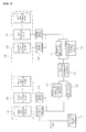
Fig. 1 is a perspective view of an apparatus for recovery of gas according to an embodiment of the present disclosure. -
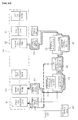
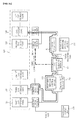
Figs. 2a to 2e are reference views for illustrating a enriching process performed by an apparatus for recovery of gas according to an embodiment of the present disclosure. - The present disclosure is directed to a technique capable of maximizing a concentration rate of a recovery gas when separating an feed gas into a permeation gas and a recovery gas through a gas separation membrane module and recovering the recovery gas.
- Generally, in order to increase a concentration rate of a target gas, it is assumed to use a plurality of gas separation membrane modules. However, the present disclosure proposes to maximize a concentration rate of a target gas by using a single gas separation membrane module.
- The gas separation membrane module employed in the present disclosure allows a highly permeable gas having a relatively small molecular size (hereinafter, referred to as a 'permeation gas') to pass through pores and also allows a less permeable gas having a relatively great molecular size (hereinafter, referred to as a 'recovery gas') to remain in the gas separation membrane module and thus be recovered. If an feed gas is supplied to the gas separation membrane module, the feed gas is separated into a permeation gas and a recovery gas by means of the gas separation membrane module. In addition, a target gas represents a gas to be finally recovered through the gas separation membrane module, for example SF6 contained in a waste gas. The target gas (SF6) is contained in the waste gas with a certain concentration, and if the waste gas is separated into a permeation gas and a recovery gas by means of the gas separation membrane module, most of the target gas is included in the recovery gas and a small amount of target gas is included in the permeation gas.
- In the present disclosure, a plurality of gas storage tanks is applied to increase a concentration rate of the target gas through a single gas separation membrane module, and a plurality of enriching processes using the single gas separation membrane module and the plurality of gas storage tanks are performed in order. By performing the plurality of enriching processes in order, a concentration of the target gas included in the recovery gas may gradually increase.
- Hereinafter, an apparatus and method for recovery of gas according to an embodiment of the present disclosure will be described in detail with reference to the accompanying drawings.
- Referring to
Fig. 1 , an apparatus for recovery of gas according to an embodiment of the present disclosure includes a wastegas supply unit 110, a plurality ofgas storage tanks 120, a first feedpressure control device 131, a second feedpressure control device 132, a gasseparation membrane module 140, afirst SC regulator 151 and asecond SC regulator 152. - The waste
gas supply unit 110 plays a role of supplying a waste gas containing a target gas to a firstgas storage tank 121. The target gas means a gas to be recovered through the gasseparation membrane module 140, and the waste gas containing a target gas may be a waste gas containing SF6 or a fluoride gas such as NF3, CF4 or the like, and the target gas may be SF6, NF3, CF4 or the like. The target gas is mixed in the waste gas with a certain concentration. In the following description, the waste gas is selected as SF6. - The plurality of
gas storage tanks 120 stores a permeation gas and a recovery gas generated in each enriching process and supplies a gas stored in the gasseparation membrane module 140 as an feed gas. - The enriching process means a process for separating a gas into a permeation gas and a recovery gas, which is performed by the gas
separation membrane module 140. In the present disclosure, a plurality of enriching processes are applied. Here, different kinds of feed gases are injected into the gasseparation membrane module 140 when the plurality of enriching processes are performed, and a permeation gas and a recovery gas separated in each enriching process is selectively stored in the plurality of gas storage tanks. - In addition, the plurality of enriching processes are performed, a enriching process in a forward direction and a enriching process in a rearward direction are performed alternately. Generally, if an feed gas is injected into one end of the gas
separation membrane module 140, a recovery gas is recovered through the other end of the gasseparation membrane module 140, which is a one-directional gas recovery manner. However, in the present disclosure, a bi-directional gas recovery manner in which a gas may be recovered in both a forward direction and a rearward direction is applied. In a state where the gasseparation membrane module 140 has both a first end and a second end, the forward direction means a gas flow from the first end of the gasseparation membrane module 140 to the second end, and the rearward direction means a gas flow from the second end of the gasseparation membrane module 140 to the first end, which is opposite to the forward direction. In order to treat a gas flow in the forward direction, a first feedpressure control device 131 and afirst SC regulator 151 are provided, and in order to treat a gas flow in the rearward direction, a second feedpressure control device 132 and asecond SC regulator 152 are provided, as described in detail later. - In the plurality of enriching processes, a (2n-1)th enriching process (n is an integer) is performed in the forward direction, and a 2nth enriching process (n is an integer) is performed in the rearward direction. The plurality of enriching processes will be described in detail below.
- In a first enriching process (see
Fig. 2a ), a gas stored in the firstgas storage tank 121 is supplied to the gasseparation membrane module 140 in the forward direction. In addition, a first permeation gas separated by the gasseparation membrane module 140 is emitted, and a first recovery gas separated by the gasseparation membrane module 140 is stored in the secondgas storage tank 122. The firstgas storage tank 121 stores the waste gas supplied from the wastegas supply unit 110 and a second permeation gas separated by a second enriching process, described later. - In a second enriching process (see
Fig. 2b ), a gas stored in the secondgas storage tank 122 is supplied to the gasseparation membrane module 140 in the rearward direction and separated into a second permeation gas and a second recovery gas. Here, the second permeation gas is stored in the firstgas storage tank 121, and the second recovery gas is stored in a thirdgas storage tank 123. In addition, in a third enriching process (seeFig. 2c ), a gas stored in the thirdgas storage tank 123 is supplied to the gasseparation membrane module 140 in the forward direction and separated into a third permeation gas and a third recovery gas. Here, the third permeation gas is stored in the secondgas storage tank 122, and the third recovery gas is stored in a fourthgas storage tank 124. - When each enriching process is performed, a relation between a gas storage tank for supplying an feed gas to the gas
separation membrane module 140 and a gas storage tank for storing a permeation gas and a recovery gas separated by the gasseparation membrane module 140 may be arranged as follows. - In an nth enriching process (n is an integer), a gas stored in an nth gas storage tank is supplied to the gas
separation membrane module 140 and separated into an nth permeation gas and an nth recovery gas, wherein the nth permeation gas is stored in a (n-1)th gas storage tank and the nth recovery gas is stored in a (n+1)th gas storage tank. However, the first permeation gas of the first enriching process is not stored in a gas storage tank but emitted. - Meanwhile, in view of the kind of gas stored in the gas storage tank, the second
gas storage tank 122 stores a first recovery gas and a third permeation gas, the thirdgas storage tank 123 stores a second recovery gas and a fourth permeation gas, and the fourthgas storage tank 124 stores a third recovery gas and a fifth permeation gas. If this is arranged, a (n+1)th gas storage tank (n is an integer) stores an nth recovery gas and a (n+2)th permeation gas. However, the firstgas storage tank 121 stores a waste gas supplied from the wastegas supply unit 110 and a second permeation gas. - When the plurality of enriching processes are performed in order, since the first permeation gas of the first enriching process is emitted, gases stored in the second
gas storage tank 122 to the nth gas storage tank through the plurality of enriching processes may be regarded as gases separated from the first recovery gas. In addition, since a recovery gas separated from a gas stored in a gas storage tank of a former stage is stored in a gas storage tank of a later stage, as the enriching process progresses, a target gas concentration in the recovery gas gradually increases. - The plurality of enriching processes, namely the first enriching process to the nth enriching process, may be performed in order, and the order may also be changed according to an operation condition. For example, the method for recovery of gas may be performed in the order of the first enriching process, the second enriching process, ··, the nth enriching process, or in the order of the first enriching process, the second enriching process, the third enriching process, the first enriching process, and the fourth enriching process.
- Meanwhile, a
compression device 160 having a compressor shape may be further provided at a front end of each gas storage tank. Thecompression device 160 plays a role of compressing a gas supplied to and stored in the gas storage tank, and the gas emitted from the gas storage tank and supplied to the gasseparation membrane module 140 does not pass through thecompression device 160. - Next, the first feed
pressure control device 131 and the second feedpressure control device 132 play a role of controlling a gas pressure constantly so that the corresponding gas is supplied to the gasseparation membrane module 140 at a constant pressure, when a gas stored in each gas storage tank is supplied to the gasseparation membrane module 140. The first feedpressure control device 131 controls a gas pressure when a enriching process in the forward direction (or, the (2n-1)th enriching process) is performed, and the second feedpressure control device 132 controls a gas pressure when a enriching process in the rearward direction (or, the 2nth enriching process) is performed. The gas pressures controlled by the first feedpressure control device 131 and the second feedpressure control device 132 may be controlled to the same pressure P0. - The gas
separation membrane module 140 plays a role of separating a gas supplied from each gas storage tank into a permeation gas and a recovery gas, and the first enriching process and the second enriching process to the nth enriching process are performed in order by the gasseparation membrane module 140 as described above. - The gas
separation membrane module 140 is a separation membrane assembly in a hollow fiber shape having pores on its surface. Here, a gas having a relatively small molecular size such as O2, N2, CO2 or the like, other than SF6, rapidly passes through the pores of the separation membrane and is emitted, and SF6 having a relatively great molecular size does not pass through the pores but is first recovered at one end of the separation membrane. The gas emitted through the pores of the separation membrane is a permeation gas, and the gas recovered at one end of the separation membrane is a recovery gas. At this time, not only a gas having a relatively small molecular size (O2, N2, CO2 or the like) but also a SF6 gas having a relatively great molecular size is emitted through the pores of the separation membrane. However, since the SF6 gas has permeability lower than the permeability of O2, N2, CO2 or the like, the SF6 gas may be recovered as a recovery gas. Therefore, gases such as O2, N2, CO2 or the like may be substantially regarded as highly permeable gases, and the SF6 gas may be regarded as a less permeable gas. - The
first SC regulator 151 and thesecond SC regulator 152 play a role of controlling a stage-cut (SC) value of the gasseparation membrane module 140 in each enriching process. In detail, thefirst SC regulator 151 controls a SC value of the gasseparation membrane module 140 when a enriching process in the forward direction, namely a (2n-1)th enriching process, is performed, and thesecond SC regulator 152 controls a SC value of the gasseparation membrane module 140 when a enriching process in the rearward direction, namely a 2nth enriching process, is performed. - The SC value controlled by the
first SC regulator 151 and thesecond SC regulator 152 means a ratio of a permeation gas flow rate in comparison to an feed gas flow rate, as shown in Equation 2 below. For example, if the SC value is 0.95, a permeation gas flow rate in comparison to the feed gas flow rate is 95%, and a recovery gas flow rate is 5%, which means 5% of the entire feed gas is recovered (seeEquations 1 and 2).

- Meanwhile, the SC value applied to each enriching process is set so that the SC value decreases as the enriching process progresses. As described above, in a state where the first permeation gas separated in the first enriching process is emitted, a following enriching process is performed based on the first recovery gas, and a recovery gas separated from a gas stored in a gas storage tank of a former stage is stored in a gas storage tank of a later stage. Therefore, as the enriching process progresses, a flow rate of the recovery gas becomes relatively greater, and a flow rate of the permeation gas becomes relatively smaller.
- The SC value applied to each enriching process is determined by a target enrichment ratio (e), selectivity (α) of the gas
separation membrane module 140, and a target gas concentration (xf) of the feed gas. The target enrichment ratio (e) means a ratio of a target gas concentration (xr) in the recovery gas in comparison to a target gas concentration (xf) in the feed gas (see Equation 3). If the target gas concentration (xr) in the recovery gas is set in a state where the target gas concentration (xf) in the feed gas is given, the target enrichment ratio (e) may be calculated. The selectivity (α) of the gasseparation membrane module 140 means a ratio of permeability (PA) of the permeation gas in comparison to permeability (PB) of the target gas (see Equation 4). - An nth SC value (θn) applied to the nth enriching process is defined according to Equation 5 below, and the SC value applied to each enriching process decreases as the enriching process progresses.

where e represents a target enrichment ratio, xf represents a target gas concentration in an feed gas, and xr represents a target gas concentration in a recovery gas.
where α represents selectivity of the gasseparation membrane module 140, PB represents permeability of the target gas, and PA represents permeability of the permeation gas.
where θn represents a SC value in the nth enriching process, en represents a target enrichment ratio of the nth enriching process, xn represents a target gas concentration of the feed gas injected into the gasseparation membrane module 140 in the nth enriching process, and α represents selectivity of the gasseparation membrane module 140. - Meanwhile, even though it has been explained that the first permeation gas is not stored in the gas storage tank but emitted, this is on the premise that the target gas concentration in the first permeation gas, namely a SF6 concentration in the first permeation gas, is sufficiently low to meet the emission standard. If the target gas concentration in the first permeation gas does not conform to the emission standard, the first permeation gas may be stored in the first
gas storage tank 121 to pass through the first enriching process again. In addition, the second permeation gas, the third permeation gas or the like are stored in the gas storage tank and pass through a enriching process. Here, the second permeation gas, the third permeation gas or the like may also not be stored in a gas storage tank but emitted if a target gas concentration contained in the corresponding permeation gas conforms to the emission standard. - In order to determine whether the target gas concentration in the permeation gas conforms to the emission standard, a target gas concentration in the corresponding permeation gas should be accurately calculated. Here, the target gas concentration of a permeation gas generated in each enriching process may be calculated through Equation 6 below.

where yn represents a target gas concentration included in the nth permeation gas of the nth enriching process, xn represents a target gas concentration in the feed gas injected into the gasseparation membrane module 140 in the nth enriching process, and α represents selectivity of the gasseparation membrane module 140. - In addition, an optimal membrane area of a gas separation membrane for performing a plurality of enriching processes according to the present disclosure may be designed. Here, the optimal membrane area of a gas separation membrane is designed according to
Equation 7.
- where A represents a membrane area of the gas
separation membrane module 140, f1 represents an feed gas flow rate of a first enriching process, θ1 represents a first SC value of the first enriching process, P0 represents a feed pressure of the feed gas injected into the gasseparation membrane module 140, PA represents permeability of the permeation gas, PB represents permeability of the target gas, and x0 represents a target gas concentration in a waste gas. - Meanwhile, when the plurality of enriching processes are performed, an optimal operation time of each enriching process may be set.
- First, an optimal operation time of the first enriching process may be arranged as follows.
- During an operation time (T1) of the first enriching process, a volume (Vin) of a waste gas flowing into the first gas storage tank and a volume (Vout) of an feed gas supplied from the first gas storage tank to the gas separation membrane module are arranged as in Equations 8 and 9 below. Based on Equations 8 and 9, a volume decrement (Vout-Vin) in the first gas storage tank at the completion point of the first enriching process is arranged as in Equation 10.
- Meanwhile, when the first enriching process is performed, the pressure in the first gas storage tank is highest at a start point of the first enriching process (Pi,max), and at this time, the volume in the first gas storage tank is arranged as C1·P1,max (C1 represents capacity of the first gas storage tank). When the first enriching process is performed, the gas volume in the first gas storage tank slowly decreases, and accordingly the gas pressure in the first gas storage tank also slowly decreases. At this time, if the gas pressure in the first gas storage tank is smaller than a feed pressure (P0) to the gas separation membrane module, gas may not be supplied to the gas separation membrane module. Therefore, in the first enriching process, the minimum volume in the first gas storage tank should be greater than C1·P0. For this reason, in the first enriching process, the maximum decrement (Vo-i,max) in the first gas storage tank may be arranged as in Equation 11.
- In this arrangement, a volume decrement (Vout-Vin) in the first gas storage tank at a completion point of the first enriching process should be equal to or smaller than a maximum decrement (Vo-i,max) of the gas in the first gas storage tank in the first enriching process (see Equation 12), and an optimal operation time of the first enriching process satisfying this condition may be set as in Equation 13.

where Vin represents a volume of a waste gas flowing into the first gas storage tank during an operation time of the first enriching process, T1 represents an operation time of the first enriching process, and f0 represents a flow rate of the waste gas in the first enriching process.
where Vout represents a volume of a waste gas supplied from the first gas storage tank to the gas separation membrane module during an operation time of the first enriching process, T1 represents an operation time of the first enriching process, and fF,1 represents a flow rate of the feed gas in the first enriching process.

where Vo-i,max represents a maximum decrement of gas in the first gas storage tank in the first enriching process, C1 represents capacity of the first gas storage tank, P1,max represents a maximum gas pressure in the first gas storage tank, and P0 represents a feed pressure of the feed gas supplied to the gas separation membrane module.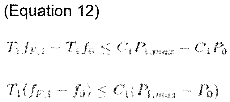

where T1 represents an operation time of the first enriching process, C1 represents capacity of the first gas storage tank, P1,max represents a maximum gas pressure in the first gas storage tank, P0 represents a feed pressure of the feed gas supplied to the gas separation membrane module, fF,1 represents a flow rate of the feed gas in the first enriching process, and f0 represents a flow rate of a waste gas in the first enriching process. - Heretofore, the optimal operation time of the first enriching process has been described. However, the optimal operation time may also be set with respect to the nth enriching process, without being limited to the first enriching process. An optimal operation time of the nth enriching process (n is a natural number equal to or greater than 2) is set as in Equation 14 below. In the nth enriching process (n is a natural number equal to or greater than 2), the waste gas is not supplied to the nth gas storage tank (n is a natural number equal to or greater than 2), and thus the flow rate (f0) of the waste gas is excluded from the variables.

where Tn (n is a natural number equal to or greater than 2) represents an operation time of the nth enriching process, Cn represents capacity of the first gas storage tank, Pn,max represents a maximum gas pressure of the first gas storage tank, P0 represents a feed pressure of the feed gas supplied to the gas separation membrane module, and fF,n represents a flow rate of the feed gas in the nth enriching process. - The flow rate (fF,1) of the feed gas in the first enriching process and the flow rate (fF,n) of the feed gas in the nth enriching process, applied to Equations 13 and 14, may be arranged as in Equations 15 and 16, respectively.

where fF,1 represents a flow rate of the feed gas in the first enriching process, θ1 represents a first SC value of the first enriching process, A represents a membrane area of the gas separation membrane module, P0 represents a feed pressure of the feed gas injected into the gas separation membrane module, PA represents permeability of the permeation gas, PB represents permeability of the target gas, and x0 represents a target gas concentration in the waste gas.
where fF,n (n is an integer) represents a flow rate of the feed gas in the nth enriching process, θn represents a first SC value of the nth enriching process, A represents a membrane area of the gas separation membrane module, P0 represents a feed pressure of the feed gas injected into the gas separation membrane module, PA represents permeability of the permeation gas, PB represents permeability of the target gas, and xn represents a target gas concentration in the feed gas injected into the gas separation membrane module in the nth enriching process. - In addition, the flow rate (fF,1) of the feed gas in the first enriching process may be arranged as in Equation 17 below in view of the waste gas flow rate (f0) and the operation time (Ti) of the enriching process. Equation 17 below is derived on the assumption that an entire volume (f0·ΣTi) of gas treated through the plurality of enriching processes of the gas recovery apparatus according to the present disclosure corresponds to a volume (fF,1·T1) of the feed gas injected into the gas separation membrane module during an operation time of the first enriching process.
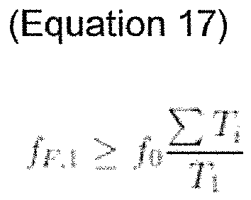
where fF,1 represents a flow rate of the feed gas in the first enriching process, f0 represents a waste gas flow rate, ΣTi represents a sum of operation times of the plurality of enriching processes, and T1 represents an operation time of the first enriching process.[Detailed Description of Main Elements] 110: waste gas supply unit 120: plurality of gas storage tanks 121: first gas storage tank 122: second gas storage tank 123: third gas storage tank 124: fourth gas storage tank 131: first feed pressure control device 132: second feed pressure control device 140: gas separation membrane module 151: first SC regulator 152: second SC regulator 160: compression device
Claims (16)
- An apparatus for recovery of gas, comprising:a gas separation membrane module (140) for performing an n number of enriching processes (n is an integer) and separating an feed gas into a permeation gas and a recovery gas through each enriching process; anda (n+1) number of gas storage tanks,wherein in an nth enriching process, a gas stored in an nth gas storage tank is supplied to the gas separation membrane module (140) and separated into an nth permeation gas and an nth recovery gas, and the nth permeation gas is stored in a (n-1)th gas storage tank and the nth recovery gas is stored in a (n+1)th gas storage tank,wherein a (2n-1)th enriching process (n is an integer) is performed in a forward direction, and a 2nth enriching process (n is an integer) is performed in a rearward direction, andwherein the forward direction represents a gas flow from a first end of the gas separation membrane module (140) to a second end thereof, and the rearward direction represents a direction opposite to the forward direction.
- The apparatus for recovery of gas according to claim 1,
wherein the nth recovery gas and a (n+2)th permeation gas are stored in the (n+1)th gas storage tank. - The apparatus for recovery of gas according to claim 1 or 2, further comprising:a first stage-cut (SC) regulator (151) for controlling a SC value of the gas separation membrane module (140) when the (2n-1)th enriching process is performed; anda second SC regulator (152) for controlling a SC value of the gas separation membrane module (140) when the 2nth enriching process is performed.
- The apparatus for recovery of gas according to one of claims 1 to 3, wherein a SC value (θn) of the nth enriching process is set according to the following equation:

where θn represents a SC value in the nth enriching process, en represents a target enrichment ratio in the nth enriching process, xn represents a target gas concentration of the feed gas injected into the gas separation membrane module (140) in the nth enriching process, and α represents selectivity of the gas separation membrane module (140). - The apparatus for recovery of gas according to one of claims 1 to 4, further comprising a first feed pressure control device (131) and a second feed pressure control device (132),
wherein the first feed pressure control device (131) controls a gas pressure supplied to the gas separation membrane module (140) to a constant pressure when the (2n-1)th enriching process is performed,
wherein the second feed pressure control device (132) controls a gas pressure supplied to the gas separation membrane module (140) to a constant pressure when the 2nth enriching process is performed, and
wherein gas pressures controlled by the first feed pressure control device (131) and the second feed pressure control device (132) are controlled to the same pressure (P0). - The apparatus for recovery of gas according to one of claims 1 to 5, further comprising a waste gas supply unit (110) for supplying a waste gas containing a target gas to a first gas storage tank (121),
wherein the first gas storage tank (121) stores the waste gas supplied from the waste gas supply unit (110) and a second permeation gas, and a first permeation gas of the first enriching process is emitted. - The apparatus for recovery of gas according to one of claims 1 to 6, wherein a target gas concentration (yn) of the nth permeation gas separated in the nth enriching process is calculated through the following equation:

where yn represents a target gas concentration included in the nth permeation gas of the nth enriching process, xn represents a target gas concentration in the feed gas injected into the gas separation membrane module (140) in the nth enriching process, and α represents selectivity of the gas separation membrane module (140). - The apparatus for recovery of gas according to one of claims 1 to 7, wherein a membrane area of the gas separation membrane module (140) is set according to the following equation:

where A represents a membrane area of the gas separation membrane module (140), f1 represents an feed gas flow rate of a first enriching process, θ1 represents a first SC value of the first enriching process, P0 represents a feed pressure of the feed gas injected into the gas separation membrane module (140), PA represents permeability of the permeation gas, PB represents permeability of the target gas, and x0 represents a target gas concentration in a waste gas. - The apparatus for recovery of gas according to one of claims 1 to 8, wherein an operation time (T1) of a first enriching process meets Equation 1 below, and an operation time (Tn) of the nth enriching process (n is a natural number equal to or greater than 2) meets Equation 2 below:

where T1 represents an operation time of the first enriching process, C1 represents capacity of the first gas storage tank (121), P1,max represents a maximum gas pressure in the first gas storage tank (121), P0 represents a feed pressure of the feed gas supplied to the gas separation membrane module (140), fF,1 represents a flow rate of the feed gas in the first enriching process, and f0 represents a flow rate of a waste gas in the first enriching process.
where Tn (n is a natural number equal to or greater than 2) represents an operation time of the nth enriching process, Cn represents capacity of the first gas storage tank (121), Pn,max represents a maximum gas pressure of the first gas storage tank (121), P0 represents a feed pressure of the feed gas supplied to the gas separation membrane module (140), and fF,n represents a flow rate of the feed gas in the nth enriching process. - A method for recovery of gas,
wherein the method for recovery of gas uses a single gas separation membrane module (140) and a (n+1) number of gas storage tanks (n is an integer),
wherein the gas separation membrane module (140) performs an n number of enriching processes (n is an integer), and an feed gas is separated into a permeation gas and a recovery gas through each enriching process,
wherein in an nth enriching process, a gas stored in an nth gas storage tank is supplied to the gas separation membrane module (140) and separated into an nth permeation gas and an nth recovery gas, and the nth permeation gas is stored in a (n-1)th gas storage tank and the nth recovery gas is stored in a (n+1)th gas storage tank,
wherein a (2n-1)th enriching process (n is an integer) is performed in a forward direction, and a 2nth enriching process (n is an integer) is performed in a rearward direction, and
wherein the forward direction represents a gas flow from a first end of the gas separation membrane module (140) to a second end thereof, and the rearward direction represents a direction opposite to the forward direction. - The method for recovery of gas according to claim 10,
wherein a first permeation gas of a first enriching process is emitted, and
wherein a waste gas supplied from a waste gas supply unit (110) and a second permeation gas are stored in a first gas storage tank. - The method for recovery of gas according to claim 10 or 11,
wherein a SC regulator for controlling a SC value of the gas separation membrane module (140) when the nth enriching process is performed is provided, and SC value (θn) of the nth enriching process is set according to the following equation:
where θn represents a SC value in the nth enriching process, en represents a target enrichment ratio in the nth enriching process, xn represents a target gas concentration of the feed gas injected into the gas separation membrane module (140) in the nth enriching process, and α represents selectivity of the gas separation membrane module (140). - The method for recovery of gas according to one of claims 10 to 12, wherein a pressure of a gas supplied to the gas separation membrane module (140) is controlled constantly through each enriching process.
- The method for recovery of gas according to one of claims 10 to 13, wherein a target gas concentration (yn) of the nth permeation gas separated in the nth enriching process is calculated through the following equation:

where yn represents a target gas concentration included in the nth permeation gas of the nth enriching process, xn represents a target gas concentration in the feed gas injected into the gas separation membrane module (140) in the nth enriching process, and α represents selectivity of the gas separation membrane module (140). - The method for recovery of gas according to one of claims 10 to 14, wherein a membrane area of the gas separation membrane module (140) is set according to the following equation:

where A represents a membrane area of the gas separation membrane module (140), f1 represents an feed gas flow rate of a first enriching process, θ1 represents a first SC value of the first enriching process, P0 represents a feed pressure of the feed gas injected into the gas separation membrane module (140), PA represents permeability of the permeation gas, PB represents permeability of the target gas, and x0 represents a target gas concentration in a waste gas. - The method for recovery of gas according to one of claims 10 to 15, wherein an operation time (T1) of a first enriching process meets Equation 1 below, and an operation time (Tn) of the nth enriching process (n is a natural number equal to or greater than 2) meets Equation 2 below:

where T1 represents an operation time of the first enriching process, C1 represents capacity of the first gas storage tank, P1,max represents a maximum gas pressure in the first gas storage tank, P0 represents a feed pressure of the feed gas supplied to the gas separation membrane module (140), fF,1 represents a flow rate of the feed gas in the first enriching process, and f0 represents a flow rate of a waste gas in the first enriching process.
where Tn (n is a natural number equal to or greater than 2) represents an operation time of the nth enriching process, Cn represents capacity of the first gas storage tank, Pn,max represents a maximum gas pressure of the first gas storage tank, P0 represents a feed pressure of the feed gas supplied to the gas separation membrane module (140), and fF,n represents a flow rate of the feed gas in the nth enriching process.
Applications Claiming Priority (1)
| Application Number | Priority Date | Filing Date | Title |
|---|---|---|---|
| KR1020140075910A KR101526879B1 (en) | 2014-06-20 | 2014-06-20 | Apparatus and method for recovery of retentate |
Publications (2)
| Publication Number | Publication Date |
|---|---|
| EP2957333A1 true EP2957333A1 (en) | 2015-12-23 |
| EP2957333B1 EP2957333B1 (en) | 2020-07-15 |
Family
ID=51421813
Family Applications (1)
| Application Number | Title | Priority Date | Filing Date |
|---|---|---|---|
| EP14180713.1A Active EP2957333B1 (en) | 2014-06-20 | 2014-08-12 | Apparatus and method for recovery of gas |
Country Status (2)
| Country | Link |
|---|---|
| EP (1) | EP2957333B1 (en) |
| KR (1) | KR101526879B1 (en) |
Families Citing this family (2)
| Publication number | Priority date | Publication date | Assignee | Title |
|---|---|---|---|---|
| KR101783429B1 (en) * | 2016-01-06 | 2017-09-29 | 한국과학기술연구원 | Apparatus and method for recovery of high permeable gas |
| KR101840732B1 (en) * | 2016-01-06 | 2018-05-04 | 한국과학기술연구원 | Apparatus and method for bidirectional high permeable gas separation |
Citations (5)
| Publication number | Priority date | Publication date | Assignee | Title |
|---|---|---|---|---|
| DE19837845A1 (en) * | 1998-08-20 | 2000-02-24 | Solvay Fluor & Derivate | Separation of sulfur trifluoride/nitrogen or air mixtures used as filling gas for underground cables comprises contacting the mixtures with hydrophobic zeolite |
| US6389845B1 (en) * | 1999-10-05 | 2002-05-21 | American Air Liquide, Inc. | Method and apparatus for separation of SF6 from CF4 /air-containing gas stream |
| US6454837B1 (en) * | 1998-08-20 | 2002-09-24 | Solvay Fluor Und Derivate Gmbh | Separation of gases containing SF6 |
| US20120260799A1 (en) * | 2011-04-15 | 2012-10-18 | Korea Institute Of Science And Technology | Apparatus and method for recovery of sulfur hexafluoride |
| KR20130118138A (en) | 2012-04-19 | 2013-10-29 | 주식회사 바인트리 | Terminal and server having function for providing advertisement contents using qr code |
Family Cites Families (4)
| Publication number | Priority date | Publication date | Assignee | Title |
|---|---|---|---|---|
| US5858065A (en) * | 1995-07-17 | 1999-01-12 | American Air Liquide | Process and system for separation and recovery of perfluorocompound gases |
| JP4089230B2 (en) * | 2001-01-25 | 2008-05-28 | 宇部興産株式会社 | Halogen compound gas separation and recovery apparatus and separation and recovery method |
| KR20120077322A (en) * | 2010-12-30 | 2012-07-10 | 한국과학기술연구원 | Apparatus and method for recovery of sulfur hexafluoride |
| KR101482612B1 (en) * | 2013-10-02 | 2015-01-14 | 한국과학기술연구원 | Apparatus and method for recovery of sulfur hexafluoride |
-
2014
- 2014-06-20 KR KR1020140075910A patent/KR101526879B1/en not_active Expired - Fee Related
- 2014-08-12 EP EP14180713.1A patent/EP2957333B1/en active Active
Patent Citations (6)
| Publication number | Priority date | Publication date | Assignee | Title |
|---|---|---|---|---|
| DE19837845A1 (en) * | 1998-08-20 | 2000-02-24 | Solvay Fluor & Derivate | Separation of sulfur trifluoride/nitrogen or air mixtures used as filling gas for underground cables comprises contacting the mixtures with hydrophobic zeolite |
| US6454837B1 (en) * | 1998-08-20 | 2002-09-24 | Solvay Fluor Und Derivate Gmbh | Separation of gases containing SF6 |
| US6389845B1 (en) * | 1999-10-05 | 2002-05-21 | American Air Liquide, Inc. | Method and apparatus for separation of SF6 from CF4 /air-containing gas stream |
| US20120260799A1 (en) * | 2011-04-15 | 2012-10-18 | Korea Institute Of Science And Technology | Apparatus and method for recovery of sulfur hexafluoride |
| KR101249261B1 (en) | 2011-04-15 | 2013-04-01 | 한국과학기술연구원 | Apparatus and method for recovery of sulfur hexafluoride |
| KR20130118138A (en) | 2012-04-19 | 2013-10-29 | 주식회사 바인트리 | Terminal and server having function for providing advertisement contents using qr code |
Also Published As
| Publication number | Publication date |
|---|---|
| EP2957333B1 (en) | 2020-07-15 |
| KR101526879B1 (en) | 2015-06-09 |
Similar Documents
| Publication | Publication Date | Title |
|---|---|---|
| US20250050273A1 (en) | System and method for production of synthetic fuel through co2 capture and water splitting | |
| US8623120B2 (en) | Apparatus and method for recovery of sulfur hexafluoride | |
| EP2163294B1 (en) | System and method for recovery of co2 by aqueous carbonate flue gas capture and high efficiency bipolar membrane electrodialysis | |
| KR101505920B1 (en) | Apparatus and method for recovery of sulfur hexafluoride | |
| EP3441505A1 (en) | Ammonia production method | |
| EP2070582B1 (en) | Method and equipment for the enrichment of heavy oxygen isotopes | |
| RU2598094C1 (en) | Oxygen isotope enrichment method | |
| KR20120077322A (en) | Apparatus and method for recovery of sulfur hexafluoride | |
| EP2957333B1 (en) | Apparatus and method for recovery of gas | |
| KR20140049702A (en) | Biogas upgrading process and plants using microporous hollow fiber membranes | |
| US9687776B2 (en) | Apparatus and method for recovery of target gas | |
| US20120240764A1 (en) | Carbon dioxide isolating device and method | |
| KR101275772B1 (en) | Membrane module and a fluorinated gas concentrator comprising the same | |
| KR101482612B1 (en) | Apparatus and method for recovery of sulfur hexafluoride | |
| KR101420082B1 (en) | Appratus for separating and enriching fluorinated gas, and the method for separating and enriching of fluorinated gas thereby | |
| JP6136074B2 (en) | Nitrogen separation apparatus and method | |
| KR101420767B1 (en) | Appratus for enriching and recovering fluorinated gas using membrane, and the method for enriching and recoverying of fluorinated gas thereby | |
| KR101275774B1 (en) | Appratus for enriching fluorinated gas, and the method for enrichment of fluorinated gas thereby | |
| US20120180656A1 (en) | Apparatus and method for power-free filtration using osmotic pressure | |
| KR101576803B1 (en) | Apparatus and method for recovery of retentate using gas separation membrane | |
| KR101395092B1 (en) | Appratus for separating and recovering fluorinated gas, and the method for separating and recovering of fluorinated gas thereby | |
| KR101840732B1 (en) | Apparatus and method for bidirectional high permeable gas separation | |
| KR101636767B1 (en) | Apparatus and method for recovery of retentate | |
| KR101636770B1 (en) | Apparatus and method for recovery of retentate | |
| KR101833882B1 (en) | Method for separation of fluorinated gas using multi-stage gas separation process comprising high-selectivity hollow fiber membrane modules |
Legal Events
| Date | Code | Title | Description |
|---|---|---|---|
| PUAI | Public reference made under article 153(3) epc to a published international application that has entered the european phase |
Free format text: ORIGINAL CODE: 0009012 |
|
| 17P | Request for examination filed |
Effective date: 20140902 |
|
| AK | Designated contracting states |
Kind code of ref document: A1 Designated state(s): AL AT BE BG CH CY CZ DE DK EE ES FI FR GB GR HR HU IE IS IT LI LT LU LV MC MK MT NL NO PL PT RO RS SE SI SK SM TR |
|
| AX | Request for extension of the european patent |
Extension state: BA ME |
|
| STAA | Information on the status of an ep patent application or granted ep patent |
Free format text: STATUS: EXAMINATION IS IN PROGRESS |
|
| 17Q | First examination report despatched |
Effective date: 20190801 |
|
| GRAP | Despatch of communication of intention to grant a patent |
Free format text: ORIGINAL CODE: EPIDOSNIGR1 |
|
| STAA | Information on the status of an ep patent application or granted ep patent |
Free format text: STATUS: GRANT OF PATENT IS INTENDED |
|
| INTG | Intention to grant announced |
Effective date: 20200131 |
|
| RAP1 | Party data changed (applicant data changed or rights of an application transferred) |
Owner name: KOREA INSTITUTE OF SCIENCE AND TECHNOLOGY |
|
| GRAS | Grant fee paid |
Free format text: ORIGINAL CODE: EPIDOSNIGR3 |
|
| GRAA | (expected) grant |
Free format text: ORIGINAL CODE: 0009210 |
|
| STAA | Information on the status of an ep patent application or granted ep patent |
Free format text: STATUS: THE PATENT HAS BEEN GRANTED |
|
| AK | Designated contracting states |
Kind code of ref document: B1 Designated state(s): AL AT BE BG CH CY CZ DE DK EE ES FI FR GB GR HR HU IE IS IT LI LT LU LV MC MK MT NL NO PL PT RO RS SE SI SK SM TR |
|
| REG | Reference to a national code |
Ref country code: GB Ref legal event code: FG4D Ref country code: CH Ref legal event code: EP |
|
| REG | Reference to a national code |
Ref country code: DE Ref legal event code: R096 Ref document number: 602014067669 Country of ref document: DE |
|
| REG | Reference to a national code |
Ref country code: IE Ref legal event code: FG4D |
|
| REG | Reference to a national code |
Ref country code: AT Ref legal event code: REF Ref document number: 1290352 Country of ref document: AT Kind code of ref document: T Effective date: 20200815 |
|
| REG | Reference to a national code |
Ref country code: LT Ref legal event code: MG4D |
|
| REG | Reference to a national code |
Ref country code: AT Ref legal event code: MK05 Ref document number: 1290352 Country of ref document: AT Kind code of ref document: T Effective date: 20200715 |
|
| REG | Reference to a national code |
Ref country code: NL Ref legal event code: MP Effective date: 20200715 |
|
| PG25 | Lapsed in a contracting state [announced via postgrant information from national office to epo] |
Ref country code: FI Free format text: LAPSE BECAUSE OF FAILURE TO SUBMIT A TRANSLATION OF THE DESCRIPTION OR TO PAY THE FEE WITHIN THE PRESCRIBED TIME-LIMIT Effective date: 20200715 Ref country code: NO Free format text: LAPSE BECAUSE OF FAILURE TO SUBMIT A TRANSLATION OF THE DESCRIPTION OR TO PAY THE FEE WITHIN THE PRESCRIBED TIME-LIMIT Effective date: 20201015 Ref country code: GR Free format text: LAPSE BECAUSE OF FAILURE TO SUBMIT A TRANSLATION OF THE DESCRIPTION OR TO PAY THE FEE WITHIN THE PRESCRIBED TIME-LIMIT Effective date: 20201016 Ref country code: SE Free format text: LAPSE BECAUSE OF FAILURE TO SUBMIT A TRANSLATION OF THE DESCRIPTION OR TO PAY THE FEE WITHIN THE PRESCRIBED TIME-LIMIT Effective date: 20200715 Ref country code: AT Free format text: LAPSE BECAUSE OF FAILURE TO SUBMIT A TRANSLATION OF THE DESCRIPTION OR TO PAY THE FEE WITHIN THE PRESCRIBED TIME-LIMIT Effective date: 20200715 Ref country code: ES Free format text: LAPSE BECAUSE OF FAILURE TO SUBMIT A TRANSLATION OF THE DESCRIPTION OR TO PAY THE FEE WITHIN THE PRESCRIBED TIME-LIMIT Effective date: 20200715 Ref country code: LT Free format text: LAPSE BECAUSE OF FAILURE TO SUBMIT A TRANSLATION OF THE DESCRIPTION OR TO PAY THE FEE WITHIN THE PRESCRIBED TIME-LIMIT Effective date: 20200715 Ref country code: PT Free format text: LAPSE BECAUSE OF FAILURE TO SUBMIT A TRANSLATION OF THE DESCRIPTION OR TO PAY THE FEE WITHIN THE PRESCRIBED TIME-LIMIT Effective date: 20201116 Ref country code: BG Free format text: LAPSE BECAUSE OF FAILURE TO SUBMIT A TRANSLATION OF THE DESCRIPTION OR TO PAY THE FEE WITHIN THE PRESCRIBED TIME-LIMIT Effective date: 20201015 Ref country code: HR Free format text: LAPSE BECAUSE OF FAILURE TO SUBMIT A TRANSLATION OF THE DESCRIPTION OR TO PAY THE FEE WITHIN THE PRESCRIBED TIME-LIMIT Effective date: 20200715 |
|
| PG25 | Lapsed in a contracting state [announced via postgrant information from national office to epo] |
Ref country code: IS Free format text: LAPSE BECAUSE OF FAILURE TO SUBMIT A TRANSLATION OF THE DESCRIPTION OR TO PAY THE FEE WITHIN THE PRESCRIBED TIME-LIMIT Effective date: 20201115 Ref country code: PL Free format text: LAPSE BECAUSE OF FAILURE TO SUBMIT A TRANSLATION OF THE DESCRIPTION OR TO PAY THE FEE WITHIN THE PRESCRIBED TIME-LIMIT Effective date: 20200715 Ref country code: LV Free format text: LAPSE BECAUSE OF FAILURE TO SUBMIT A TRANSLATION OF THE DESCRIPTION OR TO PAY THE FEE WITHIN THE PRESCRIBED TIME-LIMIT Effective date: 20200715 Ref country code: RS Free format text: LAPSE BECAUSE OF FAILURE TO SUBMIT A TRANSLATION OF THE DESCRIPTION OR TO PAY THE FEE WITHIN THE PRESCRIBED TIME-LIMIT Effective date: 20200715 |
|
| PG25 | Lapsed in a contracting state [announced via postgrant information from national office to epo] |
Ref country code: NL Free format text: LAPSE BECAUSE OF FAILURE TO SUBMIT A TRANSLATION OF THE DESCRIPTION OR TO PAY THE FEE WITHIN THE PRESCRIBED TIME-LIMIT Effective date: 20200715 |
|
| REG | Reference to a national code |
Ref country code: CH Ref legal event code: PL |
|
| REG | Reference to a national code |
Ref country code: DE Ref legal event code: R097 Ref document number: 602014067669 Country of ref document: DE |
|
| PG25 | Lapsed in a contracting state [announced via postgrant information from national office to epo] |
Ref country code: CZ Free format text: LAPSE BECAUSE OF FAILURE TO SUBMIT A TRANSLATION OF THE DESCRIPTION OR TO PAY THE FEE WITHIN THE PRESCRIBED TIME-LIMIT Effective date: 20200715 Ref country code: CH Free format text: LAPSE BECAUSE OF NON-PAYMENT OF DUE FEES Effective date: 20200831 Ref country code: EE Free format text: LAPSE BECAUSE OF FAILURE TO SUBMIT A TRANSLATION OF THE DESCRIPTION OR TO PAY THE FEE WITHIN THE PRESCRIBED TIME-LIMIT Effective date: 20200715 Ref country code: DK Free format text: LAPSE BECAUSE OF FAILURE TO SUBMIT A TRANSLATION OF THE DESCRIPTION OR TO PAY THE FEE WITHIN THE PRESCRIBED TIME-LIMIT Effective date: 20200715 Ref country code: IT Free format text: LAPSE BECAUSE OF FAILURE TO SUBMIT A TRANSLATION OF THE DESCRIPTION OR TO PAY THE FEE WITHIN THE PRESCRIBED TIME-LIMIT Effective date: 20200715 Ref country code: LI Free format text: LAPSE BECAUSE OF NON-PAYMENT OF DUE FEES Effective date: 20200831 Ref country code: SM Free format text: LAPSE BECAUSE OF FAILURE TO SUBMIT A TRANSLATION OF THE DESCRIPTION OR TO PAY THE FEE WITHIN THE PRESCRIBED TIME-LIMIT Effective date: 20200715 Ref country code: RO Free format text: LAPSE BECAUSE OF FAILURE TO SUBMIT A TRANSLATION OF THE DESCRIPTION OR TO PAY THE FEE WITHIN THE PRESCRIBED TIME-LIMIT Effective date: 20200715 Ref country code: LU Free format text: LAPSE BECAUSE OF NON-PAYMENT OF DUE FEES Effective date: 20200812 Ref country code: MC Free format text: LAPSE BECAUSE OF FAILURE TO SUBMIT A TRANSLATION OF THE DESCRIPTION OR TO PAY THE FEE WITHIN THE PRESCRIBED TIME-LIMIT Effective date: 20200715 |
|
| PLBE | No opposition filed within time limit |
Free format text: ORIGINAL CODE: 0009261 |
|
| STAA | Information on the status of an ep patent application or granted ep patent |
Free format text: STATUS: NO OPPOSITION FILED WITHIN TIME LIMIT |
|
| REG | Reference to a national code |
Ref country code: BE Ref legal event code: MM Effective date: 20200831 |
|
| PG25 | Lapsed in a contracting state [announced via postgrant information from national office to epo] |
Ref country code: AL Free format text: LAPSE BECAUSE OF FAILURE TO SUBMIT A TRANSLATION OF THE DESCRIPTION OR TO PAY THE FEE WITHIN THE PRESCRIBED TIME-LIMIT Effective date: 20200715 |
|
| 26N | No opposition filed |
Effective date: 20210416 |
|
| PG25 | Lapsed in a contracting state [announced via postgrant information from national office to epo] |
Ref country code: SK Free format text: LAPSE BECAUSE OF FAILURE TO SUBMIT A TRANSLATION OF THE DESCRIPTION OR TO PAY THE FEE WITHIN THE PRESCRIBED TIME-LIMIT Effective date: 20200715 |
|
| PG25 | Lapsed in a contracting state [announced via postgrant information from national office to epo] |
Ref country code: SI Free format text: LAPSE BECAUSE OF FAILURE TO SUBMIT A TRANSLATION OF THE DESCRIPTION OR TO PAY THE FEE WITHIN THE PRESCRIBED TIME-LIMIT Effective date: 20200715 Ref country code: IE Free format text: LAPSE BECAUSE OF NON-PAYMENT OF DUE FEES Effective date: 20200812 Ref country code: BE Free format text: LAPSE BECAUSE OF NON-PAYMENT OF DUE FEES Effective date: 20200831 |
|
| PG25 | Lapsed in a contracting state [announced via postgrant information from national office to epo] |
Ref country code: TR Free format text: LAPSE BECAUSE OF FAILURE TO SUBMIT A TRANSLATION OF THE DESCRIPTION OR TO PAY THE FEE WITHIN THE PRESCRIBED TIME-LIMIT Effective date: 20200715 Ref country code: MT Free format text: LAPSE BECAUSE OF FAILURE TO SUBMIT A TRANSLATION OF THE DESCRIPTION OR TO PAY THE FEE WITHIN THE PRESCRIBED TIME-LIMIT Effective date: 20200715 Ref country code: CY Free format text: LAPSE BECAUSE OF FAILURE TO SUBMIT A TRANSLATION OF THE DESCRIPTION OR TO PAY THE FEE WITHIN THE PRESCRIBED TIME-LIMIT Effective date: 20200715 |
|
| PG25 | Lapsed in a contracting state [announced via postgrant information from national office to epo] |
Ref country code: MK Free format text: LAPSE BECAUSE OF FAILURE TO SUBMIT A TRANSLATION OF THE DESCRIPTION OR TO PAY THE FEE WITHIN THE PRESCRIBED TIME-LIMIT Effective date: 20200715 |
|
| PGFP | Annual fee paid to national office [announced via postgrant information from national office to epo] |
Ref country code: DE Payment date: 20240722 Year of fee payment: 11 |
|
| PGFP | Annual fee paid to national office [announced via postgrant information from national office to epo] |
Ref country code: GB Payment date: 20240723 Year of fee payment: 11 |
|
| PGFP | Annual fee paid to national office [announced via postgrant information from national office to epo] |
Ref country code: FR Payment date: 20240723 Year of fee payment: 11 |
|
| REG | Reference to a national code |
Ref country code: DE Ref legal event code: R119 Ref document number: 602014067669 Country of ref document: DE |
|
| GBPC | Gb: european patent ceased through non-payment of renewal fee |
Effective date: 20250812 |