EP2957315A1 - Microneedle array - Google Patents
Microneedle array Download PDFInfo
- Publication number
- EP2957315A1 EP2957315A1 EP14751051.5A EP14751051A EP2957315A1 EP 2957315 A1 EP2957315 A1 EP 2957315A1 EP 14751051 A EP14751051 A EP 14751051A EP 2957315 A1 EP2957315 A1 EP 2957315A1
- Authority
- EP
- European Patent Office
- Prior art keywords
- microneedle
- microneedles
- skin
- support face
- sheet
- Prior art date
- Legal status (The legal status is an assumption and is not a legal conclusion. Google has not performed a legal analysis and makes no representation as to the accuracy of the status listed.)
- Granted
Links
Images








Classifications
-
- A—HUMAN NECESSITIES
- A61—MEDICAL OR VETERINARY SCIENCE; HYGIENE
- A61M—DEVICES FOR INTRODUCING MEDIA INTO, OR ONTO, THE BODY; DEVICES FOR TRANSDUCING BODY MEDIA OR FOR TAKING MEDIA FROM THE BODY; DEVICES FOR PRODUCING OR ENDING SLEEP OR STUPOR
- A61M37/00—Other apparatus for introducing media into the body; Percutany, i.e. introducing medicines into the body by diffusion through the skin
- A61M37/0015—Other apparatus for introducing media into the body; Percutany, i.e. introducing medicines into the body by diffusion through the skin by using microneedles
-
- A—HUMAN NECESSITIES
- A61—MEDICAL OR VETERINARY SCIENCE; HYGIENE
- A61M—DEVICES FOR INTRODUCING MEDIA INTO, OR ONTO, THE BODY; DEVICES FOR TRANSDUCING BODY MEDIA OR FOR TAKING MEDIA FROM THE BODY; DEVICES FOR PRODUCING OR ENDING SLEEP OR STUPOR
- A61M37/00—Other apparatus for introducing media into the body; Percutany, i.e. introducing medicines into the body by diffusion through the skin
- A61M37/0015—Other apparatus for introducing media into the body; Percutany, i.e. introducing medicines into the body by diffusion through the skin by using microneedles
- A61M2037/0023—Drug applicators using microneedles
-
- A—HUMAN NECESSITIES
- A61—MEDICAL OR VETERINARY SCIENCE; HYGIENE
- A61M—DEVICES FOR INTRODUCING MEDIA INTO, OR ONTO, THE BODY; DEVICES FOR TRANSDUCING BODY MEDIA OR FOR TAKING MEDIA FROM THE BODY; DEVICES FOR PRODUCING OR ENDING SLEEP OR STUPOR
- A61M37/00—Other apparatus for introducing media into the body; Percutany, i.e. introducing medicines into the body by diffusion through the skin
- A61M37/0015—Other apparatus for introducing media into the body; Percutany, i.e. introducing medicines into the body by diffusion through the skin by using microneedles
- A61M2037/0053—Methods for producing microneedles
-
- A—HUMAN NECESSITIES
- A61—MEDICAL OR VETERINARY SCIENCE; HYGIENE
- A61M—DEVICES FOR INTRODUCING MEDIA INTO, OR ONTO, THE BODY; DEVICES FOR TRANSDUCING BODY MEDIA OR FOR TAKING MEDIA FROM THE BODY; DEVICES FOR PRODUCING OR ENDING SLEEP OR STUPOR
- A61M37/00—Other apparatus for introducing media into the body; Percutany, i.e. introducing medicines into the body by diffusion through the skin
- A61M37/0015—Other apparatus for introducing media into the body; Percutany, i.e. introducing medicines into the body by diffusion through the skin by using microneedles
- A61M2037/0061—Methods for using microneedles
Definitions
- One aspect of the present invention relates to a microneedle array
- Patent Literature 1 describes a device provided with micro-stingers generated by punching a surface of a thin sheet with a series of protrusions.
- Patent Literature 2 describes a device that includes a sheet member provided with a plurality of micro-protrusions.
- Patent Literature 3 describes a fact that a positioned device is pressed downward on skin and a stretching device stretches the skin in a target area of a skin penetration member to enable uniform penetration through the skin.
- Patent Literature 4 describes a fact that two internal expansion sections are moved so as to move away from each other to allow skin to be stuck with micro-protrusions while stretching the skin and then the expansion sections are moved to allow the micro-protrusions to cut the skin.
- Patent Literature 5 below describes a technique in which extendable pyramids are pressed on skin to stretch the skin so that a microneedle arranged in each of the pyramids is punctured into the skin.
- a microneedle array in accordance with one aspect of the present invention comprises at least a first microneedle and a second microneedle that are inclined with respect to a support face, and in the microneedle array, a tip of the first microneedle points in a first direction and a tip of the second microneedle points in a second direction different from the first direction, the first microneedle in contact with skin is stuck into the skin while moving in the first direction along a surface of the skin, and the second microneedle in contact with the skin is stuck into the skin while moving in the second direction along the surface of the skin.
- each of the first and second microneedles pointing in a different direction is moved along a tip direction of each of the microneedles, a direction of movement is different between a portion in contact with the first microneedle and a portion in contact with the second microneedle.
- the difference in the direction of movement causes deformation of skin, so that the microneedles are to be stuck into the deformed skin.
- the microneedles themselves deform the skin another member or mechanism for achieving the deformation is unnecessary, whereby it is possible to reduce a puncture device in size accordingly.
- each of the first microneedle and the second microneedle may be stuck into the skin while rotationally moved.
- a first line including at least one first microneedle and a second line including at least one second microneedle, and the first line and the second line may extend radially.
- each of the first line and the second line may be arranged along an arc.
- a microneedle positioned in a center portion of the support face may be longer than a microneedle positioned in a peripheral portion of the support face.
- a microneedle positioned in the center portion of the support face may be shorter than a microneedle positioned in the peripheral portion of the support face.
- an inclination angle of a microneedle positioned in the center portion of the support face may be larger than that of a microneedle positioned in the peripheral portion of the support face.
- the support face includes a first support face and a second support face positioned outside the first support face, and after a microneedle positioned in the first support face starts to be rotationally moved, a microneedle positioned in the second support face may start to be rotationally moved.
- the support face may be convex.
- the first microneedle is provided in the first support face and the second microneedle is provided in the second support face independent of the first support face, and the first support face may be moved in the first direction and the second support face may be moved in the second direction.
- the first support face and the second support face may be moved parallel to themselves.
- the microneedle array 10 is a set of a plurality of microneedles 11 to be stuck into skin, and is arranged on an arbitrary support face.
- the microneedle array 10 is a part of a sheet-like microneedle device 1.
- the microneedle device 1 is a tool for transdermally administering an active ingredient by puncturing skin.
- the microneedle device 1 is completed by cutting a circular sheet 20 to form a large number of microneedles 11 and by erecting the microneedles 11 in an oblique direction from a sheet face.
- all of the microneedles 11 are erected on a principal face (support face) 20a. Any acute angle is applicable to an angle (or an inclination angle) between each of the microneedles 11 and the principal face 20a.
- the principal face 20a faces skin when the microneedle device 1 is used.
- a back face 20b of the sheet 20 is the back of the principal face 20a, and a finger or any auxiliary tool touches the back face 20b for puncture when the microneedle device 1 is used.
- Material of the sheet 20 and the microneedles 11 is not limited.
- the sheet 20 and the microneedles 11 may be made from any one of stainless steel, polyethylene terephthalate (PET), another metal, another resin, biodegradable material, ceramic, and bioabsorbable material.
- PET polyethylene terephthalate
- the sheet 20 and the microneedles 11 may be made from a combination of the materials.
- the microneedle array 10 it is possible to form the microneedle array 10 by etching. If a sheet is metal, it is possible to form the microneedle array 10 by etching the sheet with a chemical solution to form a large number of microneedles 11 and by erecting the microneedles 11 in an oblique direction. If a sheet is non-metal, the sheet may be cut with a laser to form a large number of microneedles 11, and the microneedles 11 may be erected as with the case of a metal sheet. If etching is used as above, a void is generated around each of the microneedles 11. As a matter of course, the microneedle array 10 may be formed by any method other than etching.
- a lower limit of a diameter of the sheet 20 is determined in consideration of a dose of an active ingredient, and an upper limit of the diameter is determined in consideration of a size of a biological body.
- the lower limit of the diameter may be 0.1 cm or 1 cm, and the upper limit of the diameter may be 60 cm, 50 cm, 30 cm or 20 cm.
- the thickness of the sheet 20 is determined in consideration of puncture performance of the microneedles 11.
- a lower limit of the thickness may be 5 ⁇ m or 20 ⁇ m, and an upper limit of the thickness may be 1000 ⁇ m or 300 ⁇ m.
- Parameters related to the microneedle 11 are also not limited.
- a lower limit of the length of the microneedles 11 may be 10 ⁇ m or 100 ⁇ m, and an upper limit of the length may be 10000 ⁇ m or 1000 ⁇ m.
- the length of the microneedle 11 is a distance from the base (a root of a portion erected from the principal face 20a) of the microneedle 11 to an apex thereof.
- the thickness of the microneedle 11 depends on the thickness of the sheet 20.
- a lower limit of density of the microneedle 11 may be 0.05 piece/cm 2 or 1 piece/cm 2
- an upper limit of the density may be 10000 pieces/cm 2 , or 5000 pieces/cm 2
- the lower limit of the density is a value calculated in terms of the number of needles and area thereof capable of administering 1 mg of an active ingredient
- the upper limit of the density is a limit value in consideration of a shape of the needle.
- the microneedle array 10 is a set of a plurality of lines 12 each of which extends along a radial direction of the sheet 20.
- Each of the lines 12 is composed of the plurality of microneedles 11.
- the plurality of lines 12 extends radially from near the center of the sheet 20.
- every angle between two lines adjacent to each other is 30°, the angle is not limited.
- the angle may be 10°, 15°, 45°, 60°, 90°, 120°, or 180°. In addition, the angle may not be uniform.
- a direction (first direction) in which a tip of each of the microneedles (first microneedles) 11 in one line (first line) 12 points is different from a direction (second direction) in which a tip of each of the microneedles (second microneedles) 11 in the other line (second line) 12 points.
- first direction a direction in which a tip direction of the microneedles 11 is different from each other
- the length of the microneedles 11 in the microneedle array 10 may not be uniform.
- the microneedle 11 positioned in a center portion of the sheet 20 may be longer than the microneedle 11 positioned in a peripheral portion of the sheet 20.
- each of the microneedles 11 may be formed so that the microneedle 11 gradually increases in length from the peripheral portion of the sheet 20 to the center portion thereof.
- the microneedle 11 positioned in the center portion of the sheet 20 may be shorter than the microneedle 11 positioned in the peripheral portion of the sheet 20.
- each of the microneedles 11 may be formed so that the microneedle 11 gradually decreases in length from the peripheral portion of the sheet 20 to the center portion thereof.
- an angle (or an inclination angle) between the microneedle 11 and the principal face 20a may not be uniform.
- the microneedle 11 positioned in the center portion of the sheet 20 may have an inclination angle larger than that of the microneedle 11 positioned in the peripheral portion of the sheet 20.
- each of the microneedles 11 may be formed so that the inclination angle of the microneedle 11 gradually increases from the peripheral portion of the sheet 20 to the center portion thereof.
- an inclination angle of each of the microneedles 11 may be set so that height of each of the microneedles 11 is the same or almost the same.
- the height of the microneedle 11 is a distance from the principal face 20a to the apex of the microneedle 11.
- both of a length and an inclination angle of the microneedle 11 may not be uniform.
- a length and an inclination angle of the microneedle 11 positioned in the center portion of the sheet 20 is larger than those of the microneedle 11 positioned in the peripheral portion of the sheet 20.
- each of the microneedles 11 may be formed so that the length and the inclination angle of the microneedle 11 gradually increase from the peripheral portion of the sheet 20 to the center portion thereof.
- the microneedle 11 positioned in the center portion of the sheet 20 may have a length shorter as well as an inclination angle larger than those of the microneedle 11 positioned in the peripheral portion of the sheet 20.
- each of the microneedles 11 may be formed so that the inclination angle of the microneedle 11 gradually increases from the peripheral portion of the sheet 20 to the center portion thereof while the length thereof decreases.
- a length or an inclination angle between the microneedle 11 in the peripheral portion of the sheet 20 and the microneedle 11 in the center portion of the sheet 20 is changed to allow the microneedle 11 positioned in the center portion of the sheet 20 to be reliably stuck into skin.
- a tip of each of the microneedles 11 may point in a tangential direction of a virtual circle, which shows a turning direction of the microneedles 11.
- the example shown in Figures 2 and 3 is one aspect of that type.
- the tip of each of the microneedles 11 may point in a direction that is closer to the center of the sheet 20 than the tangential direction. In this case, it is possible to reduce resistance to be applied to each of the microneedles 11 at the time of puncture.
- a preparation method of an active ingredient at the time of using the microneedle device 1 is not limited.
- the preparation method a method of applying coating of an active ingredient to the microneedle device 1 itself in advance; a method of applying an active ingredient to skin before the microneedle device 1 is placed on the skin; and a method of applying an active ingredient to skin after the microneedle device 1 is punctured into the skin.
- the coating may be performed by using a principle of screen printing or by another method. In a case where a biodegradable sheet is used, it is possible to allow the sheet itself to contain an active ingredient. Alternatively, a reservoir or a gel, containing the active ingredient, may be provided on the back face 20b.
- a medication may be delivered intradermally by using energy, such as spring, pressure, electricity, and magnetism.
- a user While pointing the principal face 20a to skin S, a user places the microneedle device 1 on the skin to bring a tip of each of the microneedles 11 into contact with the skin S as shown in Figures 6 and 7 .
- a point at which the microneedle 11 is in contact with the skin S is referred to as a "contact point”.
- the turning and pressing allow each of the microneedles 11 to be stuck into the skin S from a contact point C as shown in Figure 9 while turning along a surface of the skin S.
- the contact point C is displaced by a distance A as shown in Figure 9 , and this means that the skin S in the periphery of the contact point C is stretched or shrunk.
- each of the microneedles 11 is stuck into the skin S while deforming the skin S by itself.
- the microneedle device 1 can be referred to as a torsion type microneedle device.
- the user may continue to press the microneedle device 1 by hand or with an auxiliary tool such as a tape for a prescribed time with the state of puncturing maintained.
- each of the lines 12 extending radially is arranged in the sheet 20 away from each other by a predetermined angle, a direction of movement of the microneedle 11 at the time of turning the microneedle device 1 is different for each of the lines 12.
- the difference is obvious because directions of motion vectors Va1, and Vb to V1 of the respective lines 12 in Figure 10 are different.
- a distance of movement of each of the microneedles 11 in one line 12 is different from each other.
- the difference is obvious because the length of a motion vector of each of the microneedles 11 (in Figure 10 , only motion vectors Va1 to Va7 are shown) in one line 12 in Figure 10 is different, for example.
- each of the microneedles 11 pointing a different direction is moved along a tip direction of each of the microneedles 11, a direction of movement of the microneedle 11 is different between a portion with which the microneedle 11 in one line 12 is in contact and a portion with which the microneedle 11 in another line 12 is in contact.
- the microneedles device 1 in a circular shape is turned to perform puncture, a distance of movement of each of the microneedles 11 in one line 12 extending along a radial direction of the microneedle device 1 is different from each other. This kind of difference in a direction or distance causes skin to be deformed, so that the microneedles 11 are stuck into the skin deformed. In this way, since the microneedles 11 themselves deform the skin, another member or mechanism for achieving the deformation is unnecessary, whereby it is possible to reduce a puncture device in size accordingly.
- microneedle array 30 is a part of a sheet-like microneedle device 2.
- a matter different from that of the first embodiment will be described in particular.
- a microneedle device 2 in the present embodiment comprises a set of two rectangular sheets 40a and 40b. Since a principal face of a sheet 40a corresponds to the first support face and a principal face of a sheet 40b corresponds to the second support face, these two principal faces (support faces) are independent of each other.
- Each of the sheets 40a and 40b comprises a large number of microneedles 11 formed by a method as with the first embodiment.
- the microneedle array 30 in the present embodiment is a set of a plurality of microneedles 11a on the sheet 40a and a plurality of microneedles 11b on the sheet 40b.
- all of the microneedles 11 arranged in two dimensions point in the same direction.
- the microneedles (first microneedles) 11a and the microneedles (second microneedles) 11b point in a different direction from each other.
- each of the sheets 40a and 40b are not limited, and may be optionally set depending on an intended purpose or a usage portion.
- the dimensions of each of the two sheets 40a and 40b may be unified or may be different from each other.
- a lower limit of the length and the width of the sheets 40a and 40b is determined in consideration of a dose of an active ingredient, and an upper limit of the length and the width can be determined in consideration of a size of a biological body.
- the sheets 40a and 40b are arranged so that the microneedles 11a and the microneedles 11b are arranged back to back. That is, a direction Ma of a tip of each of the microneedles 11a and a direction Mb of a tip of each of the microneedles 11b are different from each other by 180 degrees. Since each of the sheets 40a and 40b is moved along a tip direction of the microneedle 11, the direction Ma is also a direction of movement of the sheet 40a as well as the direction Mb is also a direction of movement of the sheet 40b.
- each of the two sheets 40a and 40b are arranged in juxtaposition to each other along one common axis Xc, and are moved along the axis Xc in the directions Ma and Mb, respectively.
- the sheets 40a and 40b move away from each other with the movement.
- the sheets 40a and 40b are arranged so that the microneedles 11 a and the microneedles 11b face each other. That is, a direction Ma of a tip of each of the microneedles 11a (a direction of movement of the sheet 40a) and a direction Mb of a tip of each of the microneedles 11b (a direction of movement of the sheet 40b) are different from each other by 180 degrees.
- each of the two sheets 40a and 40b are arranged in juxtaposition to each other along one common axis Xc, and are moved along the axis Xc in the directions Ma and Mb, respectively.
- the sheets 40a and 40b approach to each other with the movement.
- the sheets 40a and 40b are arranged so that an axis Xa along a tip direction Ma of each of the microneedles 11a and an axis Xb along a tip direction Mb of each of the microneedles 11b intersect each other.
- An angle between the two movement axes Xa and Xb is more than 0° and less than 180°.
- the two sheets 40a and 40b are moved so that the sheet 40a and the sheet 40b move away from each other.
- the sheets 40a and 40b are arranged so that the movement axis Xa of the sheet 40a and the movement axis Xb of the sheet 40b intersect each other.
- An angle between the two movement axes Xa and Xb is more than 0° and less than 180°.
- the two sheets 40a and 40b are moved so that the sheet 40a and the sheet 40b approach each other.
- the sheets 40a and 40b are arranged so that the movement axis Xa of the sheet 40a and the movement axis Xb of the sheet 40b intersect each other.
- An angle between the movement axis Xa of the sheet 40a and the movement axis Xb of the sheet 40b is more than 0° and less than 180°.
- the sheet 40a is moved so as to approach an initial position of the sheet 40b, and the sheet 40b is moved so as to move away from an initial position of the sheet 40a.
- a movement method of the sheets is not limited to this way.
- the other of the sheets may be moved along an arc.
- both of the sheets may be moved so that each of them moves along an arc.
- the microneedle device 2 may be composed of only the two sheets 40a and 40b that are provided while separated from each other, and that are arranged as shown in Figures 11 to 15 when used. As shown in Figures 12 and 14 , in a case where the two sheets 40a and 40b are arranged in juxtaposition to each other in a direction orthogonal to a tip direction of the microneedles 11, the microneedle device 2 may be composed of the two sheets 40a and 40b that are fitted to each other so as to be able to slide. Alternatively, the microneedle device 2 may comprise any support member (such as a rail for allowing the sheets 40a and 40b to slide) that supports the two sheets 40a and 40b arranged and moved as shown in any one of Figures 11 to 15 .
- any support member such as a rail for allowing the sheets 40a and 40b to slide
- the present embodiment can get an effect as with the first embodiment above. Specifically, since each of the microneedles 11a and 11b, pointing a different direction from each other, is moved along its tip direction, each of the microneedles 11 is stuck into skin while deforming the skin. In this way, since the microneedles 11 themselves deform the skin, another member or mechanism for achieving the deformation is unnecessary, whereby it is possible to reduce a puncture device in size accordingly.
- the microneedle array of the first embodiment ( Figure 1 ) only turns on skin, so that an additional space for movement is unnecessary. That is, the microneedle array (a torsion type microneedle array) of the first embodiment is further suitable for downsizing.
- the microneedle array of the first embodiment is allowed to be punctured with even less force.
- a shape of the line of the microneedles 11 is not limited to a linear shape, and may be optionally determined.
- a microneedle device 3 a microneedle array 10A shown in Figure 18
- a plurality of lines 12A extends radially from near the center of the sheet 20 as well as each of the lines 12A is formed in an arc shape.
- each arc is convex in a clockwise direction.
- a shape of the sheet is not limited to a circle and a rectangle, may be any shape such as a square, a star, an ellipse, and another polygon.
- An aspect of the microneedle array (arrangement of the microneedles 11) can be optionally determined depending on a shape of the sheet.
- a microneedle device 4 shown in Figure 19 is formed by using a square sheet 50.
- a microneedle array 10B is a set of four groups whose tip directions are different from each other by 90°.
- the microneedle array 10B points in a counterclockwise direction as a whole, the direction may be clockwise.
- a difference in a tip direction of each group is not limited to 90°, and may be set at any angle.
- both of a length and an inclination angle of the microneedle 11 may not be uniform, and the length or the inclination angle of each of the microneedles 11 may be different from each other as with the first embodiment.
- microneedle array 30 is composed of the microneedles 11 in two sheets, the microneedle array may be composed of microneedles in three or more sheets.
- a microneedle array such as shown in Figure 20 is also one aspect of the present invention.
- the microneedle array is a part of a microneedle device 5.
- the microneedle device 5 comprises a set of a circular inner sheet 61 and ring-shaped (donut-shaped) outer sheet 62.
- a principal face (first support face) 61a of the inner sheet 61 and a principal face (second support face) 62a of the outer sheet 62 are independent of each other. Since an inner diameter of the outer sheet 62 is larger than an outer diameter of the inner sheet 61, it is possible to fit the inner sheet 61 inside the outer sheet 62.
- a plurality of protrusions 63 extending radially outward.
- each of the four protrusions 63 and 64 is provided along a circumferential direction every 90°, the number of protrusions 63 and 64, and an installation interval thereof, are not limited to that.
- each of three protrusions 63 and 64 may be provided every 120°, or each of six protrusions 63 and 64 may be provided every 60°.
- Each of the inner sheet 61 and the outer sheet 62 comprises a large number of microneedles 11 formed by a method as with the first embodiment.
- a microneedle array in the microneedle device 5 is a set of the plurality of microneedles 11 on the inner sheet 61 and the plurality of microneedles 11 on the outer sheet 62.
- the plurality of microneedles 11 is arranged as with the first embodiment above.
- each of the lines 12 that is a set of the microneedles 11 extends radially, and directions in which all of the microneedles 11 in both of the sheets 61 and 62 point are unified into a clockwise or counterclockwise direction.
- an angle between two lines adjacent to each other may be optionally set.
- a length and an inclination angle of each of the microneedles 11 may not be uniform, and the length or the inclination angle of each of the microneedles 11 may be different from each other as with the first embodiment.
- a user When the microneedle device 5 is used, a user first places the microneedle device 5 on the skin while pointing principal faces (support faces) 61a and 62a from which the microneedles 11 protrude to skin. At the time, with reference to a turning direction of the sheets 61 and 62 (a direction in which the microneedles 11 point), the sheets 61 and 62 are required to be placed on the skin so that the protrusion 64 is positioned in front of the protrusion 63 in each set of the protrusions 63 and 64 as well as the two protrusions 63 and 64 are away from each other.
- each of the microneedles 11 on the inner sheet 61 is stuck into the skin while deforming the skin.
- the protrusions 63 provided in the inner sheet 61 are brought into contact with the respective protrusions 64 to push the protrusions 64 along a turning direction, whereby the outer sheet 62 is also turned.
- each of the microneedles 11 on the outer sheet 62 is stuck into the skin while deforming the skin.
- microneedle device 5 In a case where such the microneedle device 5 is used, it is possible to reliably stick the microneedles positioned on a center side of the device into skin.
- each line of the microneedles may be formed in an arc shape as with the microneedle device 3.
- the principal face (support face) from which the microneedles protrude may be convex, and a microneedle array including such a structure is also one aspect of the present invention.
- the term "the support face is convex" means that a central portion of the support face rises.
- this definition includes an aspect in which the support face is a side face of a cone and an aspect in which the support face is a hemisphere face, an aspect in which the support face is convex is not limited to the aspects above.
- parameters defining a convex are not limited, and a center angle of a cone and a curvature of a hemisphere, for example, may be optionally determined.
- Figure 21 shows an example in which a support face is convex.
- a microneedle array shown in Figure 21 is a part of a microneedle device 6.
- the microneedle device 6 can be acquired by forming a large number of microneedles 11 on a sheet 70 in a corn shape.
- a principal face (support face) 70a from which the microneedles 11 protrude is a side face of a cone. It is possible to form the microneedles 11 by a method as with the first embodiment.
- a microneedle array in the microneedle device 6 is a set of a plurality of lines 12 each of which extends along a generatrix of the sheet 70.
- Each of the lines 12 is composed of the plurality of microneedles 11.
- Directions in which all of the microneedles 11 point are unified into a clockwise or counterclockwise direction.
- An angle between two lines adjacent to each other may be optionally set.
- a length and an inclination angle of each of the microneedles 11 may not be uniform, and the length or the inclination angle of each of the microneedles 11 may be different from each other as with the first embodiment.
- a user When the microneedle device 6 is used, a user first places the microneedle device 6 on skin while pointing the principal face 70a to the skin. Subsequently, the user presses the microneedle device 6 into the skin while turning the microneedle device 6 in a direction in which a tip of the microneedle 11 points. By means of this operation, each of the microneedles 11 is stuck into the skin while deforming the skin.
- each line of the microneedles may be formed in an arc shape as with the microneedle device 3.
- microneedle is formed in a triangular shape in each of the embodiments above, a shape of the microneedle is not limited if capable of puncture.
- the microneedle may not be a planar shape that can be acquired by cutting out a sheet, and may be a three-dimensional shape such as a cone and a pyramid.
- the microneedle array is supported by a sheet-like member, the microneedle array may be formed on any face.
- microneedle device 10, 10A, 10B, 30 ... microneedle array, 11, 11 a, 11b ... microneedle, 12, 12A ... line of microneedles, 20, 40a, 40b, 50, 70 ... sheet, 61 ... inner sheet, 62 ... outer sheet, 20a, 61a, 62a, 70a ... principal face (support face), 20b ... back face.
Landscapes
- Health & Medical Sciences (AREA)
- Engineering & Computer Science (AREA)
- Dermatology (AREA)
- Medical Informatics (AREA)
- Anesthesiology (AREA)
- Biomedical Technology (AREA)
- Heart & Thoracic Surgery (AREA)
- Hematology (AREA)
- Life Sciences & Earth Sciences (AREA)
- Animal Behavior & Ethology (AREA)
- General Health & Medical Sciences (AREA)
- Public Health (AREA)
- Veterinary Medicine (AREA)
- Media Introduction/Drainage Providing Device (AREA)
Abstract
Description
- One aspect of the present invention relates to a microneedle array
- Conventionally, there are known a microneedle that administers an active ingredient through skin and a device provided with the microneedle. For example,
Patent Literature 1 below describes a device provided with micro-stingers generated by punching a surface of a thin sheet with a series of protrusions.Patent Literature 2 below describes a device that includes a sheet member provided with a plurality of micro-protrusions. - There is also known a technique in which skin is stretched to be punctured with a microneedle. For example,
Patent Literature 3 below describes a fact that a positioned device is pressed downward on skin and a stretching device stretches the skin in a target area of a skin penetration member to enable uniform penetration through the skin. In addition,Patent Literature 4 below describes a fact that two internal expansion sections are moved so as to move away from each other to allow skin to be stuck with micro-protrusions while stretching the skin and then the expansion sections are moved to allow the micro-protrusions to cut the skin. Further, Patent Literature 5 below describes a technique in which extendable pyramids are pressed on skin to stretch the skin so that a microneedle arranged in each of the pyramids is punctured into the skin. -
- [Patent Literature 1]
JP 2002-510982 A - [Patent Literature 2]
JP 2001-525231 A - [Patent Literature 3]
JP 2003-534881 A - [Patent Literature 4]
US 7087035 B - [Patent Literature 5]
US 6743211 B - If skin is deformed before being punctured, a further member or mechanism is required to achieve the deformation. As a result, a device necessarily increases in size. Thus, it is required to downsize a device for achieving puncture along with deformation of skin.
- A microneedle array in accordance with one aspect of the present invention comprises at least a first microneedle and a second microneedle that are inclined with respect to a support face, and in the microneedle array, a tip of the first microneedle points in a first direction and a tip of the second microneedle points in a second direction different from the first direction, the first microneedle in contact with skin is stuck into the skin while moving in the first direction along a surface of the skin, and the second microneedle in contact with the skin is stuck into the skin while moving in the second direction along the surface of the skin.
- According to this aspect, since each of the first and second microneedles pointing in a different direction is moved along a tip direction of each of the microneedles, a direction of movement is different between a portion in contact with the first microneedle and a portion in contact with the second microneedle. The difference in the direction of movement causes deformation of skin, so that the microneedles are to be stuck into the deformed skin. In this way, since the microneedles themselves deform the skin, another member or mechanism for achieving the deformation is unnecessary, whereby it is possible to reduce a puncture device in size accordingly.
- In the microneedle array in accordance with another aspect, each of the first microneedle and the second microneedle may be stuck into the skin while rotationally moved.
- In the microneedle array in accordance with yet another aspect, there are provided a first line including at least one first microneedle and a second line including at least one second microneedle, and the first line and the second line may extend radially.
- In the microneedle array in accordance with yet another aspect, each of the first line and the second line may be arranged along an arc.
- In the microneedle array in accordance with yet another aspect, a microneedle positioned in a center portion of the support face may be longer than a microneedle positioned in a peripheral portion of the support face.
- In the microneedle array in accordance with yet another aspect, a microneedle positioned in the center portion of the support face may be shorter than a microneedle positioned in the peripheral portion of the support face.
- In the microneedle array in accordance with yet another aspect, an inclination angle of a microneedle positioned in the center portion of the support face may be larger than that of a microneedle positioned in the peripheral portion of the support face.
- In the microneedle array in accordance with yet another aspect, the support face includes a first support face and a second support face positioned outside the first support face, and after a microneedle positioned in the first support face starts to be rotationally moved, a microneedle positioned in the second support face may start to be rotationally moved.
- In the microneedle array in accordance with yet another aspect, the support face may be convex.
- In the microneedle array in accordance with yet another aspect, the first microneedle is provided in the first support face and the second microneedle is provided in the second support face independent of the first support face, and the first support face may be moved in the first direction and the second support face may be moved in the second direction.
- In the microneedle array in accordance with yet another aspect, the first support face and the second support face may be moved parallel to themselves.
- According to the one aspect of the present invention, it is possible to downsize a device for achieving puncture along with deformation of skin.
-
- [
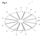
Figure 1] Figure 1 is a perspective view of a microneedle device in accordance with a first embodiment. - [
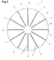
Figure 2] Figure 2 is a plan view of the microneedle device shown inFigure 1 . - [
Figure 3] Figure 3 is a bottom view of the microneedle device shown inFigure 1 . - [
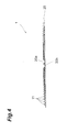
Figure 4] Figure 4 is a side view of the microneedle device shown inFigure 1 . - [
Figure 5] Figure 5 shows directions of tips of microneedles shown inFigure 1 - [
Figure 6] Figure 6 shows a state where the microneedle device is placed on skin. - [
Figure 7] Figure 7 schematically shows a state where a microneedle is in contact with skin. - [
Figure 8] Figure 8 shows a case of turning the microneedle device placed on skin. - [
Figure 9] Figure 9 schematically shows a state where the microneedle is stuck into skin. - [
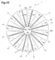
Figure 10] Figure 10 shows turn of the microneedle device. - [
Figure 11] Figure 11 is a plan view of one aspect of a microneedle device in accordance with a second embodiment. - [
Figure 12] Figure 12 is a plan view of another aspect of the microneedle device in accordance with the second embodiment. - [
Figure 13] Figure 13 is a plan view of yet another aspect of the microneedle device in accordance with the second embodiment. - [
Figure 14] Figure 14 is a plan view of yet another aspect of the microneedle device in accordance with the second embodiment. - [
Figure 15] Figure 15 is a plan view of yet another aspect of the microneedle device in accordance with the second embodiment. - [
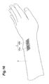
Figure 16] Figure 16 shows a state where the microneedle device are placed on skin. - [
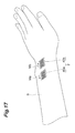
Figure 17] Figure 17 shows a case of moving the microneedle device placed on the skin parallel to itself. - [
Figure 18] Figure 18 is a plan view of a microneedle device in accordance with a variation. - [
Figure 19] Figure 19 is a plan view of a microneedle device in accordance with another variation. - [
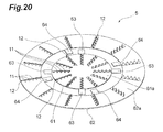
Figure 20] Figure 20 is a perspective view of a microneedle device in accordance with yet another variation. - [
Figure 21] Figure 21 is a perspective view of a microneedle device in accordance with yet another variation. - Hereinafter, the embodiments of the present invention are described with reference to accompanying drawings. In description of the drawings, the same or similar element is designated by the same reference numeral without duplicated description on the element.
- With reference to
Figures 1 to 5 , a structure of amicroneedle array 10 in accordance with the first embodiment will be described. Themicroneedle array 10 is a set of a plurality ofmicroneedles 11 to be stuck into skin, and is arranged on an arbitrary support face. In the present embodiment, themicroneedle array 10 is a part of a sheet-like microneedle device 1. - The
microneedle device 1 is a tool for transdermally administering an active ingredient by puncturing skin. Themicroneedle device 1 is completed by cutting acircular sheet 20 to form a large number ofmicroneedles 11 and by erecting themicroneedles 11 in an oblique direction from a sheet face. As shown inFigure 4 , all of themicroneedles 11 are erected on a principal face (support face) 20a. Any acute angle is applicable to an angle (or an inclination angle) between each of themicroneedles 11 and theprincipal face 20a. Theprincipal face 20a faces skin when themicroneedle device 1 is used. Aback face 20b of thesheet 20 is the back of theprincipal face 20a, and a finger or any auxiliary tool touches theback face 20b for puncture when themicroneedle device 1 is used. - Material of the
sheet 20 and themicroneedles 11 is not limited. For example, thesheet 20 and themicroneedles 11 may be made from any one of stainless steel, polyethylene terephthalate (PET), another metal, another resin, biodegradable material, ceramic, and bioabsorbable material. Alternatively, thesheet 20 and themicroneedles 11 may be made from a combination of the materials. - It is possible to form the
microneedle array 10 by etching. If a sheet is metal, it is possible to form themicroneedle array 10 by etching the sheet with a chemical solution to form a large number ofmicroneedles 11 and by erecting themicroneedles 11 in an oblique direction. If a sheet is non-metal, the sheet may be cut with a laser to form a large number ofmicroneedles 11, and themicroneedles 11 may be erected as with the case of a metal sheet. If etching is used as above, a void is generated around each of themicroneedles 11. As a matter of course, themicroneedle array 10 may be formed by any method other than etching. - Dimensions of the
sheet 20 are not limited, and may be optionally set depending on an intended purpose or a usage portion. For example, a lower limit of a diameter of thesheet 20 is determined in consideration of a dose of an active ingredient, and an upper limit of the diameter is determined in consideration of a size of a biological body. For example, the lower limit of the diameter may be 0.1 cm or 1 cm, and the upper limit of the diameter may be 60 cm, 50 cm, 30 cm or 20 cm. In the present embodiment, since themicroneedles 11 are formed by cutting thesheet 20, the thickness of thesheet 20 is determined in consideration of puncture performance of themicroneedles 11. For example, a lower limit of the thickness may be 5 µm or 20 µm, and an upper limit of the thickness may be 1000 µm or 300 µm. - Parameters related to the microneedle 11 are also not limited. For example, a lower limit of the length of the
microneedles 11 may be 10 µm or 100 µm, and an upper limit of the length may be 10000 µm or 1000 µm. Here, the length of the microneedle 11 is a distance from the base (a root of a portion erected from theprincipal face 20a) of the microneedle 11 to an apex thereof. As described above, in the present embodiment, the thickness of the microneedle 11 depends on the thickness of thesheet 20. A lower limit of density of the microneedle 11 may be 0.05 piece/cm2 or 1 piece/cm2, and an upper limit of the density may be 10000 pieces/cm2, or 5000 pieces/cm2. The lower limit of the density is a value calculated in terms of the number of needles and area thereof capable of administering 1 mg of an active ingredient, and the upper limit of the density is a limit value in consideration of a shape of the needle. - As shown in
Figures 1 to 3 , themicroneedle array 10 is a set of a plurality oflines 12 each of which extends along a radial direction of thesheet 20. Each of thelines 12 is composed of the plurality ofmicroneedles 11. The plurality oflines 12 extends radially from near the center of thesheet 20. In the present embodiment, although every angle between two lines adjacent to each other is 30°, the angle is not limited. For example, the angle may be 10°, 15°, 45°, 60°, 90°, 120°, or 180°. In addition, the angle may not be uniform. - When the whole of the
microneedle array 10 is viewed, directions in which all of themicroneedles 11 point are unified into a clockwise direction or a counterclockwise direction. In the present embodiment, when themicroneedle device 1 is viewed from theback face 20b, themicroneedle array 10 points in the clockwise direction as a whole. All tips of the plurality ofmicroneedles 11 in oneline 12 point in the same direction. Each of arrows Da to D1 shown inFigure 5 shows a tip direction of themicroneedles 11 of each of thelines 12. As can be seen from the arrows, with respect to any two lines, a direction (first direction) in which a tip of each of the microneedles (first microneedles) 11 in one line (first line) 12 points is different from a direction (second direction) in which a tip of each of the microneedles (second microneedles) 11 in the other line (second line) 12 points. There may be at least one pair of two lines in which a tip direction of themicroneedles 11 is different from each other, and thus, with respect to a specific plurality of lines, a tip direction of themicroneedles 11 may be the same. - The length of the
microneedles 11 in themicroneedle array 10 may not be uniform. For example, the microneedle 11 positioned in a center portion of thesheet 20 may be longer than the microneedle 11 positioned in a peripheral portion of thesheet 20. As a further variation of this type, in each of thelines 12, each of themicroneedles 11 may be formed so that the microneedle 11 gradually increases in length from the peripheral portion of thesheet 20 to the center portion thereof. Alternatively, the microneedle 11 positioned in the center portion of thesheet 20 may be shorter than the microneedle 11 positioned in the peripheral portion of thesheet 20. As a further variation of this type, in each of thelines 12, each of themicroneedles 11 may be formed so that the microneedle 11 gradually decreases in length from the peripheral portion of thesheet 20 to the center portion thereof. - In the
microneedle array 10, an angle (or an inclination angle) between the microneedle 11 and theprincipal face 20a may not be uniform. For example, the microneedle 11 positioned in the center portion of thesheet 20 may have an inclination angle larger than that of the microneedle 11 positioned in the peripheral portion of thesheet 20. As a further variation of this type, in each of thelines 12, each of themicroneedles 11 may be formed so that the inclination angle of the microneedle 11 gradually increases from the peripheral portion of thesheet 20 to the center portion thereof. If the length of each of themicroneedles 11 is allowed to be different as described above, an inclination angle of each of themicroneedles 11 may be set so that height of each of themicroneedles 11 is the same or almost the same. Here, the height of the microneedle 11 is a distance from theprincipal face 20a to the apex of themicroneedle 11. - In the
microneedle array 10, both of a length and an inclination angle of the microneedle 11 may not be uniform. For example, a length and an inclination angle of the microneedle 11 positioned in the center portion of thesheet 20 is larger than those of the microneedle 11 positioned in the peripheral portion of thesheet 20. As a further variation of this type, in each of thelines 12, each of themicroneedles 11 may be formed so that the length and the inclination angle of the microneedle 11 gradually increase from the peripheral portion of thesheet 20 to the center portion thereof. Alternatively, the microneedle 11 positioned in the center portion of thesheet 20 may have a length shorter as well as an inclination angle larger than those of the microneedle 11 positioned in the peripheral portion of thesheet 20. As a further variation of this type, in each of thelines 12, each of themicroneedles 11 may be formed so that the inclination angle of the microneedle 11 gradually increases from the peripheral portion of thesheet 20 to the center portion thereof while the length thereof decreases. - As with the example described above, a length or an inclination angle between the microneedle 11 in the peripheral portion of the
sheet 20 and the microneedle 11 in the center portion of thesheet 20 is changed to allow the microneedle 11 positioned in the center portion of thesheet 20 to be reliably stuck into skin. - A tip of each of the
microneedles 11 may point in a tangential direction of a virtual circle, which shows a turning direction of themicroneedles 11. The example shown inFigures 2 and3 is one aspect of that type. Alternatively, the tip of each of themicroneedles 11 may point in a direction that is closer to the center of thesheet 20 than the tangential direction. In this case, it is possible to reduce resistance to be applied to each of themicroneedles 11 at the time of puncture. - Next, with reference to
Figures 6 to 10 , a method of use of themicroneedle device 1 will be described. - A preparation method of an active ingredient at the time of using the
microneedle device 1 is not limited. For example, the following is considered as the preparation method: a method of applying coating of an active ingredient to themicroneedle device 1 itself in advance; a method of applying an active ingredient to skin before themicroneedle device 1 is placed on the skin; and a method of applying an active ingredient to skin after themicroneedle device 1 is punctured into the skin. The coating may be performed by using a principle of screen printing or by another method. In a case where a biodegradable sheet is used, it is possible to allow the sheet itself to contain an active ingredient. Alternatively, a reservoir or a gel, containing the active ingredient, may be provided on theback face 20b. In addition, after or during puncture, a medication may be delivered intradermally by using energy, such as spring, pressure, electricity, and magnetism. - First, while pointing the
principal face 20a to skin S, a user places themicroneedle device 1 on the skin to bring a tip of each of themicroneedles 11 into contact with the skin S as shown inFigures 6 and7 . Hereinafter, a point at which themicroneedle 11 is in contact with the skin S is referred to as a "contact point". - Subsequently, as shown in
Figure 8 , the user presses theback face 20b to press themicroneedle device 1 into the skin while turning themicroneedle device 1 in a direction D in which the tip of the microneedle 11 points. The turning and pressing allow each of themicroneedles 11 to be stuck into the skin S from a contact point C as shown inFigure 9 while turning along a surface of the skin S. At this time, the contact point C is displaced by a distance A as shown inFigure 9 , and this means that the skin S in the periphery of the contact point C is stretched or shrunk. Thus, it can be said that each of themicroneedles 11 is stuck into the skin S while deforming the skin S by itself. - The user twists the
microneedle device 1 in this manner to enable an active ingredient to be administered into one's own body. Thus, themicroneedle device 1 can be referred to as a torsion type microneedle device. In addition, instead of removing themicroneedle device 1 from the skin immediately after puncture, the user may continue to press themicroneedle device 1 by hand or with an auxiliary tool such as a tape for a prescribed time with the state of puncturing maintained. - Since each of the
lines 12 extending radially is arranged in thesheet 20 away from each other by a predetermined angle, a direction of movement of the microneedle 11 at the time of turning themicroneedle device 1 is different for each of thelines 12. The difference is obvious because directions of motion vectors Va1, and Vb to V1 of therespective lines 12 inFigure 10 are different. In addition, since thesheet 20 is turned, a distance of movement of each of themicroneedles 11 in oneline 12 is different from each other. The difference is obvious because the length of a motion vector of each of the microneedles 11 (inFigure 10 , only motion vectors Va1 to Va7 are shown) in oneline 12 inFigure 10 is different, for example. In this way, since a direction or distance of movement is different for each contact point C, skin in an area where themicroneedle device 1 is applied is partially stretched or partially shrunk. In any case, when themicroneedle device 1 is applied to skin, the skin in an application area thereof is deformed as a whole by each of themicroneedles 11. - As described above, according to the present embodiment, since each of the
microneedles 11 pointing a different direction is moved along a tip direction of each of themicroneedles 11, a direction of movement of the microneedle 11 is different between a portion with which the microneedle 11 in oneline 12 is in contact and a portion with which the microneedle 11 in anotherline 12 is in contact. In addition, since themicroneedles device 1 in a circular shape is turned to perform puncture, a distance of movement of each of themicroneedles 11 in oneline 12 extending along a radial direction of themicroneedle device 1 is different from each other. This kind of difference in a direction or distance causes skin to be deformed, so that themicroneedles 11 are stuck into the skin deformed. In this way, since themicroneedles 11 themselves deform the skin, another member or mechanism for achieving the deformation is unnecessary, whereby it is possible to reduce a puncture device in size accordingly. - With reference to
Figures 11 to 15 , a structure of amicroneedle array 30 in accordance with a second embodiment will be described. In the present embodiment, themicroneedle array 30 is a part of a sheet-like microneedle device 2. Hereinafter, a matter different from that of the first embodiment will be described in particular. - As shown in
Figures 11 to 15 , amicroneedle device 2 in the present embodiment comprises a set of tworectangular sheets sheet 40a corresponds to the first support face and a principal face of asheet 40b corresponds to the second support face, these two principal faces (support faces) are independent of each other. - Each of the
sheets microneedles 11 formed by a method as with the first embodiment. Themicroneedle array 30 in the present embodiment is a set of a plurality ofmicroneedles 11a on thesheet 40a and a plurality ofmicroneedles 11b on thesheet 40b. In each of thesheets microneedles 11 arranged in two dimensions point in the same direction. However, when themicroneedle device 2 is used, the microneedles (first microneedles) 11a and the microneedles (second microneedles) 11b point in a different direction from each other. - Dimensions of each of the
sheets sheets sheets sheets microneedles 11, as with the first embodiment. - With respect to a position relationship between the
sheet 40a and thesheet 40b, various aspects can be thought in consideration of a direction (slide direction) of movement of each of the twosheets - In an example shown in
Figure 11 , thesheets microneedles 11a and themicroneedles 11b are arranged back to back. That is, a direction Ma of a tip of each of themicroneedles 11a and a direction Mb of a tip of each of themicroneedles 11b are different from each other by 180 degrees. Since each of thesheets sheet 40a as well as the direction Mb is also a direction of movement of thesheet 40b. In this example, each of the twosheets sheets - In an example shown in
Figure 12 , thesheets microneedles 11 a and themicroneedles 11b face each other. That is, a direction Ma of a tip of each of themicroneedles 11a (a direction of movement of thesheet 40a) and a direction Mb of a tip of each of themicroneedles 11b (a direction of movement of thesheet 40b) are different from each other by 180 degrees. In this example, each of the twosheets sheets - In an example shown in
Figure 13 , thesheets microneedles 11a and an axis Xb along a tip direction Mb of each of themicroneedles 11b intersect each other. An angle between the two movement axes Xa and Xb is more than 0° and less than 180°. In this example, the twosheets sheet 40a and thesheet 40b move away from each other. - Even in an example shown in
Figure 14 , thesheets sheet 40a and the movement axis Xb of thesheet 40b intersect each other. An angle between the two movement axes Xa and Xb is more than 0° and less than 180°. In this example, the twosheets sheet 40a and thesheet 40b approach each other. - Even in an example shown in
Figure 15 , thesheets sheet 40a and the movement axis Xb of thesheet 40b intersect each other. An angle between the movement axis Xa of thesheet 40a and the movement axis Xb of thesheet 40b is more than 0° and less than 180°. In this example, thesheet 40a is moved so as to approach an initial position of thesheet 40b, and thesheet 40b is moved so as to move away from an initial position of thesheet 40a. - In the examples of
Figures 11 to 15 , although the twosheets - The
microneedle device 2 may be composed of only the twosheets Figures 11 to 15 when used. As shown inFigures 12 and14 , in a case where the twosheets microneedles 11, themicroneedle device 2 may be composed of the twosheets microneedle device 2 may comprise any support member (such as a rail for allowing thesheets sheets Figures 11 to 15 . - Next, with reference to
Figures 16 and17 , a method of use of themicroneedle device 2 will be described. Hereinafter, an example in which a user oneself moves themicroneedle device 2 shown inFigure 11 with one's finger will be described. - First, as shown in
Figure 16 , while pointing the principal face (a face from which themicroneedles 11 protrude) of the twosheets microneedle device 2 on the skin to bring a tip of each of themicroneedles 11 into contact with the skin S. - Subsequently, as shown in
Figure 17 , while pressing a back face of each of thesheets sheet 40a in the direction Ma and thesheet 40b in the direction Mb, along a surface of the skin S, the user presses the twosheets sheets microneedles 11 is stuck into the skin S while deforming the skin S near a contact point. - Even the present embodiment can get an effect as with the first embodiment above. Specifically, since each of the
microneedles microneedles 11 is stuck into skin while deforming the skin. In this way, since themicroneedles 11 themselves deform the skin, another member or mechanism for achieving the deformation is unnecessary, whereby it is possible to reduce a puncture device in size accordingly. - However, in order to perform puncture with the microneedle arrays independent of each other such as the second embodiment (refer to
Figure 11 and so on), a distance for allowing each of the microneedle arrays to be moved on skin is required. In contrast, the microneedle array of the first embodiment (Figure 1 ) only turns on skin, so that an additional space for movement is unnecessary. That is, the microneedle array (a torsion type microneedle array) of the first embodiment is further suitable for downsizing. In addition, as compared with the microneedle array of the second embodiment, the microneedle array of the first embodiment is allowed to be punctured with even less force. - The present invention has been described in detail on the basis of its embodiments. However, the present invention is not limited to the embodiments above. The present invention may include various variations within a range without departing from the essence of the present invention.
- With respect to each of the embodiments above, a shape of the line of the
microneedles 11 is not limited to a linear shape, and may be optionally determined. For example, in a microneedle device 3 (amicroneedle array 10A) shown inFigure 18 , a plurality oflines 12A extends radially from near the center of thesheet 20 as well as each of thelines 12A is formed in an arc shape. In the example ofFigure 18 , each arc is convex in a clockwise direction. - With respect to each of the embodiments above, a shape of the sheet is not limited to a circle and a rectangle, may be any shape such as a square, a star, an ellipse, and another polygon. An aspect of the microneedle array (arrangement of the microneedles 11) can be optionally determined depending on a shape of the sheet. For example, a
microneedle device 4 shown inFigure 19 is formed by using asquare sheet 50. In the example, if somelines 12 in which a tip direction of themicroneedles 11 is the same are indicated as one group, it can be said that amicroneedle array 10B is a set of four groups whose tip directions are different from each other by 90°. InFigure 19 , although themicroneedle array 10B points in a counterclockwise direction as a whole, the direction may be clockwise. A difference in a tip direction of each group is not limited to 90°, and may be set at any angle. - Even in the
microneedle devices microneedles 11 may be different from each other as with the first embodiment. - In the second embodiment above, although the
microneedle array 30 is composed of themicroneedles 11 in two sheets, the microneedle array may be composed of microneedles in three or more sheets. - A microneedle array such as shown in
Figure 20 is also one aspect of the present invention. The microneedle array is a part of a microneedle device 5. - The microneedle device 5 comprises a set of a circular
inner sheet 61 and ring-shaped (donut-shaped)outer sheet 62. Thus, a principal face (first support face) 61a of theinner sheet 61 and a principal face (second support face) 62a of theouter sheet 62 are independent of each other. Since an inner diameter of theouter sheet 62 is larger than an outer diameter of theinner sheet 61, it is possible to fit theinner sheet 61 inside theouter sheet 62. In an outer periphery portion of theinner sheet 61, there is provided a plurality ofprotrusions 63 extending radially outward. In an inner periphery portion of theouter sheet 62, there is provided a plurality ofprotrusions 64 extending radially inward. Oneprotrusion 64 corresponds to oneprotrusion 63. When the microneedle device 5 is used, ones of theprotrusions protrusions sheets Figure 20 , although each of the fourprotrusions protrusions protrusions protrusions - Each of the
inner sheet 61 and theouter sheet 62 comprises a large number ofmicroneedles 11 formed by a method as with the first embodiment. A microneedle array in the microneedle device 5 is a set of the plurality ofmicroneedles 11 on theinner sheet 61 and the plurality ofmicroneedles 11 on theouter sheet 62. In both of theinner sheet 61 and theouter sheet 62, the plurality ofmicroneedles 11 is arranged as with the first embodiment above. That is, in each of thesheets lines 12 that is a set of themicroneedles 11 extends radially, and directions in which all of themicroneedles 11 in both of thesheets microneedles 11 may not be uniform, and the length or the inclination angle of each of themicroneedles 11 may be different from each other as with the first embodiment. - When the microneedle device 5 is used, a user first places the microneedle device 5 on the skin while pointing principal faces (support faces) 61a and 62a from which the
microneedles 11 protrude to skin. At the time, with reference to a turning direction of thesheets 61 and 62 (a direction in which themicroneedles 11 point), thesheets protrusion 64 is positioned in front of theprotrusion 63 in each set of theprotrusions protrusions - Subsequently, the user turns the
inner sheet 61 while pressing it toward the skin. By means of this operation, each of themicroneedles 11 on theinner sheet 61 is stuck into the skin while deforming the skin. In addition, theprotrusions 63 provided in theinner sheet 61 are brought into contact with therespective protrusions 64 to push theprotrusions 64 along a turning direction, whereby theouter sheet 62 is also turned. As a result, each of themicroneedles 11 on theouter sheet 62 is stuck into the skin while deforming the skin. In this way, in a case where the microneedle device 5 is used, after the microneedles on the inner sheet 61 (the microneedles positioned on the first support face) 11 start to turn, the microneedles on the outer sheet 62 (the microneedles positioned in the second support face positioned outside the first support face) 11 start to turn. In the each set, an initial gap between theprotrusions - In a case where such the microneedle device 5 is used, it is possible to reliably stick the microneedles positioned on a center side of the device into skin.
- Even in the microneedle device 5, each line of the microneedles may be formed in an arc shape as with the
microneedle device 3. - The principal face (support face) from which the microneedles protrude may be convex, and a microneedle array including such a structure is also one aspect of the present invention. Here, the term "the support face is convex" means that a central portion of the support face rises. Although this definition includes an aspect in which the support face is a side face of a cone and an aspect in which the support face is a hemisphere face, an aspect in which the support face is convex is not limited to the aspects above. In addition, parameters defining a convex are not limited, and a center angle of a cone and a curvature of a hemisphere, for example, may be optionally determined.
-
Figure 21 shows an example in which a support face is convex. A microneedle array shown inFigure 21 is a part of amicroneedle device 6. - The
microneedle device 6 can be acquired by forming a large number ofmicroneedles 11 on asheet 70 in a corn shape. Thus, a principal face (support face) 70a from which themicroneedles 11 protrude is a side face of a cone. It is possible to form themicroneedles 11 by a method as with the first embodiment. A microneedle array in themicroneedle device 6 is a set of a plurality oflines 12 each of which extends along a generatrix of thesheet 70. Each of thelines 12 is composed of the plurality ofmicroneedles 11. Directions in which all of themicroneedles 11 point are unified into a clockwise or counterclockwise direction. An angle between two lines adjacent to each other may be optionally set. A length and an inclination angle of each of themicroneedles 11 may not be uniform, and the length or the inclination angle of each of themicroneedles 11 may be different from each other as with the first embodiment. - When the
microneedle device 6 is used, a user first places themicroneedle device 6 on skin while pointing theprincipal face 70a to the skin. Subsequently, the user presses themicroneedle device 6 into the skin while turning themicroneedle device 6 in a direction in which a tip of the microneedle 11 points. By means of this operation, each of themicroneedles 11 is stuck into the skin while deforming the skin. - Even in the
microneedle device 6, each line of the microneedles may be formed in an arc shape as with themicroneedle device 3. - Although the microneedle is formed in a triangular shape in each of the embodiments above, a shape of the microneedle is not limited if capable of puncture. In addition, the microneedle may not be a planar shape that can be acquired by cutting out a sheet, and may be a three-dimensional shape such as a cone and a pyramid.
- In each of the embodiments above, although the microneedle array is supported by a sheet-like member, the microneedle array may be formed on any face.
- 1 to 6 ... microneedle device, 10, 10A, 10B, 30 ... microneedle array, 11, 11 a, 11b ... microneedle, 12, 12A ... line of microneedles, 20, 40a, 40b, 50, 70 ... sheet, 61 ... inner sheet, 62 ... outer sheet, 20a, 61a, 62a, 70a ... principal face (support face), 20b ... back face.
Claims (11)
- A microneedle array comprising
at least a first microneedle and a second microneedle that are inclined with respect to a support face, wherein
a tip of the first microneedle points in a first direction and a tip of the second microneedle points in a second direction different from the first direction, and wherein
the first microneedle in contact with skin is stuck into the skin while moving in the first direction along a surface of the skin, and the second microneedle in contact with the skin is stuck into the skin while moving in the second direction along the surface of the skin. - The microneedle array according to Claim 1, wherein each of the first microneedle and the second microneedles is stuck into the skin while rotationally moved.
- The microneedle array according to Claim 2, further comprising:a first line including at least the one first microneedle; anda second line including at least the one second microneedle, whereinthe first line and the second line may extend radially.
- The microneedle array according to Claim 3, wherein each of the first line and the second line is arranged along an arc.
- The microneedle array according to Claim 3 or 4, wherein a microneedle positioned in a center portion of the support face is longer than a microneedle positioned in a peripheral portion of the support face.
- The microneedle array according to Claim 3 or 4, wherein a microneedle positioned in the center portion of the support face is shorter than a microneedle positioned in the peripheral portion of the support face.
- The microneedle array according to any one of Claims 3 to 6, wherein an inclination angle of a microneedle positioned in the center portion of the support face is larger than an inclination angle of a microneedle positioned in the peripheral portion of the support face.
- The microneedle array according to any one of Claims 2 to 7, wherein
the support face includes a first support face and a second support face positioned outside the first support face, and
after a microneedle positioned in the first support face starts to be rotationally moved, a microneedle positioned in the second support face starts to be rotationally moved. - The microneedle array according to any one of Claims 2 to 7, wherein the support face is convex.
- The microneedle array according to Claim 1, wherein the first microneedle is provided in the first support face and the second microneedle is provided in the second support face independent of the first support face, and wherein the first support face is moved in the first direction and the second support face is moved in the second direction.
- The microneedle array according to Claim 10, wherein the first support face and the second support face are moved parallel to themselves.
Applications Claiming Priority (2)
| Application Number | Priority Date | Filing Date | Title |
|---|---|---|---|
| JP2013025586 | 2013-02-13 | ||
| PCT/JP2014/053186 WO2014126101A1 (en) | 2013-02-13 | 2014-02-12 | Microneedle array |
Publications (3)
| Publication Number | Publication Date |
|---|---|
| EP2957315A1 true EP2957315A1 (en) | 2015-12-23 |
| EP2957315A4 EP2957315A4 (en) | 2016-10-19 |
| EP2957315B1 EP2957315B1 (en) | 2019-11-13 |
Family
ID=51354100
Family Applications (1)
| Application Number | Title | Priority Date | Filing Date |
|---|---|---|---|
| EP14751051.5A Active EP2957315B1 (en) | 2013-02-13 | 2014-02-12 | Microneedle array |
Country Status (5)
| Country | Link |
|---|---|
| US (1) | US9717893B2 (en) |
| EP (1) | EP2957315B1 (en) |
| JP (1) | JP6387338B2 (en) |
| TW (1) | TWI594783B (en) |
| WO (1) | WO2014126101A1 (en) |
Families Citing this family (6)
| Publication number | Priority date | Publication date | Assignee | Title |
|---|---|---|---|---|
| CN106999702B (en) * | 2014-12-05 | 2020-07-10 | 久光制药株式会社 | Microneedle device system |
| JP6724792B2 (en) * | 2015-01-13 | 2020-07-15 | 凸版印刷株式会社 | Transdermal administration device |
| EP3508247B1 (en) * | 2016-09-01 | 2024-08-14 | Hisamitsu Pharmaceutical Co., Inc. | Microneedle sheet |
| KR20190005478A (en) * | 2017-07-07 | 2019-01-16 | 경상대학교산학협력단 | Microneedle device |
| KR102119675B1 (en) * | 2017-12-11 | 2020-06-05 | 랩앤피플주식회사 | High density micro-needle |
| JP7689708B2 (en) * | 2019-06-25 | 2025-06-09 | コスメディ製薬株式会社 | Microneedle array with non-uniform needle density |
Family Cites Families (12)
| Publication number | Priority date | Publication date | Assignee | Title |
|---|---|---|---|---|
| CA2265906C (en) | 1996-09-17 | 2003-11-11 | Deka Products Limited Partnership | System for delivery of drugs by transport |
| WO1999029364A1 (en) | 1997-12-11 | 1999-06-17 | Alza Corporation | Device for enhancing transdermal agent flux |
| US6743211B1 (en) | 1999-11-23 | 2004-06-01 | Georgia Tech Research Corporation | Devices and methods for enhanced microneedle penetration of biological barriers |
| US6623457B1 (en) | 1999-09-22 | 2003-09-23 | Becton, Dickinson And Company | Method and apparatus for the transdermal administration of a substance |
| ATE310561T1 (en) | 1999-12-10 | 2005-12-15 | Alza Corp | APPARATUS AND METHOD FOR IMPROVING MICRONEEDLE SKIN PIERCING |
| US6537242B1 (en) | 2000-06-06 | 2003-03-25 | Becton, Dickinson And Company | Method and apparatus for enhancing penetration of a member for the intradermal sampling or administration of a substance |
| US20040087992A1 (en) * | 2002-08-09 | 2004-05-06 | Vladimir Gartstein | Microstructures for delivering a composition cutaneously to skin using rotatable structures |
| WO2004019777A2 (en) * | 2002-08-29 | 2004-03-11 | Becton Dickinson And Company | Substance delivery via rotating mocroabrading surface |
| US20060253079A1 (en) | 2005-04-25 | 2006-11-09 | Mcdonough Justin | Stratum corneum piercing device |
| CN101829396B (en) | 2009-03-27 | 2013-01-30 | 清华大学 | Micro-needle array chip and percutaneous administration patch using same and preparation method thereof |
| JP2012055343A (en) * | 2010-09-03 | 2012-03-22 | Toray Eng Co Ltd | Microneedle sheet and method for manufacturing the same |
| KR101252746B1 (en) * | 2010-10-21 | 2013-04-11 | 채희중 | Skin Stimulating Stamp |
-
2014
- 2014-02-12 WO PCT/JP2014/053186 patent/WO2014126101A1/en not_active Ceased
- 2014-02-12 EP EP14751051.5A patent/EP2957315B1/en active Active
- 2014-02-12 JP JP2015500255A patent/JP6387338B2/en active Active
- 2014-02-12 US US14/767,138 patent/US9717893B2/en active Active
- 2014-02-13 TW TW103104723A patent/TWI594783B/en active
Also Published As
| Publication number | Publication date |
|---|---|
| EP2957315B1 (en) | 2019-11-13 |
| EP2957315A4 (en) | 2016-10-19 |
| JPWO2014126101A1 (en) | 2017-02-02 |
| US20150374967A1 (en) | 2015-12-31 |
| WO2014126101A1 (en) | 2014-08-21 |
| JP6387338B2 (en) | 2018-09-05 |
| TW201519924A (en) | 2015-06-01 |
| TWI594783B (en) | 2017-08-11 |
| US9717893B2 (en) | 2017-08-01 |
Similar Documents
| Publication | Publication Date | Title |
|---|---|---|
| EP2957315B1 (en) | Microneedle array | |
| JP7082230B2 (en) | Microneedle array unit and container | |
| KR102101522B1 (en) | Microneedle sheet | |
| EP1531896B1 (en) | Microprotrusion arrays and methods for using same to deliver substances into tissue | |
| EP1904158B1 (en) | Collapsible patch with microneedle array | |
| CN105916543B (en) | Microneedle unit and microneedle assembly | |
| EP3725359B1 (en) | Storage container, microneedle unit, storage container group, and method of producing microneedle unit | |
| JP6074889B2 (en) | Micro needle tip | |
| CN103170055B (en) | Microneedle array applicator and the method for discharging microneedle array | |
| JP6658524B2 (en) | Microneedle and microneedle assembly | |
| JP6662296B2 (en) | Needle assembly for transdermal administration and method of manufacturing the same | |
| KR20160052590A (en) | Micro-needle sheet | |
| JP6193409B2 (en) | applicator | |
| JP2016131619A (en) | Transdermal administration device | |
| KR20190089951A (en) | Applicator | |
| WO2017014129A1 (en) | Percutaneous administration device | |
| JP6975865B2 (en) | Microneedle array unit | |
| JP2019180587A (en) | Needle like body device |
Legal Events
| Date | Code | Title | Description |
|---|---|---|---|
| PUAI | Public reference made under article 153(3) epc to a published international application that has entered the european phase |
Free format text: ORIGINAL CODE: 0009012 |
|
| 17P | Request for examination filed |
Effective date: 20150908 |
|
| AK | Designated contracting states |
Kind code of ref document: A1 Designated state(s): AL AT BE BG CH CY CZ DE DK EE ES FI FR GB GR HR HU IE IS IT LI LT LU LV MC MK MT NL NO PL PT RO RS SE SI SK SM TR |
|
| AX | Request for extension of the european patent |
Extension state: BA ME |
|
| DAX | Request for extension of the european patent (deleted) | ||
| A4 | Supplementary search report drawn up and despatched |
Effective date: 20160920 |
|
| RIC1 | Information provided on ipc code assigned before grant |
Ipc: A61M 37/00 20060101AFI20160914BHEP |
|
| GRAP | Despatch of communication of intention to grant a patent |
Free format text: ORIGINAL CODE: EPIDOSNIGR1 |
|
| STAA | Information on the status of an ep patent application or granted ep patent |
Free format text: STATUS: GRANT OF PATENT IS INTENDED |
|
| INTG | Intention to grant announced |
Effective date: 20190626 |
|
| GRAS | Grant fee paid |
Free format text: ORIGINAL CODE: EPIDOSNIGR3 |
|
| GRAA | (expected) grant |
Free format text: ORIGINAL CODE: 0009210 |
|
| STAA | Information on the status of an ep patent application or granted ep patent |
Free format text: STATUS: THE PATENT HAS BEEN GRANTED |
|
| AK | Designated contracting states |
Kind code of ref document: B1 Designated state(s): AL AT BE BG CH CY CZ DE DK EE ES FI FR GB GR HR HU IE IS IT LI LT LU LV MC MK MT NL NO PL PT RO RS SE SI SK SM TR |
|
| REG | Reference to a national code |
Ref country code: AT Ref legal event code: REF Ref document number: 1201037 Country of ref document: AT Kind code of ref document: T Effective date: 20191115 Ref country code: CH Ref legal event code: EP |
|
| REG | Reference to a national code |
Ref country code: DE Ref legal event code: R096 Ref document number: 602014056764 Country of ref document: DE |
|
| REG | Reference to a national code |
Ref country code: IE Ref legal event code: FG4D |
|
| REG | Reference to a national code |
Ref country code: NL Ref legal event code: MP Effective date: 20191113 |
|
| REG | Reference to a national code |
Ref country code: LT Ref legal event code: MG4D |
|
| PG25 | Lapsed in a contracting state [announced via postgrant information from national office to epo] |
Ref country code: NL Free format text: LAPSE BECAUSE OF FAILURE TO SUBMIT A TRANSLATION OF THE DESCRIPTION OR TO PAY THE FEE WITHIN THE PRESCRIBED TIME-LIMIT Effective date: 20191113 Ref country code: PL Free format text: LAPSE BECAUSE OF FAILURE TO SUBMIT A TRANSLATION OF THE DESCRIPTION OR TO PAY THE FEE WITHIN THE PRESCRIBED TIME-LIMIT Effective date: 20191113 Ref country code: BG Free format text: LAPSE BECAUSE OF FAILURE TO SUBMIT A TRANSLATION OF THE DESCRIPTION OR TO PAY THE FEE WITHIN THE PRESCRIBED TIME-LIMIT Effective date: 20200213 Ref country code: FI Free format text: LAPSE BECAUSE OF FAILURE TO SUBMIT A TRANSLATION OF THE DESCRIPTION OR TO PAY THE FEE WITHIN THE PRESCRIBED TIME-LIMIT Effective date: 20191113 Ref country code: LT Free format text: LAPSE BECAUSE OF FAILURE TO SUBMIT A TRANSLATION OF THE DESCRIPTION OR TO PAY THE FEE WITHIN THE PRESCRIBED TIME-LIMIT Effective date: 20191113 Ref country code: NO Free format text: LAPSE BECAUSE OF FAILURE TO SUBMIT A TRANSLATION OF THE DESCRIPTION OR TO PAY THE FEE WITHIN THE PRESCRIBED TIME-LIMIT Effective date: 20200213 Ref country code: GR Free format text: LAPSE BECAUSE OF FAILURE TO SUBMIT A TRANSLATION OF THE DESCRIPTION OR TO PAY THE FEE WITHIN THE PRESCRIBED TIME-LIMIT Effective date: 20200214 Ref country code: LV Free format text: LAPSE BECAUSE OF FAILURE TO SUBMIT A TRANSLATION OF THE DESCRIPTION OR TO PAY THE FEE WITHIN THE PRESCRIBED TIME-LIMIT Effective date: 20191113 Ref country code: SE Free format text: LAPSE BECAUSE OF FAILURE TO SUBMIT A TRANSLATION OF THE DESCRIPTION OR TO PAY THE FEE WITHIN THE PRESCRIBED TIME-LIMIT Effective date: 20191113 Ref country code: PT Free format text: LAPSE BECAUSE OF FAILURE TO SUBMIT A TRANSLATION OF THE DESCRIPTION OR TO PAY THE FEE WITHIN THE PRESCRIBED TIME-LIMIT Effective date: 20200313 |
|
| PG25 | Lapsed in a contracting state [announced via postgrant information from national office to epo] |
Ref country code: RS Free format text: LAPSE BECAUSE OF FAILURE TO SUBMIT A TRANSLATION OF THE DESCRIPTION OR TO PAY THE FEE WITHIN THE PRESCRIBED TIME-LIMIT Effective date: 20191113 Ref country code: IS Free format text: LAPSE BECAUSE OF FAILURE TO SUBMIT A TRANSLATION OF THE DESCRIPTION OR TO PAY THE FEE WITHIN THE PRESCRIBED TIME-LIMIT Effective date: 20200313 Ref country code: HR Free format text: LAPSE BECAUSE OF FAILURE TO SUBMIT A TRANSLATION OF THE DESCRIPTION OR TO PAY THE FEE WITHIN THE PRESCRIBED TIME-LIMIT Effective date: 20191113 |
|
| PG25 | Lapsed in a contracting state [announced via postgrant information from national office to epo] |
Ref country code: AL Free format text: LAPSE BECAUSE OF FAILURE TO SUBMIT A TRANSLATION OF THE DESCRIPTION OR TO PAY THE FEE WITHIN THE PRESCRIBED TIME-LIMIT Effective date: 20191113 |
|
| PG25 | Lapsed in a contracting state [announced via postgrant information from national office to epo] |
Ref country code: ES Free format text: LAPSE BECAUSE OF FAILURE TO SUBMIT A TRANSLATION OF THE DESCRIPTION OR TO PAY THE FEE WITHIN THE PRESCRIBED TIME-LIMIT Effective date: 20191113 Ref country code: EE Free format text: LAPSE BECAUSE OF FAILURE TO SUBMIT A TRANSLATION OF THE DESCRIPTION OR TO PAY THE FEE WITHIN THE PRESCRIBED TIME-LIMIT Effective date: 20191113 Ref country code: RO Free format text: LAPSE BECAUSE OF FAILURE TO SUBMIT A TRANSLATION OF THE DESCRIPTION OR TO PAY THE FEE WITHIN THE PRESCRIBED TIME-LIMIT Effective date: 20191113 Ref country code: DK Free format text: LAPSE BECAUSE OF FAILURE TO SUBMIT A TRANSLATION OF THE DESCRIPTION OR TO PAY THE FEE WITHIN THE PRESCRIBED TIME-LIMIT Effective date: 20191113 Ref country code: CZ Free format text: LAPSE BECAUSE OF FAILURE TO SUBMIT A TRANSLATION OF THE DESCRIPTION OR TO PAY THE FEE WITHIN THE PRESCRIBED TIME-LIMIT Effective date: 20191113 |
|
| REG | Reference to a national code |
Ref country code: DE Ref legal event code: R097 Ref document number: 602014056764 Country of ref document: DE |
|
| REG | Reference to a national code |
Ref country code: AT Ref legal event code: MK05 Ref document number: 1201037 Country of ref document: AT Kind code of ref document: T Effective date: 20191113 |
|
| PG25 | Lapsed in a contracting state [announced via postgrant information from national office to epo] |
Ref country code: SK Free format text: LAPSE BECAUSE OF FAILURE TO SUBMIT A TRANSLATION OF THE DESCRIPTION OR TO PAY THE FEE WITHIN THE PRESCRIBED TIME-LIMIT Effective date: 20191113 Ref country code: SM Free format text: LAPSE BECAUSE OF FAILURE TO SUBMIT A TRANSLATION OF THE DESCRIPTION OR TO PAY THE FEE WITHIN THE PRESCRIBED TIME-LIMIT Effective date: 20191113 |
|
| PLBE | No opposition filed within time limit |
Free format text: ORIGINAL CODE: 0009261 |
|
| STAA | Information on the status of an ep patent application or granted ep patent |
Free format text: STATUS: NO OPPOSITION FILED WITHIN TIME LIMIT |
|
| REG | Reference to a national code |
Ref country code: CH Ref legal event code: PL |
|
| 26N | No opposition filed |
Effective date: 20200814 |
|
| GBPC | Gb: european patent ceased through non-payment of renewal fee |
Effective date: 20200213 |
|
| REG | Reference to a national code |
Ref country code: BE Ref legal event code: MM Effective date: 20200229 |
|
| PG25 | Lapsed in a contracting state [announced via postgrant information from national office to epo] |
Ref country code: LU Free format text: LAPSE BECAUSE OF NON-PAYMENT OF DUE FEES Effective date: 20200212 Ref country code: MC Free format text: LAPSE BECAUSE OF FAILURE TO SUBMIT A TRANSLATION OF THE DESCRIPTION OR TO PAY THE FEE WITHIN THE PRESCRIBED TIME-LIMIT Effective date: 20191113 |
|
| PG25 | Lapsed in a contracting state [announced via postgrant information from national office to epo] |
Ref country code: SI Free format text: LAPSE BECAUSE OF FAILURE TO SUBMIT A TRANSLATION OF THE DESCRIPTION OR TO PAY THE FEE WITHIN THE PRESCRIBED TIME-LIMIT Effective date: 20191113 Ref country code: AT Free format text: LAPSE BECAUSE OF FAILURE TO SUBMIT A TRANSLATION OF THE DESCRIPTION OR TO PAY THE FEE WITHIN THE PRESCRIBED TIME-LIMIT Effective date: 20191113 Ref country code: LI Free format text: LAPSE BECAUSE OF NON-PAYMENT OF DUE FEES Effective date: 20200229 Ref country code: CH Free format text: LAPSE BECAUSE OF NON-PAYMENT OF DUE FEES Effective date: 20200229 |
|
| PG25 | Lapsed in a contracting state [announced via postgrant information from national office to epo] |
Ref country code: IE Free format text: LAPSE BECAUSE OF NON-PAYMENT OF DUE FEES Effective date: 20200212 Ref country code: FR Free format text: LAPSE BECAUSE OF NON-PAYMENT OF DUE FEES Effective date: 20200229 Ref country code: IT Free format text: LAPSE BECAUSE OF FAILURE TO SUBMIT A TRANSLATION OF THE DESCRIPTION OR TO PAY THE FEE WITHIN THE PRESCRIBED TIME-LIMIT Effective date: 20191113 Ref country code: GB Free format text: LAPSE BECAUSE OF NON-PAYMENT OF DUE FEES Effective date: 20200213 |
|
| PG25 | Lapsed in a contracting state [announced via postgrant information from national office to epo] |
Ref country code: BE Free format text: LAPSE BECAUSE OF NON-PAYMENT OF DUE FEES Effective date: 20200229 |
|
| PG25 | Lapsed in a contracting state [announced via postgrant information from national office to epo] |
Ref country code: TR Free format text: LAPSE BECAUSE OF FAILURE TO SUBMIT A TRANSLATION OF THE DESCRIPTION OR TO PAY THE FEE WITHIN THE PRESCRIBED TIME-LIMIT Effective date: 20191113 Ref country code: MT Free format text: LAPSE BECAUSE OF FAILURE TO SUBMIT A TRANSLATION OF THE DESCRIPTION OR TO PAY THE FEE WITHIN THE PRESCRIBED TIME-LIMIT Effective date: 20191113 Ref country code: CY Free format text: LAPSE BECAUSE OF FAILURE TO SUBMIT A TRANSLATION OF THE DESCRIPTION OR TO PAY THE FEE WITHIN THE PRESCRIBED TIME-LIMIT Effective date: 20191113 |
|
| PG25 | Lapsed in a contracting state [announced via postgrant information from national office to epo] |
Ref country code: MK Free format text: LAPSE BECAUSE OF FAILURE TO SUBMIT A TRANSLATION OF THE DESCRIPTION OR TO PAY THE FEE WITHIN THE PRESCRIBED TIME-LIMIT Effective date: 20191113 |
|
| P01 | Opt-out of the competence of the unified patent court (upc) registered |
Effective date: 20230522 |
|
| PGFP | Annual fee paid to national office [announced via postgrant information from national office to epo] |
Ref country code: DE Payment date: 20251230 Year of fee payment: 13 |