EP2957031B1 - Flat structure of a mechanical resonator decoupled by flexural and extensional vibrations - Google Patents
Flat structure of a mechanical resonator decoupled by flexural and extensional vibrations Download PDFInfo
- Publication number
- EP2957031B1 EP2957031B1 EP14711544.8A EP14711544A EP2957031B1 EP 2957031 B1 EP2957031 B1 EP 2957031B1 EP 14711544 A EP14711544 A EP 14711544A EP 2957031 B1 EP2957031 B1 EP 2957031B1
- Authority
- EP
- European Patent Office
- Prior art keywords
- bar
- beams
- resonator
- plane
- vibration
- Prior art date
- Legal status (The legal status is an assumption and is not a legal conclusion. Google has not performed a legal analysis and makes no representation as to the accuracy of the status listed.)
- Active
Links
- 238000007906 compression Methods 0.000 claims description 40
- 230000000694 effects Effects 0.000 claims description 24
- 238000005452 bending Methods 0.000 claims description 13
- VYPSYNLAJGMNEJ-UHFFFAOYSA-N silicon dioxide Inorganic materials O=[Si]=O VYPSYNLAJGMNEJ-UHFFFAOYSA-N 0.000 claims description 12
- 239000010453 quartz Substances 0.000 claims description 10
- 230000001939 inductive effect Effects 0.000 claims description 4
- 238000003486 chemical etching Methods 0.000 claims description 3
- 238000001020 plasma etching Methods 0.000 claims description 3
- 238000013459 approach Methods 0.000 description 26
- 239000000463 material Substances 0.000 description 9
- 239000007787 solid Substances 0.000 description 9
- 238000000034 method Methods 0.000 description 8
- 238000004088 simulation Methods 0.000 description 8
- 238000004519 manufacturing process Methods 0.000 description 6
- 238000006073 displacement reaction Methods 0.000 description 5
- 230000005284 excitation Effects 0.000 description 5
- 238000003754 machining Methods 0.000 description 5
- 238000013016 damping Methods 0.000 description 4
- 230000008901 benefit Effects 0.000 description 3
- 230000006835 compression Effects 0.000 description 3
- 238000009826 distribution Methods 0.000 description 3
- 230000005684 electric field Effects 0.000 description 3
- 230000010354 integration Effects 0.000 description 3
- 239000012528 membrane Substances 0.000 description 2
- XOFYZVNMUHMLCC-ZPOLXVRWSA-N prednisone Chemical compound O=C1C=C[C@]2(C)[C@H]3C(=O)C[C@](C)([C@@](CC4)(O)C(=O)CO)[C@@H]4[C@@H]3CCC2=C1 XOFYZVNMUHMLCC-ZPOLXVRWSA-N 0.000 description 2
- 230000002269 spontaneous effect Effects 0.000 description 2
- 230000008878 coupling Effects 0.000 description 1
- 238000010168 coupling process Methods 0.000 description 1
- 238000005859 coupling reaction Methods 0.000 description 1
- 239000002178 crystalline material Substances 0.000 description 1
- 230000008020 evaporation Effects 0.000 description 1
- 238000001704 evaporation Methods 0.000 description 1
- 238000002474 experimental method Methods 0.000 description 1
- 230000002349 favourable effect Effects 0.000 description 1
- 238000009472 formulation Methods 0.000 description 1
- 239000002184 metal Substances 0.000 description 1
- 239000000203 mixture Substances 0.000 description 1
- 230000003071 parasitic effect Effects 0.000 description 1
- 239000000377 silicon dioxide Substances 0.000 description 1
Images


Classifications
-
- H—ELECTRICITY
- H03—ELECTRONIC CIRCUITRY
- H03H—IMPEDANCE NETWORKS, e.g. RESONANT CIRCUITS; RESONATORS
- H03H9/00—Networks comprising electromechanical or electro-acoustic devices; Electromechanical resonators
- H03H9/15—Constructional features of resonators consisting of piezoelectric or electrostrictive material
- H03H9/17—Constructional features of resonators consisting of piezoelectric or electrostrictive material having a single resonator
-
- H—ELECTRICITY
- H03—ELECTRONIC CIRCUITRY
- H03H—IMPEDANCE NETWORKS, e.g. RESONANT CIRCUITS; RESONATORS
- H03H9/00—Networks comprising electromechanical or electro-acoustic devices; Electromechanical resonators
- H03H9/02—Details
- H03H9/02007—Details of bulk acoustic wave devices
- H03H9/02157—Dimensional parameters, e.g. ratio between two dimension parameters, length, width or thickness
-
- H—ELECTRICITY
- H03—ELECTRONIC CIRCUITRY
- H03H—IMPEDANCE NETWORKS, e.g. RESONANT CIRCUITS; RESONATORS
- H03H9/00—Networks comprising electromechanical or electro-acoustic devices; Electromechanical resonators
- H03H9/02—Details
- H03H9/02007—Details of bulk acoustic wave devices
- H03H9/02062—Details relating to the vibration mode
-
- H—ELECTRICITY
- H03—ELECTRONIC CIRCUITRY
- H03H—IMPEDANCE NETWORKS, e.g. RESONANT CIRCUITS; RESONATORS
- H03H9/00—Networks comprising electromechanical or electro-acoustic devices; Electromechanical resonators
- H03H9/02—Details
- H03H9/02244—Details of microelectro-mechanical resonators
- H03H9/02338—Suspension means
-
- H—ELECTRICITY
- H03—ELECTRONIC CIRCUITRY
- H03H—IMPEDANCE NETWORKS, e.g. RESONANT CIRCUITS; RESONATORS
- H03H9/00—Networks comprising electromechanical or electro-acoustic devices; Electromechanical resonators
- H03H9/24—Constructional features of resonators of material which is not piezoelectric, electrostrictive, or magnetostrictive
- H03H9/2405—Constructional features of resonators of material which is not piezoelectric, electrostrictive, or magnetostrictive of microelectro-mechanical resonators
- H03H9/2447—Beam resonators
-
- H—ELECTRICITY
- H03—ELECTRONIC CIRCUITRY
- H03H—IMPEDANCE NETWORKS, e.g. RESONANT CIRCUITS; RESONATORS
- H03H9/00—Networks comprising electromechanical or electro-acoustic devices; Electromechanical resonators
- H03H9/02—Details
- H03H9/02244—Details of microelectro-mechanical resonators
- H03H2009/02251—Design
-
- H—ELECTRICITY
- H03—ELECTRONIC CIRCUITRY
- H03H—IMPEDANCE NETWORKS, e.g. RESONANT CIRCUITS; RESONATORS
- H03H9/00—Networks comprising electromechanical or electro-acoustic devices; Electromechanical resonators
- H03H9/02—Details
- H03H9/02244—Details of microelectro-mechanical resonators
- H03H2009/02283—Vibrating means
- H03H2009/02291—Beams
-
- H—ELECTRICITY
- H03—ELECTRONIC CIRCUITRY
- H03H—IMPEDANCE NETWORKS, e.g. RESONANT CIRCUITS; RESONATORS
- H03H9/00—Networks comprising electromechanical or electro-acoustic devices; Electromechanical resonators
- H03H9/02—Details
- H03H9/02244—Details of microelectro-mechanical resonators
- H03H9/02433—Means for compensation or elimination of undesired effects
- H03H2009/0244—Anchor loss
-
- H—ELECTRICITY
- H03—ELECTRONIC CIRCUITRY
- H03H—IMPEDANCE NETWORKS, e.g. RESONANT CIRCUITS; RESONATORS
- H03H9/00—Networks comprising electromechanical or electro-acoustic devices; Electromechanical resonators
- H03H9/02—Details
- H03H9/02244—Details of microelectro-mechanical resonators
- H03H2009/02488—Vibration modes
- H03H2009/02496—Horizontal, i.e. parallel to the substrate plane
-
- H—ELECTRICITY
- H03—ELECTRONIC CIRCUITRY
- H03H—IMPEDANCE NETWORKS, e.g. RESONANT CIRCUITS; RESONATORS
- H03H9/00—Networks comprising electromechanical or electro-acoustic devices; Electromechanical resonators
- H03H9/02—Details
- H03H9/02244—Details of microelectro-mechanical resonators
- H03H2009/02488—Vibration modes
- H03H2009/02527—Combined
-
- H—ELECTRICITY
- H03—ELECTRONIC CIRCUITRY
- H03H—IMPEDANCE NETWORKS, e.g. RESONANT CIRCUITS; RESONATORS
- H03H9/00—Networks comprising electromechanical or electro-acoustic devices; Electromechanical resonators
- H03H9/15—Constructional features of resonators consisting of piezoelectric or electrostrictive material
- H03H2009/155—Constructional features of resonators consisting of piezoelectric or electrostrictive material using MEMS techniques
-
- H—ELECTRICITY
- H03—ELECTRONIC CIRCUITRY
- H03H—IMPEDANCE NETWORKS, e.g. RESONANT CIRCUITS; RESONATORS
- H03H9/00—Networks comprising electromechanical or electro-acoustic devices; Electromechanical resonators
- H03H9/02—Details
- H03H9/02007—Details of bulk acoustic wave devices
- H03H9/02015—Characteristics of piezoelectric layers, e.g. cutting angles
- H03H9/02023—Characteristics of piezoelectric layers, e.g. cutting angles consisting of quartz
-
- H—ELECTRICITY
- H03—ELECTRONIC CIRCUITRY
- H03H—IMPEDANCE NETWORKS, e.g. RESONANT CIRCUITS; RESONATORS
- H03H9/00—Networks comprising electromechanical or electro-acoustic devices; Electromechanical resonators
- H03H9/15—Constructional features of resonators consisting of piezoelectric or electrostrictive material
- H03H9/205—Constructional features of resonators consisting of piezoelectric or electrostrictive material having multiple resonators
Definitions
- the technical field of the invention is that of mechanical resonators for producing instruments for measuring time or frequency. More particularly, the invention relates to a mechanical resonator with high quality coefficient for example for high stability clocks called "Ultra Stable Oscillators" (OUS).
- OUS Ultra Stable Oscillators
- the technical problem to be solved is to reduce the size and the cost of manufacturing the resonator.
- the mechanical resonator is associated with an oscillating electronic loop which makes it possible to maintain the vibration of the resonator at its mechanical resonance frequency.
- the stability of the frequency of the alternating electric signal present in the electronic loop benefits from the stability of the frequency of the mechanical resonance of the resonator, generally much greater than that of a purely electronic oscillating loop.
- the stability of the resonance frequency of the mechanical resonator is greater the higher the quality coefficient of the resonance vibration, ie the vibration energy contained in the resonator is large compared to the resonator. lost energy per period of vibration.
- E the energy contained in the resonator and ⁇ E the energy lost per period of the vibration.
- the real coefficient of quality of the resonator is close to its intrinsic quality coefficient, it The quality coefficients associated with the different sources of extrinsic losses must therefore be much higher than the intrinsic quality coefficient.
- intrinsic Q is of the order of 10 6
- Q fixation and Q gas be of the order of at least 10 7 .
- the invention relates to losses due to the fixing of the resonator, and aims to obtain that Q fixation is much higher than intrinsic Q, while enjoying a footprint and a very low manufacturing cost.
- the vibration of the resonator is an extension-compression mode.
- the vibration of the resonator is a mode of contour, which means that the structure of the vibrating part of the resonator is plane and that the vibrations take place mainly parallel to its plane; it may be, for example, extension-compression, shear or bending vibrations.
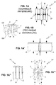
- the first approach ( patent application no. FR 2 962 614 published on January 13, 2012 on behalf of the applicant) is illustrated in the Figure 1A intended to explain the operation of the vibrating core 10 of the resonator, and to Figure 1B which shows a perspective view in longitudinal section of the resonator comprising the vibrating core 10 and a straight hollow cylinder CC of square directors surrounding the vibrating core 10 and intended to be assembled on a housing base EB.
- the vibrating core 10 of the resonator comprises a solid right cylinder R, a hollow right cylinder 2 of the same height surrounding the solid right cylinder, and a membrane 1 disposed in the median plane n and integral with the cylindrical surface of the solid cylinder and the inner cylindrical surface of the hollow cylinder.
- the solid cylinder R vibrates according to a longitudinal extension-compression resonance mode and has a vibration node N located in the median plane ⁇ , and the hollow cylinder 2 also vibrates in longitudinal extension-compression resonance mode, at the same frequency as the full cylinder, but in phase opposition with the vibration of the full cylinder.
- the identity of the resonance frequencies of the two cylinders comes from the identity of their heights, which is a necessary condition for the operation of the resonator (see page 9 line 37 to page 10 line 11 of the aforementioned patent).
- the anti-phase vibrations of the two cylinders correspond to a particular mechanical resonance mode of the vibrating core 10, that is to say to a spontaneous mode.
- the mass of the hollow cylinder 2 is much greater than the mass of the solid cylinder R, because the thickness of the wall of the hollow cylinder is of the order of magnitude of the diameter of the full cylinder (see page 12 line 2 to line 9). This geometrical condition implies that the mass of the hollow cylinder 2 is of the order of 10 times the mass of the solid cylinder R.
- the zone ZF can be almost decoupled from the vibration of the resonator, which allows, as shown in FIG. Figure 1B to hold the hollow cylinder 2 by means of P bridges integral with a hollow cylinder CC without altering the intrinsic quality coefficient of the resonator.
- the operation of this resonator known from the prior art is thus very satisfactory.
- the beams 2 ' In order to comply with the conditions recommended by the aforementioned patent, the beams 2 'should have the same height as the bar and a mass much greater than that of the bar, which would lead to the beams 2' to a very large dimension taken in the plan of the structure perpendicular to their height dimension, as illustrated in Figure 1A ' .
- the Figure 2A shows a front view of a contour vibration mode piezoelectric resonator 21 comprising a vibrating portion 26 and at least one support portion 25 forming a part with the vibrating portion by means of a bridge portion 31.
- the resonator 21 is characterized in that each support portion 25 consists of an elastic portion 30 interconnected with said vibrating portion 26, an attenuation portion 28 made of a piece with said elastic portion 30 and moving only in a minimal manner and a fixing portion 27 for attachment to a support member.
- the attenuation portion 28 is connected at both ends to the resilient portion 30 via connection portions 29, thereby forming a lumen in the support portion 25.
- the width of the bridge portion 31, the width of the elastic portion 30, the width of the attenuation portion 28, the distance between the elastic portion and the attenuation portion, and the length of the elastic portion are respectively W0 , W1, W2, W3 and L1, as shown in Figure 2B .
- FIGS. 2C and 2D show in dashed line the exaggeratedly enlarged deformations of the vibrating resonator on two contour modes respectively. It is specified that the resonator is provided to operate simultaneously on these two modes voluntarily coupled together, which is achieved by respecting certain dimensional ratios between the short side W and the long side L of the vibrating portion 26; this makes it possible to obtain an excellent frequency / temperature characteristic of the resonator.
- the disadvantage of this second approach concerns the difficulty of producing the resonator with sufficient accuracy to ensure proper operation. particularly at the level of the support portions 25 and more precisely with respect to the widths W1 and W2 of the elastic portion and the attenuation portion respectively, and the distance W3 between the elastic portion and the attenuation portion.
- This difficulty of realization all the greater as the dimensions of the resonator are small, is translated either by a brake to the miniaturization of the resonator, or by a relatively high manufacturing cost.
- the object of the invention is in particular to overcome the drawbacks of the earlier approaches by proposing a mechanical resonator whose operation is as satisfactory as that provided by the first and second approaches, but whose structure is better adapted to reducing congestion and the cost of the resonator.
- the mechanical resonator planar structure comprising a vibrating bar in an extension-compression resonance mode along its longitudinal central axis and having a vibration node in its median plane perpendicular to said longitudinal central axis, the vibration naturally inducing transverse extension-compression deformations, is characterized in that the structure comprises two parallelepipedal beams substantially identical to each other, each symmetrical with respect to said median plane and disposed respectively on either side of the bar, the axes longitudinals beams being parallel to said longitudinal central axis, the length of the beams being substantially equal to that of the bar and the slenderness of the beams taken in the plane of the structure being substantially equal to the result of the addition of six and a half and a number equal to twenty-eight percent of the slenderness of the bar taken in the plane of the structure, and two connecting elements respectively disposed of and else of the bar in the vicinity of said median plane and each connecting a face of the bar to a face of a
- the simultaneous vibrations of the bar in longitudinal extension-compression resonance mode and of the beams according to said first and second modes correspond to a particular mechanical resonance mode of the resonator structure according to the invention, for which the setting in vibration can be spontaneously obtained by exciting the bar in longitudinal extension-compression resonance mode.
- the first relationship length of the beams substantially equal to that of the bar
- the second relationship sinum thickness of the beams substantially equal to the result of the addition of six and a half and a number equal to twenty-eight percent of the slenderness of the bar
- the second relationship relates to the second mode and allows to work the beams in the vicinity of their bending resonance frequency.
- the two dimensional relationships condition the distribution of the transverse deformations of each of the beams coming from a part of said first longitudinal stretch-compression mode and secondly from said second bending mode, so that the effects of the overall transverse deformation of the beam compensates for the effects of the transverse deformations of the bar in said zone.
- the length and the slenderness of the beams allowing this compensation each have a single value.
- the resonator does not work if the second relationship is satisfied but not the first, because in this case there is no vibration of said first longitudinal extension-compression mode of the beams.
- said zone located on the face of each of the beams opposite to the integral face of the connecting element can be decoupled from the vibration of the bar and it is possible, by fixing the device on said zone, to obtain that the real quality coefficient of the bar is close to its large coefficient intrinsic quality.
- the resonator dimensioning is optimized for example by means of numerical simulations based on the finite element method.
- the resonator can be produced at very low cost by collective machining exclusively leading to a flat plate of uniform thickness material.
- the solid configuration of the resonator beams according to the invention allows the correct operation of the resonator to be less demanding as regards the precision of embodiment. .
- the resonator structure according to the invention is easier to produce, and therefore more favorable to reducing the cost and bulk of the resonator.
- the structure further comprises two fixing blocks disposed towards the outside of the structure and each connected to a beam by means of a connecting element disposed in the vicinity of said median plane, that is, that is to say in said zone, which allows that fixing of said blocks on a support does not alter the coefficient of quality of the resonator.
- the structure is made of quartz, the plane of the structure being parallel to the XY crystallographic plane and the longitudinal central axis of the bar being parallel to the crystallographic axis Y, and the structure is equipped with vibration setting acting by piezoelectric effect.
- the plane structure of mechanical resonator according to the third Embodiment is characterized in that the vibrating means comprise electrodes arranged on the faces of the bar and beams and extending parallel to the longitudinal central axis.
- planar mechanical resonator structure according to the fourth embodiment is characterized in that the structure is produced by chemical etching in sub-millimetric dimensions.
- planar mechanical resonator structure according to the fourth embodiment is characterized in that the structure is produced by reactive ion etching in sub-millimetric dimensions.
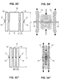
- FIG 3C shows a perspective view of a resonator 100 according to the invention.
- the structure of the resonator 100 is monolithic and made in a flat plate of material of uniform thickness b by means of machining exclusively opening; the structure is therefore well suited to integration techniques of micro systems.
- the material is advantageously chosen for its very low viscous damping; it may be for example an isotropic material such as silica, or a crystalline material such as quartz.
- the machining can be performed for example by reactive ion etching or by chemical etching.
- the resonator 100 comprises a parallelepipedal R bar whose longitudinal central axis ⁇ extends parallel to the plane of the plate and whose median plane n perpendicular to said central longitudinal axis ⁇ is perpendicular to the plane of the plate.
- the dimensions of the bar R taken in the plane of the plate are its length L and its width a; the slenderness of the bar R taken in the plane of the plate is therefore L / a. In the illustrated representation, said slenderness of the bar is substantially equal to 4.
- the resonator according to the invention does not impose a precise recommendation. It is simply necessary to ensure that the thickness b is not too low (which could induce parasitic vibration modes transverse to the plate) or too strong (Poisson effects transverse to the plate could hinder the proper functioning of the resonator ).
- the resonator according to the invention is well suited to a thickness b of the plate of the order of magnitude of the width c of the beams.
- the resonator 100 also comprises two connecting elements 11 disposed respectively on either side of the bar in the vicinity of said median plane and each connecting a machined face of the bar to a machined face of a beam.
- the resonator 100 also comprises two fixing blocks PF disposed towards the outside of the resonator and each connected to a beam 12 by means of a connecting element 13 disposed in the vicinity of the median plane ⁇ .
- the fixing blocks PF are intended to be assembled on an EB housing base (not shown).
- the figure 3A shows exaggeratedly enlarged deformations of the vibrating bar R according to an extension-compression resonance mode along its longitudinal central axis ⁇ and having a vibration node N in its median plane ⁇ , the vibration naturally inducing transverse extension-compression deformations due to the Poisson's ratio of the material and indicated in the figure by means of V-shaped arrows, said transverse deformations being maximum in the median plane ⁇ and zero at the ends of the bar.
- the bar R shown at figure 3A and its longitudinal extension-compression vibration naturally inducing transverse deformations are analogous to the full right R cylinder of the prior art shown in FIG. Figure 1A and its vibration.
- the beams 12 each vibrate simultaneously in two modes, the first mode being a longitudinal extension-compression mode in phase opposition with the vibration of the bar, the second mode being a bending mode (partial second) occurring parallel to the plane of the plate, the mechanical excitation of the beams being effected at the level of the connecting elements 11.
- the first relationship length of the beams substantially equal to that of the bar
- the second relation slenderness of the beams substantially equal to the result of the addition of six and a half and a number equal to twenty-eight percent of the slenderness of the bar
- the bending resonance frequency of the beams is about 10% higher than the frequency of the resonator.
- the two dimensional relationships condition the distribution of the transverse deformations of each of the beams coming from a part of said first longitudinal stretch-compression mode and secondly from said second bending mode, so that the effects of the overall transverse deformation of the beam compensates the effects of the transverse deformations of the bar in a zone Z situated on the face of the beam opposite to the integral face of the connecting element 11 and in the vicinity of the median plane ⁇ , as well as is explained in the following in relation to the figure 3B .
- the figure 3B shows the superposition of different states of the exaggeratedly enlarged deformation of a beam 12 during the half-period of the vibration of the resonator corresponding to the longitudinal compression of the bar.
- the beam deforms simultaneously in extension (said first mode) and in flexion (said second mode), and that its width dimension, initially c, undergoes an alternating variation during the vibration, said maximum variation being maximum at neighborhood of the median plane ⁇ and zero at the ends of the beam; said alternative variation results from the combination of two phenomena.
- the first phenomenon is the transverse deformation of the beam (Poisson effect) related to its longitudinal extension.
- the second phenomenon is the transverse deformation of the beam related to its bending and its mechanical excitation by the connecting element 11.
- the connecting elements 13 located in the zones Z can be completely decoupled from the vibration of the bar, and it is possible by fixing the vibrating core of the resonator at the level of said connecting elements, for example by means of the fixing blocks PF shown to the figure 3C to obtain that the real quality coefficient of the bar is close to its great intrinsic quality coefficient.
- the proper operation of the resonator according to the invention is less demanding on the accuracy of realization than the resonator according to the second approach illustrated in FIGS. Figures 2A and 2B .
- the support portions of the resonator according to the second approach comprise elements of relatively small dimensions (in particular the thicknesses W1 and W3 of the elastic portion 30 and the attenuation portion 28), which is not the case of the solid beams of the resonator according to the invention.
- the structure of the resonator according to the invention is better suited to reducing the size and the cost of the resonator.
- the expression "parallelepiped beam”, as used here, is to be considered in the broad sense, the important thing being that the operation of the resonator is similar to that just described.
- the face contour of the beams, rectangular in the figures illustrating the invention may have chamfers or roundings replacing sharp corners. This is not a disadvantage for the operation of the resonator according to the invention if care is taken to take these forms into account in the numerical simulations used to optimize the operation of the resonator.
- the Figure 3C ' shows a front view of the vibrating core of another resonator according to the invention, for which the slenderness L / a of the bar R is substantially equal to 2.
- the length of the beams 12 is substantially equal to the length L of the bar and their width c is such that the slenderness L / c of the beams is substantially the result of the addition of 6.5 and a number equal to 28% of the slenderness L / a of the bar; in this case, the slenderness of the beams is substantially:
- FIG. 3A which shows exaggeratedly enlarged deformations of this vibrating core, we see that the beams 12 each vibrate simultaneously in said first and second modes, and the results of the finite element numerical simulations indicate that the connecting elements 13 undergo substantially no displacement at during the vibration.
- the Figure 3C " shows a front view of the vibrating core of another resonator according to the invention, for which the slenderness L / a of the bar R is substantially equal to 10.
- the length of the beams 12 is substantially equal to the length L of the bar and their width c is such that the slenderness L / c of the beams is substantially the result of the addition of 6.5 and a number equal to 28% of the slenderness L / a of the bar; in this case, the slenderness of the beams is substantially:
- the resonator according to the invention is suitable for any slenderness of the bar.
- the extension-compression resonance frequency of the bar is substantially proportional to the magnitude 1 / L
- the bending resonance frequency of the beams is substantially proportional to the magnitude c / L 2 .
- the resonator according to the invention is well suited to miniaturization.
- quartz resonator of overall dimensions 500 ⁇ m ⁇ 500 ⁇ m ⁇ 50 ⁇ m whose frequency is of the order of 5 MHz and whose quality coefficient is greater than 10 6 .
- the Figure 4A shows the resonator 100 of the figure 3C whose bar R is equipped with electrodes 20 and 21 acting by piezoelectric effect.
- the electrodes 20 and 21 are disposed on each of the two faces of the flush bar R the large faces of the plate, and are in the form of ribbons extending parallel to the longitudinal axis ⁇ which is also the mechanical crystallographic axis Y of quartz.
- the Figure 4A shows the electrodes 20 and 21 on one of said faces of the bar; the electrodes 20 and 21 on the other side, indicated by means of a dotted reference line, are respectively arranged facing each other.
- the electrodes 20 and 21 are able to create in the bar an electric field whose component E X perpendicular to the longitudinal axis ⁇ and parallel to the large faces of the plate is coupled by piezoelectric effect to the mechanical stress of extension or compression T YY intervenes predominantly in the extension-compression vibration of the bar R.
- the electrodes 20 and 21 are effective means for vibrating the bar R.
- the beams 12 of the resonator 100 are also equipped with electrodes acting by piezoelectric effect and also referenced 20 and 21 to translate the identity of the polarities with the electrodes of the R bar.
- the arrangement of the electrodes of the beams 12 makes it possible to create in the beams an electric field whose component E X is opposite to that of the bar.
- the electrodes 20 and 21 are able to excite in the beams a longitudinal extension-compression vibration in phase opposition with the longitudinal extension-compression vibration of the bar.
- the electrodes 20 and 21 equipping the beams are not necessary for the operation of the resonator according to the invention, since the vibration of the bar is sufficient, mechanically, to vibrate the beams in phase opposition as explained previously. Nevertheless, the electrodes 20 and 21 equipping the beams are interesting because they make it possible to improve the piezoelectric coupling of the resonator.
- the electrodes 20 and 21 are connected to electrical connection pads 40 and 41, respectively, arranged on the fixing blocks PF, by means of connection strips 30 and 31 running on the connecting elements 11 and 13, the beams 12 and PF fixing blocks.
- the Figure 4B shows the resonator 100 equipped with electrodes 20 'and 21' more complete than the electrodes 20 and 21 of the Figure 4A .
- the electrodes 20 'and 21' comprise, in addition to strips disposed on the faces of the bar and beams flush with the two large faces of the plate, other strips arranged on the machined faces of the bar and the beams and made for example by evaporation of metal in oblique directions with respect to the main axes of the resonator, each of said other ribbons being in electrical contact with the ribbon of a large face flush with the common edge.
- the E X component of the electric field may be more intense, and the efficiency of the electrodes 20 'and 21' greater than that of the electrodes 20 and 21, however, with additional manufacturing costs.
- connection strips 30 and 31 and the connection pads 40 and 41 are provided by said other ribbons, it is no longer necessary to arrange the connection strips 30 and 31 and the connection pads 40 and 41 on the two large faces of the resonator .
Description
Le domaine technique de l'invention est celui des résonateurs mécaniques permettant de réaliser des instruments de mesure du temps ou de la fréquence. Plus particulièrement, l'invention concerne un résonateur mécanique à grand coefficient de qualité destiné par exemple à des horloges de haute stabilité appelées « Oscillateurs Ultra Stables » (OUS).The technical field of the invention is that of mechanical resonators for producing instruments for measuring time or frequency. More particularly, the invention relates to a mechanical resonator with high quality coefficient for example for high stability clocks called "Ultra Stable Oscillators" (OUS).
Le problème technique à résoudre est de réduire l'encombrement et le coût de fabrication du résonateur.The technical problem to be solved is to reduce the size and the cost of manufacturing the resonator.
Avant de présenter l'état de l'art, il est utile de préciser ci-après la notion de coefficient de qualité d'un résonateur mécanique.Before presenting the state of the art, it is useful to specify below the notion of quality coefficient of a mechanical resonator.
Dans les OUS, le résonateur mécanique est associé à une boucle électronique oscillatrice qui permet d'entretenir la vibration du résonateur à sa fréquence de résonance mécanique. Ainsi, la stabilité de la fréquence du signal électrique alternatif présent dans la boucle électronique bénéficie de la stabilité de la fréquence de la résonance mécanique du résonateur, généralement beaucoup plus grande que celle d'une boucle oscillatrice purement électronique.In the OUS, the mechanical resonator is associated with an oscillating electronic loop which makes it possible to maintain the vibration of the resonator at its mechanical resonance frequency. Thus, the stability of the frequency of the alternating electric signal present in the electronic loop benefits from the stability of the frequency of the mechanical resonance of the resonator, generally much greater than that of a purely electronic oscillating loop.
La stabilité de la fréquence de résonance du résonateur mécanique est d'autant plus grande que le coefficient de qualité de la vibration de résonance est élevé, autrement dit que l'énergie de vibration contenue dans le résonateur est grande vis-à-vis de l'énergie perdue par période de la vibration. Il existe deux types de pertes d'énergie, d'une part les pertes intrinsèques dues par exemple à l'amortissement visqueux du matériau constituant le résonateur, d'autre part les pertes extrinsèques dues par exemple à un amortissement gazeux ou à une fixation inadaptée du résonateur. C'est pour cela que les meilleurs résonateurs sont réalisés dans des matériaux de très faible amortissement visqueux tels le quartz, qu'ils sont conditionnés sous vide dans un boîtier, et qu'ils sont fixés dans ce boîtier à l'emplacement de ce qu'il est convenu d'appeler idéalement un noeud de vibration.The stability of the resonance frequency of the mechanical resonator is greater the higher the quality coefficient of the resonance vibration, ie the vibration energy contained in the resonator is large compared to the resonator. lost energy per period of vibration. There are two types of energy losses, on the one hand the intrinsic losses due for example to the viscous damping of the material constituting the resonator, on the other hand the extrinsic losses due for example to a gaseous damping or to a fixation. unsuitable resonator. That is why the best resonators are made of materials with very low viscous damping such as quartz, they are vacuum packed in a housing, and they are fixed in this housing at the location of what it is agreed to ideally call a vibration node.
Il existe une formulation pratique pour exprimer la contribution des différentes sources de pertes d'énergie, ainsi qu'il est expliqué dans ce qui suit.There is a practical formulation to express the contribution of the different sources of energy losses, as explained in the following.
L'expression du coefficient de qualité réel du résonateur s'écrit : ![]()
![]()
Où E est l'énergie contenue dans le résonateur et ΔE l'énergie perdue par période de la vibration. Pour les exemples précédemment cités, ΔE peut s'écrire : ![]()
![]()
On peut donc écrire : ![]()
![]()
Soit : 
Ainsi, on peut associer à chaque source de pertes d'énergie un facteur de qualité qui lui est propre, et écrire : ![]()
![]()
Pour que le coefficient de qualité réel du résonateur soit proche de son coefficient de qualité intrinsèque, il faut donc que les coefficients de qualité associés aux différentes sources de pertes extrinsèques soient très supérieurs au coefficient de qualité intrinsèque. A titre d'exemple, si Q intrinsèque est de l'ordre de 106, il est souhaitable que Q fixation et Q gaz soient de l'ordre d'au moins 107.So that the real coefficient of quality of the resonator is close to its intrinsic quality coefficient, it The quality coefficients associated with the different sources of extrinsic losses must therefore be much higher than the intrinsic quality coefficient. By way of example, if intrinsic Q is of the order of 10 6 , it is desirable that Q fixation and Q gas be of the order of at least 10 7 .
L'invention concerne les pertes dues à la fixation du résonateur, et vise à obtenir que Q fixation soit très supérieur à Q intrinsèque, tout en bénéficiant d'un encombrement et d'un coût de fabrication très faible.The invention relates to losses due to the fixing of the resonator, and aims to obtain that Q fixation is much higher than intrinsic Q, while enjoying a footprint and a very low manufacturing cost.
L'état de l'art le plus proche regroupe les deux approches suivantes. Pour la première approche, de même que pour l'invention, la vibration du résonateur est un mode d'extension-compression. Pour la seconde approche, la vibration du résonateur est un mode de contour, ce qui signifie que la structure de la partie vibrante du résonateur est plane et que les vibrations s'effectuent principalement parallèlement à son plan ; il peut s'agir par exemple de vibrations d'extension-compression, de cisaillement ou de flexion.The closest state of the art brings together the following two approaches. For the first approach, as for the invention, the vibration of the resonator is an extension-compression mode. For the second approach, the vibration of the resonator is a mode of contour, which means that the structure of the vibrating part of the resonator is plane and that the vibrations take place mainly parallel to its plane; it may be, for example, extension-compression, shear or bending vibrations.
La première approche (demande de brevet n°
En se référant à la
Le cylindre plein R vibre selon un mode de résonance d'extension-compression longitudinale et présente un nceud N de vibration situé dans le plan médian π, et le cylindre creux 2 vibre également en mode de résonance d'éxtension-compression longitudinale, à la même fréquence que le cylindre plein, mais en opposition de phase avec la vibration du cylindre plein. L'identité des fréquences de résonance des deux cylindres provient de l'identité de leurs hauteurs, qui est une condition nécessaire au fonctionnement du résonateur (cf page 9 ligne 37 à page 10 ligne 11 du brevet précité). Les vibrations en opposition de phase des deux cylindres correspondent à un mode de résonance mécanique particulier du coeur vibrant 10, c'est-à-dire à un mode spontané.The solid cylinder R vibrates according to a longitudinal extension-compression resonance mode and has a vibration node N located in the median plane π, and the
La masse du cylindre creux 2 est très supérieure à la masse du cylindre plein R, car l'épaisseur de la paroi du cylindre creux est de l'ordre de grandeur du diamètre du cylindre plein (cf page 12 ligne 2 à ligne 9). Cette condition géométrique implique en effet que la masse du cylindre creux 2 est de l'ordre de 10 fois la masse du cylindre plein R.The mass of the
Il en découle que l'amplitude de vibration du cylindre creux est très inférieure à celle du cylindre plein, afin que s'équilibrent naturellement les quantités de mouvement mises en jeu dans ledit mode de résonance particulier (cf page 10 ligne 14 à ligne 22). Cela permet que les effets des déformations radiales (effets de Poisson) des deux cylindres se compensent dans une zone ZF située sur la surface extérieure du cylindre creux au voisinage du plan médian π.It follows that the amplitude of vibration of the hollow cylinder is much lower than that of the solid cylinder, so that the amounts of movement involved in said particular resonance mode naturally balance (see
Ainsi, la zone ZF peut être quasiment découplée de la vibration du résonateur, ce qui permet, comme montré à la
L'enseignement de la première approche est par ailleurs complété dans l'article intitulé "A Micro-Resonator for Fundamental Physics Experiments an its Possible Interest for Time and Frequency Applications" de Olivier Le Traon (European Frequency and Time Forum, 2011) qui indique que l'extension-compression du cylindre creux s'accompagne d'une courbure de sa paroi (
Les inconvénients de cette première approche résident en premier lieu dans l'encombrement du résonateur dû à sa structure tridimensionnelle mal adaptée aux techniques d'intégration de micro systèmes dont les structures sont généralement planes ; en second lieu, le bon fonctionnement du résonateur est exigeant sur la symétrie du résonateur par rapport au plan médian π, particulièrement sur la position de la membrane 1 obtenue en contrôlant la profondeur des usinages effectués parallèlement à l'axe longitudinal Δ du résonateur, ce qui grève le coût de fabrication. The disadvantages of this first approach reside primarily in the size of the resonator due to its three-dimensional structure poorly adapted to the integration techniques of micro systems whose structures are generally flat; second, the good functioning of the resonator is demanding on the symmetry of the resonator with respect to the median plane π , particularly on the position of the
Il pourrait paraître intéressant de s'inspirer de cette première approche en tentant de faire fonctionner une structure plane de coeur vibrant sur un mode similaire à celui décrit dans la première approche, ainsi qu'illustré à la
Afin de respecter les conditions préconisées par le brevet précité, les poutres 2' devraient avoir la même hauteur que celle du barreau et une masse très supérieure à celle du barreau, ce qui conduirait pour les poutres 2' à une très grande dimension prise dans le plan de la structure perpendiculairement à leur dimension de hauteur, ainsi qu'il est illustré à la
Ainsi, cette nouvelle approche, bien que bénéficiant de l'avantage d'une structure plane, présenterait comme la première approche l'inconvénient d'un encombrement important.Thus, this new approach, although enjoying the advantage of a flat structure, would present as the first approach the disadvantage of a large footprint.
Il pourrait également paraître intéressant de s'inspirer seulement de la
La seconde approche de l'état de l'art le plus proche est montrée dans le
La
La partie d'atténuation 28 est connectée par ses deux extrémités à la partie élastique 30 par l'intermédiaire de parties de connexion 29, formant ainsi une lumière dans la portion support 25.The
La largeur de la partie en pont 31, la largeur de la partie élastique 30, la largeur de la partie d'atténuation 28, la distance entre la partie élastique et la partie d'atténuation, et la longueur de la partie élastique sont respectivement W0, W1, W2, W3 et L1, comme le montre la
Ces dimensions jouent un rôle important dans le fonctionnement de ce résonateur, en particulier dans le découplage des vibrations de la portion vibrante 26 vis-à-vis de la partie de fixation 27. Lorsque que ces dimensions satisfont un certain nombre de relations précisées dans le brevet précité, alors le découplage peut être excellent ainsi qu'illustré aux
Les
Pour obtenir le découplage des vibrations de la portion vibrante 26 vis-à-vis de la partie de fixation 27, il est donc nécessaire que chacun des deux modes de contour illustrés aux
L'enseignement de la seconde approche est par ailleurs complété dans l'article intitulé "
Bien que l'article soit très peu explicite sur le fonctionnement de ce résonateur (quelques lignes à la fin de la conclusion), l'homme du métier peut reconnaître le dispositif de la seconde approche illustré à la
Les structures planes des résonateurs de la seconde approche et leurs usinages exclusivement débouchants sont bien adaptés aux techniques d'intégration de micro systèmes.The flat structures of the resonators of the second approach and their exclusively open machining are well adapted to the techniques of integration of micro systems.
Par contre, l'inconvénient de cette seconde approche concerne la difficulté de réaliser le résonateur avec une précision suffisante pour assurer un bon fonctionnement, notamment au niveau des portions supports 25 et plus précisément en ce qui concerne les largeurs W1 et W2 de la partie élastique et de la partie d'atténuation respectivement, ainsi que la distance W3 entre la partie élastique et la partie d'atténuation. Cette difficulté de réalisation, d'autant plus grande que les dimensions du résonateur sont petites, se traduit soit par un frein à la miniaturisation du résonateur, soit par un coût de fabrication relativement élevé.On the other hand, the disadvantage of this second approach concerns the difficulty of producing the resonator with sufficient accuracy to ensure proper operation. particularly at the level of the support portions 25 and more precisely with respect to the widths W1 and W2 of the elastic portion and the attenuation portion respectively, and the distance W3 between the elastic portion and the attenuation portion. This difficulty of realization, all the greater as the dimensions of the resonator are small, is translated either by a brake to the miniaturization of the resonator, or by a relatively high manufacturing cost.
L'invention a notamment pour but de surmonter les inconvénients des approches antérieures en proposant un résonateur mécanique dont le fonctionnement est aussi satisfaisant que celui procuré par les première et seconde approches, mais dont la structure est mieux adaptée à la réduction de l'encombrement et du coût du résonateur. The object of the invention is in particular to overcome the drawbacks of the earlier approaches by proposing a mechanical resonator whose operation is as satisfactory as that provided by the first and second approaches, but whose structure is better adapted to reducing congestion and the cost of the resonator.
Pour bien comprendre les éléments caractérisant l'invention, il est utile de rappeler que l'élancement d'une poutre parallélépipédique, pris dans un plan porté par sa dimension de longueur L et l'une de ses deux dimensions de section c, est défini par le rapport L/c.To understand the elements characterizing the invention, it is useful to remember that the slenderness of a parallelepiped beam, taken in a plane carried by its length dimension L and one of its two dimensions of section c, is defined by the ratio L / c.
Afin de surmonter les inconvénients des approches antérieures, la structure plane de résonateur mécanique comportant un barreau vibrant selon un mode de résonance d'extension-compression suivant son axe central longitudinal et présentant un noeud de vibration dans son plan médian perpendiculaire audit axe central longitudinal, la vibration induisant naturellement des déformations transverses d'extension-compression, est caractérisée en ce que la structure comporte deux poutres parallélépipédiques sensiblement identiques entre elles, symétriques chacune par rapport audit plan médian et disposées respectivement de part et d'autre du barreau, les axes longitudinaux des poutres étant parallèles audit axe central longitudinal, la longueur des poutres étant sensiblement égale à celle du barreau et l'élancement des poutres pris dans le plan de la structure étant sensiblement égal au résultat de l'addition de six et demi et d'un nombre valant vingt-huit pour-cent de l'élancement du barreau pris dans le plan de la structure, et deux éléments de liaison disposés respectivement de part et d'autre du barreau au voisinage dudit plan médian et reliant chacun une face du barreau à une face d'une poutre, ce grâce à quoi les poutres, excitées au niveau des éléments de liaison par lesdites déformations transverses d'extension-compression du barreau, vibrent chacune simultanément selon deux modes, le premier mode étant un mode d'extension-compression longitudinale en opposition de phase avec la vibration du barreau, le second mode étant un mode de flexion s'effectuant parallèlement au plan de la structure, et les effets des déformations transverses du barreau et de chacune des poutres se compensent dans une zone située sur la face de la poutre opposée à la face solidaire de l'élément de liaison et au voisinage dudit plan médian.In order to overcome the drawbacks of prior approaches, the mechanical resonator planar structure comprising a vibrating bar in an extension-compression resonance mode along its longitudinal central axis and having a vibration node in its median plane perpendicular to said longitudinal central axis, the vibration naturally inducing transverse extension-compression deformations, is characterized in that the structure comprises two parallelepipedal beams substantially identical to each other, each symmetrical with respect to said median plane and disposed respectively on either side of the bar, the axes longitudinals beams being parallel to said longitudinal central axis, the length of the beams being substantially equal to that of the bar and the slenderness of the beams taken in the plane of the structure being substantially equal to the result of the addition of six and a half and a number equal to twenty-eight percent of the slenderness of the bar taken in the plane of the structure, and two connecting elements respectively disposed of and else of the bar in the vicinity of said median plane and each connecting a face of the bar to a face of a beam, thanks to which the beams, excited at the level of the connecting elements by said transverse extension-compression deformations of the bar each vibrate simultaneously in two modes, the first mode being a longitudinal extension-compression mode in phase opposition with the vibration of the bar, the second mode being a bending mode occurring parallel to the plane of the structure, and the The effects of the transverse deformations of the bar and of each of the beams are compensated in an area situated on the face of the beam opposite the integral face of the connecting element and in the vicinity of the beam. t median plane.
Les vibrations simultanées du barreau en mode de résonance d'extension-compression longitudinale et des poutres selon lesdits premier et second modes correspondent à un mode de résonance mécanique particulier de la structure de résonateur selon l'invention, pour lequel la mise en vibration peut être spontanément obtenue en excitant le barreau en mode de résonance d'extension-compression longitudinale.The simultaneous vibrations of the bar in longitudinal extension-compression resonance mode and of the beams according to said first and second modes correspond to a particular mechanical resonance mode of the resonator structure according to the invention, for which the setting in vibration can be spontaneously obtained by exciting the bar in longitudinal extension-compression resonance mode.
Les deux relations dimensionnelles indiquées ci-dessus entre les poutres et le barreau sont nécessaires au bon fonctionnement du résonateur selon l'invention, car en premier lieu elles permettent la coexistence desdits premier et second modes de vibration des poutres : la première relation (longueur des poutres sensiblement égale à celle du barreau) concerne le premier mode et permet de faire travailler les poutres sensiblement à leur fréquence de résonance en extension-compression longitudinale ; en addition à la première relation, la seconde relation (élancement des poutres sensiblement égal au résultat de l'addition de six et demi et d'un nombre valant vingt-huit pour-cent de l'élancement du barreau) concerne le second mode et permet de faire travailler les poutres au voisinage de leur fréquence de résonance en flexion.The two dimensional relationships indicated above between the beams and the bar are necessary for the proper functioning of the resonator according to the invention, because in the first place they allow the coexistence of said first and second vibration modes of the beams: the first relationship (length of the beams substantially equal to that of the bar) relates to the first mode and makes it possible to make the beams work substantially at their resonance frequency in longitudinal extension-compression; in addition to the first relationship, the second relationship (slenderness of the beams substantially equal to the result of the addition of six and a half and a number equal to twenty-eight percent of the slenderness of the bar) relates to the second mode and allows to work the beams in the vicinity of their bending resonance frequency.
En second lieu, les deux relations dimensionnelles conditionnent la répartition des déformations transverses de chacune des poutres provenant d'une part dudit premier mode d'extension-compression longitudinale et d'autre part dudit second mode de flexion, de telle sorte que les effets de la déformation transverse globale de la poutre compensent les effets des déformations transverses du barreau dans ladite zone.Secondly, the two dimensional relationships condition the distribution of the transverse deformations of each of the beams coming from a part of said first longitudinal stretch-compression mode and secondly from said second bending mode, so that the effects of the overall transverse deformation of the beam compensates for the effects of the transverse deformations of the bar in said zone.
Ainsi, pour un barreau de longueur et d'élancement donnés, la longueur et l'élancement des poutres permettant cette compensation ont chacun une valeur unique.Thus, for a bar of given length and slenderness, the length and the slenderness of the beams allowing this compensation each have a single value.
A titre d'illustration, si la première relation est satisfaite mais que la seconde ne l'est pas, alors les effets des déformations transverses provenant dudit second mode de flexion ne sont pas ajustés pour obtenir la compensation des effets des déformations transverses du barreau et de chacune des poutres dans ladite zone, et le résonateur ne fonctionne pas ; c'est le cas notamment du coeur vibrant inspiré de la première approche et montré aux
De même, le résonateur ne fonctionne pas si la seconde relation est satisfaite mais pas la première, car dans ce cas il n'y a pas de mise en vibration dudit premier mode d'extension-compression longitudinale des poutres.Similarly, the resonator does not work if the second relationship is satisfied but not the first, because in this case there is no vibration of said first longitudinal extension-compression mode of the beams.
Lorsque les deux relations dimensionnelles sont satisfaites, ladite zone située sur la face de chacune des poutres opposée à la face solidaire de l'élément de liaison peut être découplée de la vibration du barreau et il est possible, en fixant le dispositif sur ladite zone, d'obtenir que le coefficient de qualité réel du barreau soit voisin de son grand coefficient de qualité intrinsèque. Afin d'obtenir le découplage maximal, le dimensionnement du résonateur est optimisé par exemple au moyen de simulations numériques basées sur la méthode des éléments finis.When the two dimensional relationships are satisfied, said zone located on the face of each of the beams opposite to the integral face of the connecting element can be decoupled from the vibration of the bar and it is possible, by fixing the device on said zone, to obtain that the real quality coefficient of the bar is close to its large coefficient intrinsic quality. In order to obtain the maximum decoupling, the resonator dimensioning is optimized for example by means of numerical simulations based on the finite element method.
De plus, le résonateur peut être réalisé à très faible coût par usinage collectif exclusivement débouchant d'une plaque plane de matériau d'épaisseur uniforme.In addition, the resonator can be produced at very low cost by collective machining exclusively leading to a flat plate of uniform thickness material.
Par rapport à la configuration relativement complexe des portions supports (25) de la seconde approche montrée à la
Selon un deuxième mode particulier de réalisation, la structure comporte en outre deux pavés de fixation disposés vers l'extérieur de la structure et reliés chacun à une poutre au moyen d'un élément de liaison disposé au voisinage dudit plan médian, c'est-à-dire dans ladite zone, ce qui permet que la fixation desdits pavés sur un support n'altère pas le coefficient de qualité du résonateur.According to a second particular embodiment, the structure further comprises two fixing blocks disposed towards the outside of the structure and each connected to a beam by means of a connecting element disposed in the vicinity of said median plane, that is, that is to say in said zone, which allows that fixing of said blocks on a support does not alter the coefficient of quality of the resonator.
Selon un troisième mode particulier de réalisation, la structure est en quartz, le plan de la structure étant parallèle au plan cristallographique XY et l'axe central longitudinal du barreau étant parallèle à l'axe cristallographique Y, et la structure est équipée de moyens de mise en vibration agissant par effet piézoélectrique.According to a third particular embodiment, the structure is made of quartz, the plane of the structure being parallel to the XY crystallographic plane and the longitudinal central axis of the bar being parallel to the crystallographic axis Y, and the structure is equipped with vibration setting acting by piezoelectric effect.
Selon un quatrième mode particulier de réalisation, la structure plane de résonateur mécanique selon le troisième mode de réalisation est caractérisée en ce que les moyens de mise en vibration comportent des électrodes disposées sur des faces du barreau et des poutres et s'étendant parallèlement à l'axe central longitudinal.According to a fourth particular embodiment, the plane structure of mechanical resonator according to the third Embodiment is characterized in that the vibrating means comprise electrodes arranged on the faces of the bar and beams and extending parallel to the longitudinal central axis.
Selon un cinquième mode particulier de réalisation, la structure plane de résonateur mécanique selon le quatrième mode de réalisation est caractérisée en ce que la structure est réalisée par gravure chimique dans des dimensions sub-millimétriques.According to a fifth particular embodiment, the planar mechanical resonator structure according to the fourth embodiment is characterized in that the structure is produced by chemical etching in sub-millimetric dimensions.
Selon un sixième mode particulier de réalisation, la structure plane de résonateur mécanique selon le quatrième mode de réalisation est caractérisée en ce que la structure est réalisée par gravure ionique réactive dans des dimensions sub-millimétriques.According to a sixth particular embodiment, the planar mechanical resonator structure according to the fourth embodiment is characterized in that the structure is produced by reactive ion etching in sub-millimetric dimensions.
Les caractéristiques et avantages de l'invention apparaîtront plus clairement à la lecture de la description détaillée et des figures qui s'y rapportent dans lesquelles :
- la
figure 1A est destinée à expliquer le fonctionnement du coeur vibrant d'un résonateur selon la technique antérieure et déjà commenté ; - la
figure 1B est une vue en perspective et en coupe longitudinale dudit résonateur selon la technique antérieure et déjà commentée ; - la
figure 1A' est une vue en perspective d'un coeur vibrant dont le fonctionnement est inspiré de celui du coeur vibrant de lafigure 1A et déjà commentée ; - la
figure 1A" est une vue en perspective d'un autre coeur vibrant dont le fonctionnement est inspiré de celui du coeur vibrant de lafigure 1A et déjà commentée ; - la
figure 1A"' est destinée à expliquer le fonctionnement du coeur vibrant de lafigure 1A" et déjà commentée ; - les
figures 2A et 2B sont des vues de face d'un autre résonateur selon la technique antérieure et déjà commentées ; - les
figures 2C et 2D montrent, sur seulement un quart du résonateur de lafigure 2A , des déformations du résonateur vibrant sur deux modes de contour respectivement et déjà commentées ; - la
figure 2A' est une vue en perspective d'un autre résonateur selon la technique antérieure et déjà commentée ; - les
figures 3A et 3B sont destinées à expliquer le fonctionnement du coeur vibrant d'un résonateur selon l'invention ; - la
figure 3C est une vue en perspective d'un résonateur selon l'invention ; - les
figures 3A' et 3C' montrent des vues de face du coeur vibrant d'un autre résonateur selon l'invention, pour lequel l'élancement du barreau est plus petit que celui illustré auxfigures 3A et 3C ; - les
figures 3A" et 3C" montrent des vues de face du coeur vibrant d'un autre résonateur selon l'invention, pour lequel l'élancement du barreau est plus grand que celui illustré auxfigures 3A et 3C ; et - les
figures 4A et 4B montrent des électrodes permettant l'excitation par effet piézoélectrique de la vibration du résonateur de lafigure 3C dans le cas où celui-ci est en quartz.
- the
Figure 1A is intended to explain the operation of the vibrating core of a resonator according to the prior art and already commented; - the
Figure 1B is a perspective view in longitudinal section of said resonator according to the prior art and already commented; - the
Figure 1A ' is a perspective view of a vibrant heart whose functioning is inspired by that of the vibrant heart of theFigure 1A and already commented; - the
Figure 1A " is a perspective view of another vibrating heart whose functioning is inspired by that of the vibrant heart of theFigure 1A and already commented; - the
figure 1A "' is intended to explain the functioning of the vibrant heart of theFigure 1A " and already commented; - the
Figures 2A and 2B are front views of another resonator according to the prior art and already commented; - the
Figures 2C and 2D show, on only a quarter of the resonator of theFigure 2A , deformations of the vibrating resonator on two contour modes respectively and already commented; - the
FIG. 2A ' is a perspective view of another resonator according to the prior art and already commented; - the
Figures 3A and 3B are intended to explain the operation of the vibrating core of a resonator according to the invention; - the
figure 3C is a perspective view of a resonator according to the invention; - the
FIGS. 3A 'and 3C' show front views of the vibrating core of another resonator according to the invention, for which the slenderness of the bar is smaller than that illustrated in FIGS.Figures 3A and 3C ; - the
Figures 3A "and 3C" show front views of the vibrating core of another resonator according to the invention, for which the slenderness of the bar is greater than that illustrated in FIGS.Figures 3A and 3C ; and - the
Figures 4A and 4B show electrodes allowing the piezoelectric excitation of the resonator vibration of thefigure 3C in the case where it is quartz.
On se réfère d'abord à la
Le résonateur 100 comporte un barreau R parallélépipédique dont l'axe central longitudinal Δ s'étend parallèlement au plan de la plaque et dont le plan médian n perpendiculaire audit axe central longitudinal Δ est donc perpendiculaire au plan de la plaque.The
Les dimensions du barreau R prises dans le plan de la plaque sont sa longueur L et sa largeur a ; l'élancement du barreau R pris dans le plan de la plaque vaut donc L/a. Sur la représentation illustrée, ledit élancement du barreau est sensiblement égal à 4.The dimensions of the bar R taken in the plane of the plate are its length L and its width a; the slenderness of the bar R taken in the plane of the plate is therefore L / a. In the illustrated representation, said slenderness of the bar is substantially equal to 4.
Le résonateur 100 comporte également deux poutres 12 parallélépipédiques sensiblement identiques entre elles, symétriques chacune par rapport au plan médian n et disposées respectivement de part et d'autre du barreau, les axes longitudinaux des poutres étant parallèles à l'axe central longitudinal Δ, la longueur des poutres étant sensiblement égale à la longueur L du barreau et leur largeur c étant telle que l'élancement L/c des poutres pris dans le plan de la plaque vaut sensiblement le résultat de l'addition de 6,5 et d'un nombre valant 28% de l'élancement L/a du barreau ; en l'occurrence, l'élancement des poutres vaut sensiblement : ![]()
![]()
Concernant la dimension d'épaisseur b de la plaque, le résonateur selon l'invention n'impose pas de recommandation précise. Il faut simplement veiller à ce que l'épaisseur b ne soit pas trop faible (ce qui pourrait induire des modes de vibrations parasites transverses à la plaque) ou trop forte (des effets de Poisson transverses à la plaque pourraient contrarier le bon fonctionnement du résonateur). Dans la pratique, le résonateur selon l'invention s'accommode bien d'une épaisseur b de la plaque de l'ordre de grandeur de la largeur c des poutres.Concerning the thickness dimension b of the plate, the resonator according to the invention does not impose a precise recommendation. It is simply necessary to ensure that the thickness b is not too low (which could induce parasitic vibration modes transverse to the plate) or too strong (Poisson effects transverse to the plate could hinder the proper functioning of the resonator ). In practice, the resonator according to the invention is well suited to a thickness b of the plate of the order of magnitude of the width c of the beams.
Le résonateur 100 comporte également deux éléments de liaison 11 disposés respectivement de part et d'autre du barreau au voisinage dudit plan médian et reliant chacun une face usinée du barreau à une face usinée d'une poutre.The
Le résonateur 100 comporte également deux pavés de fixation PF disposés vers l'extérieur du résonateur et reliés chacun à une poutre 12 au moyen d'un élément de liaison 13 disposé au voisinage du plan médian π. Les pavés de fixation PF sont destinés à être assemblés sur une embase de boîtier EB (non représentée).The
Le fonctionnement du résonateur selon l'invention est maintenant expliqué en relation avec les
Il est important de souligner que, pour ces simulations numériques, le coeur vibrant du résonateur est dissocié des pavés de fixation et qu'il n'est pas fixé, c'est-à-dire qu'il est totalement libre de se déplacer (on dit qu'il est "tenu par les anges").It is important to underline that, for these numerical simulations, the vibrating core of the resonator is dissociated from the fixing blocks and that it is not fixed, that is to say that it is totally free to move ( it is said that he is "held by the angels").
La
Toujours en se référant à la
Il est important de souligner que les vibrations simultanées du barreau en mode de résonance d'extension-compression longitudinale et des poutres selon lesdits premier et second modes correspondent à un mode de résonance mécanique particulier du résonateur selon l'invention, pour lequel la mise en vibration peut être spontanément obtenue en excitant le barreau en mode de résonance d'extension-compression longitudinale, par exemple en équipant le barreau de moyens de mise en vibration ainsi qu'il sera expliqué plus loin.It is important to underline that the simultaneous vibrations of the bar in longitudinal extension-compression resonance mode and the beams according to said first and second modes correspond to a particular mechanical resonance mode of the resonator according to the invention, for which the implementation This vibration can be spontaneously obtained by exciting the bar in longitudinal extension-compression resonance mode, for example by equipping the bar with vibrating means as will be explained later.
Les deux relations dimensionnelles expliquées précédemment entre les poutres et le barreau permettent en premier lieu la coexistence desdits premier et second modes : la première relation (longueur des poutres sensiblement égale à celle du barreau) concerne le premier mode et permet de faire travailler les poutres sensiblement à leur fréquence de résonance en extension-compression longitudinale ; en addition à la première relation, la seconde relation (élancement des poutres sensiblement égal au résultat de l'addition de six et demi et d'un nombre valant vingt-huit pour-cent de l'élancement du barreau) concerne le second mode et permet de faire travailler les poutres au voisinage de leur fréquence de résonance en flexion ; en l'occurrence, dans le cas du résonateur montré à la
En second lieu, les deux relations dimensionnelles conditionnent la répartition des déformations transverses de chacune des poutres provenant d'une part dudit premier mode d'extension-compression longitudinale et d'autre part dudit second mode de flexion, de telle sorte que les effets de la déformation transverse globale de la poutre compensent les effets des déformations transverses du barreau dans une zone Z située sur la face de la poutre opposée à la face solidaire de l'élément de liaison 11 et au voisinage du plan médian π, ainsi qu'il est expliqué dans ce qui suit en relation avec la
La
On voit que la poutre se déforme simultanément en extension (ledit premier mode) et en flexion (ledit second mode), et que sa dimension de largeur, initialement c, subit une variation alternative au cours de la vibration, ladite variation alternative étant maximale au voisinage du plan médian π et nulle aux extrémités de la poutre ; ladite variation alternative résulte de la combinaison de deux phénomènes.It can be seen that the beam deforms simultaneously in extension (said first mode) and in flexion (said second mode), and that its width dimension, initially c, undergoes an alternating variation during the vibration, said maximum variation being maximum at neighborhood of the median plane π and zero at the ends of the beam; said alternative variation results from the combination of two phenomena.
Le premier phénomène est la déformation transverse de la poutre (effet de Poisson) liée à son extension longitudinale.The first phenomenon is the transverse deformation of the beam (Poisson effect) related to its longitudinal extension.
Le second phénomène est la déformation transverse de la poutre liée à sa flexion et à son excitation mécanique par l'élément de liaison 11.The second phenomenon is the transverse deformation of the beam related to its bending and its mechanical excitation by the connecting
Toujours sur la
L'homme du métier comprendra que l'explication qui vient d'être donnée en référence à la
Afin d'obtenir le mieux possible cette immobilité spontanée de l'élément de liaison 13 au cours de la vibration du coeur vibrant du résonateur, le dimensionnement de la poutre est optimisé par exemple au moyen de simulations numériques par éléments finis. Bien entendu, ce qui vient d'être montré pour une poutre en relation avec la
Ainsi, les éléments de liaison 13 situés dans les zones Z peuvent être complètement découplés de la vibration du barreau, et il est possible, en fixant le coeur vibrant du résonateur au niveau desdits éléments de liaison par exemple au moyen des pavés de fixation PF montrés à la
Le bon fonctionnement du résonateur selon l'invention est moins exigeant sur la précision de réalisation que le résonateur selon la seconde approche illustré aux
Ainsi, la structure du résonateur selon l'invention est mieux adaptée à la réduction de l'encombrement et du coût du résonateur.Thus, the structure of the resonator according to the invention is better suited to reducing the size and the cost of the resonator.
En ce qui concerne la forme des poutres 12 du résonateur selon l'invention, l'homme du métier comprendra que l'expression "poutre parallélépipédique", telle qu'utilisée ici, est à considérer au sens large, l'important étant que le fonctionnement du résonateur soit similaire à celui qui vient d'être décrit. Par exemple, le contour de face des poutres, rectangulaire sur les figures illustrant l'invention, peut présenter des chanfreins ou des arrondis en remplacement des angles vifs. Ceci n'est pas un inconvénient pour le fonctionnement du résonateur selon l'invention si l'on a soin de prendre en compte ces formes dans les simulations numériques servant à l'optimisation du fonctionnement du résonateur.With regard to the shape of the
Il vient d'être expliqué le fonctionnement mécanique du coeur vibrant d'un résonateur selon l'invention, dimensionné pour un barreau d'élancement L/a sensiblement égal à 4.It has just been explained the mechanical operation of the vibrating core of a resonator according to the invention, dimensioned for a slenderness bar L / a substantially equal to 4.
Il va maintenant être montré que le fonctionnement est similaire pour un coeur vibrant dimensionné pour un barreau d'élancement plus petit (
La
La longueur des poutres 12 est sensiblement égale à la longueur L du barreau et leur largeur c est telle que l'élancement L/c des poutres vaut sensiblement le résultat de l'addition de 6,5 et d'un nombre valant 28% de l'élancement L/a du barreau ; en l'occurrence, l'élancement des poutres vaut sensiblement : ![]()
![]()
Sur la
D'une façon générale, le résonateur selon l'invention convient à tout élancement de barreau.In general, the resonator according to the invention is suitable for any slenderness of the bar.
Il est intéressant de noter que pour des élancements très différents de barreau, tels que l'élancement de valeur 2 montré à la
Cela est dû au fait que ledit second mode de flexion des poutres du résonateur selon l'invention est excité au voisinage de sa résonance, la fréquence d'excitation étant celle de la vibration de résonance d'extension-compression du barreau.This is due to the fact that said second mode of bending of the resonator beams according to the invention is excited in the vicinity of its resonance, the excitation frequency being that of the extension-compression resonance vibration of the bar.
Or, pour un matériau donné, la fréquence de résonance d'extension-compression du barreau est sensiblement proportionnelle à la grandeur 1/L, et la fréquence de résonance de flexion des poutres est sensiblement proportionnelle à la grandeur c/L2.However, for a given material, the extension-compression resonance frequency of the bar is substantially proportional to the
Ainsi, puisque ces deux fréquences sont voisines, le rapport desdites grandeurs est voisin d'une constante : ![]()
![]()
Ainsi qu'expliqué précédemment, le résonateur selon l'invention est bien adapté à la miniaturisation.As explained above, the resonator according to the invention is well suited to miniaturization.
A titre d'exemple, il est possible de réaliser un résonateur en quartz de dimensions hors tout 500 µm × 500 µm × 50 µm dont la fréquence est de l'ordre de 5 MHz et dont le coefficient de qualité est supérieur à 106.By way of example, it is possible to make a quartz resonator of overall dimensions 500 μm × 500 μm × 50 μm whose frequency is of the order of 5 MHz and whose quality coefficient is greater than 10 6 .
Il va maintenant être présenté, en référence aux
La
La
Les électrodes 20 et 21 sont aptes à créer dans le barreau un champ électrique dont la composante EX perpendiculaire à l'axe longitudinal Δ et parallèle aux grandes faces de la plaque est couplée par effet piézoélectrique à la contrainte mécanique d'extension ou de compression TYY intervenant de façon prépondérante dans la vibration d'extension-compression du barreau R. Ainsi, les électrodes 20 et 21 sont des moyens efficaces de mise en vibration du barreau R.The
Toujours en relation avec la
Ainsi qu'il est visible sur la figure, la disposition des électrodes des poutres 12 permet de créer dans les poutres un champ électrique dont la composante EX est opposée à celle du barreau. De cette façon, les électrodes 20 et 21 sont aptes à exciter dans les poutres une vibration d'extension-compression longitudinale en opposition de phase avec la vibration d'extension-compression longitudinale du barreau.As can be seen in the figure, the arrangement of the electrodes of the
Il est important de noter que les électrodes 20 et 21 équipant les poutres ne sont pas nécessaires au fonctionnement du résonateur selon l'invention, car la mise en vibration du barreau suffit, mécaniquement, à mettre en vibration les poutres en opposition de phase comme expliqué précédemment. Néanmoins, les électrodes 20 et 21 équipant les poutres sont intéressantes car elles permettent d'améliorer le couplage piézoélectrique du résonateur.It is important to note that the
Les électrodes 20 et 21 sont reliées à des plages de connexions électriques respectivement 40 et 41 disposées sur les pavés de fixation PF, au moyen de rubans de raccordement respectivement 30 et 31 courant sur les éléments de liaison 11 et 13, les poutres 12 et les pavés de fixation PF.The
La
Ainsi, la composante EX du champ électrique peut être plus intense, et l'efficacité des électrodes 20' et 21' plus grande que celle des électrodes 20 et 21, moyennant toutefois un surcoût de fabrication.Thus, the E X component of the electric field may be more intense, and the efficiency of the electrodes 20 'and 21' greater than that of the
De plus, la liaison électrique entre les rubans des deux grandes faces étant assurée par lesdits autres rubans, il n'est plus nécessaire de disposer les rubans de raccordement 30 et 31 et les plages de connexion 40 et 41 sur les deux grandes faces du résonateur.In addition, the electrical connection between the ribbons of the two large faces being provided by said other ribbons, it is no longer necessary to arrange the connection strips 30 and 31 and the
Claims (6)
- A planar mechanical resonator structure (100) comprising a bar (R) vibrating according to an expansion-compression mode along its longitudinal central axis (Δ) and having a vibration node (N) in its median plane (n) at right angles to said longitudinal central axis, the vibration naturally inducing transverse expansion-compression deformations,
characterized in that the structure comprises two parallelepipedal beams (12) that are substantially identical to one another, each symmetrical relative to said median plane (π) and positioned respectively on either side of the bar (R), the longitudinal axes of the beams being parallel to said longitudinal central axis (Δ), the length of the beams being substantially equal to the length (L) of the bar and the slenderness ratio (L/c) of the beams taken in the plane of the structure being substantially equal to the result of the addition of six and a half and a number equivalent to twenty eight percent of the slenderness ratio (L/a) of the bar taken in the plane of the structure, and two link elements (11) positioned respectively on either side of the bar in the vicinity of said median plane and each linking a face of the bar to a face of a beam, by virtue of which the beams, excited at the link elements (11) by said transverse expansion-compression deformations of the bar, each vibrate simultaneously according to two modes, the first mode being a longitudinal expansion-compression mode in phase opposition with the vibration of the bar, the second mode being a bending mode taking place parallel to the plane of the structure, and the effects of the transverse deformations of the bar and of each of the beams are neutralized in a zone (Z) situated on the face of the beam opposite the face secured to the link element (11) and in the vicinity of said median plane (π). - The planar mechanical resonator structure as claimed in claim 1, characterized in that the structure further comprises two fixing blocks (PF) positioned toward the outside of the structure and each linked to a beam (12) by means of a link element (13) positioned in the vicinity of the median plane (n).
- The planar mechanical resonator structure as claimed in either one of the preceding claims, characterized in that the structure is made of quartz, the plane of the structure being parallel to the crystallographic plane XY and the longitudinal central axis (Δ) of the bar being parallel to the crystallographic axis Y, and that the structure is equipped with vibrating means that act by piezoelectric effect.
- The planar mechanical resonator structure as claimed in claim 3, characterized in that the vibrating means comprise electrodes (20, 21; 20', 21') positioned on faces of the bar and of the beams and extending parallel to the longitudinal central axis (Δ).
- The planar mechanical resonator structure as claimed in claim 4, characterized in that the structure is produced by chemical etching in sub-millimetric dimensions.
- The planar mechanical resonator structure as claimed in claim 4, characterized in that the structure is produced by reactive ion etching in sub-millimetric dimensions.
Applications Claiming Priority (2)
| Application Number | Priority Date | Filing Date | Title |
|---|---|---|---|
| FR1300322A FR3002095B1 (en) | 2013-02-14 | 2013-02-14 | FLAT STRUCTURE OF MECHANICAL RESONATOR DECOUPLED BY FLEXION AND EXTENSION-COMPRESSION VIBRATIONS |
| PCT/FR2014/000037 WO2014125178A1 (en) | 2013-02-14 | 2014-02-13 | Planar structure of a mechanical resonator decoupled by bending oscillation and expansion/compression vibrations |
Publications (2)
| Publication Number | Publication Date |
|---|---|
| EP2957031A1 EP2957031A1 (en) | 2015-12-23 |
| EP2957031B1 true EP2957031B1 (en) | 2017-07-19 |
Family
ID=49378309
Family Applications (1)
| Application Number | Title | Priority Date | Filing Date |
|---|---|---|---|
| EP14711544.8A Active EP2957031B1 (en) | 2013-02-14 | 2014-02-13 | Flat structure of a mechanical resonator decoupled by flexural and extensional vibrations |
Country Status (5)
| Country | Link |
|---|---|
| US (1) | US9484884B2 (en) |
| EP (1) | EP2957031B1 (en) |
| JP (1) | JP6400608B2 (en) |
| FR (1) | FR3002095B1 (en) |
| WO (1) | WO2014125178A1 (en) |
Families Citing this family (3)
| Publication number | Priority date | Publication date | Assignee | Title |
|---|---|---|---|---|
| FR3002095B1 (en) * | 2013-02-14 | 2015-02-20 | Onera (Off Nat Aerospatiale) | FLAT STRUCTURE OF MECHANICAL RESONATOR DECOUPLED BY FLEXION AND EXTENSION-COMPRESSION VIBRATIONS |
| JP6587681B2 (en) * | 2014-10-03 | 2019-10-09 | テクノロギアン トゥトキムスケスクス ヴェーテーテー オイ | Temperature compensated beam resonator |
| FR3131141B1 (en) | 2021-12-16 | 2023-11-10 | Office National Detudes Rech Aerospatiales | PLANE STRUCTURE OF MECHANICAL RESONATOR WITH EXTENSION-COMPRESSION VIBRATION ACCORDING TO A PARTIAL MODE EQUAL TO THREE |
Family Cites Families (10)
| Publication number | Priority date | Publication date | Assignee | Title |
|---|---|---|---|---|
| DE2939844A1 (en) | 1978-12-21 | 1980-07-10 | Seiko Instr & Electronics | QUARTZ SWINGER |
| JPH0821828B2 (en) * | 1988-09-09 | 1996-03-04 | セイコー電子工業株式会社 | Vertical crystal unit |
| JPH0831765B2 (en) * | 1988-11-17 | 1996-03-27 | セイコー電子工業株式会社 | Vertical crystal unit |
| JPH0621743A (en) * | 1992-07-03 | 1994-01-28 | Murata Mfg Co Ltd | Piezoelectric resonator |
| DE4322144C2 (en) * | 1992-07-03 | 1997-06-05 | Murata Manufacturing Co | Vibrator unit |
| JPH08265093A (en) * | 1995-03-22 | 1996-10-11 | Murata Mfg Co Ltd | Chip type piezoelectric resonance component |
| US7323952B2 (en) * | 2005-09-02 | 2008-01-29 | Robert Bosch Gmbh | Breath-mode ring resonator structure, and method of designing, operating and using same |
| US8040207B2 (en) * | 2009-01-15 | 2011-10-18 | Infineon Technologies Ag | MEMS resonator devices with a plurality of mass elements formed thereon |
| FR2962614B1 (en) | 2010-07-06 | 2012-07-27 | Onera (Off Nat Aerospatiale) | MECHANICAL DECOUPLING MODULE OF A HIGH QUALITY COEFFICIENT RESONATOR |
| FR3002095B1 (en) * | 2013-02-14 | 2015-02-20 | Onera (Off Nat Aerospatiale) | FLAT STRUCTURE OF MECHANICAL RESONATOR DECOUPLED BY FLEXION AND EXTENSION-COMPRESSION VIBRATIONS |
-
2013
- 2013-02-14 FR FR1300322A patent/FR3002095B1/en not_active Expired - Fee Related
-
2014
- 2014-02-13 EP EP14711544.8A patent/EP2957031B1/en active Active
- 2014-02-13 JP JP2015557489A patent/JP6400608B2/en active Active
- 2014-02-13 US US14/767,082 patent/US9484884B2/en active Active
- 2014-02-13 WO PCT/FR2014/000037 patent/WO2014125178A1/en active Application Filing
Non-Patent Citations (1)
| Title |
|---|
| None * |
Also Published As
| Publication number | Publication date |
|---|---|
| WO2014125178A1 (en) | 2014-08-21 |
| EP2957031A1 (en) | 2015-12-23 |
| WO2014125178A9 (en) | 2015-07-23 |
| FR3002095B1 (en) | 2015-02-20 |
| JP2016513406A (en) | 2016-05-12 |
| US20160006412A1 (en) | 2016-01-07 |
| JP6400608B2 (en) | 2018-10-03 |
| US9484884B2 (en) | 2016-11-01 |
| FR3002095A1 (en) | 2014-08-15 |
Similar Documents
| Publication | Publication Date | Title |
|---|---|---|
| EP2441170B1 (en) | Electromechanical resonator with resonating anchor | |
| EP1633042B1 (en) | Quartz resonator of very small dimensions | |
| EP2909932B1 (en) | Transducer with bulk waves surface-guided by synchronous excitation structures | |
| FR2835981A1 (en) | TUNABLE VOLUME MEMS ACOUSTIC WAVE MICRORESONATOR | |
| EP0517666B1 (en) | Quartz resonator resonating in a fundamental torsional mode | |
| EP0117387A1 (en) | Ultrasonic method for measuring tension in bolts and the like, and part for carrying out the method | |
| FR2531533A1 (en) | PIEZOELECTRIC PRESSURE AND / OR TEMPERATURE SENSOR | |
| EP2957031B1 (en) | Flat structure of a mechanical resonator decoupled by flexural and extensional vibrations | |
| EP0414588B1 (en) | Acceleration sensor with bending mode vibration beam carrier | |
| EP1672315B1 (en) | Transducer for measuring angular velocity | |
| EP0334705B1 (en) | Resonators consisting of solid elastic material and high-stability oscillators | |
| CH691519A5 (en) | piezoelectric transformer. | |
| EP2414774B1 (en) | Element vibrating in two uncoupled modes, and use in vibrating rate gyroscope | |
| EP2351214A1 (en) | Body wave filter elements by transverse coupling on resonant structures with multiple harmonic resonances | |
| EP3917688A1 (en) | Piezoelectric actuators with increased deformation | |
| EP3491371B1 (en) | Mechanical resonator optimised to operate in a fluid | |
| EP1151246B1 (en) | Monolithic structure of a vibrating gyroscope | |
| EP1625659B1 (en) | Integrated resonators and time base incorporating said resonators | |
| EP2878573B1 (en) | Mass-spring system with small transverse displacement | |
| EP2591549B1 (en) | Module for the mechanical uncoupling of a resonator having a high quality factor | |
| FR2624326A1 (en) | PIEZOELECTRIC RESONATOR | |
| EP1235074A1 (en) | Miniaturized accelerometer with two mass-frames | |
| CH683578A5 (en) | piezoelectric resonator. | |
| CA3211041A1 (en) | High-quality-factor flexural-vibration resonator for producing time references, force sensors or gyrometers | |
| EP3468037A1 (en) | Small piezoelectric resonator |
Legal Events
| Date | Code | Title | Description |
|---|---|---|---|
| PUAI | Public reference made under article 153(3) epc to a published international application that has entered the european phase |
Free format text: ORIGINAL CODE: 0009012 |
|
| 17P | Request for examination filed |
Effective date: 20150805 |
|
| AK | Designated contracting states |
Kind code of ref document: A1 Designated state(s): AL AT BE BG CH CY CZ DE DK EE ES FI FR GB GR HR HU IE IS IT LI LT LU LV MC MK MT NL NO PL PT RO RS SE SI SK SM TR |
|
| AX | Request for extension of the european patent |
Extension state: BA ME |
|
| DAX | Request for extension of the european patent (deleted) | ||
| GRAP | Despatch of communication of intention to grant a patent |
Free format text: ORIGINAL CODE: EPIDOSNIGR1 |
|
| RIC1 | Information provided on ipc code assigned before grant |
Ipc: H03H 9/15 20060101ALN20170203BHEP Ipc: H03H 9/24 20060101ALI20170203BHEP Ipc: H03H 9/02 20060101AFI20170203BHEP Ipc: H03H 9/205 20060101ALN20170203BHEP |
|
| INTG | Intention to grant announced |
Effective date: 20170309 |
|
| GRAS | Grant fee paid |
Free format text: ORIGINAL CODE: EPIDOSNIGR3 |
|
| GRAA | (expected) grant |
Free format text: ORIGINAL CODE: 0009210 |
|
| AK | Designated contracting states |
Kind code of ref document: B1 Designated state(s): AL AT BE BG CH CY CZ DE DK EE ES FI FR GB GR HR HU IE IS IT LI LT LU LV MC MK MT NL NO PL PT RO RS SE SI SK SM TR |
|
| RAP1 | Party data changed (applicant data changed or rights of an application transferred) |
Owner name: OFFICE NATIONAL D'ETUDES ET DE RECHERCHES AEROSPAT |
|
| REG | Reference to a national code |
Ref country code: GB Ref legal event code: FG4D Free format text: NOT ENGLISH |
|
| REG | Reference to a national code |
Ref country code: CH Ref legal event code: EP |
|
| REG | Reference to a national code |
Ref country code: IE Ref legal event code: FG4D Free format text: LANGUAGE OF EP DOCUMENT: FRENCH |
|
| REG | Reference to a national code |
Ref country code: AT Ref legal event code: REF Ref document number: 911308 Country of ref document: AT Kind code of ref document: T Effective date: 20170815 |
|
| REG | Reference to a national code |
Ref country code: DE Ref legal event code: R096 Ref document number: 602014011958 Country of ref document: DE |
|
| REG | Reference to a national code |
Ref country code: CH Ref legal event code: NV Representative=s name: RIEDERER HASLER AND PARTNER PATENTANWAELTE AG, CH |
|
| REG | Reference to a national code |
Ref country code: NL Ref legal event code: MP Effective date: 20170719 |
|
| REG | Reference to a national code |
Ref country code: LT Ref legal event code: MG4D |
|
| REG | Reference to a national code |
Ref country code: AT Ref legal event code: MK05 Ref document number: 911308 Country of ref document: AT Kind code of ref document: T Effective date: 20170719 |
|
| REG | Reference to a national code |
Ref country code: FR Ref legal event code: PLFP Year of fee payment: 5 |
|
| PG25 | Lapsed in a contracting state [announced via postgrant information from national office to epo] |
Ref country code: AT Free format text: LAPSE BECAUSE OF FAILURE TO SUBMIT A TRANSLATION OF THE DESCRIPTION OR TO PAY THE FEE WITHIN THE PRESCRIBED TIME-LIMIT Effective date: 20170719 Ref country code: NO Free format text: LAPSE BECAUSE OF FAILURE TO SUBMIT A TRANSLATION OF THE DESCRIPTION OR TO PAY THE FEE WITHIN THE PRESCRIBED TIME-LIMIT Effective date: 20171019 Ref country code: HR Free format text: LAPSE BECAUSE OF FAILURE TO SUBMIT A TRANSLATION OF THE DESCRIPTION OR TO PAY THE FEE WITHIN THE PRESCRIBED TIME-LIMIT Effective date: 20170719 Ref country code: LT Free format text: LAPSE BECAUSE OF FAILURE TO SUBMIT A TRANSLATION OF THE DESCRIPTION OR TO PAY THE FEE WITHIN THE PRESCRIBED TIME-LIMIT Effective date: 20170719 Ref country code: FI Free format text: LAPSE BECAUSE OF FAILURE TO SUBMIT A TRANSLATION OF THE DESCRIPTION OR TO PAY THE FEE WITHIN THE PRESCRIBED TIME-LIMIT Effective date: 20170719 Ref country code: SE Free format text: LAPSE BECAUSE OF FAILURE TO SUBMIT A TRANSLATION OF THE DESCRIPTION OR TO PAY THE FEE WITHIN THE PRESCRIBED TIME-LIMIT Effective date: 20170719 Ref country code: NL Free format text: LAPSE BECAUSE OF FAILURE TO SUBMIT A TRANSLATION OF THE DESCRIPTION OR TO PAY THE FEE WITHIN THE PRESCRIBED TIME-LIMIT Effective date: 20170719 |
|
| PG25 | Lapsed in a contracting state [announced via postgrant information from national office to epo] |
Ref country code: PL Free format text: LAPSE BECAUSE OF FAILURE TO SUBMIT A TRANSLATION OF THE DESCRIPTION OR TO PAY THE FEE WITHIN THE PRESCRIBED TIME-LIMIT Effective date: 20170719 Ref country code: IS Free format text: LAPSE BECAUSE OF FAILURE TO SUBMIT A TRANSLATION OF THE DESCRIPTION OR TO PAY THE FEE WITHIN THE PRESCRIBED TIME-LIMIT Effective date: 20171119 Ref country code: GR Free format text: LAPSE BECAUSE OF FAILURE TO SUBMIT A TRANSLATION OF THE DESCRIPTION OR TO PAY THE FEE WITHIN THE PRESCRIBED TIME-LIMIT Effective date: 20171020 Ref country code: LV Free format text: LAPSE BECAUSE OF FAILURE TO SUBMIT A TRANSLATION OF THE DESCRIPTION OR TO PAY THE FEE WITHIN THE PRESCRIBED TIME-LIMIT Effective date: 20170719 Ref country code: BG Free format text: LAPSE BECAUSE OF FAILURE TO SUBMIT A TRANSLATION OF THE DESCRIPTION OR TO PAY THE FEE WITHIN THE PRESCRIBED TIME-LIMIT Effective date: 20171019 Ref country code: ES Free format text: LAPSE BECAUSE OF FAILURE TO SUBMIT A TRANSLATION OF THE DESCRIPTION OR TO PAY THE FEE WITHIN THE PRESCRIBED TIME-LIMIT Effective date: 20170719 Ref country code: RS Free format text: LAPSE BECAUSE OF FAILURE TO SUBMIT A TRANSLATION OF THE DESCRIPTION OR TO PAY THE FEE WITHIN THE PRESCRIBED TIME-LIMIT Effective date: 20170719 |
|
| REG | Reference to a national code |
Ref country code: DE Ref legal event code: R097 Ref document number: 602014011958 Country of ref document: DE |
|
| PG25 | Lapsed in a contracting state [announced via postgrant information from national office to epo] |
Ref country code: RO Free format text: LAPSE BECAUSE OF FAILURE TO SUBMIT A TRANSLATION OF THE DESCRIPTION OR TO PAY THE FEE WITHIN THE PRESCRIBED TIME-LIMIT Effective date: 20170719 Ref country code: DK Free format text: LAPSE BECAUSE OF FAILURE TO SUBMIT A TRANSLATION OF THE DESCRIPTION OR TO PAY THE FEE WITHIN THE PRESCRIBED TIME-LIMIT Effective date: 20170719 Ref country code: CZ Free format text: LAPSE BECAUSE OF FAILURE TO SUBMIT A TRANSLATION OF THE DESCRIPTION OR TO PAY THE FEE WITHIN THE PRESCRIBED TIME-LIMIT Effective date: 20170719 |
|
| PLBE | No opposition filed within time limit |
Free format text: ORIGINAL CODE: 0009261 |
|
| STAA | Information on the status of an ep patent application or granted ep patent |
Free format text: STATUS: NO OPPOSITION FILED WITHIN TIME LIMIT |
|
| PG25 | Lapsed in a contracting state [announced via postgrant information from national office to epo] |
Ref country code: IT Free format text: LAPSE BECAUSE OF FAILURE TO SUBMIT A TRANSLATION OF THE DESCRIPTION OR TO PAY THE FEE WITHIN THE PRESCRIBED TIME-LIMIT Effective date: 20170719 Ref country code: SK Free format text: LAPSE BECAUSE OF FAILURE TO SUBMIT A TRANSLATION OF THE DESCRIPTION OR TO PAY THE FEE WITHIN THE PRESCRIBED TIME-LIMIT Effective date: 20170719 Ref country code: SM Free format text: LAPSE BECAUSE OF FAILURE TO SUBMIT A TRANSLATION OF THE DESCRIPTION OR TO PAY THE FEE WITHIN THE PRESCRIBED TIME-LIMIT Effective date: 20170719 Ref country code: EE Free format text: LAPSE BECAUSE OF FAILURE TO SUBMIT A TRANSLATION OF THE DESCRIPTION OR TO PAY THE FEE WITHIN THE PRESCRIBED TIME-LIMIT Effective date: 20170719 |
|
| 26N | No opposition filed |
Effective date: 20180420 |
|
| PG25 | Lapsed in a contracting state [announced via postgrant information from national office to epo] |
Ref country code: SI Free format text: LAPSE BECAUSE OF FAILURE TO SUBMIT A TRANSLATION OF THE DESCRIPTION OR TO PAY THE FEE WITHIN THE PRESCRIBED TIME-LIMIT Effective date: 20170719 |
|
| PG25 | Lapsed in a contracting state [announced via postgrant information from national office to epo] |
Ref country code: MT Free format text: LAPSE BECAUSE OF FAILURE TO SUBMIT A TRANSLATION OF THE DESCRIPTION OR TO PAY THE FEE WITHIN THE PRESCRIBED TIME-LIMIT Effective date: 20170719 Ref country code: MC Free format text: LAPSE BECAUSE OF FAILURE TO SUBMIT A TRANSLATION OF THE DESCRIPTION OR TO PAY THE FEE WITHIN THE PRESCRIBED TIME-LIMIT Effective date: 20170719 |
|
| REG | Reference to a national code |
Ref country code: IE Ref legal event code: MM4A |
|
| REG | Reference to a national code |
Ref country code: BE Ref legal event code: MM Effective date: 20180228 |
|
| PG25 | Lapsed in a contracting state [announced via postgrant information from national office to epo] |
Ref country code: LU Free format text: LAPSE BECAUSE OF NON-PAYMENT OF DUE FEES Effective date: 20180213 |
|
| PG25 | Lapsed in a contracting state [announced via postgrant information from national office to epo] |
Ref country code: IE Free format text: LAPSE BECAUSE OF NON-PAYMENT OF DUE FEES Effective date: 20180213 |
|
| PG25 | Lapsed in a contracting state [announced via postgrant information from national office to epo] |
Ref country code: BE Free format text: LAPSE BECAUSE OF NON-PAYMENT OF DUE FEES Effective date: 20180228 |
|
| PG25 | Lapsed in a contracting state [announced via postgrant information from national office to epo] |
Ref country code: TR Free format text: LAPSE BECAUSE OF FAILURE TO SUBMIT A TRANSLATION OF THE DESCRIPTION OR TO PAY THE FEE WITHIN THE PRESCRIBED TIME-LIMIT Effective date: 20170719 |
|
| PG25 | Lapsed in a contracting state [announced via postgrant information from national office to epo] |
Ref country code: PT Free format text: LAPSE BECAUSE OF FAILURE TO SUBMIT A TRANSLATION OF THE DESCRIPTION OR TO PAY THE FEE WITHIN THE PRESCRIBED TIME-LIMIT Effective date: 20170719 |
|
| PG25 | Lapsed in a contracting state [announced via postgrant information from national office to epo] |
Ref country code: CY Free format text: LAPSE BECAUSE OF FAILURE TO SUBMIT A TRANSLATION OF THE DESCRIPTION OR TO PAY THE FEE WITHIN THE PRESCRIBED TIME-LIMIT Effective date: 20170719 Ref country code: HU Free format text: LAPSE BECAUSE OF FAILURE TO SUBMIT A TRANSLATION OF THE DESCRIPTION OR TO PAY THE FEE WITHIN THE PRESCRIBED TIME-LIMIT; INVALID AB INITIO Effective date: 20140213 Ref country code: MK Free format text: LAPSE BECAUSE OF NON-PAYMENT OF DUE FEES Effective date: 20170719 |
|
| PG25 | Lapsed in a contracting state [announced via postgrant information from national office to epo] |
Ref country code: AL Free format text: LAPSE BECAUSE OF FAILURE TO SUBMIT A TRANSLATION OF THE DESCRIPTION OR TO PAY THE FEE WITHIN THE PRESCRIBED TIME-LIMIT Effective date: 20170719 |
|
| PGFP | Annual fee paid to national office [announced via postgrant information from national office to epo] |
Ref country code: FR Payment date: 20230119 Year of fee payment: 10 Ref country code: CH Payment date: 20230307 Year of fee payment: 10 |
|
| PGFP | Annual fee paid to national office [announced via postgrant information from national office to epo] |
Ref country code: GB Payment date: 20230121 Year of fee payment: 10 Ref country code: DE Payment date: 20230119 Year of fee payment: 10 |