EP2956831B1 - Condition monitoring system and method for creating or updating service information - Google Patents
Condition monitoring system and method for creating or updating service information Download PDFInfo
- Publication number
- EP2956831B1 EP2956831B1 EP13704445.9A EP13704445A EP2956831B1 EP 2956831 B1 EP2956831 B1 EP 2956831B1 EP 13704445 A EP13704445 A EP 13704445A EP 2956831 B1 EP2956831 B1 EP 2956831B1
- Authority
- EP
- European Patent Office
- Prior art keywords
- data
- monitoring unit
- communication device
- portable communication
- condition
- Prior art date
- Legal status (The legal status is an assumption and is not a legal conclusion. Google has not performed a legal analysis and makes no representation as to the accuracy of the status listed.)
- Active
Links
- 238000012544 monitoring process Methods 0.000 title claims description 84
- 238000000034 method Methods 0.000 title claims description 6
- 238000004891 communication Methods 0.000 claims description 86
- 238000012545 processing Methods 0.000 claims description 4
- 230000001960 triggered effect Effects 0.000 claims description 2
- 238000012423 maintenance Methods 0.000 description 6
- 238000012806 monitoring device Methods 0.000 description 5
- 230000001133 acceleration Effects 0.000 description 2
- 230000000694 effects Effects 0.000 description 2
- 241000282412 Homo Species 0.000 description 1
- 230000004913 activation Effects 0.000 description 1
- 230000005540 biological transmission Effects 0.000 description 1
- 230000015556 catabolic process Effects 0.000 description 1
- 230000001413 cellular effect Effects 0.000 description 1
- 230000001419 dependent effect Effects 0.000 description 1
- 238000009795 derivation Methods 0.000 description 1
- 238000001514 detection method Methods 0.000 description 1
- 230000005611 electricity Effects 0.000 description 1
- 230000002349 favourable effect Effects 0.000 description 1
- 238000007689 inspection Methods 0.000 description 1
- 238000009434 installation Methods 0.000 description 1
- 230000010354 integration Effects 0.000 description 1
- 238000012216 screening Methods 0.000 description 1
- 239000007787 solid Substances 0.000 description 1
- 238000010561 standard procedure Methods 0.000 description 1
Images

Classifications
-
- H—ELECTRICITY
- H04—ELECTRIC COMMUNICATION TECHNIQUE
- H04L—TRANSMISSION OF DIGITAL INFORMATION, e.g. TELEGRAPHIC COMMUNICATION
- H04L43/00—Arrangements for monitoring or testing data switching networks
- H04L43/06—Generation of reports
- H04L43/065—Generation of reports related to network devices
-
- G—PHYSICS
- G05—CONTROLLING; REGULATING
- G05B—CONTROL OR REGULATING SYSTEMS IN GENERAL; FUNCTIONAL ELEMENTS OF SUCH SYSTEMS; MONITORING OR TESTING ARRANGEMENTS FOR SUCH SYSTEMS OR ELEMENTS
- G05B23/00—Testing or monitoring of control systems or parts thereof
- G05B23/02—Electric testing or monitoring
- G05B23/0205—Electric testing or monitoring by means of a monitoring system capable of detecting and responding to faults
- G05B23/0208—Electric testing or monitoring by means of a monitoring system capable of detecting and responding to faults characterized by the configuration of the monitoring system
- G05B23/0213—Modular or universal configuration of the monitoring system, e.g. monitoring system having modules that may be combined to build monitoring program; monitoring system that can be applied to legacy systems; adaptable monitoring system; using different communication protocols
-
- F—MECHANICAL ENGINEERING; LIGHTING; HEATING; WEAPONS; BLASTING
- F03—MACHINES OR ENGINES FOR LIQUIDS; WIND, SPRING, OR WEIGHT MOTORS; PRODUCING MECHANICAL POWER OR A REACTIVE PROPULSIVE THRUST, NOT OTHERWISE PROVIDED FOR
- F03D—WIND MOTORS
- F03D17/00—Monitoring or testing of wind motors, e.g. diagnostics
-
- F—MECHANICAL ENGINEERING; LIGHTING; HEATING; WEAPONS; BLASTING
- F03—MACHINES OR ENGINES FOR LIQUIDS; WIND, SPRING, OR WEIGHT MOTORS; PRODUCING MECHANICAL POWER OR A REACTIVE PROPULSIVE THRUST, NOT OTHERWISE PROVIDED FOR
- F03D—WIND MOTORS
- F03D7/00—Controlling wind motors
- F03D7/02—Controlling wind motors the wind motors having rotation axis substantially parallel to the air flow entering the rotor
- F03D7/04—Automatic control; Regulation
- F03D7/042—Automatic control; Regulation by means of an electrical or electronic controller
- F03D7/047—Automatic control; Regulation by means of an electrical or electronic controller characterised by the controller architecture, e.g. multiple processors or data communications
-
- Y—GENERAL TAGGING OF NEW TECHNOLOGICAL DEVELOPMENTS; GENERAL TAGGING OF CROSS-SECTIONAL TECHNOLOGIES SPANNING OVER SEVERAL SECTIONS OF THE IPC; TECHNICAL SUBJECTS COVERED BY FORMER USPC CROSS-REFERENCE ART COLLECTIONS [XRACs] AND DIGESTS
- Y02—TECHNOLOGIES OR APPLICATIONS FOR MITIGATION OR ADAPTATION AGAINST CLIMATE CHANGE
- Y02E—REDUCTION OF GREENHOUSE GAS [GHG] EMISSIONS, RELATED TO ENERGY GENERATION, TRANSMISSION OR DISTRIBUTION
- Y02E10/00—Energy generation through renewable energy sources
- Y02E10/70—Wind energy
- Y02E10/72—Wind turbines with rotation axis in wind direction
Definitions
- the invention relates to a condition monitoring system including a network of distributed devices to be monitored, in particular a network of wind power plants, at least one portable communication device and at least one control server.
- Condition monitoring systems for wind turbines are widely used in the wind energy market, wherein one of the systems is known as the SKF WindCon system. There are also systems for scheduling operations and maintenance activities, and for monitoring these activities, one such system is described in US2010/0280872 .
- the human service worker may mix up a service schedule for one turbine with the service schedule for another turbine, store notes, images, sound files in the central data server under the wrong turbine identification number or even forget to store the data collected or images taken during the inspection entirely.
- the service worker is provided with a schedule for his service or maintenance works when he leaves his office or workshop and may reach the turbine hours of even days later. As a consequence, his schedule might be outdated and incomplete. Since regular mobile telecommunication networks are usually not available e.g. in off-shore wind energy parks, calling or alerting the service worker via telephone may not be possible or, when using satellite communication, very expensive.
- monitoring units installed in the nacelle of the wind energy plant and provided with a fixed wire-bound communication link to a central control server storing data collected by various sensors mounted in critical points of the turbine for monitoring purposes.
- This fixed communication link may be e.g. a standard telecommunication cable or the like, which may be guided in a common channel with the power lines.
- the invention seeks to avoid the above problems by making use of the communication link between the monitoring unit installed on-side and the central control server as detailed in the independent claims. Further features and favorable embodiments are defined in the dependent claims and in the specification.
- the invention starts from a condition monitoring system including a network of distributed devices to be monitored, at least one portable communication device and at least one central control server.
- the devices to be monitored could be wind turbines, distributed devices on a large factory site or any other network of remote devices to be controlled centrally.
- the portable communication device could be a laptop computer, a cellular phone, a tablet computer or any other electronic device capable of exchanging electronic data with the network to be monitored.
- the devices to be controlled are provided with at least one sensor for measuring condition data of the device.
- the sensors may include temperature sensors, vibration sensors, acceleration sensors, rotation sensors, pressure sensors, cameras or any other suitable sensors used for monitoring mechanical, electromechanical or electronic devices.
- the devices to be monitored include a monitoring unit for receiving and processing the condition data from at least one sensor, wherein the communication link between the devices to be monitored and the central control server is established via the monitoring unit.
- the monitoring unit is configured to send the processed condition data of the pertinent device to the central control server in combination with identification data for identifying the device such that the central control server may unambiguously identify the device from which the data originates and store it in connection with the device identification number in a suitable database.
- the monitoring unit is equipped with a communication interface for connecting a portable communication device to the monitoring unit.
- the communication interface may be a wireless or wire-bound communication interface as further detailed below.
- the inventor proposes that the monitoring unit should be configured to automatically provide updated condition data to the portable communication device upon establishment of the connection to the monitoring unit.
- the automatic update ensures that the service information, which may include service schedules, checklists and the like, is up to date in the moment where the service personnel reaches the device do be checked or examined and errors due to outdated data can be safely avoided.
- access information for connecting the portable communication device to the monitoring unit is provided nearby the device to be checked or examined, in particular nearby or on the housing of the monitoring unit.
- This access information may include passwords, encryption keys and instructions for establishing the connection. This holds in particular where service information used and displayed on the portable communication device is created or updated based on the updated condition data.
- the portable communication device may further be equipped with a scanning device for scanning a computer-readable code provided on the or next to the monitoring unit.
- the scanning device may be a camera, an infrared sensor or barcode scanner, an RFID-scanner or the like.
- the computer-readable code should be provided on the device or in a distance of at most 5 m so as to be immediately visible for a service worker.
- the portable communication device comprises application software configured to generate access information for establishing encrypted data connection with the monitoring device based on the computer-readable code.
- the computer-readable code e.g. a barcode or a QR-code
- the arrangement enables an automated connection while at the same time ensuring at least a two-fold security control including, firstly, the control of the physical access to the proximity of the device, e.g. the access to the nacelle of the wind turbine and the requirement that the dedicated application software capable of deciphering the computer-readable code and generating access data such as user name, password or/and encryption keys based on that code.
- the access information need not be distributed or made available outside the software. In the case of a wireless interface such as a Bluetooth interface or W-lan interface, access to the monitoring device by unregistered communication devices outside of the nacelle of the wind turbine may thus be safely avoided.
- the nacelle of the wind turbine will further act as a Faraday cage screening the signals from inside the nacelle.
- the security level can be further increased when the computer-readable code is provided in an access-restricted area in the device or near the device to be monitored.
- the monitoring device may be equipped with a housing having a door which is openable with a key, wherein the computer-readable code may be arranged inside the door such that it is mandatory to have a (physical) key to access the code for generating the access information and to establish the connection.
- the easy and basically fully automatic connection is particularly useful in the field of wind turbine monitoring because the service works include access by service workers of various professions, nationalities and different companies.
- distributing the password to all the potential service workers involves complex logistics and is a security risk.
- distributing the software application is much easier to manage and the access rights granted in this way may be limited in scope or time in an easy way.
- the monitoring unit is configured to enable data exchange between the central control server and the portable communication device by making use of the communication connection.
- This data exchange may be controlled by the monitoring system and be subject to a further access control, e.g. the requirement to provide a further password and/or user name allowing for direct access to the central control server.
- Enabling data exchange may include downloading device information from the central control server, wherein the monitoring unit may be configured to add the identification data to the download request triggered by the portable communication device such that it is always ensured that the device information relating to the correct device is downloaded.
- the data exchange may include uploading data generated by the portable communication device to the central control server, wherein the monitoring unit may be configured to add the identification data to the uploaded data such that the data uploaded via the monitoring unit is surely stored in the data section pertaining to the correct device and nothing is mixed up.
- Data to be uploaded may include photographs taking by parts of the device, in particular wear parts, sound files with voice news or noises of the device recorded by the portable communication device, movies, written notes or the like.
- the communication interface is preferably a short range wireless interface, wherein the expression "short range” refers to a range of less than 40 m, preferably 20 to 30 m.
- the communication interface may be a W-lan or Bluetooth interface.
- the application program stored in the portable communication device may automatically give guidance to scan or otherwise read the computer-readable code provided near the device once it receives signals of the communication interface.
- the communication between the portable communication device and the monitoring unit is encrypted such that the confidentiality of the data exchange is maintained.
- condition monitoring system is equipped with a buffer memory in the monitoring unit for storing data to be submitted to the central control server temporarily while the communication link is down.
- This data being temporarily stored may include the regular monitoring data recorded by the sensors as well as the additional data submitted by the portable communication device via the communication interface according to the invention.
- the invention proposes a portable communication device according to claim 12.
- a further aspect of the invention relates to a method according to claim 13.
- Figs. 1 and 2 illustrate a condition monitoring system and a method according to the invention.
- the condition monitoring system includes a network of distributed wind turbines 10 as a network of distributed devices to be monitored and a central control server 12 located in a control room of the network, which may be on the land, whereas the turbines 10 are installed off-shore in this example.
- the turbines include a nacelle 14.
- the nacelle 14 is a housing receiving a generator, bearings and transmission gears (not shown) necessary for the operation of the turbine 10 and for generating electricity out of the wind power.
- sensors such as a sensor 18 ( Fig. 2 ) for measuring the temperature of the generator (not shown) as well as other temperature sensors, rotation sensors, vibration sensors and acceleration sensors are mounted at critical points of the turbine 10 inside and/or outside the nacelle 14 for monitoring purposes.
- the sensors 18 are connected to a monitoring unit 20 mounted inside the nacelle 14, which records and processes the sensor signals received from the sensors 18.
- the monitoring unit 20 includes a processor 21 capable of performing various signal processing algorithms such as time wave form analysis, vector analysis, real-time Fourier transforms, digital peak enveloping, integration/derivation both in time and frequency domain, Windowing, etc. as well as the possibility to implement user-formulated mathematical equations based on the obtained results.
- the results are compared with threshold parameters for triggering alarm signals. Cable fault and sensor fault detection systems are also implemented.
- the sensor input interfaces of the monitoring unit 20 include multiple analog inputs as well as digital inputs.
- the monitoring unit 20 is provided with Ethernet interfaces connected to a communication wire forming a communication link 22 to the central server 12.
- the communication link uses TCP/IP.
- various other interfaces such as an RS 232 service interface for updating the firmware of the processor 21 of the monitoring unit 20 or for reading out data on a solid state memory device 23 of the monitoring unit etc. is also provided.
- the invention proposes to provide, preferably in addition to the above, a communication interface 24 for connecting a portable communication device 26 to the monitoring unit 20, wherein "connection" means data exchange connection in this context.
- the service staff may enter the nacelle 14 of the turbine 10 in order to execute service and maintenance work on a regular basis.
- the standard procedure in the prior art is to provide the service workers with checklists, a service schedule or the like on paper, wherein the service worker notes his or her observations on the paper, takes photographs of critical components, wear parts or the like using a portable camera and the thus collected information has to be manually added to a database of the wind turbine system maintained in the server 12.
- the checklists or service schedules are prepared before the service worker leaves his office.
- the invention proposes that the service workers should use, as a replacement for the paper documents or in addition to these, a portable communication device 26 such as a tablet computer, a smart phone or a notebook computer.
- Fig. 2 illustrates the case where a tablet computer 26 is used as the portable communication device and wherein the communication interface 24 is a short-range Bluetooth interface.
- the expression short-range is to be interpreted in the context of the application so as to safely cover the typical distances of the service worker to the device to be monitored but preferably not overlapping with the range of wireless communication interfaces in neighboring devices to be monitored.
- the signals of the wireless communication interface 24 can be received inside the nacelle 14, at most at the access platform at the bottom of the turbine tower, such that the range should be of the order of the height of the tower.
- the monitoring unit 20 is arranged in a wall-mounted box in the embodiment of Fig. 2 and a computer-readable code 28 in the form of a QR-tag is provided as a sticker on the door of a monitoring unit 20.
- a dedicated application software installed on the portable communication device 28 notifies the holder of the device 26 that wireless access to the monitoring unit 20 is available and gives instructions on how to create the connections.
- the communication interface 26 may start sending signals only upon manual activation by the service staff. These instructions may be provided in a language chosen in the user settings of the portable communication device 26 and include the information that the computer-readable code 28 is provided on the front door of the monitor unit 20 and that the user should scan the code 28 using a built-in camera 30 of the portable communication device 26 as a scanning device.
- the application software in the portable communication device uses the code scanned by the camera 30 to generate a password or other kind of access information (encryption keys, user name or the like) for establishing an encrypted data connection with the monitoring device 20 in a fully automated way.
- the monitoring device 20 may establish a further new connection to the central control server 12 so as to upload and download data files.
- This direct connection to the central control server 12 may require the manual input of additional access information such as user name and/or password by the service worker.
- the communication access to the monitoring unit 20 as described above is highly secure because the computer-readable code 28 is provided in the nacelle 14, which is an access-restricted area which is usually not accessible for unauthorized personnel.
- the application software on the portable communication device 26 is mandatory for the establishment of the connection and the computer-readable code 28 is not readable by humans.
- updated device information and/or condition data pertaining to the turbine 10 to be maintained or checked is downloaded from the central control server 12 to the portable communication device 26 and a service checklist or service schedule is automatically created or updated on the device 26.
- the device information and condition data may include long-time trend data, comparisons with other turbines nearby correlation data and other data helping the service worker understand the problems or potential problems of the device 10 being checked.
- the portable communication device 26 includes a microphone and the possibility to record voice notes or noise of the generator for documentation purposes as well as the camera 30, which can be used for taking images of parts of interest, e.g.
- notes may be taken in the electronic checklist stored in the device 26 or elsewhere.
- the thus produced data files i.e. image files, sound files or text files with notes may be uploaded to the central control server 12 automatically or upon request by the user.
- the user is prompted upon saving the file whether or not he wishes to upload the file to the central control server 12. If he agrees, the data files are transferred to the monitoring unit 20 via the communication interface 24 and the monitoring unit 20 creates a data packet with a header including the device identification number identifying the turbine 10 being checked, the time and the date and optionally identification information of the service worker such as his name and corporate affiliation.
- the upload of data files may be done file by file or in a consolidated way as a packet upon completion of the service or maintenance works.
- the possibility to download data from the central control server opens the possibility to obtain not only real-time data from the monitoring unit 20 but also long-time trends or comparisons with other turbines 10 nearby which are not available in the local monitoring units 20 of the respective devices.
Landscapes
- Engineering & Computer Science (AREA)
- Combustion & Propulsion (AREA)
- Mechanical Engineering (AREA)
- General Engineering & Computer Science (AREA)
- Life Sciences & Earth Sciences (AREA)
- Sustainable Development (AREA)
- Sustainable Energy (AREA)
- Chemical & Material Sciences (AREA)
- Physics & Mathematics (AREA)
- General Physics & Mathematics (AREA)
- Automation & Control Theory (AREA)
- Computer Networks & Wireless Communication (AREA)
- Signal Processing (AREA)
- Testing And Monitoring For Control Systems (AREA)
- Wind Motors (AREA)
- Telephonic Communication Services (AREA)
Description
- The invention relates to a condition monitoring system including a network of distributed devices to be monitored, in particular a network of wind power plants, at least one portable communication device and at least one control server.
- Condition monitoring systems for wind turbines are widely used in the wind energy market, wherein one of the systems is known as the SKF WindCon system. There are also systems for scheduling operations and maintenance activities, and for monitoring these activities, one such system is described in
US2010/0280872 . - Modern wind turbine generators have grown to be more and more complex and are often located in places such as off-shore wind parks, which are difficult to access. In order to reduce downtime to a minimum and to improve performance and reliability, maintenance and service works have to be carried out in a reliable and efficient way such that small problems may be detected before they lead to major breakdowns.
- On present and future off-shore installations, the cost of getting to the wind turbines may be considerable such that it is important to avoid missing essential steps once the maintenance worker has entered the nacelle.
- Further, the increasing size of wind parks leads to an increasing risk of confusion. The human service worker may mix up a service schedule for one turbine with the service schedule for another turbine, store notes, images, sound files in the central data server under the wrong turbine identification number or even forget to store the data collected or images taken during the inspection entirely.
- Actually, the service worker is provided with a schedule for his service or maintenance works when he leaves his office or workshop and may reach the turbine hours of even days later. As a consequence, his schedule might be outdated and incomplete. Since regular mobile telecommunication networks are usually not available e.g. in off-shore wind energy parks, calling or alerting the service worker via telephone may not be possible or, when using satellite communication, very expensive.
- Meanwhile, most of the modern wind turbines are provided with monitoring units installed in the nacelle of the wind energy plant and provided with a fixed wire-bound communication link to a central control server storing data collected by various sensors mounted in critical points of the turbine for monitoring purposes. This fixed communication link may be e.g. a standard telecommunication cable or the like, which may be guided in a common channel with the power lines.
- The invention seeks to avoid the above problems by making use of the communication link between the monitoring unit installed on-side and the central control server as detailed in the independent claims. Further features and favorable embodiments are defined in the dependent claims and in the specification.
- The invention starts from a condition monitoring system including a network of distributed devices to be monitored, at least one portable communication device and at least one central control server. The devices to be monitored could be wind turbines, distributed devices on a large factory site or any other network of remote devices to be controlled centrally. The portable communication device could be a laptop computer, a cellular phone, a tablet computer or any other electronic device capable of exchanging electronic data with the network to be monitored.
- The devices to be controlled are provided with at least one sensor for measuring condition data of the device. The sensors may include temperature sensors, vibration sensors, acceleration sensors, rotation sensors, pressure sensors, cameras or any other suitable sensors used for monitoring mechanical, electromechanical or electronic devices. Further, the devices to be monitored include a monitoring unit for receiving and processing the condition data from at least one sensor, wherein the communication link between the devices to be monitored and the central control server is established via the monitoring unit.
- The monitoring unit is configured to send the processed condition data of the pertinent device to the central control server in combination with identification data for identifying the device such that the central control server may unambiguously identify the device from which the data originates and store it in connection with the device identification number in a suitable database.
- According to one aspect of the invention, it is proposed that the monitoring unit is equipped with a communication interface for connecting a portable communication device to the monitoring unit. The communication interface may be a wireless or wire-bound communication interface as further detailed below. The inventor proposes that the monitoring unit should be configured to automatically provide updated condition data to the portable communication device upon establishment of the connection to the monitoring unit.
- The automatic update ensures that the service information, which may include service schedules, checklists and the like, is up to date in the moment where the service personnel reaches the device do be checked or examined and errors due to outdated data can be safely avoided.
- t is further proposed that access information for connecting the portable communication device to the monitoring unit is provided nearby the device to be checked or examined, in particular nearby or on the housing of the monitoring unit. This access information may include passwords, encryption keys and instructions for establishing the connection. This holds in particular where service information used and displayed on the portable communication device is created or updated based on the updated condition data.
- The portable communication device may further be equipped with a scanning device for scanning a computer-readable code provided on the or next to the monitoring unit. The scanning device may be a camera, an infrared sensor or barcode scanner, an RFID-scanner or the like.
- The computer-readable code should be provided on the device or in a distance of at most 5 m so as to be immediately visible for a service worker.
- Further, it is proposed that the portable communication device comprises application software configured to generate access information for establishing encrypted data connection with the monitoring device based on the computer-readable code. The computer-readable code, e.g. a barcode or a QR-code, should preferably be computer-readable only, i.e. not readable by a human. As a consequence, the arrangement enables an automated connection while at the same time ensuring at least a two-fold security control including, firstly, the control of the physical access to the proximity of the device, e.g. the access to the nacelle of the wind turbine and the requirement that the dedicated application software capable of deciphering the computer-readable code and generating access data such as user name, password or/and encryption keys based on that code. The access information need not be distributed or made available outside the software. In the case of a wireless interface such as a Bluetooth interface or W-lan interface, access to the monitoring device by unregistered communication devices outside of the nacelle of the wind turbine may thus be safely avoided.
- In the case of wind turbines to be monitored, the nacelle of the wind turbine will further act as a Faraday cage screening the signals from inside the nacelle.
- As explained above, the security level can be further increased when the computer-readable code is provided in an access-restricted area in the device or near the device to be monitored. In one embodiment of the invention, the monitoring device may be equipped with a housing having a door which is openable with a key, wherein the computer-readable code may be arranged inside the door such that it is mandatory to have a (physical) key to access the code for generating the access information and to establish the connection.
- The easy and basically fully automatic connection is particularly useful in the field of wind turbine monitoring because the service works include access by service workers of various professions, nationalities and different companies. In the case of a password-protected access, distributing the password to all the potential service workers involves complex logistics and is a security risk. Instead, distributing the software application is much easier to manage and the access rights granted in this way may be limited in scope or time in an easy way.
- In a further embodiment of the invention, the monitoring unit is configured to enable data exchange between the central control server and the portable communication device by making use of the communication connection. This data exchange may be controlled by the monitoring system and be subject to a further access control, e.g. the requirement to provide a further password and/or user name allowing for direct access to the central control server.
- Enabling data exchange may include downloading device information from the central control server, wherein the monitoring unit may be configured to add the identification data to the download request triggered by the portable communication device such that it is always ensured that the device information relating to the correct device is downloaded.
- Further, the data exchange may include uploading data generated by the portable communication device to the central control server, wherein the monitoring unit may be configured to add the identification data to the uploaded data such that the data uploaded via the monitoring unit is surely stored in the data section pertaining to the correct device and nothing is mixed up.
- Data to be uploaded may include photographs taking by parts of the device, in particular wear parts, sound files with voice news or noises of the device recorded by the portable communication device, movies, written notes or the like.
- In the above, the communication interface is preferably a short range wireless interface, wherein the expression "short range" refers to a range of less than 40 m, preferably 20 to 30 m. In a simple embodiment of the invention, the communication interface may be a W-lan or Bluetooth interface. The application program stored in the portable communication device may automatically give guidance to scan or otherwise read the computer-readable code provided near the device once it receives signals of the communication interface.
- Preferably, the communication between the portable communication device and the monitoring unit is encrypted such that the confidentiality of the data exchange is maintained.
- In a further preferred embodiment of the invention, the condition monitoring system is equipped with a buffer memory in the monitoring unit for storing data to be submitted to the central control server temporarily while the communication link is down. This data being temporarily stored may include the regular monitoring data recorded by the sensors as well as the additional data submitted by the portable communication device via the communication interface according to the invention.
- Finally, the invention proposes a portable communication device according to
claim 12. - A further aspect of the invention relates to a method according to claim 13.
- The above description of the invention as well as the appended claims, figures and the following description of preferred embodiments show multiple characterizing features of the invention in specific combinations. The skilled person will easily be able to consider further combinations or sub-combinations of these features in order to adapt the invention as defined in the claims to his or her specific needs.
- The invention will now be described in more detail for explanatory, and in no sense limiting, purposes, with reference to the following figures, in which
- Fig. 1
- is a schematic view of an off-shore wind turbine in a large area wind energy park and of a monitoring system for monitoring the turbines in this park.
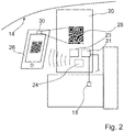
- Fig. 2
- s a schematic view of a monitoring unit installed inside the nacelle of the turbine of
Fig. 1 and of a tablet computer as a portable communication device. -
Figs. 1 and2 illustrate a condition monitoring system and a method according to the invention. The condition monitoring system includes a network of distributedwind turbines 10 as a network of distributed devices to be monitored and acentral control server 12 located in a control room of the network, which may be on the land, whereas theturbines 10 are installed off-shore in this example. - The turbines include a
nacelle 14. Thenacelle 14 is a housing receiving a generator, bearings and transmission gears (not shown) necessary for the operation of theturbine 10 and for generating electricity out of the wind power. - Multiple sensors such as a sensor 18 (
Fig. 2 ) for measuring the temperature of the generator (not shown) as well as other temperature sensors, rotation sensors, vibration sensors and acceleration sensors are mounted at critical points of theturbine 10 inside and/or outside thenacelle 14 for monitoring purposes. - The
sensors 18 are connected to amonitoring unit 20 mounted inside thenacelle 14, which records and processes the sensor signals received from thesensors 18. - The
monitoring unit 20 includes aprocessor 21 capable of performing various signal processing algorithms such as time wave form analysis, vector analysis, real-time Fourier transforms, digital peak enveloping, integration/derivation both in time and frequency domain, Windowing, etc. as well as the possibility to implement user-formulated mathematical equations based on the obtained results. The results are compared with threshold parameters for triggering alarm signals. Cable fault and sensor fault detection systems are also implemented. The sensor input interfaces of themonitoring unit 20 include multiple analog inputs as well as digital inputs. - The
monitoring unit 20 is provided with Ethernet interfaces connected to a communication wire forming acommunication link 22 to thecentral server 12. The communication link uses TCP/IP. - Further, various other interfaces such as an RS 232 service interface for updating the firmware of the
processor 21 of themonitoring unit 20 or for reading out data on a solidstate memory device 23 of the monitoring unit etc. is also provided. The invention proposes to provide, preferably in addition to the above, acommunication interface 24 for connecting aportable communication device 26 to themonitoring unit 20, wherein "connection" means data exchange connection in this context. - The service staff may enter the
nacelle 14 of theturbine 10 in order to execute service and maintenance work on a regular basis. The standard procedure in the prior art is to provide the service workers with checklists, a service schedule or the like on paper, wherein the service worker notes his or her observations on the paper, takes photographs of critical components, wear parts or the like using a portable camera and the thus collected information has to be manually added to a database of the wind turbine system maintained in theserver 12. The checklists or service schedules are prepared before the service worker leaves his office. - The invention proposes that the service workers should use, as a replacement for the paper documents or in addition to these, a
portable communication device 26 such as a tablet computer, a smart phone or a notebook computer. -
Fig. 2 illustrates the case where atablet computer 26 is used as the portable communication device and wherein thecommunication interface 24 is a short-range Bluetooth interface. The expression short-range is to be interpreted in the context of the application so as to safely cover the typical distances of the service worker to the device to be monitored but preferably not overlapping with the range of wireless communication interfaces in neighboring devices to be monitored. Forwind turbines 10, it is sufficient if the signals of thewireless communication interface 24 can be received inside thenacelle 14, at most at the access platform at the bottom of the turbine tower, such that the range should be of the order of the height of the tower. - The
monitoring unit 20 is arranged in a wall-mounted box in the embodiment ofFig. 2 and a computer-readable code 28 in the form of a QR-tag is provided as a sticker on the door of amonitoring unit 20. - Once the service worker enters the range of the
wireless communication interface 24 and theportable communication device 26 carried by him receives the signals ofcommunication interface 24, a dedicated application software installed on theportable communication device 28 notifies the holder of thedevice 26 that wireless access to themonitoring unit 20 is available and gives instructions on how to create the connections. In the alternative, thecommunication interface 26 may start sending signals only upon manual activation by the service staff. These instructions may be provided in a language chosen in the user settings of theportable communication device 26 and include the information that the computer-readable code 28 is provided on the front door of themonitor unit 20 and that the user should scan thecode 28 using a built-incamera 30 of theportable communication device 26 as a scanning device. - Once the computer-
readable code 28 has been scanned, the application software in the portable communication device uses the code scanned by thecamera 30 to generate a password or other kind of access information (encryption keys, user name or the like) for establishing an encrypted data connection with themonitoring device 20 in a fully automated way. - Optionally, the
monitoring device 20 may establish a further new connection to thecentral control server 12 so as to upload and download data files. This direct connection to thecentral control server 12 may require the manual input of additional access information such as user name and/or password by the service worker. - The communication access to the
monitoring unit 20 as described above is highly secure because the computer-readable code 28 is provided in thenacelle 14, which is an access-restricted area which is usually not accessible for unauthorized personnel. In addition, the application software on theportable communication device 26 is mandatory for the establishment of the connection and the computer-readable code 28 is not readable by humans. - Once the data connection to the
central control server 12 is established, updated device information and/or condition data pertaining to theturbine 10 to be maintained or checked is downloaded from thecentral control server 12 to theportable communication device 26 and a service checklist or service schedule is automatically created or updated on thedevice 26. In addition to this, the user is free to specifically request the download of any data of interest in the case where these are not included in the automatic update. The device information and condition data may include long-time trend data, comparisons with other turbines nearby correlation data and other data helping the service worker understand the problems or potential problems of thedevice 10 being checked. Theportable communication device 26 includes a microphone and the possibility to record voice notes or noise of the generator for documentation purposes as well as thecamera 30, which can be used for taking images of parts of interest, e.g. wear parts, damaged parts or the like. Further, notes may be taken in the electronic checklist stored in thedevice 26 or elsewhere. The thus produced data files, i.e. image files, sound files or text files with notes may be uploaded to thecentral control server 12 automatically or upon request by the user. - In one embodiment of the invention, the user is prompted upon saving the file whether or not he wishes to upload the file to the
central control server 12. If he agrees, the data files are transferred to themonitoring unit 20 via thecommunication interface 24 and themonitoring unit 20 creates a data packet with a header including the device identification number identifying theturbine 10 being checked, the time and the date and optionally identification information of the service worker such as his name and corporate affiliation. - Due to the automated upload via the
monitoring unit 20 in combination with a device identification number, appropriate processing thecentral control server 12 is ensured and storing files such as images of oneturbine 10 under the identification number of another turbine may be safely avoided. In this respect, the feature that the communication between theportable communication device 26 and thecontrol server 12 takes place via themonitoring unit 20 and has major advantages. - The upload of data files may be done file by file or in a consolidated way as a packet upon completion of the service or maintenance works.
- The possibility to download data from the central control server opens the possibility to obtain not only real-time data from the
monitoring unit 20 but also long-time trends or comparisons withother turbines 10 nearby which are not available in thelocal monitoring units 20 of the respective devices.
Claims (13)
- Condition monitoring system including a network of distributed devices (10) to be monitored, at least one portable communication device (26) and at least one central control server (12), wherein each of the devices (10) is provided with:a. at least one sensor (18) for measuring condition data of the device (10),b. a monitoring unit (20) for receiving and processing the condition data from the at least one sensor (18),c. a communication link (22) between the monitoring unit (20) and the central control server (12),
wherein:- the monitoring unit (20) is configured to send the processed condition data of the device to the central control server (10) in combination with identification data for identifying the device; and- the central control server (12) is configured to store the condition data in combination said identification data,- the monitoring unit (20) is equipped with a communication interface (24) for connecting the portable communication device (26) to the monitoring unit (20), wherein- the monitoring unit (20) is configured to automatically provide updated condition data to the portable communication device (26) upon establishment of the connection to the monitoring unit (20) and wherein- service information used and displayed on said portable communication device (26) is created or updated based on the updated condition data characterized in that- the service information includes a service schedule or a checklist. - Condition monitoring system according to claim 1, wherein the network of distributed devices (10) includes at least one wind turbine having a nacelle (14), wherein the monitoring unit (20) is arranged in the nacelle (14) of the wind turbine.
- Condition monitoring system according to claim 1 or 2, wherein access information (28) for connecting the portable communication device (26) to the monitoring unit (20) is provided inside the nacelle (14) of the wind turbine.
- Condition monitoring system according one of the preceding claims, wherein the monitoring unit (20) is configured to enable bi-directional data exchange between the central control server (12) and the portable communication device (26) using the communication link (22).
- Condition monitoring system according to one of the preceding claims, wherein said data exchange includes downloading device information form the central control server (12) upon request by the portable communication device (26), wherein the monitoring unit (20) is configured to add the identification data to a download request triggered by the portable communication device (26).
- Condition monitoring system according to claim 5, wherein said data exchange includes uploading data generated by the portable communication device (26) to the central control server (12), wherein the monitoring unit (20) is configured to add the identification data to the uploaded data.
- Condition monitoring system according to one of the preceding claims, wherein the monitoring unit (20) is configured to receive image data from a camera (30) built in the portable communication device (26) or sound data from a means for recording sound files from the portable communication device (26) and to send the image data and/or sound data in combination with identification data for identifying device to the central control server (12).
- Condition monitoring system according to one of the preceding claims, wherein said communication interface (24) is a short-range wireless interface.
- Condition monitoring system according to claim 8, wherein the communication interface (24) is a W-LAN or Bluetooth interface.
- Condition monitoring system according to one of the preceding claims, wherein the communication between the portable communication device (26) and the monitoring unit (20) is encrypted.
- Condition monitoring system according to one of the preceding claims, wherein monitoring unit (20) comprises a buffer memory (23) for storing data to be submitted to the central control server (12) temporarily while the communication link (22) is down.
- Portable communication device (26) for use in a condition monitoring system according to one of the preceding claims, wherein the portable communication device (26) is provided with application software for establishing a communication connection to the monitoring unit (20) and/or the central control server (12) and for receiving updated condition data upon establishment of the connection to the monitoring unit (20) using the communication interface (24) of the monitoring unit (20) wherein service information used and displayed on said portable communication device (26) is created or updated based on the updated condition data, and characterized in that the service information includes a service schedule or checklist.
- Method for servicing devices in a network of distributed devices of a condition monitoring system according to one of the preceding claims, the method including the steps of:a. establishing a communication connection between the portable communication device (26) and the monitoring unit (20) and/or the central control server (12); andb. providing the portable communication device (26) with updated condition data pertaining to the device to be monitored, andc. creating or updating service information based on the updated condition data, characterized in that the service information includes a service schedule or checklist.
Applications Claiming Priority (1)
| Application Number | Priority Date | Filing Date | Title |
|---|---|---|---|
| PCT/EP2013/053066 WO2014124683A1 (en) | 2013-02-15 | 2013-02-15 | Condition monitoring system and method for creating or updating service information |
Publications (2)
| Publication Number | Publication Date |
|---|---|
| EP2956831A1 EP2956831A1 (en) | 2015-12-23 |
| EP2956831B1 true EP2956831B1 (en) | 2019-08-14 |
Family
ID=47716056
Family Applications (1)
| Application Number | Title | Priority Date | Filing Date |
|---|---|---|---|
| EP13704445.9A Active EP2956831B1 (en) | 2013-02-15 | 2013-02-15 | Condition monitoring system and method for creating or updating service information |
Country Status (4)
| Country | Link |
|---|---|
| US (1) | US20150381443A1 (en) |
| EP (1) | EP2956831B1 (en) |
| CN (1) | CN105009011B (en) |
| WO (1) | WO2014124683A1 (en) |
Cited By (3)
| Publication number | Priority date | Publication date | Assignee | Title |
|---|---|---|---|---|
| US11635060B2 (en) | 2021-01-20 | 2023-04-25 | General Electric Company | System for operating a wind turbine using cumulative load histograms based on actual operation thereof |
| US11661919B2 (en) | 2021-01-20 | 2023-05-30 | General Electric Company | Odometer-based control of a wind turbine power system |
| US11728654B2 (en) | 2021-03-19 | 2023-08-15 | General Electric Renovables Espana, S.L. | Systems and methods for operating power generating assets |
Families Citing this family (11)
| Publication number | Priority date | Publication date | Assignee | Title |
|---|---|---|---|---|
| US20120219418A1 (en) * | 2009-11-13 | 2012-08-30 | Schaeffler Technologies AG & Co. KG | Gps automated tracking of mobile monitoring units |
| CN104411968B (en) * | 2012-06-04 | 2018-07-24 | 维斯塔斯风力系统集团公司 | Control system for wind turbine |
| EP2956830A1 (en) * | 2013-02-15 | 2015-12-23 | Aktiebolaget SKF | Condition monitoring system and method data exchange |
| US9877089B2 (en) | 2016-05-13 | 2018-01-23 | Shockwatch, Inc. | Wireless environmental sensor |
| KR101768810B1 (en) | 2016-06-02 | 2017-08-30 | 두산중공업 주식회사 | Wind farm supervision monitoring system |
| IT201700038298A1 (en) * | 2017-04-07 | 2018-10-07 | Cefla Soc Cooperativa | METHOD AND APPARATUS AND FOR THE AUTOMATED MANAGEMENT OF A PAINTING SYSTEM |
| JP6503419B2 (en) | 2017-07-07 | 2019-04-17 | 三菱重工業株式会社 | Data collection system for wind power generation facility, data collection method, and wind power generation facility |
| FI129143B (en) * | 2017-11-03 | 2021-08-13 | Logmore Oy | Data transmission system and use of a data transmission system for monitoring a monitored object |
| DE102018103772A1 (en) * | 2018-02-20 | 2019-08-22 | Dekra Exam Gmbh | Monitoring system for a protective device and protective device |
| US20220191092A1 (en) * | 2019-03-28 | 2022-06-16 | Inventio Ag | Method and system for commissioning of a communication gateway |
| DE102019216406B4 (en) * | 2019-10-24 | 2023-07-20 | Robert Bosch Gmbh | Communication system for monitoring process units |
Family Cites Families (21)
| Publication number | Priority date | Publication date | Assignee | Title |
|---|---|---|---|---|
| US6714895B2 (en) * | 2000-06-28 | 2004-03-30 | A.L. Air Data, Inc. | Lamp monitoring and control unit and method |
| US6730024B2 (en) * | 2000-05-17 | 2004-05-04 | Brava, Llc | Method and apparatus for collecting patient compliance data including processing and display thereof over a computer network |
| US6556956B1 (en) * | 2000-06-30 | 2003-04-29 | General Electric Company | Data acquisition unit for remote monitoring system and method for remote monitoring |
| JP2002111705A (en) * | 2000-10-02 | 2002-04-12 | Mitsubishi Electric Corp | Remote plant monitoring control system |
| US8260896B2 (en) * | 2007-02-02 | 2012-09-04 | Mwa Intelligence, Inc. | Monitoring business machines using a mesh network on field nodes |
| CN100476651C (en) * | 2007-08-23 | 2009-04-08 | 上海交通大学 | Monitoring system for large wind power station on the sea |
| US9244455B2 (en) * | 2007-09-10 | 2016-01-26 | Fisher-Rosemount Systems, Inc. | Location dependent control access in a process control system |
| CN101246367A (en) * | 2008-03-25 | 2008-08-20 | 南京科远控制工程有限公司 | Wind power generation field monitoring system based on real-time data base |
| CA2778216A1 (en) * | 2008-04-24 | 2009-10-29 | Composotech Structures Inc. | A method and system for determining an imbalance of a wind turbine rotor |
| US8583602B2 (en) * | 2008-06-05 | 2013-11-12 | Palm, Inc. | Restoring of data to mobile computing device |
| GB2472977B (en) * | 2009-08-24 | 2011-12-07 | Dale Read | A monitoring unit |
| US20100280872A1 (en) * | 2009-08-27 | 2010-11-04 | Scholte-Wassink Hartmut | Methods and systems for monitoring and scheduling operations and maintenance activities |
| US7948103B2 (en) * | 2009-09-03 | 2011-05-24 | General Electric Company | Method and system for verifying wind turbine operation |
| US20120299747A1 (en) * | 2009-11-13 | 2012-11-29 | Schaeffler Technologies AG & Co. KG | Remote condition monitoring system and method |
| US20120219418A1 (en) * | 2009-11-13 | 2012-08-30 | Schaeffler Technologies AG & Co. KG | Gps automated tracking of mobile monitoring units |
| CN102235941A (en) * | 2010-04-29 | 2011-11-09 | 上海瑞视仪表电子有限公司 | State monitoring and failure diagnosing system for wind power generation units |
| US20120035749A1 (en) * | 2010-08-04 | 2012-02-09 | Fisher-Rosemount Systems, Inc. | Seamless integration of process control devices in a process control environment |
| CN102802155A (en) * | 2012-08-17 | 2012-11-28 | 珠海金山办公软件有限公司 | Method for rapidly establishing connection between mobile terminal and intelligent display equipment |
| EP2956830A1 (en) * | 2013-02-15 | 2015-12-23 | Aktiebolaget SKF | Condition monitoring system and method data exchange |
| CN104981745A (en) * | 2013-02-15 | 2015-10-14 | 斯凯孚公司 | Condition monitoring system and access control therefore |
| CN203799239U (en) * | 2014-03-04 | 2014-08-27 | 杭州海勒科技有限公司 | Remote wireless monitoring system for diesel generator set |
-
2013
- 2013-02-15 WO PCT/EP2013/053066 patent/WO2014124683A1/en active Application Filing
- 2013-02-15 CN CN201380072128.2A patent/CN105009011B/en active Active
- 2013-02-15 US US14/765,845 patent/US20150381443A1/en not_active Abandoned
- 2013-02-15 EP EP13704445.9A patent/EP2956831B1/en active Active
Non-Patent Citations (1)
| Title |
|---|
| None * |
Cited By (3)
| Publication number | Priority date | Publication date | Assignee | Title |
|---|---|---|---|---|
| US11635060B2 (en) | 2021-01-20 | 2023-04-25 | General Electric Company | System for operating a wind turbine using cumulative load histograms based on actual operation thereof |
| US11661919B2 (en) | 2021-01-20 | 2023-05-30 | General Electric Company | Odometer-based control of a wind turbine power system |
| US11728654B2 (en) | 2021-03-19 | 2023-08-15 | General Electric Renovables Espana, S.L. | Systems and methods for operating power generating assets |
Also Published As
| Publication number | Publication date |
|---|---|
| CN105009011B (en) | 2020-08-28 |
| EP2956831A1 (en) | 2015-12-23 |
| CN105009011A (en) | 2015-10-28 |
| US20150381443A1 (en) | 2015-12-31 |
| WO2014124683A1 (en) | 2014-08-21 |
Similar Documents
| Publication | Publication Date | Title |
|---|---|---|
| EP2956831B1 (en) | Condition monitoring system and method for creating or updating service information | |
| US20150377214A1 (en) | Condition monitoring system and access control therefore | |
| US20150370236A1 (en) | Condition monitoring system and method data exchange | |
| US20160080902A1 (en) | Mobile communication device including positioning means and method for using positioning coordinates to automatically serve service personnel with machine service information | |
| US20180182179A1 (en) | Comprehensive system and method for real-time monitoring and management of security patrolling operations | |
| CN103782602B (en) | Remotely display | |
| CN101223548B (en) | System for making report with authenticated image | |
| KR101869697B1 (en) | Managing system power plant using the internet of things and the method thereof | |
| US20170280107A1 (en) | Site sentinel systems and methods | |
| CN204965565U (en) | Access control system of transformer substation | |
| KR101628269B1 (en) | Power Plant Field Monitoring System and Method by using QR code | |
| US10430041B2 (en) | Information collection system, information collection terminal device, information collection server, and information collection method | |
| CN108063492A (en) | A kind of integrated system and application process of anti-work of combating typhoon of power grid | |
| KR101480784B1 (en) | River Facility Maintenance Method using Near Field Communication | |
| JP2015106391A (en) | Maintenance and inspection system | |
| JP6248985B2 (en) | Information search system and information search method | |
| CN109587448A (en) | A kind of intelligent substation inspection tour system | |
| KR20130049221A (en) | Patrol supporting system and method based on a code, apparatus and portable device supporting the same | |
| US11937022B2 (en) | Intelligent electronic device having user-authenticating capabilities | |
| EP2933696A1 (en) | Mobile human machine interface for control devices | |
| TW201928891A (en) | Patrol service system and verification method used therein | |
| KR100751030B1 (en) | System for protecting privacy and method therefor | |
| JP2005284350A (en) | Facility operation management system and facility operation management method | |
| CN106341439B (en) | System for managing the instant job information of zero lens of motor | |
| US20230032383A1 (en) | Apparatus and system for use with an operation |
Legal Events
| Date | Code | Title | Description |
|---|---|---|---|
| PUAI | Public reference made under article 153(3) epc to a published international application that has entered the european phase |
Free format text: ORIGINAL CODE: 0009012 |
|
| 17P | Request for examination filed |
Effective date: 20150804 |
|
| AK | Designated contracting states |
Kind code of ref document: A1 Designated state(s): AL AT BE BG CH CY CZ DE DK EE ES FI FR GB GR HR HU IE IS IT LI LT LU LV MC MK MT NL NO PL PT RO RS SE SI SK SM TR |
|
| AX | Request for extension of the european patent |
Extension state: BA ME |
|
| DAX | Request for extension of the european patent (deleted) | ||
| STAA | Information on the status of an ep patent application or granted ep patent |
Free format text: STATUS: EXAMINATION IS IN PROGRESS |
|
| 17Q | First examination report despatched |
Effective date: 20180508 |
|
| GRAP | Despatch of communication of intention to grant a patent |
Free format text: ORIGINAL CODE: EPIDOSNIGR1 |
|
| STAA | Information on the status of an ep patent application or granted ep patent |
Free format text: STATUS: GRANT OF PATENT IS INTENDED |
|
| RIC1 | Information provided on ipc code assigned before grant |
Ipc: F03D 17/00 20160101ALI20190204BHEP Ipc: G05B 23/02 20060101AFI20190204BHEP |
|
| INTG | Intention to grant announced |
Effective date: 20190304 |
|
| GRAS | Grant fee paid |
Free format text: ORIGINAL CODE: EPIDOSNIGR3 |
|
| GRAA | (expected) grant |
Free format text: ORIGINAL CODE: 0009210 |
|
| STAA | Information on the status of an ep patent application or granted ep patent |
Free format text: STATUS: THE PATENT HAS BEEN GRANTED |
|
| AK | Designated contracting states |
Kind code of ref document: B1 Designated state(s): AL AT BE BG CH CY CZ DE DK EE ES FI FR GB GR HR HU IE IS IT LI LT LU LV MC MK MT NL NO PL PT RO RS SE SI SK SM TR |
|
| REG | Reference to a national code |
Ref country code: GB Ref legal event code: FG4D |
|
| REG | Reference to a national code |
Ref country code: CH Ref legal event code: EP Ref country code: AT Ref legal event code: REF Ref document number: 1167759 Country of ref document: AT Kind code of ref document: T Effective date: 20190815 |
|
| REG | Reference to a national code |
Ref country code: IE Ref legal event code: FG4D |
|
| REG | Reference to a national code |
Ref country code: DE Ref legal event code: R096 Ref document number: 602013059103 Country of ref document: DE |
|
| REG | Reference to a national code |
Ref country code: NL Ref legal event code: MP Effective date: 20190814 |
|
| REG | Reference to a national code |
Ref country code: LT Ref legal event code: MG4D |
|
| PG25 | Lapsed in a contracting state [announced via postgrant information from national office to epo] |
Ref country code: NO Free format text: LAPSE BECAUSE OF FAILURE TO SUBMIT A TRANSLATION OF THE DESCRIPTION OR TO PAY THE FEE WITHIN THE PRESCRIBED TIME-LIMIT Effective date: 20191114 Ref country code: PT Free format text: LAPSE BECAUSE OF FAILURE TO SUBMIT A TRANSLATION OF THE DESCRIPTION OR TO PAY THE FEE WITHIN THE PRESCRIBED TIME-LIMIT Effective date: 20191216 Ref country code: HR Free format text: LAPSE BECAUSE OF FAILURE TO SUBMIT A TRANSLATION OF THE DESCRIPTION OR TO PAY THE FEE WITHIN THE PRESCRIBED TIME-LIMIT Effective date: 20190814 Ref country code: SE Free format text: LAPSE BECAUSE OF FAILURE TO SUBMIT A TRANSLATION OF THE DESCRIPTION OR TO PAY THE FEE WITHIN THE PRESCRIBED TIME-LIMIT Effective date: 20190814 Ref country code: FI Free format text: LAPSE BECAUSE OF FAILURE TO SUBMIT A TRANSLATION OF THE DESCRIPTION OR TO PAY THE FEE WITHIN THE PRESCRIBED TIME-LIMIT Effective date: 20190814 Ref country code: LT Free format text: LAPSE BECAUSE OF FAILURE TO SUBMIT A TRANSLATION OF THE DESCRIPTION OR TO PAY THE FEE WITHIN THE PRESCRIBED TIME-LIMIT Effective date: 20190814 Ref country code: NL Free format text: LAPSE BECAUSE OF FAILURE TO SUBMIT A TRANSLATION OF THE DESCRIPTION OR TO PAY THE FEE WITHIN THE PRESCRIBED TIME-LIMIT Effective date: 20190814 Ref country code: BG Free format text: LAPSE BECAUSE OF FAILURE TO SUBMIT A TRANSLATION OF THE DESCRIPTION OR TO PAY THE FEE WITHIN THE PRESCRIBED TIME-LIMIT Effective date: 20191114 |
|
| REG | Reference to a national code |
Ref country code: AT Ref legal event code: MK05 Ref document number: 1167759 Country of ref document: AT Kind code of ref document: T Effective date: 20190814 |
|
| PG25 | Lapsed in a contracting state [announced via postgrant information from national office to epo] |
Ref country code: GR Free format text: LAPSE BECAUSE OF FAILURE TO SUBMIT A TRANSLATION OF THE DESCRIPTION OR TO PAY THE FEE WITHIN THE PRESCRIBED TIME-LIMIT Effective date: 20191115 Ref country code: AL Free format text: LAPSE BECAUSE OF FAILURE TO SUBMIT A TRANSLATION OF THE DESCRIPTION OR TO PAY THE FEE WITHIN THE PRESCRIBED TIME-LIMIT Effective date: 20190814 Ref country code: ES Free format text: LAPSE BECAUSE OF FAILURE TO SUBMIT A TRANSLATION OF THE DESCRIPTION OR TO PAY THE FEE WITHIN THE PRESCRIBED TIME-LIMIT Effective date: 20190814 Ref country code: LV Free format text: LAPSE BECAUSE OF FAILURE TO SUBMIT A TRANSLATION OF THE DESCRIPTION OR TO PAY THE FEE WITHIN THE PRESCRIBED TIME-LIMIT Effective date: 20190814 Ref country code: RS Free format text: LAPSE BECAUSE OF FAILURE TO SUBMIT A TRANSLATION OF THE DESCRIPTION OR TO PAY THE FEE WITHIN THE PRESCRIBED TIME-LIMIT Effective date: 20190814 Ref country code: IS Free format text: LAPSE BECAUSE OF FAILURE TO SUBMIT A TRANSLATION OF THE DESCRIPTION OR TO PAY THE FEE WITHIN THE PRESCRIBED TIME-LIMIT Effective date: 20191214 |
|
| PG25 | Lapsed in a contracting state [announced via postgrant information from national office to epo] |
Ref country code: TR Free format text: LAPSE BECAUSE OF FAILURE TO SUBMIT A TRANSLATION OF THE DESCRIPTION OR TO PAY THE FEE WITHIN THE PRESCRIBED TIME-LIMIT Effective date: 20190814 |
|
| PG25 | Lapsed in a contracting state [announced via postgrant information from national office to epo] |
Ref country code: PL Free format text: LAPSE BECAUSE OF FAILURE TO SUBMIT A TRANSLATION OF THE DESCRIPTION OR TO PAY THE FEE WITHIN THE PRESCRIBED TIME-LIMIT Effective date: 20190814 Ref country code: EE Free format text: LAPSE BECAUSE OF FAILURE TO SUBMIT A TRANSLATION OF THE DESCRIPTION OR TO PAY THE FEE WITHIN THE PRESCRIBED TIME-LIMIT Effective date: 20190814 Ref country code: RO Free format text: LAPSE BECAUSE OF FAILURE TO SUBMIT A TRANSLATION OF THE DESCRIPTION OR TO PAY THE FEE WITHIN THE PRESCRIBED TIME-LIMIT Effective date: 20190814 Ref country code: IT Free format text: LAPSE BECAUSE OF FAILURE TO SUBMIT A TRANSLATION OF THE DESCRIPTION OR TO PAY THE FEE WITHIN THE PRESCRIBED TIME-LIMIT Effective date: 20190814 Ref country code: AT Free format text: LAPSE BECAUSE OF FAILURE TO SUBMIT A TRANSLATION OF THE DESCRIPTION OR TO PAY THE FEE WITHIN THE PRESCRIBED TIME-LIMIT Effective date: 20190814 Ref country code: DK Free format text: LAPSE BECAUSE OF FAILURE TO SUBMIT A TRANSLATION OF THE DESCRIPTION OR TO PAY THE FEE WITHIN THE PRESCRIBED TIME-LIMIT Effective date: 20190814 |
|
| PG25 | Lapsed in a contracting state [announced via postgrant information from national office to epo] |
Ref country code: IS Free format text: LAPSE BECAUSE OF FAILURE TO SUBMIT A TRANSLATION OF THE DESCRIPTION OR TO PAY THE FEE WITHIN THE PRESCRIBED TIME-LIMIT Effective date: 20200224 Ref country code: SM Free format text: LAPSE BECAUSE OF FAILURE TO SUBMIT A TRANSLATION OF THE DESCRIPTION OR TO PAY THE FEE WITHIN THE PRESCRIBED TIME-LIMIT Effective date: 20190814 Ref country code: SK Free format text: LAPSE BECAUSE OF FAILURE TO SUBMIT A TRANSLATION OF THE DESCRIPTION OR TO PAY THE FEE WITHIN THE PRESCRIBED TIME-LIMIT Effective date: 20190814 Ref country code: CZ Free format text: LAPSE BECAUSE OF FAILURE TO SUBMIT A TRANSLATION OF THE DESCRIPTION OR TO PAY THE FEE WITHIN THE PRESCRIBED TIME-LIMIT Effective date: 20190814 |
|
| REG | Reference to a national code |
Ref country code: DE Ref legal event code: R097 Ref document number: 602013059103 Country of ref document: DE |
|
| PLBE | No opposition filed within time limit |
Free format text: ORIGINAL CODE: 0009261 |
|
| STAA | Information on the status of an ep patent application or granted ep patent |
Free format text: STATUS: NO OPPOSITION FILED WITHIN TIME LIMIT |
|
| PG2D | Information on lapse in contracting state deleted |
Ref country code: IS |
|
| 26N | No opposition filed |
Effective date: 20200603 |
|
| PG25 | Lapsed in a contracting state [announced via postgrant information from national office to epo] |
Ref country code: SI Free format text: LAPSE BECAUSE OF FAILURE TO SUBMIT A TRANSLATION OF THE DESCRIPTION OR TO PAY THE FEE WITHIN THE PRESCRIBED TIME-LIMIT Effective date: 20190814 |
|
| REG | Reference to a national code |
Ref country code: CH Ref legal event code: PL |
|
| GBPC | Gb: european patent ceased through non-payment of renewal fee |
Effective date: 20200215 |
|
| REG | Reference to a national code |
Ref country code: BE Ref legal event code: MM Effective date: 20200229 |
|
| PG25 | Lapsed in a contracting state [announced via postgrant information from national office to epo] |
Ref country code: LU Free format text: LAPSE BECAUSE OF NON-PAYMENT OF DUE FEES Effective date: 20200215 Ref country code: MC Free format text: LAPSE BECAUSE OF FAILURE TO SUBMIT A TRANSLATION OF THE DESCRIPTION OR TO PAY THE FEE WITHIN THE PRESCRIBED TIME-LIMIT Effective date: 20190814 |
|
| PG25 | Lapsed in a contracting state [announced via postgrant information from national office to epo] |
Ref country code: LI Free format text: LAPSE BECAUSE OF NON-PAYMENT OF DUE FEES Effective date: 20200229 Ref country code: CH Free format text: LAPSE BECAUSE OF NON-PAYMENT OF DUE FEES Effective date: 20200229 |
|
| PG25 | Lapsed in a contracting state [announced via postgrant information from national office to epo] |
Ref country code: GB Free format text: LAPSE BECAUSE OF NON-PAYMENT OF DUE FEES Effective date: 20200215 Ref country code: IE Free format text: LAPSE BECAUSE OF NON-PAYMENT OF DUE FEES Effective date: 20200215 |
|
| PG25 | Lapsed in a contracting state [announced via postgrant information from national office to epo] |
Ref country code: BE Free format text: LAPSE BECAUSE OF NON-PAYMENT OF DUE FEES Effective date: 20200229 |
|
| PG25 | Lapsed in a contracting state [announced via postgrant information from national office to epo] |
Ref country code: MT Free format text: LAPSE BECAUSE OF FAILURE TO SUBMIT A TRANSLATION OF THE DESCRIPTION OR TO PAY THE FEE WITHIN THE PRESCRIBED TIME-LIMIT Effective date: 20190814 Ref country code: CY Free format text: LAPSE BECAUSE OF FAILURE TO SUBMIT A TRANSLATION OF THE DESCRIPTION OR TO PAY THE FEE WITHIN THE PRESCRIBED TIME-LIMIT Effective date: 20190814 |
|
| PG25 | Lapsed in a contracting state [announced via postgrant information from national office to epo] |
Ref country code: MK Free format text: LAPSE BECAUSE OF FAILURE TO SUBMIT A TRANSLATION OF THE DESCRIPTION OR TO PAY THE FEE WITHIN THE PRESCRIBED TIME-LIMIT Effective date: 20190814 |
|
| P01 | Opt-out of the competence of the unified patent court (upc) registered |
Effective date: 20230513 |
|
| PGFP | Annual fee paid to national office [announced via postgrant information from national office to epo] |
Ref country code: DE Payment date: 20240228 Year of fee payment: 12 |
|
| PGFP | Annual fee paid to national office [announced via postgrant information from national office to epo] |
Ref country code: FR Payment date: 20240226 Year of fee payment: 12 |