EP2956710B1 - Luminaire allongé - Google Patents
Luminaire allongé Download PDFInfo
- Publication number
- EP2956710B1 EP2956710B1 EP14716246.5A EP14716246A EP2956710B1 EP 2956710 B1 EP2956710 B1 EP 2956710B1 EP 14716246 A EP14716246 A EP 14716246A EP 2956710 B1 EP2956710 B1 EP 2956710B1
- Authority
- EP
- European Patent Office
- Prior art keywords
- cover
- layer
- luminaire
- carrier
- light
- Prior art date
- Legal status (The legal status is an assumption and is not a legal conclusion. Google has not performed a legal analysis and makes no representation as to the accuracy of the status listed.)
- Active
Links
- 239000004033 plastic Substances 0.000 claims description 8
- 229920003023 plastic Polymers 0.000 claims description 8
- 229910052751 metal Inorganic materials 0.000 claims description 7
- 239000002184 metal Substances 0.000 claims description 7
- 229920003229 poly(methyl methacrylate) Polymers 0.000 claims description 4
- 239000004926 polymethyl methacrylate Substances 0.000 claims description 4
- 239000004922 lacquer Substances 0.000 claims description 3
- 238000001816 cooling Methods 0.000 claims 1
- 229910052782 aluminium Inorganic materials 0.000 description 3
- XAGFODPZIPBFFR-UHFFFAOYSA-N aluminium Chemical compound [Al] XAGFODPZIPBFFR-UHFFFAOYSA-N 0.000 description 3
- 238000009826 distribution Methods 0.000 description 2
- 239000011888 foil Substances 0.000 description 2
- 239000000725 suspension Substances 0.000 description 2
- 238000000149 argon plasma sintering Methods 0.000 description 1
- 239000011248 coating agent Substances 0.000 description 1
- 238000000576 coating method Methods 0.000 description 1
- 230000001419 dependent effect Effects 0.000 description 1
- 238000010586 diagram Methods 0.000 description 1
- 230000000694 effects Effects 0.000 description 1
- 238000004049 embossing Methods 0.000 description 1
- 239000011521 glass Substances 0.000 description 1
- 238000003475 lamination Methods 0.000 description 1
- 238000004519 manufacturing process Methods 0.000 description 1
- 239000000463 material Substances 0.000 description 1
- 230000003287 optical effect Effects 0.000 description 1
- 230000002093 peripheral effect Effects 0.000 description 1
- 230000001681 protective effect Effects 0.000 description 1
- 238000004904 shortening Methods 0.000 description 1
- 229920001169 thermoplastic Polymers 0.000 description 1
- 239000004416 thermosoftening plastic Substances 0.000 description 1
Images


Classifications
-
- F—MECHANICAL ENGINEERING; LIGHTING; HEATING; WEAPONS; BLASTING
- F21—LIGHTING
- F21S—NON-PORTABLE LIGHTING DEVICES; SYSTEMS THEREOF; VEHICLE LIGHTING DEVICES SPECIALLY ADAPTED FOR VEHICLE EXTERIORS
- F21S4/00—Lighting devices or systems using a string or strip of light sources
- F21S4/20—Lighting devices or systems using a string or strip of light sources with light sources held by or within elongate supports
- F21S4/28—Lighting devices or systems using a string or strip of light sources with light sources held by or within elongate supports rigid, e.g. LED bars
-
- F—MECHANICAL ENGINEERING; LIGHTING; HEATING; WEAPONS; BLASTING
- F21—LIGHTING
- F21V—FUNCTIONAL FEATURES OR DETAILS OF LIGHTING DEVICES OR SYSTEMS THEREOF; STRUCTURAL COMBINATIONS OF LIGHTING DEVICES WITH OTHER ARTICLES, NOT OTHERWISE PROVIDED FOR
- F21V3/00—Globes; Bowls; Cover glasses
- F21V3/04—Globes; Bowls; Cover glasses characterised by materials, surface treatments or coatings
- F21V3/06—Globes; Bowls; Cover glasses characterised by materials, surface treatments or coatings characterised by the material
- F21V3/062—Globes; Bowls; Cover glasses characterised by materials, surface treatments or coatings characterised by the material the material being plastics
- F21V3/0625—Globes; Bowls; Cover glasses characterised by materials, surface treatments or coatings characterised by the material the material being plastics the material diffusing light, e.g. translucent plastics
-
- F—MECHANICAL ENGINEERING; LIGHTING; HEATING; WEAPONS; BLASTING
- F21—LIGHTING
- F21V—FUNCTIONAL FEATURES OR DETAILS OF LIGHTING DEVICES OR SYSTEMS THEREOF; STRUCTURAL COMBINATIONS OF LIGHTING DEVICES WITH OTHER ARTICLES, NOT OTHERWISE PROVIDED FOR
- F21V3/00—Globes; Bowls; Cover glasses
- F21V3/04—Globes; Bowls; Cover glasses characterised by materials, surface treatments or coatings
- F21V3/10—Globes; Bowls; Cover glasses characterised by materials, surface treatments or coatings characterised by coatings
-
- F—MECHANICAL ENGINEERING; LIGHTING; HEATING; WEAPONS; BLASTING
- F21—LIGHTING
- F21Y—INDEXING SCHEME ASSOCIATED WITH SUBCLASSES F21K, F21L, F21S and F21V, RELATING TO THE FORM OR THE KIND OF THE LIGHT SOURCES OR OF THE COLOUR OF THE LIGHT EMITTED
- F21Y2105/00—Planar light sources
- F21Y2105/10—Planar light sources comprising a two-dimensional array of point-like light-generating elements
-
- F—MECHANICAL ENGINEERING; LIGHTING; HEATING; WEAPONS; BLASTING
- F21—LIGHTING
- F21Y—INDEXING SCHEME ASSOCIATED WITH SUBCLASSES F21K, F21L, F21S and F21V, RELATING TO THE FORM OR THE KIND OF THE LIGHT SOURCES OR OF THE COLOUR OF THE LIGHT EMITTED
- F21Y2115/00—Light-generating elements of semiconductor light sources
- F21Y2115/10—Light-emitting diodes [LED]
Definitions
- the invention relates to an elongated lamp.
- the Applicant sells an elongated luminaire under the name SLOTLIGHT II.
- This luminaire comprises a profile-like, in cross-section in a first approximation U-shaped, aluminum channel element and an elongated, translucent plastic cover which is snapped into the channel element and through which a plane, light-emitting Surface of the lamp is formed.
- an end cap is placed in each case.
- the end caps serve to conceal these different longitudinal changes.
- the end caps also lead to the appearance of the luminaire when viewed on the light-emitting surface edge is uneven.
- the longitudinal edges of the light-emitting surface appear differently than the front edges of the end caps.
- the lamp From the DE 81 28 057 U1 is a lamp with a, a light exit opening occlusive diffuser wall and a housing side wall known. Furthermore, the lamp has a housing rear side, which is fastened to the housing side walls.
- the housing side walls are made of a plastic and are provided with a reflective layer.
- thermoplastic sheet for use as a light scattering protective cover for LED light sources.
- FR 2 122 501 A1 From the FR 2 122 501 A1 is an elongated lamp with a support and a cover known.
- the cover has a laterally encircling wall portion and at its upper edge grooves which engage for support in ribs formed on the support.
- the invention has for its object to provide an elongated lamp that allows a particularly uniform appearance.
- the luminaire is intended to make it possible that, when viewing the light-emitting surface, the edge of this surface appears to be particularly uniform all around.
- a luminaire having an elongated cover with a planar light emission surface extending in a plane, and an elongated support, the cover being mounted on the support.
- the cover has a lateral wall area, which is closed circumferential shape immediately adjoins the light emitting surface. In this case, a light-tight layer is applied to the lateral wall region.
- the cover is made of plastic and the support of metal.
- the edge of the light emission surface has a uniform appearance on all sides; there are no end caps required, because due to the lateral wall portion of the carrier does not have to extend to the light emitting surface. Due to the light-tight layer on the lateral wall area, the edge can be made to appear particularly clear and precise. It can almost cause a "frameless" appearing light delivery surface.
- the layer consists of a metal and the cover for example of PMMA (polymethyl methacrylate).
- PMMA polymethyl methacrylate
- the layer is formed by a film and / or by a lacquer.
- the layer can be made very thin and thus the edge of the light emitting surface defined particularly sharp, so to speak, like a line.
- the layer may be formed by coextrusion with the cover.
- the layer is designed to be reflective. As a result, a particularly good efficiency can be achieved for the lamp.
- the cover is shaped so that the side wall portion and the light emitting surface enclose an angle of 90 ° on all sides. This makes it possible to achieve that, when the luminaire is viewed against the normal of the light emission surface, only the light emission surface is visible. This can cause a particularly high-quality impression of the lamp.
- the cover is shaped so that a parallelepiped shape is defined by the light emitting surface and the lateral wall portion.
- the light emission surface can be designed in a particularly straight shape in the form of a straight line.
- the lamp is designed such that the carrier is completely covered by the cover when viewing the lamp against the normal of the light emitting surface. This also makes it possible to make the outer appearance of the lamp advantageous particularly high-quality acting.
- the cover is slidably suspended on the carrier.
- a light source in particular in the form of LEDs (LED: light emitting diode) is supported on the support, wherein the lamp is designed so that a light emitted from the light source passes through the light emitting surface and is discharged into an outer space of the lamp.
- LED light emitting diode
- the carrier forms a surface region of the lamp, wherein in particular the carrier is designed as a heat sink for the light source of the lamp.
- the cover is formed in the region of the light emission surface with a first layer and a second layer, the first layer being diffuse and the second layer being clear.
- the first layer and the second layer are advantageously formed by coextrusion.
- the luminaire has a length which is greater than 3 m, in particular greater than 5 m.
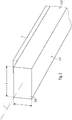
- Fig. 1 shows a perspective sketch of a longitudinal region of a lamp according to the invention.
- the luminaire is overall elongated, so that it extends along a longitudinal axis L.
- the luminaire has an elongate cover 2 which extends along the longitudinal axis L.
- Fig. 5 is shown a sketch to a cross section normal to the longitudinal axis.
- the cover 2 has a light emitting surface 21 which is flat and extends in a plane E.
- the cover 2 is preferably formed in one piece. In this way, the light emission surface 21 can be designed quasi "seamlessly", in particular over the entire longitudinal extension of the cover 2.
- the plane E extends horizontally when the luminaire is aligned, as intended for operation relative to the vertical, with the cover 2 extending from the plane E upwards.
- this orientation of the luminaire is assumed below. In general, however, the luminaire can also be oriented elsewhere.
- the lamp has an elongate carrier 3, which also extends along the longitudinal axis L, wherein the cover 2 is arranged supported on the carrier 3.
- the cover 2 is made of a plastic, such as PMMA.
- the carrier 3 consists of a metal, for example aluminum.
- the lamp is designed very long, so more than three meters, preferably more than five meters. For example, it has a length of up to eight meters. The longer the luminaire is, the more the length changes that are caused by temperature fluctuations generally have an effect.
- the cover 2 extends over the entire length of the lamp while the carrier 3 is slightly shorter than the cover 2 is designed.
- FIG. 2 and 3 two perspective views are sketched on an end portion of the lamp.
- the design is preferably such that with respect to the longitudinal axis L, the cover 2 extends beyond the support 3 at its two end regions. This makes it possible that in the case of a temperature-related shortening of the cover 2 does not happen that - when viewing the lamp against the normal of the light emitting surface 21, so as in Fig. 5 indicated by an arrow p - the carrier 3 is visible at one of the two end portions.
- the cover 2 also has a lateral wall region 22, which adjoins the light emission surface 21 in a closed circumferential shape.
- the cover 2 is shaped such that the lateral wall region 22 and the light emission surface 21 enclose an angle of 90 ° on all sides.
- the cover 2 is preferably shaped such that a parallelepiped shape is defined by the light emission surface 21 and the lateral wall region 22.
- the design may be, for example, such that the cuboid or the cover 2 has a width b measured transversely to the longitudinal axis L , which is between 50 mm and 200 mm, that is, for example 100 mm, and one perpendicular to the longitudinal axis L and to the direction of the width b standing height h, which is between 30 mm and 150 mm, so for example 50 mm or 60 mm.
- the design is furthermore such that the support 3 also extends less far with respect to the width b than the cover 2, so that the cover 2 also extends beyond the support 3 along this widthwise extension.
- the lamp is designed so that the carrier 3 is completely covered by the cover 2 when viewing the lamp normal to or to the light emitting surface 21.
- the carrier 3 is concentrically offset with respect to the cover 2 inwards.
- the lamp is further designed so that in the above-mentioned consideration of the lamp, no other parts of the luminaire next to the light emitting surface 21 are visible.
- a light-tight layer 4 is applied on the lateral wall portion 22, a light-tight layer 4 is applied.
- the layer 4 is preferably designed to form a peripheral edge of the light emitting surface 21.
- the layer 4 thus extends annularly closed along the entire lateral wall region 22.
- the design is such that the lateral wall region 22 is completely covered by the layer 4.
- the layer 4 extends advantageously over the entire height h, the entire width b and the entire Length of the cover 2.
- the layer 4 extends over all vertical wall portions of the cover 2.
- a light-tight lamination can be formed by the layer 4.
- the layer 4 may be formed for example by a film, in particular by a metal foil.
- the film can be applied to the lateral wall region 22, for example, by means of a foil embossing.
- the layer 4 may be formed by a lacquer, in particular in the form of a permanently elastic coating.
- the layer 4 may be formed together with the cover 2 by a coextrusion, so that in this way a quasi, a light-tight side web is formed.
- the layer 4 is designed such that it has a particularly low thickness so as to be able to make the edge of the light emitting surface 21 particularly sharp.
- a light source 5 is supported on the carrier 3.
- the light source 5 may in particular be a plurality of LEDs, which is preferably arranged in a matrix-like manner on a circuit board, which in turn is supported on the carrier 3, in particular with good heat conductivity.
- the luminaire is designed such that a light emitted by the light source 5 passes through the light emission surface 21 and is emitted into an exterior space of the luminaire.
- the light source 5 preferably represents a light source 5 for emitting light of the lamp.
- the layer 4 is designed so that it is reflective, in particular on its inner side, ie on the side facing a center of the cover 2.
- a particularly good efficiency can be achieved for the lamp.
- the carrier 3 is preferably designed so that it forms a surface region of the lamp. In particular, it can be designed as a heat sink for the light source 5.
- the cover 2 is slidably suspended from the carrier as indicated in FIG Fig. 5 shown.
- the cover 2 preferably has an inwardly facing flange region 23 at the upper edge of the lateral wall region 21, which are configured as bearing surfaces of the cover 2 for mounting on the carrier 3 along the regions which extend parallel to the longitudinal axis L. like this Fig. 6 suggestively.
- the flange region 23 only reaches as far as the carrier 3, but does not overlap it. This goes out Fig. 4 which shows a longitudinal section through the end of the lamp.
- the shape of the cover 2 can accordingly describe a total of an elongated cuboid, wherein one of the four longitudinal sides, here the upwardly facing longitudinal side, has a particular rectangular opening, which is designed for suspension on the support 3.
- At least one further lighting component for example an operating device 6 for operating the light source 5, may also be supported on the carrier 3.
- a suspension element for suspending the luminaire, for example on a ceiling, may also be provided or formed on the support 3.
- a particularly suitable light distribution on the light-emitting surface 21 can be achieved if the cover 2 is formed in the area of the light-emitting surface 21 with a first layer 211 and a second layer 212, the first layer 211 being diffuse and the second layer 212 being clear.
- the diffuse or first layer 211 may form an inner layer with respect to the center of the cover 2 and the clear or second layer 212 an outer layer.
- the first layer 211 and the second layer 212 can be formed by coextrusion for this purpose.
- the lateral wall region 22 or the remaining cover 2 may have the same material properties or optical properties as the first layer 211.
- the two mentioned layers 211, 212 may also be formed separately from one another.
- the luminaire is suitable, for example, for being installed in a ceiling with a circumferential shadow gap.
- the shadow gap can be very narrow, for example, only 13 mm.
- the light-emitting surface 21 can therefore be designed very precisely.
- the luminaire allows, as it were, a frameless appearance of the light emission surface 21.
Landscapes
- Engineering & Computer Science (AREA)
- General Engineering & Computer Science (AREA)
- Non-Portable Lighting Devices Or Systems Thereof (AREA)
Claims (12)
- Luminaire comprenant- un couvercle allongé (2) avec une surface d'émission de lumière (21) plane s'étendant dans un plan (E) et- un support allongé (3), le couvercle (2) étant maintenu sur le support (3),le couvercle (2) comprenant une partie de paroi latérale (22) qui se raccorde, sous une forme circulaire fermée, directement à la surface d'émission de lumière (21),
une couche opaque à la lumière (4) étant appliquée à partie de paroi latérale (22),
caractérisé en ce que
le couvercle (2) est suspendu de manière coulissante au support (3),
le couvercle (2) étant constitué d'une matière plastique et le support (3) de métal,
le luminaire présentant une longueur supérieure à 3 m. - Luminaire selon la revendication 1,
dans lequel la couche (4) est constituée d'un métal et le couvercle (2) est constitué par exemple de PMMA. - Luminaire selon la revendication 1 ou 2,
dans lequel la couche (4) est constituée d'un film et/ou d'une peinture ou est formée par coextrusion conjointement avec le couvercle (2). - Luminaire selon l'une des revendications précédentes,
dans lequel la couche (4) est conçue de façon à être réfléchissante. - Luminaire selon l'une des revendications précédentes,
dans lequel le couvercle (2) est formé de façon à ce que la partie de paroi latérale (22) et la surface d'émission de lumière (21) forment de tous les côtés un angle de 90°. - Luminaire selon l'une des revendications précédentes,
dans lequel le couvercle (2) est formé de façon à ce qu'une forme parallélépipédique est définie par la surface d'émission de lumière (21) et la partie de paroi latérale (22). - Luminaire selon l'une des revendications précédentes,
qui est conçu de façon à ce que le support (3) soit recouvert entièrement par le couvercle (2) lors d'une observation du luminaire de manière perpendiculaire à la surface d'émission de lumière (21). - Luminaire selon l'une des revendications précédentes,
dans lequel, sur le support (3), est maintenue une source de lumière (5), plus particulièrement sous la forme de LED, le luminaire étant conçu de façon à ce qu'une lumière émise par la source de lumière (5) traverse la surface d'émission de lumière (21) et soit émise dans un espace externe du luminaire. - Luminaire selon la revendication 8,
dans lequel le support (3) constitue une partie de surface du luminaire et plus particulièrement est conçu comme un corps de refroidissement pour la source de lumière (5) du luminaire. - Luminaire selon l'une des revendications précédentes,
dans lequel le couvercle (2) est conçu, au niveau de la surface d'émission de lumière (21), avec une première couche (211) et une deuxième couche (212), la première couche (211) étant diffuse et la deuxième couche (212) étant transparente. - Luminaire selon la revendication 10,
dans lequel la première couche (211) et la deuxième couche (212) sont formées par coextrusion. - Luminaire selon l'une des revendications précédentes,
qui présente une longueur supérieure à 5 m.
Applications Claiming Priority (2)
| Application Number | Priority Date | Filing Date | Title |
|---|---|---|---|
| DE202013100634.3U DE202013100634U1 (de) | 2013-02-13 | 2013-02-13 | Längliche Leuchte |
| PCT/EP2014/052724 WO2014124966A1 (fr) | 2013-02-13 | 2014-02-12 | Luminaire allongé |
Publications (2)
| Publication Number | Publication Date |
|---|---|
| EP2956710A1 EP2956710A1 (fr) | 2015-12-23 |
| EP2956710B1 true EP2956710B1 (fr) | 2018-07-18 |
Family
ID=50473259
Family Applications (1)
| Application Number | Title | Priority Date | Filing Date |
|---|---|---|---|
| EP14716246.5A Active EP2956710B1 (fr) | 2013-02-13 | 2014-02-12 | Luminaire allongé |
Country Status (3)
| Country | Link |
|---|---|
| EP (1) | EP2956710B1 (fr) |
| DE (1) | DE202013100634U1 (fr) |
| WO (1) | WO2014124966A1 (fr) |
Citations (2)
| Publication number | Priority date | Publication date | Assignee | Title |
|---|---|---|---|---|
| FR2122501A1 (fr) * | 1971-01-18 | 1972-09-01 | Greco Fabbrica Ital Appa | |
| DE20112365U1 (de) * | 2001-07-27 | 2002-12-05 | Zumtobel Staff Gmbh | Leuchte mit einem Basisteil und einer wannenförmigen Abdeckung sowie Basisteil für eine Leuchte |
Family Cites Families (6)
| Publication number | Priority date | Publication date | Assignee | Title |
|---|---|---|---|---|
| CH426006A (de) * | 1962-03-15 | 1966-12-15 | Gerhardi & Cie | Leuchtenabdeckung aus Kunststoff oder Glas |
| US3549879A (en) * | 1967-10-13 | 1970-12-22 | Emerson Electric Co | Lighting fixture |
| DE8128057U1 (de) * | 1981-09-25 | 1982-01-28 | Bron Elektronik AG, 4123 Allschwil, Basel | "leuchte" |
| US6878436B2 (en) * | 2002-05-23 | 2005-04-12 | Atofina | Light emitting diode signs and translucent plastic sheets used therein |
| AT11163U1 (de) * | 2008-10-09 | 2010-05-15 | Zumtobel Lighting Gmbh | Leuchte |
| DE102012200944A1 (de) * | 2012-01-24 | 2013-07-25 | Osram Gmbh | Leuchtvorrichtung mit Lichtmischbox |
-
2013
- 2013-02-13 DE DE202013100634.3U patent/DE202013100634U1/de not_active Expired - Lifetime
-
2014
- 2014-02-12 EP EP14716246.5A patent/EP2956710B1/fr active Active
- 2014-02-12 WO PCT/EP2014/052724 patent/WO2014124966A1/fr active Application Filing
Patent Citations (2)
| Publication number | Priority date | Publication date | Assignee | Title |
|---|---|---|---|---|
| FR2122501A1 (fr) * | 1971-01-18 | 1972-09-01 | Greco Fabbrica Ital Appa | |
| DE20112365U1 (de) * | 2001-07-27 | 2002-12-05 | Zumtobel Staff Gmbh | Leuchte mit einem Basisteil und einer wannenförmigen Abdeckung sowie Basisteil für eine Leuchte |
Also Published As
| Publication number | Publication date |
|---|---|
| WO2014124966A1 (fr) | 2014-08-21 |
| DE202013100634U1 (de) | 2014-05-15 |
| EP2956710A1 (fr) | 2015-12-23 |
Similar Documents
| Publication | Publication Date | Title |
|---|---|---|
| DE102011085291A1 (de) | Lichtbeeinflussungselement zur Beeinflussung der Lichtabgabe von im Wesentlichen punktförmigen Lichtquellen | |
| EP2622259B2 (fr) | Systeme d'eclairage modulaire comprenant une del sur une platine | |
| DE102011051038A1 (de) | LED Beleuchtungsanordnung | |
| EP2071227A1 (fr) | Luminaire pour mur et/ou plafond | |
| AT520129B1 (de) | Lichttechnische Abdeckung für Langfeldleuchten | |
| DE202012101239U1 (de) | Abdeckung für ein Leuchtengehäuse | |
| EP2913582B1 (fr) | Diffuseur pour une lampe | |
| DE102011107427A1 (de) | Deckenaufhellungsnut | |
| EP2722454B1 (fr) | Plafond lumineux | |
| EP2994693B1 (fr) | Élément de recouvrement pour luminaire surfacique | |
| DE202015105153U1 (de) | Abdeckung für ein Lichtbandsystem, Anordnung mit einer solchen Abdeckung, sowie Lichtbandsystem | |
| DE212011100018U1 (de) | Leuchtvorrichtung mit einem Grundkörper aus lichtdurchlässigem Material | |
| EP2956710B1 (fr) | Luminaire allongé | |
| CH715292B1 (de) | Optikrohling, Verfahren und Linearleuchte. | |
| EP2924349B1 (fr) | Éclairage entièrement plat | |
| DE102014104448A1 (de) | Leuchte mit einem Lichtleiter zur Erzeugung von entblendetem, teilflächigen Licht | |
| DE102012102652B4 (de) | Beleuchtungsanordnung mit Leuchtdioden | |
| EP2518389B1 (fr) | Élément optique longitudinal et agencement d'émission de lumière avec un élément optique | |
| DE102016216068B4 (de) | Optisches Element mit einem Lichtleiterelement für eine Leuchte, Leuchte mit einem solchen optischen Element, sowie Verfahren zur Herstellung eines solchen optischen Elements | |
| DE202007008950U1 (de) | Vorrichtung zur beleuchteten Präsentation | |
| EP2484961B1 (fr) | Recouvrement pour un boîtier de lampes | |
| AT521023A4 (de) | Zierleiste | |
| EP1389711A2 (fr) | Lampe à encastrer | |
| EP2622269B1 (fr) | Lampe a del comprenant une source de lumiere remplaçable | |
| EP3218648B1 (fr) | Lampe à led pourvue d'un guide de lumière coudé |
Legal Events
| Date | Code | Title | Description |
|---|---|---|---|
| PUAI | Public reference made under article 153(3) epc to a published international application that has entered the european phase |
Free format text: ORIGINAL CODE: 0009012 |
|
| 17P | Request for examination filed |
Effective date: 20150812 |
|
| AK | Designated contracting states |
Kind code of ref document: A1 Designated state(s): AL AT BE BG CH CY CZ DE DK EE ES FI FR GB GR HR HU IE IS IT LI LT LU LV MC MK MT NL NO PL PT RO RS SE SI SK SM TR |
|
| AX | Request for extension of the european patent |
Extension state: BA ME |
|
| RIN1 | Information on inventor provided before grant (corrected) |
Inventor name: HOBELSBERGER, GEORG Inventor name: EDWARDS, STEVEN |
|
| DAX | Request for extension of the european patent (deleted) | ||
| 17Q | First examination report despatched |
Effective date: 20160819 |
|
| STAA | Information on the status of an ep patent application or granted ep patent |
Free format text: STATUS: EXAMINATION IS IN PROGRESS |
|
| RIC1 | Information provided on ipc code assigned before grant |
Ipc: F21S 8/04 20060101ALI20170120BHEP Ipc: F21S 4/28 20160101ALI20170120BHEP Ipc: F21V 17/10 20060101ALI20170120BHEP Ipc: F21Y 115/10 20160101ALN20170120BHEP Ipc: F21Y 105/10 20160101ALN20170120BHEP Ipc: F21V 3/04 20060101AFI20170120BHEP |
|
| GRAP | Despatch of communication of intention to grant a patent |
Free format text: ORIGINAL CODE: EPIDOSNIGR1 |
|
| STAA | Information on the status of an ep patent application or granted ep patent |
Free format text: STATUS: GRANT OF PATENT IS INTENDED |
|
| RIC1 | Information provided on ipc code assigned before grant |
Ipc: F21Y 115/10 20160101ALN20180105BHEP Ipc: F21S 4/28 20160101ALI20180105BHEP Ipc: F21S 8/04 20060101ALI20180105BHEP Ipc: F21V 17/10 20060101ALI20180105BHEP Ipc: F21Y 105/10 20160101ALN20180105BHEP Ipc: F21V 3/04 20180101AFI20180105BHEP |
|
| RIC1 | Information provided on ipc code assigned before grant |
Ipc: F21V 3/04 20180101AFI20180119BHEP Ipc: F21Y 105/10 20160101ALN20180119BHEP Ipc: F21S 4/28 20160101ALI20180119BHEP Ipc: F21S 8/04 20060101ALI20180119BHEP Ipc: F21Y 115/10 20160101ALN20180119BHEP Ipc: F21V 17/10 20060101ALI20180119BHEP |
|
| INTG | Intention to grant announced |
Effective date: 20180213 |
|
| GRAS | Grant fee paid |
Free format text: ORIGINAL CODE: EPIDOSNIGR3 |
|
| GRAA | (expected) grant |
Free format text: ORIGINAL CODE: 0009210 |
|
| STAA | Information on the status of an ep patent application or granted ep patent |
Free format text: STATUS: THE PATENT HAS BEEN GRANTED |
|
| AK | Designated contracting states |
Kind code of ref document: B1 Designated state(s): AL AT BE BG CH CY CZ DE DK EE ES FI FR GB GR HR HU IE IS IT LI LT LU LV MC MK MT NL NO PL PT RO RS SE SI SK SM TR |
|
| REG | Reference to a national code |
Ref country code: GB Ref legal event code: FG4D Free format text: NOT ENGLISH |
|
| REG | Reference to a national code |
Ref country code: CH Ref legal event code: EP |
|
| REG | Reference to a national code |
Ref country code: IE Ref legal event code: FG4D Free format text: LANGUAGE OF EP DOCUMENT: GERMAN |
|
| REG | Reference to a national code |
Ref country code: AT Ref legal event code: REF Ref document number: 1019751 Country of ref document: AT Kind code of ref document: T Effective date: 20180815 |
|
| REG | Reference to a national code |
Ref country code: DE Ref legal event code: R096 Ref document number: 502014008878 Country of ref document: DE |
|
| REG | Reference to a national code |
Ref country code: NL Ref legal event code: MP Effective date: 20180718 |
|
| REG | Reference to a national code |
Ref country code: LT Ref legal event code: MG4D |
|
| PG25 | Lapsed in a contracting state [announced via postgrant information from national office to epo] |
Ref country code: NL Free format text: LAPSE BECAUSE OF FAILURE TO SUBMIT A TRANSLATION OF THE DESCRIPTION OR TO PAY THE FEE WITHIN THE PRESCRIBED TIME-LIMIT Effective date: 20180718 |
|
| REG | Reference to a national code |
Ref country code: DE Ref legal event code: R084 Ref document number: 502014008878 Country of ref document: DE |
|
| PG25 | Lapsed in a contracting state [announced via postgrant information from national office to epo] |
Ref country code: GR Free format text: LAPSE BECAUSE OF FAILURE TO SUBMIT A TRANSLATION OF THE DESCRIPTION OR TO PAY THE FEE WITHIN THE PRESCRIBED TIME-LIMIT Effective date: 20181019 Ref country code: NO Free format text: LAPSE BECAUSE OF FAILURE TO SUBMIT A TRANSLATION OF THE DESCRIPTION OR TO PAY THE FEE WITHIN THE PRESCRIBED TIME-LIMIT Effective date: 20181018 Ref country code: SE Free format text: LAPSE BECAUSE OF FAILURE TO SUBMIT A TRANSLATION OF THE DESCRIPTION OR TO PAY THE FEE WITHIN THE PRESCRIBED TIME-LIMIT Effective date: 20180718 Ref country code: RS Free format text: LAPSE BECAUSE OF FAILURE TO SUBMIT A TRANSLATION OF THE DESCRIPTION OR TO PAY THE FEE WITHIN THE PRESCRIBED TIME-LIMIT Effective date: 20180718 Ref country code: FI Free format text: LAPSE BECAUSE OF FAILURE TO SUBMIT A TRANSLATION OF THE DESCRIPTION OR TO PAY THE FEE WITHIN THE PRESCRIBED TIME-LIMIT Effective date: 20180718 Ref country code: LT Free format text: LAPSE BECAUSE OF FAILURE TO SUBMIT A TRANSLATION OF THE DESCRIPTION OR TO PAY THE FEE WITHIN THE PRESCRIBED TIME-LIMIT Effective date: 20180718 Ref country code: PL Free format text: LAPSE BECAUSE OF FAILURE TO SUBMIT A TRANSLATION OF THE DESCRIPTION OR TO PAY THE FEE WITHIN THE PRESCRIBED TIME-LIMIT Effective date: 20180718 Ref country code: IS Free format text: LAPSE BECAUSE OF FAILURE TO SUBMIT A TRANSLATION OF THE DESCRIPTION OR TO PAY THE FEE WITHIN THE PRESCRIBED TIME-LIMIT Effective date: 20181118 Ref country code: BG Free format text: LAPSE BECAUSE OF FAILURE TO SUBMIT A TRANSLATION OF THE DESCRIPTION OR TO PAY THE FEE WITHIN THE PRESCRIBED TIME-LIMIT Effective date: 20181018 |
|
| REG | Reference to a national code |
Ref country code: CH Ref legal event code: PK Free format text: BERICHTIGUNGEN |
|
| RIC2 | Information provided on ipc code assigned after grant |
Ipc: F21S 4/28 20160101ALI20180119BHEP Ipc: F21Y 115/10 20160101ALN20180119BHEP Ipc: F21Y 105/10 20160101ALN20180119BHEP Ipc: F21S 8/04 20060101ALI20180119BHEP Ipc: F21V 17/10 20060101ALI20180119BHEP Ipc: F21V 3/04 20180101AFI20180119BHEP |
|
| PG25 | Lapsed in a contracting state [announced via postgrant information from national office to epo] |
Ref country code: AL Free format text: LAPSE BECAUSE OF FAILURE TO SUBMIT A TRANSLATION OF THE DESCRIPTION OR TO PAY THE FEE WITHIN THE PRESCRIBED TIME-LIMIT Effective date: 20180718 Ref country code: LV Free format text: LAPSE BECAUSE OF FAILURE TO SUBMIT A TRANSLATION OF THE DESCRIPTION OR TO PAY THE FEE WITHIN THE PRESCRIBED TIME-LIMIT Effective date: 20180718 Ref country code: HR Free format text: LAPSE BECAUSE OF FAILURE TO SUBMIT A TRANSLATION OF THE DESCRIPTION OR TO PAY THE FEE WITHIN THE PRESCRIBED TIME-LIMIT Effective date: 20180718 |
|
| REG | Reference to a national code |
Ref country code: DE Ref legal event code: R097 Ref document number: 502014008878 Country of ref document: DE |
|
| PG25 | Lapsed in a contracting state [announced via postgrant information from national office to epo] |
Ref country code: EE Free format text: LAPSE BECAUSE OF FAILURE TO SUBMIT A TRANSLATION OF THE DESCRIPTION OR TO PAY THE FEE WITHIN THE PRESCRIBED TIME-LIMIT Effective date: 20180718 Ref country code: ES Free format text: LAPSE BECAUSE OF FAILURE TO SUBMIT A TRANSLATION OF THE DESCRIPTION OR TO PAY THE FEE WITHIN THE PRESCRIBED TIME-LIMIT Effective date: 20180718 Ref country code: RO Free format text: LAPSE BECAUSE OF FAILURE TO SUBMIT A TRANSLATION OF THE DESCRIPTION OR TO PAY THE FEE WITHIN THE PRESCRIBED TIME-LIMIT Effective date: 20180718 Ref country code: CZ Free format text: LAPSE BECAUSE OF FAILURE TO SUBMIT A TRANSLATION OF THE DESCRIPTION OR TO PAY THE FEE WITHIN THE PRESCRIBED TIME-LIMIT Effective date: 20180718 Ref country code: IT Free format text: LAPSE BECAUSE OF FAILURE TO SUBMIT A TRANSLATION OF THE DESCRIPTION OR TO PAY THE FEE WITHIN THE PRESCRIBED TIME-LIMIT Effective date: 20180718 |
|
| PLBE | No opposition filed within time limit |
Free format text: ORIGINAL CODE: 0009261 |
|
| STAA | Information on the status of an ep patent application or granted ep patent |
Free format text: STATUS: NO OPPOSITION FILED WITHIN TIME LIMIT |
|
| PG25 | Lapsed in a contracting state [announced via postgrant information from national office to epo] |
Ref country code: SK Free format text: LAPSE BECAUSE OF FAILURE TO SUBMIT A TRANSLATION OF THE DESCRIPTION OR TO PAY THE FEE WITHIN THE PRESCRIBED TIME-LIMIT Effective date: 20180718 Ref country code: SM Free format text: LAPSE BECAUSE OF FAILURE TO SUBMIT A TRANSLATION OF THE DESCRIPTION OR TO PAY THE FEE WITHIN THE PRESCRIBED TIME-LIMIT Effective date: 20180718 Ref country code: DK Free format text: LAPSE BECAUSE OF FAILURE TO SUBMIT A TRANSLATION OF THE DESCRIPTION OR TO PAY THE FEE WITHIN THE PRESCRIBED TIME-LIMIT Effective date: 20180718 |
|
| PGFP | Annual fee paid to national office [announced via postgrant information from national office to epo] |
Ref country code: AT Payment date: 20190227 Year of fee payment: 6 |
|
| 26N | No opposition filed |
Effective date: 20190423 |
|
| PG25 | Lapsed in a contracting state [announced via postgrant information from national office to epo] |
Ref country code: SI Free format text: LAPSE BECAUSE OF FAILURE TO SUBMIT A TRANSLATION OF THE DESCRIPTION OR TO PAY THE FEE WITHIN THE PRESCRIBED TIME-LIMIT Effective date: 20180718 |
|
| REG | Reference to a national code |
Ref country code: CH Ref legal event code: PL |
|
| PG25 | Lapsed in a contracting state [announced via postgrant information from national office to epo] |
Ref country code: LU Free format text: LAPSE BECAUSE OF NON-PAYMENT OF DUE FEES Effective date: 20190212 Ref country code: MC Free format text: LAPSE BECAUSE OF FAILURE TO SUBMIT A TRANSLATION OF THE DESCRIPTION OR TO PAY THE FEE WITHIN THE PRESCRIBED TIME-LIMIT Effective date: 20180718 |
|
| REG | Reference to a national code |
Ref country code: BE Ref legal event code: MM Effective date: 20190228 |
|
| REG | Reference to a national code |
Ref country code: IE Ref legal event code: MM4A |
|
| PG25 | Lapsed in a contracting state [announced via postgrant information from national office to epo] |
Ref country code: LI Free format text: LAPSE BECAUSE OF NON-PAYMENT OF DUE FEES Effective date: 20190228 Ref country code: CH Free format text: LAPSE BECAUSE OF NON-PAYMENT OF DUE FEES Effective date: 20190228 |
|
| PG25 | Lapsed in a contracting state [announced via postgrant information from national office to epo] |
Ref country code: IE Free format text: LAPSE BECAUSE OF NON-PAYMENT OF DUE FEES Effective date: 20190212 |
|
| PG25 | Lapsed in a contracting state [announced via postgrant information from national office to epo] |
Ref country code: BE Free format text: LAPSE BECAUSE OF NON-PAYMENT OF DUE FEES Effective date: 20190228 |
|
| PG25 | Lapsed in a contracting state [announced via postgrant information from national office to epo] |
Ref country code: TR Free format text: LAPSE BECAUSE OF FAILURE TO SUBMIT A TRANSLATION OF THE DESCRIPTION OR TO PAY THE FEE WITHIN THE PRESCRIBED TIME-LIMIT Effective date: 20180718 |
|
| PG25 | Lapsed in a contracting state [announced via postgrant information from national office to epo] |
Ref country code: PT Free format text: LAPSE BECAUSE OF FAILURE TO SUBMIT A TRANSLATION OF THE DESCRIPTION OR TO PAY THE FEE WITHIN THE PRESCRIBED TIME-LIMIT Effective date: 20181118 Ref country code: MT Free format text: LAPSE BECAUSE OF FAILURE TO SUBMIT A TRANSLATION OF THE DESCRIPTION OR TO PAY THE FEE WITHIN THE PRESCRIBED TIME-LIMIT Effective date: 20180718 |
|
| REG | Reference to a national code |
Ref country code: AT Ref legal event code: MM01 Ref document number: 1019751 Country of ref document: AT Kind code of ref document: T Effective date: 20200212 |
|
| PG25 | Lapsed in a contracting state [announced via postgrant information from national office to epo] |
Ref country code: AT Free format text: LAPSE BECAUSE OF NON-PAYMENT OF DUE FEES Effective date: 20200212 |
|
| PG25 | Lapsed in a contracting state [announced via postgrant information from national office to epo] |
Ref country code: CY Free format text: LAPSE BECAUSE OF FAILURE TO SUBMIT A TRANSLATION OF THE DESCRIPTION OR TO PAY THE FEE WITHIN THE PRESCRIBED TIME-LIMIT Effective date: 20180718 |
|
| PG25 | Lapsed in a contracting state [announced via postgrant information from national office to epo] |
Ref country code: HU Free format text: LAPSE BECAUSE OF FAILURE TO SUBMIT A TRANSLATION OF THE DESCRIPTION OR TO PAY THE FEE WITHIN THE PRESCRIBED TIME-LIMIT; INVALID AB INITIO Effective date: 20140212 |
|
| PGFP | Annual fee paid to national office [announced via postgrant information from national office to epo] |
Ref country code: GB Payment date: 20220222 Year of fee payment: 9 |
|
| PGFP | Annual fee paid to national office [announced via postgrant information from national office to epo] |
Ref country code: FR Payment date: 20220224 Year of fee payment: 9 |
|
| PG25 | Lapsed in a contracting state [announced via postgrant information from national office to epo] |
Ref country code: MK Free format text: LAPSE BECAUSE OF FAILURE TO SUBMIT A TRANSLATION OF THE DESCRIPTION OR TO PAY THE FEE WITHIN THE PRESCRIBED TIME-LIMIT Effective date: 20180718 |
|
| P01 | Opt-out of the competence of the unified patent court (upc) registered |
Effective date: 20230530 |
|
| GBPC | Gb: european patent ceased through non-payment of renewal fee |
Effective date: 20230212 |
|
| PG25 | Lapsed in a contracting state [announced via postgrant information from national office to epo] |
Ref country code: GB Free format text: LAPSE BECAUSE OF NON-PAYMENT OF DUE FEES Effective date: 20230212 |
|
| PG25 | Lapsed in a contracting state [announced via postgrant information from national office to epo] |
Ref country code: GB Free format text: LAPSE BECAUSE OF NON-PAYMENT OF DUE FEES Effective date: 20230212 Ref country code: FR Free format text: LAPSE BECAUSE OF NON-PAYMENT OF DUE FEES Effective date: 20230228 |
|
| PGFP | Annual fee paid to national office [announced via postgrant information from national office to epo] |
Ref country code: DE Payment date: 20240228 Year of fee payment: 11 |