EP2956052B1 - Electrode systems for use with medical monitoring systems - Google Patents
Electrode systems for use with medical monitoring systems Download PDFInfo
- Publication number
- EP2956052B1 EP2956052B1 EP14707900.8A EP14707900A EP2956052B1 EP 2956052 B1 EP2956052 B1 EP 2956052B1 EP 14707900 A EP14707900 A EP 14707900A EP 2956052 B1 EP2956052 B1 EP 2956052B1
- Authority
- EP
- European Patent Office
- Prior art keywords
- flexible substrate
- electrodes
- stimulating
- recording
- carried
- Prior art date
- Legal status (The legal status is an assumption and is not a legal conclusion. Google has not performed a legal analysis and makes no representation as to the accuracy of the status listed.)
- Active
Links
Images

Classifications
-
- A—HUMAN NECESSITIES
- A61—MEDICAL OR VETERINARY SCIENCE; HYGIENE
- A61B—DIAGNOSIS; SURGERY; IDENTIFICATION
- A61B5/00—Measuring for diagnostic purposes; Identification of persons
- A61B5/24—Detecting, measuring or recording bioelectric or biomagnetic signals of the body or parts thereof
- A61B5/25—Bioelectric electrodes therefor
- A61B5/271—Arrangements of electrodes with cords, cables or leads, e.g. single leads or patient cord assemblies
- A61B5/273—Connection of cords, cables or leads to electrodes
-
- A—HUMAN NECESSITIES
- A61—MEDICAL OR VETERINARY SCIENCE; HYGIENE
- A61B—DIAGNOSIS; SURGERY; IDENTIFICATION
- A61B5/00—Measuring for diagnostic purposes; Identification of persons
- A61B5/24—Detecting, measuring or recording bioelectric or biomagnetic signals of the body or parts thereof
- A61B5/25—Bioelectric electrodes therefor
- A61B5/279—Bioelectric electrodes therefor specially adapted for particular uses
- A61B5/296—Bioelectric electrodes therefor specially adapted for particular uses for electromyography [EMG]
-
- A—HUMAN NECESSITIES
- A61—MEDICAL OR VETERINARY SCIENCE; HYGIENE
- A61B—DIAGNOSIS; SURGERY; IDENTIFICATION
- A61B5/00—Measuring for diagnostic purposes; Identification of persons
- A61B5/24—Detecting, measuring or recording bioelectric or biomagnetic signals of the body or parts thereof
- A61B5/316—Modalities, i.e. specific diagnostic methods
- A61B5/388—Nerve conduction study, e.g. detecting action potential of peripheral nerves
-
- A—HUMAN NECESSITIES
- A61—MEDICAL OR VETERINARY SCIENCE; HYGIENE
- A61B—DIAGNOSIS; SURGERY; IDENTIFICATION
- A61B2562/00—Details of sensors; Constructional details of sensor housings or probes; Accessories for sensors
- A61B2562/02—Details of sensors specially adapted for in-vivo measurements
- A61B2562/0209—Special features of electrodes classified in A61B5/24, A61B5/25, A61B5/283, A61B5/291, A61B5/296, A61B5/053
- A61B2562/0215—Silver or silver chloride containing
-
- Y—GENERAL TAGGING OF NEW TECHNOLOGICAL DEVELOPMENTS; GENERAL TAGGING OF CROSS-SECTIONAL TECHNOLOGIES SPANNING OVER SEVERAL SECTIONS OF THE IPC; TECHNICAL SUBJECTS COVERED BY FORMER USPC CROSS-REFERENCE ART COLLECTIONS [XRACs] AND DIGESTS
- Y10—TECHNICAL SUBJECTS COVERED BY FORMER USPC
- Y10T—TECHNICAL SUBJECTS COVERED BY FORMER US CLASSIFICATION
- Y10T29/00—Metal working
- Y10T29/49—Method of mechanical manufacture
- Y10T29/49002—Electrical device making
- Y10T29/49117—Conductor or circuit manufacturing
- Y10T29/49124—On flat or curved insulated base, e.g., printed circuit, etc.
- Y10T29/49147—Assembling terminal to base
Definitions
- an electrode system and a method for manufacturing such an electrode system.
- NMBAs Muscle relaxants
- depolarizing agents which are short-acting (5-10 min duration) and are sometimes used at the start of anesthesia to facilitate tracheal intubation
- non-depolarizing agents that have a longer duration of action (20-60 min) and that are used to maintain muscle relaxation during surgery.
- the effects of non-depolarizing agents start within minutes and continue for up to 20-60 minutes after withdrawal (depending on the type of relaxant used), so they must be administered repeatedly throughout the surgical procedure.
- Systems and methods for monitoring neuromuscular function have been proposed. For example, systems and methods for assessing the level of neuromuscular blockade in a subject having been administered NMBAs have been proposed.
- the systems and methods for monitoring neuromuscular function can include electrode systems for delivering electrical stimulation to a motor nerve of the subject and recording for a corresponding nerve and/or muscle response to the electrical stimulation, for example.
- Such elctrode systems are disclosed in US2007/129771 A1 , US2010/210965A1 , and US2013/030277 A1 .
- an electrode system and a method for manufacturing such an electrode system configured to be used with a monitoring system configured to assess a level of neuromuscular blockade in a subject together with a system for assessing muscle electrical activity and a level of neuromuscular blockade in a subject.
- An example electrode system for use with a monitoring system includes a flexible substrate, a connector interface, one or more stimulating electrodes, one or more recording electrodes and a plurality of conductive traces carried on the flexible substrate.
- the connector interface is configured to communicatively connect the electrode system with the monitoring system.
- the one or more stimulating electrodes is configured to deliver an electrical pulse
- the one or more recording electrodes is configured to receive an electrical signal.
- the plurality of conductive traces are electrically connecting at least one stimulating electrode or at least one recording electrode with the connector interface.
- each of the one or more stimulating electrodes can have an elongate shape with a length dimension that is substantially greater than a width dimension, where the electrode system does not include a common ground electrode.
- the length dimension is substantially greater than the width dimension when the length dimension is at least two times greater than the width dimension.
- the length dimension is substantially greater than the width dimension when the length dimension is greater than two times the width dimension.
- the length dimension is substantially greater than the width dimension when the length dimension is at least three, four, five, six, seven or eight times greater than the width dimension.
- each of the one or more stimulating electrodes has a non-rectangular shape convex triangular, hexagonal, octagonal, etc. shapehaving at least one rounded corner.
- each of the one or more stimulating electrodes can include first and second sides that define the length dimension. The first and second sides can optionally extend substantially in parallel along the length dimension.
- each of the one or more stimulating electrodes can include third and fourth sides that define the width dimension.
- one of the third and forth sides can form the at least one rounded corner, which can connect the first and second sides.
- the at least one rounded corner can optionally connect one of the first and second side and one of the third and fourth side.
- each of the one or more stimulating electrodes can have a maximum surface area less than or equal to 1.5 cm 2 .
- a surface area of each of the one or more stimulating electrodes can be greater than a surface area of each of the one or more recording electrodes.
- the surface area of each of the one or more stimulating electrodes can be approximately 1.5 times greater than the surface area of each of the one or more recording electrodes.
- the flexible substrate can define proximal and distal ends.
- the connector interface can be disposed at the proximal end of the flexible substrate.
- the flexible substrate can include a first portion on which the stimulating electrodes are disposed and a second portion on which the recording electrodes are disposed.
- the first portion can be arranged adjacent to the proximal end of the flexible substrate and the second portion can be arranged adjacent to the distal end of the flexible substrate.
- the second portion can optionally be an elongate portion extending distally from the first portion.
- the one or more recording electrodes can optionally include at least two recording electrodes.
- the recording electrodes can be spaced apart on the second portion of the flexible substrate.
- the recording electrodes can be arranged approximately co-linearly on the second portion of the flexible substrate. In response to bending of the flexible substrate, each of the recording electrodes can be moveable relative to the other recording electrodes or the one or more stimulating electrodes.
- the one or more stimulating electrodes can include at least two stimulating electrodes.
- the stimulating electrodes can be spaced apart on the first portion of the flexible substrate. Additionally, in response to bending of the flexible substrate, each of the stimulating electrodes can be moveable relative to the other stimulating electrodes.
- the electrode system can include a dielectric layer carried on the flexible substrate.
- the dielectric layer can provide electrical insulation between any two of the plurality of conductive traces, the one or more stimulating electrodes and the one or more recording electrodes.
- the dielectric layer prevents inadvertent stimulation of the subject's skin through undesired conductive paths.
- the electrode system can include a foam layer carried on the flexible substrate. Additionally, the foam layer can define a plurality of openings around each of the one or more stimulating electrodes and the one or more recording electrodes.
- the electrode system can further include a conductive adhesive arranged in at least one of the plurality of openings in the foam layer.
- the conductive adhesive can be capable of binding to a subject's skin.
- the conductive adhesive can be a conductive adhesive gel.
- the conductive adhesive can be a conductive solid gel or a conductive liquid gel.
- the electrode system can include an adhesive layer arranged on the flexible substrate. The adhesive layer can be capable of binding the electrode system to the subject's skin.
- the electrode system can include a transfer adhesive layer that binds the foam layer and the flexible substrate.
- the flexible substrate is a polyester film substrate.
- the plurality of conductive traces can optionally be formed from at least one of a conductive silver or silver-carbon ink.
- Each of the one or more stimulating electrodes and the one or more recording electrodes can optionally include a first layer carried on the flexible substrate and a second layer carried on the first layer.
- the first layer can be formed from at least one of a conductive silver or silver-carbon ink and the second layer can be formed from a conductive silver-silver chloride ink.
- each of the plurality of conductive traces can be connected to the first layer of at least one of the one or more stimulating electrodes and the one or more recording electrodes.
- the monitoring system can be configured to deliver an electrical pulse to a subject through the one or more stimulating electrodes. Further, the electrode system can be configured to detect electrical activity of at least one of a muscle response or a nerve response to the delivered electrical pulse using the one or more recording electrodes. Optionally, the monitoring system can be configured to monitor neuromuscular blockade in the subject.
- the electrode system can include a temperature sensor for measuring a temperature of a subject to which the electrode system is applied.
- the temperature sensor can be carried on the flexible substrate.
- the electrode system can include a security IC chip configured to provide authentication between the electrode system and the monitoring system.
- the security IC chip can be carried on the flexible substrate.
- the electrode system includes four electrodes.
- the electrode system includes no more than four electrodes.
- the electrode system may not include a common ground electrode.
- a method for manufacturing an electrode system includes providing a flexible substrate.
- the method can further include providing a connector interface, one or more stimulating electrodes, one or more recording electrodes and a plurality of conductive traces on the flexible substrate.
- the connector interface is configured to communicatively connect the electrode system with a monitoring system.
- the one or more stimulating electrodes is configured to deliver an electrical pulse
- the one or more recording electrodes is configured to receive an electrical signal.
- the plurality of conductive traces electrically connect at least one stimulating electrode or at least one recording electrode with the connector interface.
- each of the one or more stimulating electrodes has an elongate shape with a length dimension that is substantially greater than a width dimension, where the electrode system does not include a common ground electrode.
- the length dimension is substantially greater than the width dimension when the length dimension is at least two times greater than the width dimension.
- the length dimension is substantially greater than the width dimension when the length dimension is greater than two times the width dimension.
- the length dimension is substantially greater than the width dimension when the length dimension is at least three, four, five, six, seven or eight times greater than the width dimension.
- each of the one or more stimulating electrodes has a non-rectangular convex triangular, hexagonal, octagonal, etc. shape having at least one rounded corner.
- each of the one or more stimulating electrodes can include first and second sides that define the length dimension. The first and second sides can optionally extend substantially in parallel along the length dimension.
- each of the one or more stimulating electrodes can include third and fourth sides that define the width dimension.
- one of the third and forth sides can form the at least one rounded corner, which can connect the first and second sides.
- the at least one rounded corner can optionally connect one of the first and second side and one of the third and fourth side.
- each of the one or more stimulating electrodes can have a maximum surface area less than or equal to 1.5 cm 2 .
- a surface area of each of the one or more stimulating electrodes can be greater than a surface area of each of the one or more recording electrodes.
- the surface area of each of the one or more stimulating electrodes can be approximately 1.5 times greater than the surface area of each of the one or more recording electrodes.
- the flexible substrate can define proximal and distal ends.
- the connector interface can be disposed at the proximal end of the flexible substrate.
- the flexible substrate can include a first portion on which the stimulating electrodes are disposed and a second portion on which the recording electrodes are disposed.
- the first portion can be arranged adjacent to the proximal end of the flexible substrate and the second portion can be arranged adjacent to the distal end of the flexible substrate.
- the second portion can optionally be an elongate portion extending distally from the first portion.
- the one or more recording electrodes can optionally include at least two recording electrodes.
- the recording electrodes can be spaced apart on the second portion of the flexible substrate.
- the recording electrodes can be arranged approximately co-linearly on the second portion of the flexible substrate. In response to bending of the flexible substrate, each of the recording electrodes can be moveable relative to the other recording electrodes or the one or more stimulating electrodes.
- the one or more stimulating electrodes can include at least two stimulating electrodes.
- the stimulating electrodes can be spaced apart on the first portion of the flexible substrate. Additionally, in response to bending of the flexible substrate, each of the stimulating electrodes can be moveable relative to the other stimulating electrodes.
- the method can further include providing a dielectric layer on the flexible substrate.
- the dielectric layer can provide electrical insulation between any two of the plurality of conductive traces, the one or more stimulating electrodes and the one or more recording electrodes.
- the dielectric layer prevents inadvertent stimulation of the subject's skin through undesired conductive paths.
- the method can further include providing a foam layer on the flexible substrate.
- the foam layer can define a plurality of openings around each of the one or more stimulating electrodes and the one or more recording electrodes.
- the method can further include providing a conductive adhesive arranged in at least one of the plurality of openings in the foam layer.
- the conductive adhesive can be capable of binding to a subject's skin.
- the conductive adhesive can be a conductive adhesive gel.
- the conductive adhesive can be a conductive solid gel or a conductive liquid gel.
- the method can include providing an adhesive layer on the flexible substrate.
- the adhesive layer can be capable of binding the electrode system to the subject's skin.
- the method can include providing a transfer adhesive layer that binds the foam layer and the flexible substrate.
- the flexible substrate is a polyester film substrate.
- the plurality of conductive traces can optionally be formed from at least one of a conductive silver or silver-carbon ink.
- the method can include printing at least one of a conductive silver or silver-carbon ink on the flexible substrate.
- Each of the one or more stimulating electrodes and the one or more recording electrodes can optionally include a first layer carried on the flexible substrate and a second layer carried on the first layer. The first layer can be formed from at least one of a conductive silver or silver-carbon ink and the second layer can be formed from a conductive silver-silver chloride ink.
- the method can optionally include printing the first layer formed from the at least one of a conductive silver or silver-carbon ink on the flexible substrate and printing the second layer formed from the conductive silver-silver chloride ink on the first layer.
- each of the plurality of conductive traces can be connected to the first layer of at least one of the one or more stimulating electrodes and the one or more recording electrodes.
- the method can further include providing a temperature sensor for measuring a temperature of a subject to which the electrode system is applied on the flexible substrate.
- the method can further include providing a security IC chip configured to provide authentication between the electrode system and the monitoring system on the flexible substrate.
- the electrode system includes four electrodes.
- the electrode system includes no more than four electrodes.
- the electrode system may not include a common ground electrode.
- a system for assessing muscle electrical activity in a subject includes a motor nerve stimulator configured generate an electrical pulse to stimulate a targeted motor nerve of the subject and a recording apparatus for recording electrical activity of a muscle innervated by the motor nerve.
- the system also includes an electrode system including a flexible substrate, a connector interface, one or more stimulating electrodes, one or more recording electrodes and a plurality of conductive traces carried on the flexible substrate.
- the connector interface is configured to communicatively connect the electrode system with the monitoring system.
- the one or more stimulating electrodes is configured to deliver an electrical pulse
- the one or more recording electrodes is configured to receive an electrical signal.
- the plurality of conductive traces electrically connect at least one stimulating electrode or at least one recording electrode with the connector interface.
- each of the one or more stimulating electrodes has a non-rectangular convec triangular, hexagonal or octagonal elongate shape having at least one rounded corner and with a length dimension that is substantially greater than a width dimension.
- the electrode system can be any of the electrode systems provided herein.
- An example method for assessing neuromuscular blockade in a subject having been administered a muscle relaxant agent can include stimulating a motor nerve to cause an evoked muscle response by applying a stimulus using one or more stimulating electrodes and recording for electrical activity of a muscle innervated by the motor nerve using one or more recording electrodes. The method can further include determining a level of neuromuscular blockade in the subject using the recorded electrical activity.
- each of the one or more stimulating electrodes can have an elongate shape with a length dimension that is substantially greater than a width dimension.
- the one or more stimulating electrodes can be any of the stimulating electrodes provided herein.
- the electrode system includes one or more stimulating electrodes and one or more recording electrodes carried on a flexible substrate. Additionally, the electrode system includes a connector interface carried on the flexible substrate. The connector interface is configured to communicatively connect the electrode system with the monitoring system. A plurality of conductive traces carried on the flexible substrate electrically connect at least one stimulating electrode or at least one recording electrode with the connector interface.
- the electrode system is optionally used when performing neuromuscular monitoring on different subjects. Additionally, the electrode system is optionally used when performing neuromuscular monitoring at different anatomical locations. For example, neuromuscular monitoring can be performed at different nerves and/or muscles of one or more subject. The electrode system can therefore be designed to reach the desired anatomical locations of the subjects based on the expected size range of the subjects and/or the desired anatomical locations.
- the electrode system facilitates placement of the one or more stimulating and the one or more recording electrodes on the subjects.
- the electrode system can guide a medical professional and/or other system operator in correctly placing the one or more stimulating and the one or more recording electrodes on the subject at the desired anatomical locations. Further, the electrode system facilitates connecting the electrode system and the monitoring system.
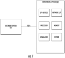
- FIG. 1 a block diagram illustrating an example electrode system 101 communicatively connected to a neuromuscular monitoring system 102 is shown.
- the electrode system 101 is communicatively connected to the monitoring system 102 through a communication link 103.
- the communication link 103 can be implemented using any medium that facilitates the exchange of signals between the electrode system 101 and the monitoring system 102.
- the electrode system 101 is the interface for delivering/detecting electrical signals to/from a subject.
- the subject or patient discussed herein can be human and non-human animals of any age.
- the electrode system 101 is discussed in detail below with regard to FIGS. 2A-4B .
- the monitoring system 102 can be a neuromuscular monitoring system, for example. It should also be understood that this disclosure contemplates that the monitoring system 102 can be any type of monitoring system including, but not limited to, a neuromuscular function testing system.
- the monitoring system 102 can include a processor and memory.
- the processor can be configured to execute program code encoded in tangible, computer-readable media.
- the processor can be configured to execute program code stored in the memory.
- Computer-readable media refers to any media capable of providing data that causes the monitoring system 102 to operate in a particular fashion.
- the computer-readable media can store program code that causes the monitoring system 102 to assess the level of neuromuscular blockade in a subject.
- Computer-readable media includes volatile and non-volatile media implemented in any method or technology for storage of information such as computer readable instructions, data structures, program modules or other data.
- the monitoring system 102 can include a stimulator configured to generate an electrical pulse.
- the stimulator can optionally be configured to generate a train of electrical pulses (e.g., train-of-four, tetanic, etc.).
- Each of the electrical pulses can be delivered to a motor nerve of the subject such as the median or ulnar nerve at the wrist, the tibial nerve at the ankle, the facial nerve beneath the ear, etc.
- Each of the electrical pulses can be of sufficient strength to elicit a nerve response.
- the stimulator can include circuitry for filtering, amplifying, and/or otherwise conditioning each of the electrical pulses.
- Each of the electrical pulses can then be delivered to the subject using the electrode system 101.
- the monitoring system 102 can include a sensor configured to detect an electrical signal from the subject.
- the sensor can be configured to detect a nerve response and/or a muscle response to each of the electrical pulses delivered to the motor nerve. Similar to the stimulator, the sensor can include circuitry for filtering, amplifying, and/or otherwise conditioning the detected electrical signals.
- the electrode system 101 can be the interface for delivering each of the electrical pulses generated and optionally conditioned by the stimulator to the subject and for receiving the raw detected electrical signals from the subject.
- the monitoring system 102 can also optionally include input/output devices and network interfaces.
- Input devices include a keyboard, touch screen, mouse, button, dial, switch, etc.
- Output devices include a display screen, speaker, printer, etc.
- Network interfaces are devices that facilitate communication between the monitoring system 102 and other devices. Input/output devices and network interfaces are well known in the art and need not be discussed at length here.
- the electrode system 101 can include a flexible substrate 10.
- the flexible substrate 10 can optionally be a polyester film substrate (e.g., MYLAR).
- the flexible substrate 10 can be any material providing the desired stiffness and/or flexibility.
- the flexible substrate 10 can be formed from a material providing sufficient stiffness to allow the medical professional to manipulate the electrode system 101 and place the electrodes on the subject.
- the flexible substrate 10 is formed from a material providing sufficient flexibility to allow the medical professional to move the electrodes relative to each other.
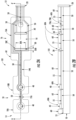
- the flexible substrate 10 can define a proximal end 12 and a distal end 14. Additionally, the flexible substrate 10 can include a first portion 16 on which one or more stimulating electrodes 30 are carried and a second portion 18 on which one or more recording electrodes 40 are carried.
- the stimulating electrodes 30 can be carried on an island 16A
- the recording electrodes 40 can be carried on islands 18A, 18B.
- Each of the stimulating electrodes 30 and the recording electrodes 40 can optionally be carried on separate islands.
- FIGS. 2A-4B show electrode systems having two stimulating electrodes and two recording electrodes, this disclosure contemplates electrode systems having more or fewer stimulating and/or recording electrodes.
- Each of the islands 16A, 18A, 18B can optionally be connected by a bridge portion 19A, 19B.
- the first portion 16 can optionally be arranged adjacent to the proximal end 12 of the flexible substrate 10, and the second portion 18 can optionally be arranged adjacent to the distal end 14 of the flexible substrate 10.
- two stimulating electrodes 30 can be arranged in a spaced apart pattern on the island 16A. Because of the flexibility of the flexible substrate 10, each of the stimulating electrodes 30 is moveable relative to the other stimulating electrodes 30. For example, the medical professional can place the stimulating electrodes 30 in the desired anatomical location such as in proximity to a motor nerve of the subject.
- the second portion 18 can optionally be an elongated portion extending distally from the first portion 16. As shown in FIGS. 2A-2B , the second portion 18 can optionally include two separate islands 18A, 18B on which each recording electrode 40 is carried. The islands 18A, 18B and corresponding recording electrodes 40 can be arranged in a spaced apart pattern.
- the islands 18A, 18B and corresponding recording electrodes 40 can be arranged approximately co-linearly.
- the second portion 18 can optionally be more flexible than the first portion 16 due to its more elongate geometry as compared to the first portion 16.
- each of the recording electrodes 40 is moveable relative to the other recording electrodes 40 and/or the one or more stimulating electrodes 30. This facilitates the medical professional in properly positioning the one or more recording electrodes 40 in the desired anatomical location.
- the medical professional can place one of the one or more recording electrodes 40 in proximity to a muscle innervated by the motor nerve and one of the one or more recording electrodes 40 at another anatomical location (e.g., spaced from the muscle innervated by the motor nerve) in order to record the muscle electrical activity in response to motor nerve stimulation as a differential signal.
- another anatomical location e.g., spaced from the muscle innervated by the motor nerve
- the electrode system 101 includes a connector interface 20 carried on the flexible substrate 10.
- the connector interface 20 can optionally be disposed at the proximal end 12 of the flexible substrate 10.
- the connector interface 20 facilitates connecting the electrode system 101 and the monitoring system (e.g., the monitoring system 102 shown in FIG. 1 ).
- the connector interface 20 communicatively connects the electrode system 101 and the monitoring system such that electrical pulses are passed from the monitoring system to the electrode system 101 for delivery to the subject via the one or more stimulating electrodes 30.
- electrical signals e.g., muscle electrical activity
- the subject are detected with the one or more recording electrodes 40 of the electrode system 101 and delivered to the monitoring system for further processing.
- the monitoring system can process the electrical signals to assess the level of neuromuscular blockade in the subject, for example.
- the electrode system 101 includes a plurality of conductive traces 50 carried on the flexible substrate 10.
- the conductive traces 50 electrically connect at least one stimulating electrode 30 or at least one recording electrode 40 with the connector interface 20. As shown in FIGS. 2A-2B , each of the one or more stimulating electrodes 30 and each of the one or more recording electrodes 40 is electrically connected to the connector interface 20 through a conductive trace 50.
- the conductive traces 50 can be a conductive pattern deposited on the flexible substrate 10 by any means known in the art including, but not limited to, screening, printing, chemical plating, etc.
- the conductive traces 50 can be formed of a conductive ink such as silver ink or a mixture of silver and carbon ink, for example.
- the silver-carbon ink creates conductive traces with lower resistance as compared to carbon ink traces at a reduced cost as compared to silver ink traces.
- the stimulating and/or recording electrodes 30, 40 can also be a conductive pattern deposited on the flexible substrate 10 by any means known in the art.
- At least a portion of the stimulating and recording electrodes 30, 40 can be formed of a conductive ink such as silver ink or a mixture of silver and carbon ink, for example.
- a conductive ink such as silver ink or a mixture of silver and carbon ink, for example.
- at least a portion of the stimulating and/or recording electrodes 30, 40 can also be formed from a mixture of silver and silver chloride ink.
- silver chloride can be provided in an approximately 20% concentration to the silver.
- the silver-silver chloride ink can be used only for a portion of each of the stimulating and/or recording electrodes 30, 40.
- the silver-silver chloride ink is more corrosive and can potentially corrode other portions of the electrode system 101 such as the connector interface 20, for example.
- the stimulating and/or recording electrodes 30, 40 can include a first layer of silver ink and/or silver-carbon ink carried on the flexible substrate 10 and a second layer of silver-silver chloride ink carried on the first layer.
- the conductive traces 50 and at least a portion of the stimulating and recording electrodes 30, 40 can be deposited on the flexible substrate 10 as a conductive ink (e.g., silver and/or silver-carbon ink) in a first step, and at least a portion of the stimulating and/or recording electrodes 30, 40 can be deposited as a conductive ink (e.g., silver-silver chloride ink) in a second step.
- a conductive ink e.g., silver and/or silver-carbon ink
- a conductive ink e.g., silver-silver chloride ink
- the electrode system 101 can include a temperature sensor 70A for measuring a temperature of the subject to which the electrode system 101 is applied.
- a temperature sensor 70A for measuring a temperature of the subject to which the electrode system 101 is applied.
- the temperature of the subject's skin effects neuromuscular testing and monitoring. For example, colder nerves have lower conduction velocities as compared to warmer nerves.
- the temperature of the subject's skin provides an indication of the temperature of the subject's nerves.
- the temperature measured by the temperature sensor 70A can be used by the monitoring system 102, for example, to notify the medical professional when the subject's skin temperature is too low to obtain accurate results, to provide temperature compensation, etc.
- the temperature sensor 70A can optionally be carried on the flexible substrate 10. Additionally, one or more of the conductive traces 50 can electrically connect the temperature sensor 70A and the connector interface 20.
- the electrode system 101 can include a security IC chip 70B configured to provide authentication between the electrode system 101 and the monitoring system(e.g., the monitoring system 102 shown in FIG. 1 ).
- the monitoring system can be configured to read or otherwise obtain a unique identifier from the security IC chip 70B.
- the unique identifier can be encoded, and the monitoring system can decode the unique identifier.
- the security IC chip 70B can be carried on the flexible substrate 10. Additionally, one or more of the conductive traces 50 can electrically connect the security IC chip 70B and the connector interface 20.
- the electrode system 101 can also include a dielectric layer 55 carried on the flexible substrate 10.
- the dielectric layer 55 provides electrical insulation.
- the dielectric layer 55 prevents shorting between any two of the plurality of conductive traces 50, the one or more stimulating electrodes 30 and the one or more recording electrodes 40.
- the dielectric layer 55 prevents inadvertent stimulation of the subject's skin through undesired conductive paths.
- the dielectric layer 55 can be provided on the flexible substrate 10 by any means known in the art.
- the dielectric layer 55 can be provided over one or more portions of the flexible substrate 10.
- the dielectric layer 55 can be provided over the flexible substrate 10 after the conductive traces 50, the one or more stimulating electrodes 30 and/or the one or more recording electrodes 40 are provided on the flexible substrate 10.
- the dielectric layer 55 can be provided over at least portions of the conductive traces 50, the one or more stimulating electrodes 30 and/or the one or more recording electrodes 40.
- the dielectric layer 55 can be provided such that areas adjacent to the one or more stimulating electrodes 30, the one or more recording electrodes 40 or the temperature sensor 70A and/or security IC chip 70B remain uncovered by the dielectric layer 55.
- the electrode system 101 can include a foam layer 60 carried on the flexible substrate 10.
- the foam layer 60 can optionally be provided on one or both sides of the flexible substrate 10.
- the electrode system 101 can include a transfer adhesive layer that binds the foam layer 60 and the flexible substrate 10.
- the foam layer 60 can define a plurality of openings 60A around each of the one or more stimulating electrodes 30, the one or more recording electrodes 40, the temperature sensor 70A and/or the security IC chip 70B.
- the foam layer 60 can be pre-cut with a plurality of openings 60A before being secured to the flexible substrate 10.
- a conductive adhesive can optionally be provided in at least one of the plurality of openings 60A such as the openings 60A around one or more of the stimulating and/or recording electrodes 30, 40.
- the plurality of openings 60A can act as wells for holding the conductive adhesive.
- the conductive adhesive can be capable of binding to the subject's skin.
- the conductive adhesive can also be capable of electrically coupling the one or more stimulating electrodes 30 and/or recording electrodes 40 to the subject's skin.
- the conductive adhesive can be a conductive adhesive gel.
- the conductive adhesive can be a conductive solid gel or a conductive liquid gel.
- the electrode system 101 can include an adhesive layer carried on the flexible substrate. The adhesive layer can be capable of binding the electrode system 101 to the subject's skin.
- Each of the one or more stimulating electrodes 30 has an elongate shape with a length dimension 30A that is substantially greater than a width dimension 30B. It is possible to minimize sensitivity to placement of the stimulating electrodes 30 when the stimulating electrodes have an elongate shape. For example, when the stimulating electrodes 30 have an elongate shape, the stimulating electrodes 30 can transect a targeted nerve more easily. In other words, the medical provider can correctly position the stimulating electrodes at the desired anatomical location such as in proximity to a motor nerve of the subject, for example, more easily when the stimulating electrodes 30 have an elongate shape.
- the length dimension 30A is substantially greater than the width dimension 30B when the length dimension 30A is at least two times greater than the width dimension 30B.
- the length dimension 30A is substantially greater than the width dimension 30B when the length dimension 30A is greater than two times the width dimension 30B.
- the length dimension 30A is substantially greater than the width dimension 30B when the length dimension 30A is at least three, four, five, six, seven or eight times greater than the width dimension 30B.
- each of the one or more stimulating electrodes 30 has a non-rectangular shape.
- each of the one or more stimulating electrodes 30 has at least one rounded corner 30C. It is possible to minimize current density, and in particular local current density peaks, by providing stimulating electrodes 30 with at least one rounded corner 30C.
- Each of the one or more stimulating electrodes 30 can optionally include first and second sides that define the length dimension 30A. The first and second sides can optionally extend substantially in parallel along the length dimension 30A.
- each of the one or more stimulating electrodes 30 can include third and fourth sides that define the width dimension 30B.
- one of the third and forth sides can be the at least one rounded corner 30C, which can connect the first and second sides.
- each of the third and forth sides can be the at least one rounded corner 30C, which connect the first and second sides at opposite ends of each of the stimulating electrodes 30.
- the at least one rounded corner can optionally connect one of the first and second side and one of the third and fourth side.
- the third and fourth sides can optionally can optionally extend substantially in parallel along the width dimension 30B, and the at least one rounded corner can optionally connect one of the first and second side and one of the third and fourth side.
- each of four corners of each of the stimulating electrodes 30 can be a rounded corner.
- each of the one or more stimulating electrodes 30 has a convex shape.
- each of the one or more stimulating electrodes 30 can have a strictly convex shape, e.g., each internal angle is less than 180 degrees.
- each of the one or more stimulating electrodes 30 has a triangular, hexagonal, octagonal, etc. shape.
- the one or more stimulating electrodes 30 having a convex shape has one or more rounded corners.
- each of the one or more stimulating electrodes 30 can have a maximum surface area less than or equal to 1.5 cm 2 .
- stimulating electrodes 30 By providing stimulating electrodes 30 with a maximum surface area less than or equal to 1.5 cm 2 , it is possible to deliver an electrical pulse with sufficient current density to the subject's skin to stimulate a nerve of the subject.
- a surface area of each of the one or more stimulating electrodes 30 can be greater than a surface area of each of the one or more recording electrodes 40.
- the surface area of each of the one or more stimulating electrodes 30 can be approximately 1.5 times greater than the surface area of each of the one or more recording electrodes 40.
- the electrode system 101 is capable of detecting the corresponding nerve and/or muscle response to a stimulated nerve as a floating differential signal with the one or more recording electrodes 40.
- the floating differential signal can be a non-ground referenced differential signal, for example.
- the electrode system 101 does not include a common ground electrode.
- the electrode system 101 is a four-electrode system.
- the electrode system 101 includes no more than four electrodes.
- the electrode system 101 can only include two recording electrodes 40 for detecting a floating differential signal and two stimulating electrodes 30 for delivering an electrical pulse.
- the method includes providing a flexible substrate 10.
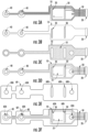
- the conductive traces 50 can be provided as a conductive pattern deposited on the flexible substrate 10 by any means known in the art including, but not limited to, screening, printing, chemical plating, etc. Additionally, at least a portion of the stimulating and/or recording electrodes 30, 40 can be provided as a conductive pattern deposited on the flexible substrate 10 by any means known in the art.
- the conductive traces 50 and at least a portion of the stimulating and/or recording electrodes 30, 40 are shaded in FIG. 3A .
- the conductive traces 50 can electrically connect at least one of the stimulating electrodes 30, the recording electrodes 40, a temperature sensor or a security IC chip with the connector interface 20.
- the conductive traces 50, stimulating electrodes and/or recording electrodes 30, 40 can be formed of a conductive ink such as silver ink or a mixture of silver and carbon ink, for example.
- at least a portion of the stimulating and/or recording electrodes 30, 40 can also be formed from a mixture of silver and silver chloride ink.
- the silver-silver chloride ink (shaded in FIG. 3B ) can be provided only over the stimulating and/or recording electrodes 30, 40.
- the stimulating and/or recording electrodes 30, 40 can include a first layer of silver ink and/or silver-carbon ink carried on the flexible substrate 10 (e.g., as shown by the shading in FIG. 3A ) and a second layer of silver-silver chloride ink carried on the first layer (e.g., as shown by shading in FIG. 3B ).
- the conductive traces 50 and at least a portion of the stimulating and/or recording electrodes 30, 40 can be deposited on the flexible substrate 10 as a conductive ink (e.g., silver and/or silver-carbon ink) in a first step, and at least a portion of the stimulating and/or recording electrodes can be deposited as a conductive ink (e.g., silver-silver chloride ink) in a second step.
- a temperature sensor and/or a security IC chip can be provided on the flexible substrate 10 as discussed above.
- a dielectric layer 55 can optionally be provided on the flexible substrate 10 by any means known in the art.
- the dielectric layer 55 is discussed in detail above.
- the dielectric layer 55 can be provided over one or more portions of the flexible substrate 10. The dielectric portion is shaded in FIG. 3C .
- the dielectric layer 55 can be provided over the flexible substrate 10 after the conductive traces 50, the one or more stimulating electrodes 30 and the one or more recording electrodes 40 are provided on the flexible substrate 10.
- the dielectric layer 55 can be provided over at least portions of the conductive traces 50, the one or more stimulating electrodes 30 or the one or more recording electrodes 40.
- the dielectric layer 55 can be provided such that areas adjacent to the one or more stimulating electrodes 30, the one or more recording electrodes 40 or the temperature sensor and/or security IC chip remain uncovered by the dielectric layer 55. This is shown in FIG. 3D .
- a foam layer 60 can be provided on the flexible substrate 10.
- the foam layer 60 is discussed in detail above.
- the foam layer 60 can optionally be provided on one or both sides of the flexible substrate 10.
- the foam layer 60 can be pre-cut with a plurality of openings 60A before being secured to the flexible substrate 10. Thereafter, the foam layer 60 can be secured to the flexible substrate 10 with a transfer adhesive, for example, as shown in FIG. 3F .
- the foam layer 60 can define a plurality of openings 60A around each of the one or more stimulating electrodes 30, the one or more recording electrodes 40, the temperature sensor and/or the security IC chip.
- the plurality of openings 60A can act as wells for holding a conductive adhesive that is capable of binding to the subject's skin and electrically coupling the one or more stimulating electrodes and/or recording electrodes 30, 40 to the subject's skin.
- FIGS. 4A-4B are front and back views illustrating the electrode system according to implementations discussed herein.
- FIG. 4A illustrates front and back views of the electrode system including the foam layer.
- FIG. 4B illustrates front and back views of the electrode system without a foam layer.
- the electrode system 101 can optionally include a flexible substrate 10, one or more stimulating electrodes 30, one or more recording electrodes 40, a plurality of conductive traces 50, a dielectric layer 55, a foam layer 60, a connector interface 20 and a temperature sensor or security IC chip 70A, 70B.
- neuromuscular monitoring can include assessing muscle electrical activity in a subject.
- This assessment can include assessing the level of neuromuscular blockade in a subject having been administered a muscle relaxant agent.
- a motor nerve can be stimulated to cause an evoked muscle response by applying a stimulus using one or more stimulating electrodes 30, and electrical activity of a muscle innervated by the motor nerve can be recorded using one or more recording electrodes 40.
- the level of neuromuscular blockade in the subject can be determined using the recorded electrical activity.
Landscapes
- Health & Medical Sciences (AREA)
- Life Sciences & Earth Sciences (AREA)
- Medical Informatics (AREA)
- Molecular Biology (AREA)
- Veterinary Medicine (AREA)
- Biophysics (AREA)
- Pathology (AREA)
- Engineering & Computer Science (AREA)
- Biomedical Technology (AREA)
- Heart & Thoracic Surgery (AREA)
- Public Health (AREA)
- Physics & Mathematics (AREA)
- Surgery (AREA)
- Animal Behavior & Ethology (AREA)
- General Health & Medical Sciences (AREA)
- Neurology (AREA)
- Neurosurgery (AREA)
- Measurement And Recording Of Electrical Phenomena And Electrical Characteristics Of The Living Body (AREA)
- Measuring And Recording Apparatus For Diagnosis (AREA)
- Electrotherapy Devices (AREA)
Priority Applications (1)
| Application Number | Priority Date | Filing Date | Title |
|---|---|---|---|
| EP23172204.2A EP4241688B1 (en) | 2013-02-15 | 2014-02-14 | Electrode systems for use with medical monitoring systems |
Applications Claiming Priority (2)
| Application Number | Priority Date | Filing Date | Title |
|---|---|---|---|
| US201361765355P | 2013-02-15 | 2013-02-15 | |
| PCT/US2014/016443 WO2014127217A1 (en) | 2013-02-15 | 2014-02-14 | Electrode systems for use with medical monitoring systems |
Related Child Applications (2)
| Application Number | Title | Priority Date | Filing Date |
|---|---|---|---|
| EP23172204.2A Division EP4241688B1 (en) | 2013-02-15 | 2014-02-14 | Electrode systems for use with medical monitoring systems |
| EP23172204.2A Division-Into EP4241688B1 (en) | 2013-02-15 | 2014-02-14 | Electrode systems for use with medical monitoring systems |
Publications (2)
| Publication Number | Publication Date |
|---|---|
| EP2956052A1 EP2956052A1 (en) | 2015-12-23 |
| EP2956052B1 true EP2956052B1 (en) | 2023-07-12 |
Family
ID=50193612
Family Applications (2)
| Application Number | Title | Priority Date | Filing Date |
|---|---|---|---|
| EP14707900.8A Active EP2956052B1 (en) | 2013-02-15 | 2014-02-14 | Electrode systems for use with medical monitoring systems |
| EP23172204.2A Active EP4241688B1 (en) | 2013-02-15 | 2014-02-14 | Electrode systems for use with medical monitoring systems |
Family Applications After (1)
| Application Number | Title | Priority Date | Filing Date |
|---|---|---|---|
| EP23172204.2A Active EP4241688B1 (en) | 2013-02-15 | 2014-02-14 | Electrode systems for use with medical monitoring systems |
Country Status (5)
| Country | Link |
|---|---|
| US (1) | US9814402B2 (enExample) |
| EP (2) | EP2956052B1 (enExample) |
| JP (1) | JP2016508400A (enExample) |
| ES (1) | ES2959159T3 (enExample) |
| WO (1) | WO2014127217A1 (enExample) |
Families Citing this family (21)
| Publication number | Priority date | Publication date | Assignee | Title |
|---|---|---|---|---|
| US9462960B2 (en) * | 2003-02-21 | 2016-10-11 | 3Dt Holdings, Llc | Impedance devices and methods of using the same to obtain luminal organ measurements |
| US10869609B2 (en) * | 2014-11-26 | 2020-12-22 | Safeop Surgical, Inc. | Device and means of assessing neuromuscular junction status with higher fidelity |
| CH710787A1 (fr) * | 2015-02-26 | 2016-08-31 | Rb Patents Sàrl | Electrode transcutanée de surface avec micropuce électronique incorporée. |
| JP2018507763A (ja) * | 2015-02-26 | 2018-03-22 | エールベ パテンツ エスアーエールエルRb Patents Sarl | 電極対を短絡し、接地するための手段を備える機能的電気刺激および筋電図測定用デバイス、ならびに関連付けされた経皮性電極 |
| CH710786A1 (fr) * | 2015-02-26 | 2016-08-31 | Rb Patents Sàrl | Système multicanaux de stimulation électrique fonctionnelle (SEF) et de mesure d'électromyogramme (EMG). |
| EP3380006B1 (en) * | 2015-11-29 | 2022-04-27 | Ramot at Tel-Aviv University Ltd. | Sensing electrode and method of fabricating the same |
| US10426371B2 (en) * | 2016-06-07 | 2019-10-01 | Smk Corporation | Muscle condition measurement sheet |
| JP6653639B2 (ja) * | 2016-06-07 | 2020-02-26 | 学校法人梅村学園 | 評価システムと評価システムに用いられる筋状態測定シート |
| EP4091661B1 (en) | 2016-10-14 | 2023-09-06 | Blink Device LLC | Quantitative neuromusculature blockade sensing systems |
| USD860465S1 (en) | 2017-11-01 | 2019-09-17 | Blink Device, Llc | Electrode array |
| US20190192051A1 (en) * | 2017-12-22 | 2019-06-27 | General Electric Company | Disposable sensor for neuromuscular transmission measurement |
| US11357981B2 (en) | 2018-03-01 | 2022-06-14 | Adventus Ventures, Llc | Systems and methods for controlling blood pressure |
| US11166648B2 (en) * | 2018-05-24 | 2021-11-09 | General Electric Company | Method and system for estimating patient recovery time utilizing neuromuscular transmission measurements |
| USD905858S1 (en) * | 2019-04-03 | 2020-12-22 | Blink Device LLC | Electrode array |
| EP4037755B1 (en) * | 2019-10-04 | 2024-07-17 | Nihon Kohden Corporation | Body electrode and body electrode unit |
| JP7520657B2 (ja) * | 2019-10-04 | 2024-07-23 | 日本光電工業株式会社 | 生体電極、及び生体電極ユニット |
| EP4041379A4 (en) * | 2019-10-11 | 2023-11-22 | Xavant Technologies (Pty) Ltd. | NON-INVASIVE DIAGNOSTIC SET AND METHOD OF USE THEREOF |
| EP3842094B1 (en) * | 2019-12-23 | 2024-05-22 | STIMVIA s.r.o. | Neuromodulation apparatus |
| USD970018S1 (en) | 2020-10-12 | 2022-11-15 | GE Precision Healthcare LLC | Sensor |
| CN115436444A (zh) * | 2021-06-01 | 2022-12-06 | 杭州暖芯迦电子科技有限公司 | 一种可抛弃式生物分子信号连续检测装置 |
| KR102769338B1 (ko) * | 2022-09-22 | 2025-02-18 | 재단법인 아산사회복지재단 | 재생 말초신경 인터페이스 및 그 제조방법 |
Citations (1)
| Publication number | Priority date | Publication date | Assignee | Title |
|---|---|---|---|---|
| US20130030277A1 (en) * | 2008-07-02 | 2013-01-31 | Fahey Brian J | Devices, Systems, and Methods for Automated Optimization of Energy Delivery |
Family Cites Families (74)
| Publication number | Priority date | Publication date | Assignee | Title |
|---|---|---|---|---|
| US3565080A (en) | 1964-12-21 | 1971-02-23 | Burroughs Wellcome Co | Neuromuscular block monitoring apparatus |
| US3364929A (en) | 1964-12-21 | 1968-01-23 | Burroughs Wellcome Co | Method for administering muscle relaxant drug |
| JPS4874685U (enExample) * | 1971-12-20 | 1973-09-17 | ||
| US3898983A (en) | 1973-10-03 | 1975-08-12 | James O Elam | Device and method for detecting the degree of muscle relaxation of a medical patient |
| US4157087A (en) | 1978-03-06 | 1979-06-05 | Med General, Inc. | Peripheral nerve stimulator |
| US4291705A (en) | 1979-09-10 | 1981-09-29 | The Regents Of The University Of California | Neuromuscular block monitor |
| US4387723A (en) | 1980-12-09 | 1983-06-14 | Wisconsin Alumni Research Foundation | Method and apparatus for determining the level of neuromuscular block in a patient |
| US4570640A (en) | 1981-08-06 | 1986-02-18 | Barsa John E | Sensory monitoring apparatus and method |
| FI73878C (fi) | 1983-06-10 | 1987-12-10 | Instrumentarium Oy | Foerfarande foer vidareutveckling av nervmuskelanslutnings maetning. |
| US4817628A (en) | 1985-10-18 | 1989-04-04 | David L. Zealear | System and method for evaluating neurological function controlling muscular movements |
| US5131401A (en) | 1990-09-10 | 1992-07-21 | Axon Medical Inc. | Method and apparatus for monitoring neuromuscular blockage |
| US5391081A (en) | 1992-05-13 | 1995-02-21 | University Of Florida Research Foundation, Incorporated | Method and apparatus for simulating neuromuscular stimulation during medical surgery |
| US5300096A (en) | 1992-06-03 | 1994-04-05 | Hall H Eugene | Electromyographic treatment device |
| US5327902A (en) | 1993-05-14 | 1994-07-12 | Lemmen Roger D | Apparatus for use in nerve conduction studies |
| JPH07222805A (ja) * | 1994-02-10 | 1995-08-22 | Japan Vilene Co Ltd | 生体用薄形電極 |
| US6233472B1 (en) * | 1995-06-06 | 2001-05-15 | Patient Comfort, L.L.C. | Electrode assembly and method for signaling a monitor |
| EP0787506A1 (en) | 1995-08-04 | 1997-08-06 | José Javier RODIERA OLIVE | Method and apparatus for monitoring and/or controlling the neuromuscular blocking, specially the blocking produced by muscular relaxing pharmaceuticals used during anaesthesia |
| US6002960A (en) | 1996-08-27 | 1999-12-14 | The Johns Hopkins University | Passive, non-invasive method to quantify objectively the level and density of a neural blockade |
| US6394953B1 (en) * | 2000-02-25 | 2002-05-28 | Aspect Medical Systems, Inc. | Electrode array system for measuring electrophysiological signals |
| US7628761B2 (en) | 1997-07-01 | 2009-12-08 | Neurometrix, Inc. | Apparatus and method for performing nerve conduction studies with localization of evoked responses |
| US6132387A (en) | 1997-07-01 | 2000-10-17 | Neurometrix, Inc. | Neuromuscular electrode |
| US6146335A (en) | 1997-07-01 | 2000-11-14 | Neurometrix, Inc. | Apparatus for methods for the assessment of neuromuscular function of the lower extremity |
| US5851191A (en) | 1997-07-01 | 1998-12-22 | Neurometrix, Inc. | Apparatus and methods for assessment of neuromuscular function |
| US6132386A (en) | 1997-07-01 | 2000-10-17 | Neurometrix, Inc. | Methods for the assessment of neuromuscular function by F-wave latency |
| JP2000000232A (ja) * | 1998-06-15 | 2000-01-07 | Toyota Central Res & Dev Lab Inc | 筋肉疲労判定装置 |
| US6076011A (en) | 1999-02-02 | 2000-06-13 | J&J Engineering | Electromyographic feedback monitor system |
| US6385473B1 (en) * | 1999-04-15 | 2002-05-07 | Nexan Limited | Physiological sensor device |
| US7470236B1 (en) | 1999-11-24 | 2008-12-30 | Nuvasive, Inc. | Electromyography system |
| JP2001190693A (ja) * | 2000-01-14 | 2001-07-17 | Nitto Denko Corp | 電極構造体 |
| AU2001269768B2 (en) | 2000-06-08 | 2005-09-01 | Nuvasive, Inc. | Relative nerve movement and status detection system and method |
| US6389312B1 (en) | 2000-07-21 | 2002-05-14 | General Electric Company | Method and system having simplified neuromuscular transmission scoring |
| US6553245B1 (en) | 2000-11-02 | 2003-04-22 | Lawrence J. Grace | Method and apparatus for self-diagnostic evaluation of nerve sensory latency |
| EP1232762A1 (en) | 2001-02-19 | 2002-08-21 | Akzo Nobel N.V. | A method and a system for administering muscle relaxant to a patient |
| US6454728B1 (en) | 2001-03-02 | 2002-09-24 | Thomas J. K. Tung | Apparatus and method for monitoring neuromuscular function |
| EP1412020B1 (en) * | 2001-05-04 | 2011-07-20 | 3M Innovative Properties Company | Corrosion prevention in biomedical electrodes |
| WO2003039353A2 (en) | 2001-11-06 | 2003-05-15 | Neurometrix, Inc. | Neuromuscular disease detection using disease specific evoked neuromuscular response analysis |
| US6643541B2 (en) | 2001-12-07 | 2003-11-04 | Motorola, Inc | Wireless electromyography sensor and system |
| US6934570B2 (en) * | 2002-01-08 | 2005-08-23 | Masimo Corporation | Physiological sensor combination |
| US6896661B2 (en) | 2002-02-22 | 2005-05-24 | Datex-Ohmeda, Inc. | Monitoring physiological parameters based on variations in a photoplethysmographic baseline signal |
| JP2003325467A (ja) * | 2002-05-13 | 2003-11-18 | Nagoya Industrial Science Research Inst | 意思伝達支援装置、及び意思伝達支援ソフトウエア |
| US6975901B2 (en) | 2002-09-06 | 2005-12-13 | The Brigham And Women's Hopital, Inc. | Anesthetic-state determing |
| CA2415173A1 (en) | 2002-12-09 | 2004-06-09 | Thomas Hemmerling | Neuromuscular monitoring using phonomyography |
| US20040122482A1 (en) | 2002-12-20 | 2004-06-24 | James Tung | Nerve proximity method and device |
| US7277759B2 (en) | 2003-02-04 | 2007-10-02 | Advanced Bionics Corporation | Method of rapid neural response measurement without amplitude attenuation |
| US7130673B2 (en) * | 2003-04-08 | 2006-10-31 | Instrumentarium Corp. | Method of positioning electrodes for central nervous system monitoring and sensing pain reactions of a patient |
| US20120046572A1 (en) | 2004-12-23 | 2012-02-23 | Ib Odderson | Nerve stimulator measuring device |
| US7499746B2 (en) | 2004-01-30 | 2009-03-03 | Encore Medical Asset Corporation | Automated adaptive muscle stimulation method and apparatus |
| US7749171B2 (en) | 2004-03-09 | 2010-07-06 | Neurometrix, Inc. | Method for automated detection of A-waves |
| WO2006009767A1 (en) * | 2004-06-18 | 2006-01-26 | Neuronetrix, Inc | Wireless electrode for biopotential measurement |
| EP1804660A4 (en) | 2004-10-07 | 2009-11-11 | Nuvasive Inc | SYSTEM AND METHOD FOR ASSESSING THE NEUROMUSCULAR PATH BEFORE NERVENTESTS |
| EP1656883A1 (fr) | 2004-11-10 | 2006-05-17 | Universite Libre De Bruxelles | Appareil de mesure portable d'un signal EMG |
| US20060111756A1 (en) | 2004-11-23 | 2006-05-25 | Chang Henry H | Method and apparatus for a neuromuscular stimulator |
| US7925338B2 (en) | 2005-03-24 | 2011-04-12 | General Electric Company | Determination of the anesthetic state of a patient |
| US20070129771A1 (en) | 2005-04-20 | 2007-06-07 | Kurtz Ronald L | Device, method and stimulus unit for testing neuromuscular function |
| JP4706962B2 (ja) | 2005-05-27 | 2011-06-22 | 日本光電工業株式会社 | 筋弛緩パラメータの表示方法および筋弛緩状態表示モニタ装置 |
| US7558610B1 (en) | 2005-06-01 | 2009-07-07 | Odderson Ib R | Electric diagnostic tape measure and method |
| US20090036792A1 (en) | 2005-09-12 | 2009-02-05 | Deluca Carlo J | Sensor system for detecting and processing EMG signals |
| US20070282217A1 (en) | 2006-06-01 | 2007-12-06 | Mcginnis William J | Methods & systems for intraoperatively monitoring nerve & muscle frequency latency and amplitude |
| CA2665121C (en) | 2006-09-16 | 2013-11-26 | Terence Gilhuly | Modeling and control for highly variable and nonlinear processes |
| US20080091090A1 (en) * | 2006-10-12 | 2008-04-17 | Kenneth Shane Guillory | Self-contained surface physiological monitor with adhesive attachment |
| US8078273B2 (en) | 2007-03-30 | 2011-12-13 | Neurometrix, Inc. | Detection and classification of neuromuscular late wave activity for the assessment of neuromuscular function |
| ES2664239T3 (es) * | 2007-09-05 | 2018-04-18 | Sensible Medical Innovations Ltd. | Método y aparato para usar radiación electromagnética para supervisar un tejido de un usuario |
| EP2197536A1 (en) | 2007-10-09 | 2010-06-23 | Imthera Medical, Inc. | System and method for neural stimulation |
| JP5020141B2 (ja) * | 2008-03-25 | 2012-09-05 | 積水化成品工業株式会社 | 粘着性ハイドロゲル、その製造用組成物及びその用途 |
| US20120083684A1 (en) | 2008-11-20 | 2012-04-05 | The Ohio State University | Digital distance measurer for nerve conduction studies |
| US9084551B2 (en) | 2008-12-08 | 2015-07-21 | Medtronic Xomed, Inc. | Method and system for monitoring a nerve |
| US20100210965A1 (en) | 2009-02-13 | 2010-08-19 | Gozani Shai N | Apparatus and method for the detection of neuromuscular signals |
| KR20120037392A (ko) | 2009-05-11 | 2012-04-19 | 티머시 테일러 데이비스 | 신경학적 모니터링 시스템 및 방법 |
| US9113802B2 (en) | 2009-07-12 | 2015-08-25 | Tomasz Andrzej Kosierkiewicz | Method of stimulating and recording from ulnar dorsal cutaneous sensory nerve |
| US9636239B2 (en) | 2009-08-20 | 2017-05-02 | Case Western Reserve University | System and method for mapping activity in peripheral nerves |
| US8457749B2 (en) | 2010-04-22 | 2013-06-04 | Medtronic, Inc. | Modulation of trigeminal reflex strength |
| CA2714857A1 (en) | 2010-09-15 | 2012-03-15 | Evan B. Friedman | Electromyographic (emg) device for the diagnosis and treatment of muscle injuries |
| US20120245482A1 (en) | 2010-09-16 | 2012-09-27 | Bolser Jeffrey W | Anesthesia Monitoring Device and Method |
| US8577440B2 (en) * | 2011-03-29 | 2013-11-05 | Covidien Lp | Method and system for positioning a sensor |
-
2014
- 2014-02-14 JP JP2015558150A patent/JP2016508400A/ja active Pending
- 2014-02-14 US US14/180,757 patent/US9814402B2/en active Active
- 2014-02-14 ES ES14707900T patent/ES2959159T3/es active Active
- 2014-02-14 WO PCT/US2014/016443 patent/WO2014127217A1/en not_active Ceased
- 2014-02-14 EP EP14707900.8A patent/EP2956052B1/en active Active
- 2014-02-14 EP EP23172204.2A patent/EP4241688B1/en active Active
Patent Citations (1)
| Publication number | Priority date | Publication date | Assignee | Title |
|---|---|---|---|---|
| US20130030277A1 (en) * | 2008-07-02 | 2013-01-31 | Fahey Brian J | Devices, Systems, and Methods for Automated Optimization of Energy Delivery |
Also Published As
| Publication number | Publication date |
|---|---|
| JP2016508400A (ja) | 2016-03-22 |
| EP2956052A1 (en) | 2015-12-23 |
| ES2959159T3 (es) | 2024-02-21 |
| US9814402B2 (en) | 2017-11-14 |
| EP4241688A3 (en) | 2023-11-22 |
| EP4241688C0 (en) | 2026-02-04 |
| US20140235991A1 (en) | 2014-08-21 |
| WO2014127217A1 (en) | 2014-08-21 |
| EP4241688B1 (en) | 2026-02-04 |
| EP4241688A2 (en) | 2023-09-13 |
Similar Documents
| Publication | Publication Date | Title |
|---|---|---|
| EP2956052B1 (en) | Electrode systems for use with medical monitoring systems | |
| US20240366109A1 (en) | Quantitative neuromusculature blockade sensing systems and methods | |
| US20130204156A1 (en) | Methods and Systems For Assessing Muscle Electrical Activity in Response to Stimulation of a Motor Nerve | |
| CN108471978A (zh) | 神经刺激设备和生物磁场测量系统 | |
| EP3797305B1 (en) | System and method for the estimation of physical parameters of a medium | |
| US11648401B2 (en) | Systems and methods for placement of spinal cord stimulator leads | |
| US20090326387A1 (en) | Electrocardiogram and Respiration Monitoring in Animals | |
| US20190192051A1 (en) | Disposable sensor for neuromuscular transmission measurement | |
| Reynaud et al. | Phrenic nerve conduction study to diagnose unilateral diaphragmatic paralysis |
Legal Events
| Date | Code | Title | Description |
|---|---|---|---|
| PUAI | Public reference made under article 153(3) epc to a published international application that has entered the european phase |
Free format text: ORIGINAL CODE: 0009012 |
|
| 17P | Request for examination filed |
Effective date: 20150915 |
|
| AK | Designated contracting states |
Kind code of ref document: A1 Designated state(s): AL AT BE BG CH CY CZ DE DK EE ES FI FR GB GR HR HU IE IS IT LI LT LU LV MC MK MT NL NO PL PT RO RS SE SI SK SM TR |
|
| AX | Request for extension of the european patent |
Extension state: BA ME |
|
| RAP1 | Party data changed (applicant data changed or rights of an application transferred) |
Owner name: ACACIA DESIGNS BV |
|
| DAX | Request for extension of the european patent (deleted) | ||
| STAA | Information on the status of an ep patent application or granted ep patent |
Free format text: STATUS: EXAMINATION IS IN PROGRESS |
|
| 17Q | First examination report despatched |
Effective date: 20200424 |
|
| REG | Reference to a national code |
Ref country code: DE Ref legal event code: R079 Free format text: PREVIOUS MAIN CLASS: A61B0005040000 Ipc: A61B0005000000 Ref country code: DE Ref legal event code: R079 Ref document number: 602014087588 Country of ref document: DE Free format text: PREVIOUS MAIN CLASS: A61B0005040000 Ipc: A61B0005000000 |
|
| GRAP | Despatch of communication of intention to grant a patent |
Free format text: ORIGINAL CODE: EPIDOSNIGR1 |
|
| STAA | Information on the status of an ep patent application or granted ep patent |
Free format text: STATUS: GRANT OF PATENT IS INTENDED |
|
| RIC1 | Information provided on ipc code assigned before grant |
Ipc: A61B 5/24 20210101ALI20220912BHEP Ipc: A61B 5/00 20060101AFI20220912BHEP |
|
| INTG | Intention to grant announced |
Effective date: 20221013 |
|
| GRAJ | Information related to disapproval of communication of intention to grant by the applicant or resumption of examination proceedings by the epo deleted |
Free format text: ORIGINAL CODE: EPIDOSDIGR1 |
|
| STAA | Information on the status of an ep patent application or granted ep patent |
Free format text: STATUS: EXAMINATION IS IN PROGRESS |
|
| GRAP | Despatch of communication of intention to grant a patent |
Free format text: ORIGINAL CODE: EPIDOSNIGR1 |
|
| STAA | Information on the status of an ep patent application or granted ep patent |
Free format text: STATUS: GRANT OF PATENT IS INTENDED |
|
| INTC | Intention to grant announced (deleted) | ||
| INTG | Intention to grant announced |
Effective date: 20230302 |
|
| RAP1 | Party data changed (applicant data changed or rights of an application transferred) |
Owner name: SENZIME AB (PUBL.) |
|
| GRAS | Grant fee paid |
Free format text: ORIGINAL CODE: EPIDOSNIGR3 |
|
| GRAA | (expected) grant |
Free format text: ORIGINAL CODE: 0009210 |
|
| STAA | Information on the status of an ep patent application or granted ep patent |
Free format text: STATUS: THE PATENT HAS BEEN GRANTED |
|
| P01 | Opt-out of the competence of the unified patent court (upc) registered |
Effective date: 20230523 |
|
| AK | Designated contracting states |
Kind code of ref document: B1 Designated state(s): AL AT BE BG CH CY CZ DE DK EE ES FI FR GB GR HR HU IE IS IT LI LT LU LV MC MK MT NL NO PL PT RO RS SE SI SK SM TR |
|
| REG | Reference to a national code |
Ref country code: CH Ref legal event code: EP |
|
| REG | Reference to a national code |
Ref country code: IE Ref legal event code: FG4D |
|
| REG | Reference to a national code |
Ref country code: DE Ref legal event code: R096 Ref document number: 602014087588 Country of ref document: DE |
|
| REG | Reference to a national code |
Ref country code: SE Ref legal event code: TRGR |
|
| REG | Reference to a national code |
Ref country code: LT Ref legal event code: MG9D |
|
| REG | Reference to a national code |
Ref country code: NL Ref legal event code: MP Effective date: 20230712 |
|
| REG | Reference to a national code |
Ref country code: AT Ref legal event code: MK05 Ref document number: 1586193 Country of ref document: AT Kind code of ref document: T Effective date: 20230712 |
|
| PG25 | Lapsed in a contracting state [announced via postgrant information from national office to epo] |
Ref country code: NL Free format text: LAPSE BECAUSE OF FAILURE TO SUBMIT A TRANSLATION OF THE DESCRIPTION OR TO PAY THE FEE WITHIN THE PRESCRIBED TIME-LIMIT Effective date: 20230712 |
|
| PG25 | Lapsed in a contracting state [announced via postgrant information from national office to epo] |
Ref country code: GR Free format text: LAPSE BECAUSE OF FAILURE TO SUBMIT A TRANSLATION OF THE DESCRIPTION OR TO PAY THE FEE WITHIN THE PRESCRIBED TIME-LIMIT Effective date: 20231013 |
|
| PG25 | Lapsed in a contracting state [announced via postgrant information from national office to epo] |
Ref country code: IS Free format text: LAPSE BECAUSE OF FAILURE TO SUBMIT A TRANSLATION OF THE DESCRIPTION OR TO PAY THE FEE WITHIN THE PRESCRIBED TIME-LIMIT Effective date: 20231112 |
|
| PG25 | Lapsed in a contracting state [announced via postgrant information from national office to epo] |
Ref country code: RS Free format text: LAPSE BECAUSE OF FAILURE TO SUBMIT A TRANSLATION OF THE DESCRIPTION OR TO PAY THE FEE WITHIN THE PRESCRIBED TIME-LIMIT Effective date: 20230712 Ref country code: PT Free format text: LAPSE BECAUSE OF FAILURE TO SUBMIT A TRANSLATION OF THE DESCRIPTION OR TO PAY THE FEE WITHIN THE PRESCRIBED TIME-LIMIT Effective date: 20231113 Ref country code: NO Free format text: LAPSE BECAUSE OF FAILURE TO SUBMIT A TRANSLATION OF THE DESCRIPTION OR TO PAY THE FEE WITHIN THE PRESCRIBED TIME-LIMIT Effective date: 20231012 Ref country code: LV Free format text: LAPSE BECAUSE OF FAILURE TO SUBMIT A TRANSLATION OF THE DESCRIPTION OR TO PAY THE FEE WITHIN THE PRESCRIBED TIME-LIMIT Effective date: 20230712 Ref country code: LT Free format text: LAPSE BECAUSE OF FAILURE TO SUBMIT A TRANSLATION OF THE DESCRIPTION OR TO PAY THE FEE WITHIN THE PRESCRIBED TIME-LIMIT Effective date: 20230712 Ref country code: IS Free format text: LAPSE BECAUSE OF FAILURE TO SUBMIT A TRANSLATION OF THE DESCRIPTION OR TO PAY THE FEE WITHIN THE PRESCRIBED TIME-LIMIT Effective date: 20231112 Ref country code: HR Free format text: LAPSE BECAUSE OF FAILURE TO SUBMIT A TRANSLATION OF THE DESCRIPTION OR TO PAY THE FEE WITHIN THE PRESCRIBED TIME-LIMIT Effective date: 20230712 Ref country code: GR Free format text: LAPSE BECAUSE OF FAILURE TO SUBMIT A TRANSLATION OF THE DESCRIPTION OR TO PAY THE FEE WITHIN THE PRESCRIBED TIME-LIMIT Effective date: 20231013 Ref country code: FI Free format text: LAPSE BECAUSE OF FAILURE TO SUBMIT A TRANSLATION OF THE DESCRIPTION OR TO PAY THE FEE WITHIN THE PRESCRIBED TIME-LIMIT Effective date: 20230712 Ref country code: AT Free format text: LAPSE BECAUSE OF FAILURE TO SUBMIT A TRANSLATION OF THE DESCRIPTION OR TO PAY THE FEE WITHIN THE PRESCRIBED TIME-LIMIT Effective date: 20230712 |
|
| REG | Reference to a national code |
Ref country code: ES Ref legal event code: FG2A Ref document number: 2959159 Country of ref document: ES Kind code of ref document: T3 Effective date: 20240221 |
|
| PG25 | Lapsed in a contracting state [announced via postgrant information from national office to epo] |
Ref country code: PL Free format text: LAPSE BECAUSE OF FAILURE TO SUBMIT A TRANSLATION OF THE DESCRIPTION OR TO PAY THE FEE WITHIN THE PRESCRIBED TIME-LIMIT Effective date: 20230712 |
|
| REG | Reference to a national code |
Ref country code: DE Ref legal event code: R097 Ref document number: 602014087588 Country of ref document: DE |
|
| PG25 | Lapsed in a contracting state [announced via postgrant information from national office to epo] |
Ref country code: SM Free format text: LAPSE BECAUSE OF FAILURE TO SUBMIT A TRANSLATION OF THE DESCRIPTION OR TO PAY THE FEE WITHIN THE PRESCRIBED TIME-LIMIT Effective date: 20230712 Ref country code: RO Free format text: LAPSE BECAUSE OF FAILURE TO SUBMIT A TRANSLATION OF THE DESCRIPTION OR TO PAY THE FEE WITHIN THE PRESCRIBED TIME-LIMIT Effective date: 20230712 Ref country code: EE Free format text: LAPSE BECAUSE OF FAILURE TO SUBMIT A TRANSLATION OF THE DESCRIPTION OR TO PAY THE FEE WITHIN THE PRESCRIBED TIME-LIMIT Effective date: 20230712 Ref country code: DK Free format text: LAPSE BECAUSE OF FAILURE TO SUBMIT A TRANSLATION OF THE DESCRIPTION OR TO PAY THE FEE WITHIN THE PRESCRIBED TIME-LIMIT Effective date: 20230712 Ref country code: CZ Free format text: LAPSE BECAUSE OF FAILURE TO SUBMIT A TRANSLATION OF THE DESCRIPTION OR TO PAY THE FEE WITHIN THE PRESCRIBED TIME-LIMIT Effective date: 20230712 Ref country code: SK Free format text: LAPSE BECAUSE OF FAILURE TO SUBMIT A TRANSLATION OF THE DESCRIPTION OR TO PAY THE FEE WITHIN THE PRESCRIBED TIME-LIMIT Effective date: 20230712 |
|
| PLBE | No opposition filed within time limit |
Free format text: ORIGINAL CODE: 0009261 |
|
| STAA | Information on the status of an ep patent application or granted ep patent |
Free format text: STATUS: NO OPPOSITION FILED WITHIN TIME LIMIT |
|
| PG25 | Lapsed in a contracting state [announced via postgrant information from national office to epo] |
Ref country code: IT Free format text: LAPSE BECAUSE OF FAILURE TO SUBMIT A TRANSLATION OF THE DESCRIPTION OR TO PAY THE FEE WITHIN THE PRESCRIBED TIME-LIMIT Effective date: 20230712 |
|
| 26N | No opposition filed |
Effective date: 20240415 |
|
| PG25 | Lapsed in a contracting state [announced via postgrant information from national office to epo] |
Ref country code: SI Free format text: LAPSE BECAUSE OF FAILURE TO SUBMIT A TRANSLATION OF THE DESCRIPTION OR TO PAY THE FEE WITHIN THE PRESCRIBED TIME-LIMIT Effective date: 20230712 |
|
| PG25 | Lapsed in a contracting state [announced via postgrant information from national office to epo] |
Ref country code: MC Free format text: LAPSE BECAUSE OF FAILURE TO SUBMIT A TRANSLATION OF THE DESCRIPTION OR TO PAY THE FEE WITHIN THE PRESCRIBED TIME-LIMIT Effective date: 20230712 |
|
| PG25 | Lapsed in a contracting state [announced via postgrant information from national office to epo] |
Ref country code: LU Free format text: LAPSE BECAUSE OF NON-PAYMENT OF DUE FEES Effective date: 20240214 |
|
| PG25 | Lapsed in a contracting state [announced via postgrant information from national office to epo] |
Ref country code: LU Free format text: LAPSE BECAUSE OF NON-PAYMENT OF DUE FEES Effective date: 20240214 |
|
| PG25 | Lapsed in a contracting state [announced via postgrant information from national office to epo] |
Ref country code: BG Free format text: LAPSE BECAUSE OF FAILURE TO SUBMIT A TRANSLATION OF THE DESCRIPTION OR TO PAY THE FEE WITHIN THE PRESCRIBED TIME-LIMIT Effective date: 20230712 |
|
| PG25 | Lapsed in a contracting state [announced via postgrant information from national office to epo] |
Ref country code: BG Free format text: LAPSE BECAUSE OF FAILURE TO SUBMIT A TRANSLATION OF THE DESCRIPTION OR TO PAY THE FEE WITHIN THE PRESCRIBED TIME-LIMIT Effective date: 20230712 |
|
| REG | Reference to a national code |
Ref country code: BE Ref legal event code: MM Effective date: 20240229 |
|
| PG25 | Lapsed in a contracting state [announced via postgrant information from national office to epo] |
Ref country code: BE Free format text: LAPSE BECAUSE OF NON-PAYMENT OF DUE FEES Effective date: 20240229 |
|
| PG25 | Lapsed in a contracting state [announced via postgrant information from national office to epo] |
Ref country code: IE Free format text: LAPSE BECAUSE OF NON-PAYMENT OF DUE FEES Effective date: 20240214 |
|
| PG25 | Lapsed in a contracting state [announced via postgrant information from national office to epo] |
Ref country code: IE Free format text: LAPSE BECAUSE OF NON-PAYMENT OF DUE FEES Effective date: 20240214 Ref country code: BE Free format text: LAPSE BECAUSE OF NON-PAYMENT OF DUE FEES Effective date: 20240229 |
|
| PG25 | Lapsed in a contracting state [announced via postgrant information from national office to epo] |
Ref country code: CY Free format text: LAPSE BECAUSE OF FAILURE TO SUBMIT A TRANSLATION OF THE DESCRIPTION OR TO PAY THE FEE WITHIN THE PRESCRIBED TIME-LIMIT; INVALID AB INITIO Effective date: 20140214 |
|
| PG25 | Lapsed in a contracting state [announced via postgrant information from national office to epo] |
Ref country code: HU Free format text: LAPSE BECAUSE OF FAILURE TO SUBMIT A TRANSLATION OF THE DESCRIPTION OR TO PAY THE FEE WITHIN THE PRESCRIBED TIME-LIMIT; INVALID AB INITIO Effective date: 20140214 |
|
| PG25 | Lapsed in a contracting state [announced via postgrant information from national office to epo] |
Ref country code: TR Free format text: LAPSE BECAUSE OF FAILURE TO SUBMIT A TRANSLATION OF THE DESCRIPTION OR TO PAY THE FEE WITHIN THE PRESCRIBED TIME-LIMIT Effective date: 20230712 |
|
| REG | Reference to a national code |
Ref country code: CH Ref legal event code: U11 Free format text: ST27 STATUS EVENT CODE: U-0-0-U10-U11 (AS PROVIDED BY THE NATIONAL OFFICE) Effective date: 20260301 |
|
| PGFP | Annual fee paid to national office [announced via postgrant information from national office to epo] |
Ref country code: SE Payment date: 20260219 Year of fee payment: 13 |
|
| PGFP | Annual fee paid to national office [announced via postgrant information from national office to epo] |
Ref country code: GB Payment date: 20260217 Year of fee payment: 13 |
|
| PGFP | Annual fee paid to national office [announced via postgrant information from national office to epo] |
Ref country code: ES Payment date: 20260303 Year of fee payment: 13 |
|
| PGFP | Annual fee paid to national office [announced via postgrant information from national office to epo] |
Ref country code: DE Payment date: 20260217 Year of fee payment: 13 |
|
| PGFP | Annual fee paid to national office [announced via postgrant information from national office to epo] |
Ref country code: FR Payment date: 20260217 Year of fee payment: 13 |
|
| PGFP | Annual fee paid to national office [announced via postgrant information from national office to epo] |
Ref country code: CH Payment date: 20260301 Year of fee payment: 13 |