EP2956047B1 - Iris expander - Google Patents
Iris expander Download PDFInfo
- Publication number
- EP2956047B1 EP2956047B1 EP14762382.1A EP14762382A EP2956047B1 EP 2956047 B1 EP2956047 B1 EP 2956047B1 EP 14762382 A EP14762382 A EP 14762382A EP 2956047 B1 EP2956047 B1 EP 2956047B1
- Authority
- EP
- European Patent Office
- Prior art keywords
- iris
- segments
- state
- expander
- iris expander
- Prior art date
- Legal status (The legal status is an assumption and is not a legal conclusion. Google has not performed a legal analysis and makes no representation as to the accuracy of the status listed.)
- Active
Links
Images


Classifications
-
- A—HUMAN NECESSITIES
- A61—MEDICAL OR VETERINARY SCIENCE; HYGIENE
- A61B—DIAGNOSIS; SURGERY; IDENTIFICATION
- A61B17/00—Surgical instruments, devices or methods, e.g. tourniquets
- A61B17/02—Surgical instruments, devices or methods, e.g. tourniquets for holding wounds open; Tractors
- A61B17/0231—Surgical instruments, devices or methods, e.g. tourniquets for holding wounds open; Tractors for eye surgery
-
- A—HUMAN NECESSITIES
- A61—MEDICAL OR VETERINARY SCIENCE; HYGIENE
- A61F—FILTERS IMPLANTABLE INTO BLOOD VESSELS; PROSTHESES; DEVICES PROVIDING PATENCY TO, OR PREVENTING COLLAPSING OF, TUBULAR STRUCTURES OF THE BODY, e.g. STENTS; ORTHOPAEDIC, NURSING OR CONTRACEPTIVE DEVICES; FOMENTATION; TREATMENT OR PROTECTION OF EYES OR EARS; BANDAGES, DRESSINGS OR ABSORBENT PADS; FIRST-AID KITS
- A61F9/00—Methods or devices for treatment of the eyes; Devices for putting-in contact lenses; Devices to correct squinting; Apparatus to guide the blind; Protective devices for the eyes, carried on the body or in the hand
- A61F9/007—Methods or devices for eye surgery
-
- A—HUMAN NECESSITIES
- A61—MEDICAL OR VETERINARY SCIENCE; HYGIENE
- A61B—DIAGNOSIS; SURGERY; IDENTIFICATION
- A61B17/00—Surgical instruments, devices or methods, e.g. tourniquets
- A61B17/02—Surgical instruments, devices or methods, e.g. tourniquets for holding wounds open; Tractors
- A61B17/0293—Surgical instruments, devices or methods, e.g. tourniquets for holding wounds open; Tractors with ring member to support retractor elements
-
- A—HUMAN NECESSITIES
- A61—MEDICAL OR VETERINARY SCIENCE; HYGIENE
- A61F—FILTERS IMPLANTABLE INTO BLOOD VESSELS; PROSTHESES; DEVICES PROVIDING PATENCY TO, OR PREVENTING COLLAPSING OF, TUBULAR STRUCTURES OF THE BODY, e.g. STENTS; ORTHOPAEDIC, NURSING OR CONTRACEPTIVE DEVICES; FOMENTATION; TREATMENT OR PROTECTION OF EYES OR EARS; BANDAGES, DRESSINGS OR ABSORBENT PADS; FIRST-AID KITS
- A61F9/00—Methods or devices for treatment of the eyes; Devices for putting-in contact lenses; Devices to correct squinting; Apparatus to guide the blind; Protective devices for the eyes, carried on the body or in the hand
- A61F9/007—Methods or devices for eye surgery
- A61F9/00736—Instruments for removal of intra-ocular material or intra-ocular injection, e.g. cataract instruments
-
- A—HUMAN NECESSITIES
- A61—MEDICAL OR VETERINARY SCIENCE; HYGIENE
- A61B—DIAGNOSIS; SURGERY; IDENTIFICATION
- A61B17/00—Surgical instruments, devices or methods, e.g. tourniquets
- A61B2017/00681—Aspects not otherwise provided for
-
- A—HUMAN NECESSITIES
- A61—MEDICAL OR VETERINARY SCIENCE; HYGIENE
- A61B—DIAGNOSIS; SURGERY; IDENTIFICATION
- A61B17/00—Surgical instruments, devices or methods, e.g. tourniquets
- A61B2017/00831—Material properties
- A61B2017/00862—Material properties elastic or resilient
-
- A—HUMAN NECESSITIES
- A61—MEDICAL OR VETERINARY SCIENCE; HYGIENE
- A61B—DIAGNOSIS; SURGERY; IDENTIFICATION
- A61B17/00—Surgical instruments, devices or methods, e.g. tourniquets
- A61B2017/00831—Material properties
- A61B2017/00867—Material properties shape memory effect
- A61B2017/00871—Material properties shape memory effect polymeric
-
- A—HUMAN NECESSITIES
- A61—MEDICAL OR VETERINARY SCIENCE; HYGIENE
- A61B—DIAGNOSIS; SURGERY; IDENTIFICATION
- A61B17/00—Surgical instruments, devices or methods, e.g. tourniquets
- A61B2017/00831—Material properties
- A61B2017/00955—Material properties thermoplastic
Definitions
- a surgeon In order to minimize intra- and post-operative complications from cataract extraction, a surgeon must have the best possible view of intraocular tissue. There may be occasion when a small pupil is encountered, such as with pseudoexfoliation, posterior synechiae, use of miotics, or, uveitis.
- a pupil cannot be properly dilated for cataract extraction, there is risk of: iris damage; incomplete aspiration of lens fragments and cortical material; damage to the posterior capsule; compromised capsulorhexis; loss of vitreous; and, dropped nucleus into the vitreous cavity.
- IFIS intraoperative floppy iris syndrome
- Treatments prior to cataract extraction may include: a pharmacological approach (NSAID's, preservative-free epinephrine, viscoelastic substances); mechanical manipulation (iris hooks/retractors, iris rings/dilators); and, iris surgery.
- NSAID's pharmacological approach
- epinephrine preservative-free epinephrine
- viscoelastic substances e.g., viscoelastic substances
- mechanical manipulation iris hooks/retractors, iris rings/dilators
- WO 2013/059305 A1 published after the priority date of the present invention, describes a structure for dilating a pupil during an ophthalmic procedure, comprising a ring, the ring being closed upon itself and not having free ends, and having an inner periphery and an outer periphery, a series of spaced supports for engaging an iris perimeter, the supports being elements with an open pocket directed outwardly for engaging the iris, each pocket formed by two plates, the plates being spaced apart to form the opening of each pocket, and the open pocket extending as an unimpeded space from the outer periphery through to the inner periphery of the ring.
- US 6 068 643 A describes a device for dilating a pupil and/or maintaining a pupil in a dilated state.
- the device includes a generally arcuate body having first and second ends.
- the outer peripheral edge of the body has an engaging formation adapted to engage the inner peripheral edge of an iris to retain the pupil in an expanded state, and at least one positioning arm extending generally outwardly from one of the ends of the body so as to remain external to the eye.
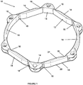
- an iris expander 10 which includes a body 12 which is expandable from a first, collapsed state to a second, expanded state.
- the body 12 defines a larger footprint in the second state than in the first state.
- the expansion of the body 12 allows for introduction of the iris expander 10 in a low profile state and expansion in situ to expand an iris for an ophthalmic procedure, such as cataract extraction, and maintenance of that expanded state for the duration of the procedure. After the procedure, the iris expander 10 may be collapsed and removed.
- the body 12 is multi-segmented and defined by a plurality of segments 14 connected by living hinges 16.
- the body 12 may be unitarily formed from non-metallic materials, such as polymeric materials, including, but not limited to, thermoplastics, elastomers and combinations thereof (e.g., copolymers of thermoplastics/elastomers).
- the body 12 needs to be biocompatible and sterilizable.
- the living hinges 16 the segments 14 are pivotable relative to each other to permit the body 12 to be initially prepared in the first state and then expanded to the second state.
- the living hinges 16 provide pivot points and/or points of relief to facilitate resilient deformation of the segments 14 when in the first state.
- the living hinges 16 may be formed by thinned sections of the body 12 so as to define isthmuses between adjacent pairs of the segments 14.
- the living hinges 16 may be formed with initial forming (e.g., molding) of the body 12 so as to have thin flexible profiles and/or may be prepared by secondary manufacturing processes which allow for material removal (e.g., cutting) to define the thinned sections.
- the living hinges 16 are sufficiently flexible to permit reversible bending thereof in allowing for angular rotation between two adjacent segments 14 about the joining living hinge 16.
- the body 12 may be adapted to be manually expandable (e.g., where the body 12 is formed of thermoplastic material (e.g., polypropylene)) or to be self-expanding (e.g., where the body 12 is formed of elastomeric or thermoplastic/elastomeric material (e.g., elastomeric polyurethane)).
- the living hinges 16 need not be provided with any inherent memory or other bias for expansion of the body 12. Rather, as described below, manual force may be applied to the body 12 to achieve expansion.
- the living hinges 16 may be formed sufficiently rigid so as to remain in a state once urged into such position (e.g., remain in particular states with the body 12 in the second expanded state). This allows for the body 12 to remain in a fixed state, such as the second state.
- the living hinges 16 may include inherent memory so as to have an internal bias towards the expanded, second state. Such memory may generate a force urging the living hinges 16 towards the expanded state. This force will also act on the segments 14. Sufficient force must be generated to not only cause expansion of the body 12 but also overcome any resistive force of the iris in causing expansion thereof. Also, the inherent memory will impart a force to the living hinges 16 to maintain the living hinges 16 in the expanded state.
- the body 12 is initially formed in the second, expanded state where self-expanding is desired.
- the body 12 is formed as a closed loop which is intended to engage the margin of the iris with at least portions of, preferably the entirety of, its outer perimeter when in the expanded state.
- the body 12 can be of various shapes, including being elliptical (e.g., circular) or polygonal (e.g., square).
- the segments 14 and the living hinges 16 extend continuously about the length of the body 12 without any interruptions so as to prevent any portion of the iris to extend through the body 12.
- the body is generally planar with expansion from the first state to the second state occurring in a single expansion plane.
- the footprint of the body 12 in the second state as defined by outer side surface 29 of the body 12 ( Figures 4 , 4A, 4B ), define a diameter of at least 6 mm, more preferably at least 7 mm.
- the segments 14 can be provided in various lengths and shapes to provide desired first and second states of the body 12.
- the body 12 in the second state may have a generally circular shape.
- eight of the living hinges 16 may be provided which separates the body 12 into eight of the segments 14, the segments 14 not being of equal length.
- primary segments 14A are each provided with an arcuate shape with the primary segments 14A being positioned to bow outwardly from each other with the body 12 being in the first state.
- the remaining segments 14 are configured to be located within the primary segments 14A with the body 12 being in the first state.
- four secondary segments 14B may be provided each of generally the same length with one of the secondary segments 14B extending from each end of the primary segments 14A.
- Two tertiary segments 14C are provided which each connect a pair of the secondary segments 14B.
- the secondary segments 14B and the tertiary segments 14C may be folded and maintained inside of the primary segments 14A as shown.
- Lobes 18 formed on the body 12 should be configured to minimally inhibit, if not avoid altogether inhibiting, full collapsing of the body 12, particularly where the lobes 18 are located interiorly of at least some of the segments 14 with the body 12 in first state.
- the lobes 18 formed on the tertiary segments 14C should be shaped to not inhibit full collapsing of the secondary segments 14B inside of the primary segments 14A.
- the body 12 may be formed with the segments 14 being of equal lengths.
- Figures 4-10 show the body 12 having eight of the living hinges 16 which separates the body 12 into eight of the segments 14.
- the body 12 may be formed with four of the living hinges 16 separating the body 12 into four of the segments 14.
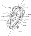
- Figure 2 provides a first state which is expandable outwardly along two Cartesian axes (represented in Figure 2 by "X” and “Y” arrows).
- Figures 7-10 , 11-13 and 14-16 each show the body 12 in a first state which is expandable outwardly along one Cartesian axis (represented in Figure 7 by "X” arrows).
- the body 12 is collapsed about two of the living hinges 16, which may be opposing, to define first and second ends 32, 34.
- the lobes 18 are located exteriorly of all of the segments 14.
- the body 12 may foreshorten along the perpendicular Cartesian axis during expansion (represented in Figure 7 by "Y" arrows) with this configuration.
- Living hinges 16 may be located at various mid-points between the first and second ends 32, 34 depending on the lengths of the corresponding segments 14. Where the segments 14 are of equal length, the living hinges 16 will be located generally centrally between the first and second ends 32, 34.
- the living hinges 16 not located at the ends 32, 34 may act as points of relief to facilitate resilient deformation of the segments 14 in the first state. This allows for the segments 14 to have natural at-rest arcuate shapes in the second state, yet be deformed to generally straight shapes with the body 12 in the first state. The release of the segments 14 from the deformed straight states to their natural at-rest states may impart force of expansion to the body 12 where self-expansion thereof is desired.
- One or more of the lobes 18 may be provided on the body 12 for extending over a portion of the iris during implantation and/or expansion of the iris expander 10.
- a plurality of the lobes 18 may be spaced about the body 12 at equal intervals along a single edge of the body 12, such as first edge 24 of the body 12.
- the lobes 18 are positioned so that a portion of the iris is received adjacent thereto. This provides a locating function for the iris expander 10 relative to the iris and additional stability in while expanding the body 12 and holding the body 12 in the expanded state.
- the lobes 18 may be provided along both the first edge 24 and second edge 26 of the body 12.
- the lobes 18 on the first and second edges 24, 26 may be aligned about the perimeter of the body 12 so as to form U-shaped pockets 28 directly between a pair of the lobes 18 located above and below.
- the pockets 28 may receive portions of the iris.
- the lobes 18 may be spaced in equal intervals about each of the first edge 24 and the second edge 26 but out of phase between the first and second edges 24, 26 so that the lobes 18 alternately protrude from the opposing edges 24, 26 about the body 12. This arrangement provides upper and lower stabilization without defining the pockets 28.
- the lobes 18 may be formed solidly ( Figure 3 ) so as to be continuous or frame shaped ( Figure 14 ) with portions thereof being open. In addition, the lobes 18 may be located centrally ( Figure 4 ) or off-center ( Figure 17 ) on the segments 14. This allows for different positions of the lobes 18 with the body 12 in the first state, as shown in comparing Figures 14-16 and Figure 20 .
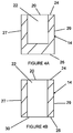
- one or more of the lobes 18 may include an aperture 20 from which extends a channel 22.
- the channel 22 is formed to accommodate a portion of an instrument for positioning the body 12 and/or causing expansion of the body 12.
- the channel 22 may be blind or may extend through the respective lobe 18 to a second aperture 30 so as to be exposed externally of the adjacent segment 14. If the lobes 18 are frame shaped, the instrument may be inserted into an open portion thereof.
- the channel 22 is located to extend through one of the segments 14 with the aperture 20 being exposed on the first edge 24 of the body 12 along the corresponding segment 14. In this manner, the channel 22 is embedded in the segment 14 with no portion thereof exposed externally of the body 12, as shown schematically in Figures 4A and 4B .
- the channel 22 is completely spaced inwardly from both inner side surface 27 and the outer side surface 29 of the body 12. This arrangement locates an instrument received in the channel 22 out of axial alignment with the iris tissue.
- the channel 22 may be blind ( Figure 4A ) or may extend to the second aperture 30 ( Figure 4B ) which is exposed externally on the second edge 26.
- an instrument engaged in the channel 22 is located inwardly of the margin of the iris.
- the channel 22 extends along a longitudinal axis which is transverse to the expansion plane.
- a plurality of the channels 22 may be provided in the body 12, each with a corresponding aperture 20.
- the channel 22 may be evenly spaced about the body 12.
- one of the lobes 18 may be located adjacent to each of the channels 22. This allows for additional tissue stabilization at potential locations of force application for expansion.
- the placement of the channel 22 wholly within the body 12 may be utilized with various configurations of the body 12 as described above with respect to the first embodiment.
- the body 12 can be multi-segmented with a plurality of the segments 14.
- the living hinges 16 are not required for the second embodiment of the invention; various hinges, and other connections, between the segments 14 may be utilized.
- the second embodiment may be practiced in the same manner as the first embodiment.
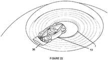
- a corneal incision 36 is initially made in a patient's eye to be treated.
- a typical corneal incision for cataract extraction may be utilized.
- the iris expander 10 is introduced into the eye with the body 12 being in the first, collapsed state.
- forceps F or other instruments may be used to insert the iris expander 10 through the corneal incision 36 and locate the iris expander 10 within the iris I.
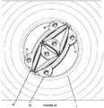
- the iris expander 10 is positioned so that the iris margin is aligned with at least a portion of the lobes 18 ( Figure 23 ).
- One or more instruments such as hooks H (e.g., Sinskey hooks), may be used to properly position the iris expander 10 ( Figure 24 ). Secondary incisions 38 in the cornea may be utilized as needed.
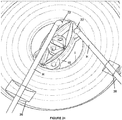
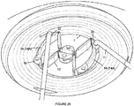
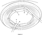
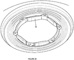
- the iris expander 10 is manually expanded by applying force in generally opposing directions. As shown here, certain segments 14, such as the primary segments 14A, may be first extended outwardly. This partial expansion of the iris expander 10 allows for partial expansion of the iris I. Thereafter, remaining portions of the body 12 may be expanded, such as shown in Figure 26 . This continues until full expansion of the iris expander 10 is achieved. Once fully expanded ( Figure 28 ), an ophthalmic procedure may be conducted. After the procedure, the iris expander 10 is collapsed and removed using a reverse procedure.
- hooks H e.g., Sinskey hooks
- the iris expander 10 may be maintained in the first state by an introducer C inserted through the corneal incision 36 ( Figure 29 ).
- the introducer C e.g., a pusher plunger instrument
- the iris expander 10 expands to the second state.
- An instrument such as one or more hooks (e.g., Sinskey hooks), may be used to adjust the position of the iris expander 10 as necessary.
- an ophthalmic procedure may be conducted. After the procedure, the iris expander 10 is collapsed, e.g., by retraction into the introducer C.
Description
- In order to minimize intra- and post-operative complications from cataract extraction, a surgeon must have the best possible view of intraocular tissue. There may be occasion when a small pupil is encountered, such as with pseudoexfoliation, posterior synechiae, use of miotics, or, uveitis.
- If a pupil cannot be properly dilated for cataract extraction, there is risk of: iris damage; incomplete aspiration of lens fragments and cortical material; damage to the posterior capsule; compromised capsulorhexis; loss of vitreous; and, dropped nucleus into the vitreous cavity.
- A rise in the incidence of intraoperative floppy iris syndrome, or IFIS, has been noted. Cited results from a retrospective and prospective study indicate that IFIS is encountered approximately 2% of the time. (Chang, D.F., Campbell J.R., "Intraoperative Floppy Iris Syndrome Associated With Tamsulosin", J. Cataract Refract. Surg. 2005; 31: 664-673). Most of the affected patients were found to be taking alpha 1 blockers, such as tamsulosin ("Flomax"), to address benign prostatic hyperplasia. Alpha 1 blockers may cause the iris dilator muscle to relax which makes pupil dilation difficult.
- Treatments prior to cataract extraction may include: a pharmacological approach (NSAID's, preservative-free epinephrine, viscoelastic substances); mechanical manipulation (iris hooks/retractors, iris rings/dilators); and, iris surgery.
-
WO 2013/059305 A1 , published after the priority date of the present invention, describes a structure for dilating a pupil during an ophthalmic procedure, comprising a ring, the ring being closed upon itself and not having free ends, and having an inner periphery and an outer periphery, a series of spaced supports for engaging an iris perimeter, the supports being elements with an open pocket directed outwardly for engaging the iris, each pocket formed by two plates, the plates being spaced apart to form the opening of each pocket, and the open pocket extending as an unimpeded space from the outer periphery through to the inner periphery of the ring. -
US 6 068 643 A describes a device for dilating a pupil and/or maintaining a pupil in a dilated state. The device includes a generally arcuate body having first and second ends. The outer peripheral edge of the body has an engaging formation adapted to engage the inner peripheral edge of an iris to retain the pupil in an expanded state, and at least one positioning arm extending generally outwardly from one of the ends of the body so as to remain external to the eye. - The present invention is defined in claim 1. Advantageous features are recited in the dependent claims.
- These and other features of the invention will be better understood through a study of the following detailed description and accompanying drawings.
-
-
Figure 1 shows an iris expander formed in accordance with the disclosure; -
Figure 2 shows the iris expander ofFigure 1 in a collapsed state; -
Figure 3 shows lobes useable with the disclosure; -
Figures 4-6 are different views of a further iris expander formed in accordance with the disclosure; -
Figures 4A and 4B show different channel configurations useable with the disclosure; -
Figures 7-10 are different views of the iris expander ofFigures 4-6 in a collapsed state; -
Figures 11-13 are different views of a further iris expander formed in accordance with the disclosure; -
Figures 14-16 are different views of an iris expander similar to the iris expander ofFigures 11-13 , but with frame-shaped lobes, in a collapsed state; -
Figures 17-19 are different views of a further iris expander formed in accordance with the disclosure; -
Figure 20 shows the iris expander ofFigures 17-19 in a collapsed state; and, -
Figures 21-29 show various aspects of introducing and using an iris expander formed in accordance with the disclosure. - With reference to the Figures, an
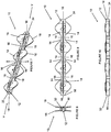
iris expander 10 is provided which includes abody 12 which is expandable from a first, collapsed state to a second, expanded state. Thebody 12 defines a larger footprint in the second state than in the first state. The expansion of thebody 12 allows for introduction of the iris expander 10 in a low profile state and expansion in situ to expand an iris for an ophthalmic procedure, such as cataract extraction, and maintenance of that expanded state for the duration of the procedure. After the procedure, the iris expander 10 may be collapsed and removed. - In a first embodiment, the
body 12 is multi-segmented and defined by a plurality ofsegments 14 connected byliving hinges 16. With this arrangement, thebody 12 may be unitarily formed from non-metallic materials, such as polymeric materials, including, but not limited to, thermoplastics, elastomers and combinations thereof (e.g., copolymers of thermoplastics/elastomers). Thebody 12 needs to be biocompatible and sterilizable. With theliving hinges 16, thesegments 14 are pivotable relative to each other to permit thebody 12 to be initially prepared in the first state and then expanded to the second state. Theliving hinges 16 provide pivot points and/or points of relief to facilitate resilient deformation of thesegments 14 when in the first state. - The
living hinges 16 may be formed by thinned sections of thebody 12 so as to define isthmuses between adjacent pairs of thesegments 14. Theliving hinges 16 may be formed with initial forming (e.g., molding) of thebody 12 so as to have thin flexible profiles and/or may be prepared by secondary manufacturing processes which allow for material removal (e.g., cutting) to define the thinned sections. Theliving hinges 16 are sufficiently flexible to permit reversible bending thereof in allowing for angular rotation between twoadjacent segments 14 about the joiningliving hinge 16. - Based on material selection and/or manufacturing technique for the
body 12, thebody 12 may be adapted to be manually expandable (e.g., where thebody 12 is formed of thermoplastic material (e.g., polypropylene)) or to be self-expanding (e.g., where thebody 12 is formed of elastomeric or thermoplastic/elastomeric material (e.g., elastomeric polyurethane)). Where thebody 12 is adapted to be manually expandable, theliving hinges 16 need not be provided with any inherent memory or other bias for expansion of thebody 12. Rather, as described below, manual force may be applied to thebody 12 to achieve expansion. Theliving hinges 16 may be formed sufficiently rigid so as to remain in a state once urged into such position (e.g., remain in particular states with thebody 12 in the second expanded state). This allows for thebody 12 to remain in a fixed state, such as the second state. Alternatively, where thebody 12 is adapted to be self-expanding, theliving hinges 16 may include inherent memory so as to have an internal bias towards the expanded, second state. Such memory may generate a force urging theliving hinges 16 towards the expanded state. This force will also act on thesegments 14. Sufficient force must be generated to not only cause expansion of thebody 12 but also overcome any resistive force of the iris in causing expansion thereof. Also, the inherent memory will impart a force to theliving hinges 16 to maintain theliving hinges 16 in the expanded state. Preferably, thebody 12 is initially formed in the second, expanded state where self-expanding is desired. - The
body 12 is formed as a closed loop which is intended to engage the margin of the iris with at least portions of, preferably the entirety of, its outer perimeter when in the expanded state. Thebody 12 can be of various shapes, including being elliptical (e.g., circular) or polygonal (e.g., square). Thesegments 14 and theliving hinges 16 extend continuously about the length of thebody 12 without any interruptions so as to prevent any portion of the iris to extend through thebody 12. The body is generally planar with expansion from the first state to the second state occurring in a single expansion plane. - It is envisioned that irises of 5.0 mm or less may require expansion to allow for proper visual access into the eye during an ophthalmic procedure. It is preferred that the footprint of the
body 12 in the second state, as defined byouter side surface 29 of the body 12 (Figures 4 ,4A, 4B ), define a diameter of at least 6 mm, more preferably at least 7 mm. - With reference to the Figures, the
segments 14 can be provided in various lengths and shapes to provide desired first and second states of thebody 12. Thebody 12 in the second state may have a generally circular shape. In one variation, as shown inFigures 1 and2 , eight of theliving hinges 16 may be provided which separates thebody 12 into eight of thesegments 14, thesegments 14 not being of equal length. As shown inFigure 2 ,primary segments 14A are each provided with an arcuate shape with theprimary segments 14A being positioned to bow outwardly from each other with thebody 12 being in the first state. The remainingsegments 14 are configured to be located within theprimary segments 14A with thebody 12 being in the first state. By way of non-limiting example, foursecondary segments 14B may be provided each of generally the same length with one of thesecondary segments 14B extending from each end of theprimary segments 14A. Twotertiary segments 14C are provided which each connect a pair of thesecondary segments 14B. With this arrangement, as shown inFigure 2 , thesecondary segments 14B and thetertiary segments 14C may be folded and maintained inside of theprimary segments 14A as shown.Lobes 18 formed on thebody 12 should be configured to minimally inhibit, if not avoid altogether inhibiting, full collapsing of thebody 12, particularly where thelobes 18 are located interiorly of at least some of thesegments 14 with thebody 12 in first state. Thus, thelobes 18 formed on thetertiary segments 14C should be shaped to not inhibit full collapsing of thesecondary segments 14B inside of theprimary segments 14A. - With reference to
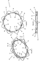
Figures 4-19 , thebody 12 may be formed with thesegments 14 being of equal lengths.Figures 4-10 show thebody 12 having eight of the living hinges 16 which separates thebody 12 into eight of thesegments 14. Alternatively, as shown inFigures 11-19 , thebody 12 may be formed with four of the living hinges 16 separating thebody 12 into four of thesegments 14. - The locations of the living hinges 16 and the lengths of the
segments 14 will affect the configuration of thebody 12 in the first state.Figure 2 , discussed above, provides a first state which is expandable outwardly along two Cartesian axes (represented inFigure 2 by "X" and "Y" arrows).Figures 7-10 ,11-13 and14-16 each show thebody 12 in a first state which is expandable outwardly along one Cartesian axis (represented inFigure 7 by "X" arrows). Here, thebody 12 is collapsed about two of the living hinges 16, which may be opposing, to define first and second ends 32, 34. Thelobes 18 are located exteriorly of all of thesegments 14. Thebody 12 may foreshorten along the perpendicular Cartesian axis during expansion (represented inFigure 7 by "Y" arrows) with this configuration. Living hinges 16 may be located at various mid-points between the first and second ends 32, 34 depending on the lengths of the correspondingsegments 14. Where thesegments 14 are of equal length, the living hinges 16 will be located generally centrally between the first and second ends 32, 34. The living hinges 16 not located at theends segments 14 in the first state. This allows for thesegments 14 to have natural at-rest arcuate shapes in the second state, yet be deformed to generally straight shapes with thebody 12 in the first state. The release of thesegments 14 from the deformed straight states to their natural at-rest states may impart force of expansion to thebody 12 where self-expansion thereof is desired. - One or more of the
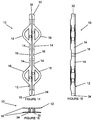
lobes 18 may be provided on thebody 12 for extending over a portion of the iris during implantation and/or expansion of theiris expander 10. A plurality of thelobes 18 may be spaced about thebody 12 at equal intervals along a single edge of thebody 12, such asfirst edge 24 of thebody 12. Thelobes 18 are positioned so that a portion of the iris is received adjacent thereto. This provides a locating function for theiris expander 10 relative to the iris and additional stability in while expanding thebody 12 and holding thebody 12 in the expanded state. - With reference to
Figure 3 , thelobes 18 may be provided along both thefirst edge 24 andsecond edge 26 of thebody 12. Thelobes 18 on the first andsecond edges body 12 so as to formU-shaped pockets 28 directly between a pair of thelobes 18 located above and below. Thepockets 28 may receive portions of the iris. Alternatively, with reference toFigures 4-6 , thelobes 18 may be spaced in equal intervals about each of thefirst edge 24 and thesecond edge 26 but out of phase between the first andsecond edges lobes 18 alternately protrude from the opposingedges body 12. This arrangement provides upper and lower stabilization without defining thepockets 28. - The
lobes 18 may be formed solidly (Figure 3 ) so as to be continuous or frame shaped (Figure 14 ) with portions thereof being open. In addition, thelobes 18 may be located centrally (Figure 4 ) or off-center (Figure 17 ) on thesegments 14. This allows for different positions of thelobes 18 with thebody 12 in the first state, as shown in comparingFigures 14-16 andFigure 20 . - As shown in
Figure 3 , one or more of thelobes 18 may include anaperture 20 from which extends achannel 22. Thechannel 22 is formed to accommodate a portion of an instrument for positioning thebody 12 and/or causing expansion of thebody 12. Thechannel 22 may be blind or may extend through therespective lobe 18 to asecond aperture 30 so as to be exposed externally of theadjacent segment 14. If thelobes 18 are frame shaped, the instrument may be inserted into an open portion thereof. - In a second embodiment of the invention, and with reference to
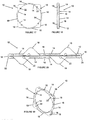
Figures 4-19 , thechannel 22 is located to extend through one of thesegments 14 with theaperture 20 being exposed on thefirst edge 24 of thebody 12 along the correspondingsegment 14. In this manner, thechannel 22 is embedded in thesegment 14 with no portion thereof exposed externally of thebody 12, as shown schematically inFigures 4A and 4B . Thechannel 22 is completely spaced inwardly from bothinner side surface 27 and theouter side surface 29 of thebody 12. This arrangement locates an instrument received in thechannel 22 out of axial alignment with the iris tissue. Thechannel 22 may be blind (Figure 4A ) or may extend to the second aperture 30 (Figure 4B ) which is exposed externally on thesecond edge 26. With this arrangement, an instrument engaged in thechannel 22 is located inwardly of the margin of the iris. Thus, even with the instrument extending through thesecond aperture 30, the instrument does not directly contact the iris. Preferably, thechannel 22 extends along a longitudinal axis which is transverse to the expansion plane. Further, a plurality of thechannels 22 may be provided in thebody 12, each with a correspondingaperture 20. Thechannel 22 may be evenly spaced about thebody 12. In addition, one of thelobes 18 may be located adjacent to each of thechannels 22. This allows for additional tissue stabilization at potential locations of force application for expansion. - With respect to the second embodiment, the placement of the
channel 22 wholly within thebody 12 may be utilized with various configurations of thebody 12 as described above with respect to the first embodiment. Thebody 12 can be multi-segmented with a plurality of thesegments 14. However, the living hinges 16 are not required for the second embodiment of the invention; various hinges, and other connections, between thesegments 14 may be utilized. In all other respects, the second embodiment may be practiced in the same manner as the first embodiment. - With reference to
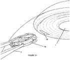
Figures 21-29 , various aspects of introducing and using theiris expander 10 is shown. Although a specific shape of thebody 12 is shown, it is to be understood that thebody 12 can be formed with any configuration discussed herein, including both the first and second embodiments. With reference toFigure 21 , acorneal incision 36 is initially made in a patient's eye to be treated. A typical corneal incision for cataract extraction may be utilized. Theiris expander 10 is introduced into the eye with thebody 12 being in the first, collapsed state. With theiris expander 10 being manually expandable, forceps F or other instruments may be used to insert theiris expander 10 through thecorneal incision 36 and locate theiris expander 10 within the iris I. Thereafter, theiris expander 10 is positioned so that the iris margin is aligned with at least a portion of the lobes 18 (Figure 23 ). One or more instruments, such as hooks H (e.g., Sinskey hooks), may be used to properly position the iris expander 10 (Figure 24 ).Secondary incisions 38 in the cornea may be utilized as needed. Preferably, as shown inFigure 25 , theiris expander 10 is manually expanded by applying force in generally opposing directions. As shown here,certain segments 14, such as theprimary segments 14A, may be first extended outwardly. This partial expansion of theiris expander 10 allows for partial expansion of the iris I. Thereafter, remaining portions of thebody 12 may be expanded, such as shown inFigure 26 . This continues until full expansion of theiris expander 10 is achieved. Once fully expanded (Figure 28 ), an ophthalmic procedure may be conducted. After the procedure, theiris expander 10 is collapsed and removed using a reverse procedure. - With self-expansion, the
iris expander 10 may be maintained in the first state by an introducer C inserted through the corneal incision 36 (Figure 29 ). The introducer C (e.g., a pusher plunger instrument) urges theiris expander 10 therefrom to be located within the iris I. With release, theiris expander 10 expands to the second state. An instrument, such as one or more hooks (e.g., Sinskey hooks), may be used to adjust the position of theiris expander 10 as necessary. Once fully expanded (Figure 28 ), an ophthalmic procedure may be conducted. After the procedure, theiris expander 10 is collapsed, e.g., by retraction into the introducer C.
Claims (13)
- An iris expander (10) comprising:
a non-metallic, unitary, multi-segmented body (12) which is expandable from a first state to a second state, said second state defining a larger footprint than said first state, said body (12) being a closed loop defined by a plurality of segments (14) connected by living hinges (16), wherein expansion of said body (12) in expanding from said first state to said second state is generally in an expansion plane, the segments (14) and said living hinges (16) extending continuously about the length of the body (12) so as to not allow iris tissue to extend therethrough, wherein at least one aperture (20) being formed in said body (12) with a channel (22) extending therefrom into a portion of said body (12), said channel (22) being embedded in said body (12) so as to be out of axial alignment with iris tissue during use with no portion thereof being exposed externally of said body, said channel (22) being formed to accommodate a portion of an instrument inwardly of a margin of the iris for causing adjustment of said body (12) without the accommodated portion of the instrument contacting the iris. - An iris expander (10) as in claim 1, wherein said body (12) includes at least one protruding lobe (18).
- An iris expander (10) as in claim 2, wherein a plurality of lobes (18) alternately protrude from opposing edges of said body (12).
- An iris expander (10) as in claim 2, wherein at least one pair of lobes (18) protrudes from said body (12) to define a U-shaped pocket (28) therebetween.
- An iris expander (10) as in claim 1, wherein a first of said segments (14) and a second of said segments (14) are configured to collectively generally bound all of the other segments (14) with said body (12) being in said first state.
- An iris expander (10) as in claim 5, wherein said first segment is arcuately shaped and said second segment is arcuately shaped, said first and second segments being positioned to bow outwardly from each other with said body (12) being in said first state.
- An iris expander (10) as in claim 1, wherein said channel (22) terminates at a second aperture (30) formed in said body (12).
- An iris expander (10) as in claim 1, wherein said channel (22) extends along a longitudinal axis disposed transverse to said expansion plane.
- An iris expander (10) as in claim 1, wherein a plurality of said apertures (20) are provided spaced about said body (12), a channel (22) extending from each said aperture (20) which is embedded in said body such that no portion thereof is exposed externally of said body (12).
- An iris expander (10) as in claim 9, wherein said plurality of apertures (20) are evenly spaced about said body (12).
- An iris expander (10) as in claim 1, wherein a first of said apertures (20) is formed in a first of said segments (14), a channel (22) extending from said first aperture which is embedded in said first segment such that no portion thereof is exposed externally of said first segment.
- An iris expander (10) as in claim 1, wherein said living hinges (16) are formed by thinned sections of said body (12) between adjacent pairs of said segments (14).
- An iris expander (10) as in any preceding claim, wherein said body (12) includes elastomeric material or thermoplastic material or thermoplastic/elastomeric copolymer.
Priority Applications (1)
| Application Number | Priority Date | Filing Date | Title |
|---|---|---|---|
| EP19179531.9A EP3560414A1 (en) | 2013-03-15 | 2014-03-17 | Iris expander |
Applications Claiming Priority (2)
| Application Number | Priority Date | Filing Date | Title |
|---|---|---|---|
| US201361788350P | 2013-03-15 | 2013-03-15 | |
| PCT/US2014/030550 WO2014145739A1 (en) | 2013-03-15 | 2014-03-17 | Iris expander |
Related Child Applications (1)
| Application Number | Title | Priority Date | Filing Date |
|---|---|---|---|
| EP19179531.9A Division EP3560414A1 (en) | 2013-03-15 | 2014-03-17 | Iris expander |
Publications (3)
| Publication Number | Publication Date |
|---|---|
| EP2956047A1 EP2956047A1 (en) | 2015-12-23 |
| EP2956047A4 EP2956047A4 (en) | 2016-04-27 |
| EP2956047B1 true EP2956047B1 (en) | 2019-06-12 |
Family
ID=51530983
Family Applications (2)
| Application Number | Title | Priority Date | Filing Date |
|---|---|---|---|
| EP19179531.9A Pending EP3560414A1 (en) | 2013-03-15 | 2014-03-17 | Iris expander |
| EP14762382.1A Active EP2956047B1 (en) | 2013-03-15 | 2014-03-17 | Iris expander |
Family Applications Before (1)
| Application Number | Title | Priority Date | Filing Date |
|---|---|---|---|
| EP19179531.9A Pending EP3560414A1 (en) | 2013-03-15 | 2014-03-17 | Iris expander |
Country Status (13)
| Country | Link |
|---|---|
| US (5) | US8900136B2 (en) |
| EP (2) | EP3560414A1 (en) |
| JP (6) | JP6064081B2 (en) |
| KR (3) | KR102268075B1 (en) |
| CN (2) | CN106963545B (en) |
| BR (1) | BR112015023666B1 (en) |
| CA (1) | CA2901850C (en) |
| DE (1) | DE212014000082U1 (en) |
| ES (1) | ES2744826T3 (en) |
| IL (1) | IL241169B (en) |
| MX (1) | MX2015010771A (en) |
| RU (1) | RU2653555C2 (en) |
| WO (1) | WO2014145739A1 (en) |
Families Citing this family (27)
| Publication number | Priority date | Publication date | Assignee | Title |
|---|---|---|---|---|
| US8323296B2 (en) | 2007-03-15 | 2012-12-04 | Boris Malyugin | Ring used in a small pupil phacoemulsification procedure |
| US9918710B2 (en) | 2007-03-15 | 2018-03-20 | Microsurgical Technology, Inc. | Expansion ring for eyeball tissue |
| US8439833B2 (en) * | 2011-10-18 | 2013-05-14 | Oasis Medical, Inc. | Ophthalmic structure |
| USD735857S1 (en) * | 2012-10-31 | 2015-08-04 | Ronald Eugene Dykes | Pupil expander |
| US20140221759A1 (en) * | 2013-02-06 | 2014-08-07 | Impex, Inc. | Pupil expansion apparatus |
| WO2014132264A1 (en) * | 2013-02-27 | 2014-09-04 | Bhattacharjee Suven | Device providing enlargement & preventing collapse of the pupil of the eye |
| ES2744826T3 (en) | 2013-03-15 | 2020-02-26 | Beaver Visitec Int Us Inc | Iris Dilator |
| JP5528599B1 (en) * | 2013-03-29 | 2014-06-25 | 株式会社Frontier Vision | Pupil dilator |
| JP5528600B1 (en) * | 2013-03-29 | 2014-06-25 | 株式会社Frontier Vision | Pupil dilator |
| US20140378773A1 (en) | 2013-06-19 | 2014-12-25 | Ronald Dykes | Intraocular Expansion and Retention Devices and Methods |
| US10307150B2 (en) * | 2014-06-26 | 2019-06-04 | The Regents Of The University Of Colorado, A Body Corporate | Ocular tissue expansion ring |
| US20160367397A1 (en) * | 2014-08-12 | 2016-12-22 | Katalyst Surgical, Llc | Multi-function capsulorhexis guide |
| US9504459B1 (en) | 2015-06-30 | 2016-11-29 | Ravi Nallakrishnan Revocable Trust | Surgical apparatus and method of use thereof |
| WO2017020099A1 (en) * | 2015-07-31 | 2017-02-09 | Canabrava Sérgio Félix | Iris dilating ring for cataract surgery without injector |
| KR101592975B1 (en) * | 2015-08-19 | 2016-02-12 | 위캔메디케어 주식회사 | Surgical retractor |
| SG10201912531YA (en) * | 2015-10-20 | 2020-02-27 | Nat Univ Singapore | Expander for holding apart an opening in a tissue and method of operating the same |
| KR102506627B1 (en) * | 2017-03-29 | 2023-03-07 | 보스톤 싸이엔티픽 싸이메드 인코포레이티드 | Devices and methods for tissue retraction |
| WO2019040836A1 (en) * | 2017-08-25 | 2019-02-28 | Zacharia Peter | Eye surgery device |
| US11395761B2 (en) | 2018-10-03 | 2022-07-26 | Realens, Inc. | Iris shield |
| USD928954S1 (en) * | 2018-10-05 | 2021-08-24 | Koh Young Technology Inc. | Clamp for surgical instrument |
| US11759101B2 (en) * | 2019-03-15 | 2023-09-19 | Modern Surgical Solutions Llc | Retractor for vaginal repair |
| CN109998613A (en) * | 2019-04-19 | 2019-07-12 | 郑州大学第一附属医院 | The iris extension fixture of corneal incision wound can be reduced |
| WO2021007287A1 (en) * | 2019-07-09 | 2021-01-14 | Tal Michael Gabriel | Toggling vascular access port |
| WO2021050852A1 (en) * | 2019-09-12 | 2021-03-18 | Foulkes Richard B | An intraocular clipping device |
| CN111345937A (en) * | 2020-03-12 | 2020-06-30 | 江苏康视佳医疗器械有限公司 | Integral type iris expander |
| US11571333B2 (en) | 2020-05-18 | 2023-02-07 | Refocus Group, Inc. | Apparatus and method for securing ocular tissue and providing surgical tool positioning points |
| CN115666463A (en) * | 2020-06-26 | 2023-01-31 | 株式会社明日视界 | Pupil dilator |
Family Cites Families (56)
| Publication number | Priority date | Publication date | Assignee | Title |
|---|---|---|---|---|
| US2053868A (en) * | 1934-01-09 | 1936-09-08 | Patrick P Grosso | Universal self-retaining retractor |
| US2845925A (en) | 1953-11-24 | 1958-08-05 | Jayle Gaetan Jean | Automatic eyelids eyeball fixing device for a surgical intervention |
| US3490455A (en) | 1965-05-17 | 1970-01-20 | Karl M Illig | Surgical device |
| US4037589A (en) | 1975-10-03 | 1977-07-26 | William U. McReynolds | Ocular surgical system |
| US4257406A (en) | 1979-05-18 | 1981-03-24 | Schenk Alan G | Iris retractor and pupil dilator |
| SU944558A1 (en) * | 1980-06-25 | 1982-07-23 | Иркутский Государственный Медицинский Институт | Pupil dilator |
| US4387706A (en) * | 1981-04-10 | 1983-06-14 | Glass Robert M | Iris retractor |
| US4782820A (en) | 1987-10-22 | 1988-11-08 | Woods Randall L | Iris retaining device |
| US4991567A (en) | 1990-01-16 | 1991-02-12 | Mccuen Ii Brooks W | Micro-iris retractor |
| US5174279A (en) | 1991-03-06 | 1992-12-29 | Duke University Medical Center | Iris retractor for use in operations on the eye of a living creature |
| US5163419A (en) * | 1991-04-04 | 1992-11-17 | Goldman Kenneth N | Device for expanding the pupil of a human eye |
| US5318011A (en) | 1992-02-04 | 1994-06-07 | Escalon Ophthalmics, Inc. | Iris protector/dilator and method of using the same |
| US5427088A (en) | 1992-02-18 | 1995-06-27 | Graether; John M. | Apparatus for inserting a pupil expander |
| US5322054A (en) | 1992-02-18 | 1994-06-21 | Graether John M | Pupil expander carrier and means for manipulating a pupil expander |
| US5634884A (en) | 1992-02-18 | 1997-06-03 | Graether Development Corporation | Apparatus for inserting a pupil expander |
| US5267553A (en) * | 1992-02-18 | 1993-12-07 | Graether John M | Pupil expander and method of using the same |
| US5299564A (en) | 1992-09-23 | 1994-04-05 | Kabi Pharmacia Ophthalmics Inc. | Expandable dilator and method for intraocular surgery |
| US5374272A (en) * | 1993-06-29 | 1994-12-20 | Vitrophage, Inc. | Apparatus and method for mechanically dilating the pupil of an eye |
| EP0731670A1 (en) * | 1993-11-30 | 1996-09-18 | John M. Graether | Pupil expander and method of using the same |
| US5514076A (en) | 1994-01-27 | 1996-05-07 | Flexmedics Corporation | Surgical retractor |
| US5607446A (en) | 1995-01-31 | 1997-03-04 | Beehler; Cecil C. | Pupil dilator |
| DE19538951C2 (en) | 1995-10-19 | 1998-04-30 | Detlef H Dr Holzwig | Device for spreading an eye iris |
| AU712377B2 (en) | 1996-03-26 | 1999-11-04 | Milvella Pty Ltd | Device for dilating a pupil and/or maintaining a pupil in a dilated state |
| US6068643A (en) * | 1996-03-26 | 2000-05-30 | Milvella Pty. Ltd. | Device for dilating a pupil and/or maintaining a pupil in a dilated state |
| US5716328A (en) | 1996-08-07 | 1998-02-10 | Grieshaber & Co. Ag Schaffhausen | Iris retractor for use in surgical procedure on the eye of a living being |
| US5807244A (en) | 1996-11-15 | 1998-09-15 | Barot; Jagdish Shantilal | Single use disposable iris retractor |
| US5846192A (en) * | 1997-10-31 | 1998-12-08 | Teixido-Longworth Partnership | Polymeric surgical retractor |
| US6162172A (en) * | 1998-01-30 | 2000-12-19 | Edwards Lifesciences Corporation | Methods and apparatus for retracting tissue |
| AUPP747398A0 (en) | 1998-12-03 | 1998-12-24 | Milvella Pty Ltd | Device for dilating a pupil and/or maintaining a pupil in a dilated state |
| US6332866B1 (en) | 2000-03-21 | 2001-12-25 | Grieshaber & Co. Ag Schaffhausen | Iris retractor for use in surgical procedure on the eye of a living being |
| US6561974B1 (en) | 2000-05-31 | 2003-05-13 | Grieshaber & Co. Ag Schaffhausen | Device for use in a surgical procedure on an eye of a living being, and method of retracting the iris |
| FR2827497A1 (en) * | 2001-07-19 | 2003-01-24 | Francois Deschatres | Support for holding eyelids open during surgical procedure comprises one-piece component with grooves for lids and central aperture for access |
| US6648819B2 (en) * | 2001-11-15 | 2003-11-18 | Yau Wing Lee | Pupil dilator |
| AU2002317086A1 (en) | 2002-06-28 | 2004-02-16 | 3062696 Nova Scotia Limited | Pupil dilating device and apparatus for use therewith |
| DE102004027236B4 (en) | 2004-06-03 | 2006-04-13 | Morcher Gmbh | Capsular equatorial ring |
| RU2295941C1 (en) | 2005-09-07 | 2007-03-27 | Федеральное государственное учреждение "Межотраслевой научно-технический комплекс "Микрохирургия глаза" им. акад. С.Н. Федорова Федерального агентства по здравоохранению и социальному развитию" | Method and device for extracting cataract with intraocular lens being implanted under narrow pupil condition |
| WO2007141588A1 (en) * | 2006-06-02 | 2007-12-13 | Nokia Corporation | Split exit pupil expander |
| CN200966677Y (en) | 2006-11-15 | 2007-10-31 | 姚晓明 | Pupilla extending device |
| US20080188860A1 (en) | 2007-02-07 | 2008-08-07 | Vold Steven D | Ophthalmic surgical apparatus |
| USD573711S1 (en) * | 2007-03-01 | 2008-07-22 | Ethicon Endo-Surgery, Inc. | Iris valve ring |
| US9918710B2 (en) * | 2007-03-15 | 2018-03-20 | Microsurgical Technology, Inc. | Expansion ring for eyeball tissue |
| US8323296B2 (en) * | 2007-03-15 | 2012-12-04 | Boris Malyugin | Ring used in a small pupil phacoemulsification procedure |
| US20120289786A1 (en) * | 2010-11-09 | 2012-11-15 | Microsurgical Technology, Inc. | Extension ring for eyeball tissue |
| US20080243139A1 (en) | 2007-03-15 | 2008-10-02 | Vaclav Dusek | Method for assembling a ring used in a small pupil phaco procedure |
| DE202007010335U1 (en) * | 2007-07-23 | 2007-10-11 | Rümpler, Lars, Dr. | Tensioning ring for temporary implantation in the human eye for pupil dilation |
| US9078995B2 (en) | 2010-05-13 | 2015-07-14 | Xygent Vision Care Insight | Iris retraction balloon for phacoemulsification |
| WO2012037550A1 (en) | 2010-09-17 | 2012-03-22 | Henry Ford Health System | Pupil ring |
| US8439833B2 (en) * | 2011-10-18 | 2013-05-14 | Oasis Medical, Inc. | Ophthalmic structure |
| US8852091B2 (en) | 2012-04-04 | 2014-10-07 | Alcon Research, Ltd. | Devices, systems, and methods for pupil expansion |
| RU122576U1 (en) | 2012-07-10 | 2012-12-10 | Федеральное государственное бюджетное учреждение "Межотраслевой научно-технический комплекс "Микрохирургия глаза" имени академика С.Н. Федорова Министерства здравоохранения и социального развития Российской Федерации" | DEVICE FOR EXTENSION OF THE PUPPET AND FIXATION OF THE CAPSULE BAG |
| SI2911623T1 (en) * | 2012-10-26 | 2019-12-31 | Forsight Vision5, Inc. | Ophthalmic system for sustained release of drug to eye |
| US8496583B1 (en) | 2012-11-03 | 2013-07-30 | Michael Reynard | Pupil dilation system |
| US20140221759A1 (en) * | 2013-02-06 | 2014-08-07 | Impex, Inc. | Pupil expansion apparatus |
| ES2744826T3 (en) * | 2013-03-15 | 2020-02-26 | Beaver Visitec Int Us Inc | Iris Dilator |
| JP5528599B1 (en) * | 2013-03-29 | 2014-06-25 | 株式会社Frontier Vision | Pupil dilator |
| JP5528600B1 (en) * | 2013-03-29 | 2014-06-25 | 株式会社Frontier Vision | Pupil dilator |
-
2014
- 2014-03-17 ES ES14762382T patent/ES2744826T3/en active Active
- 2014-03-17 CA CA2901850A patent/CA2901850C/en active Active
- 2014-03-17 KR KR1020157025333A patent/KR102268075B1/en active IP Right Grant
- 2014-03-17 EP EP19179531.9A patent/EP3560414A1/en active Pending
- 2014-03-17 DE DE212014000082.3U patent/DE212014000082U1/en not_active Expired - Lifetime
- 2014-03-17 CN CN201710284415.XA patent/CN106963545B/en active Active
- 2014-03-17 MX MX2015010771A patent/MX2015010771A/en active IP Right Grant
- 2014-03-17 EP EP14762382.1A patent/EP2956047B1/en active Active
- 2014-03-17 JP JP2016503418A patent/JP6064081B2/en active Active
- 2014-03-17 KR KR1020217018616A patent/KR102390631B1/en active IP Right Grant
- 2014-03-17 RU RU2015144291A patent/RU2653555C2/en active
- 2014-03-17 CN CN201480019545.5A patent/CN105188514B/en active Active
- 2014-03-17 BR BR112015023666-9A patent/BR112015023666B1/en active IP Right Grant
- 2014-03-17 KR KR1020227013353A patent/KR102549793B1/en active IP Right Grant
- 2014-03-17 US US14/216,013 patent/US8900136B2/en active Active
- 2014-03-17 WO PCT/US2014/030550 patent/WO2014145739A1/en active Application Filing
- 2014-11-25 US US14/553,642 patent/US9579094B2/en active Active
-
2015
- 2015-09-03 IL IL241169A patent/IL241169B/en active IP Right Grant
-
2016
- 2016-12-19 JP JP2016245422A patent/JP6337075B2/en active Active
-
2017
- 2017-02-07 US US15/426,475 patent/US10433828B2/en active Active
-
2018
- 2018-05-07 JP JP2018089155A patent/JP6662945B2/en active Active
-
2019
- 2019-09-10 US US16/565,961 patent/US11389150B2/en active Active
-
2020
- 2020-02-13 JP JP2020022728A patent/JP7069231B2/en active Active
-
2022
- 2022-05-02 JP JP2022076047A patent/JP7389172B2/en active Active
- 2022-06-24 US US17/849,053 patent/US20220313237A1/en active Pending
-
2023
- 2023-11-16 JP JP2023195384A patent/JP2024003234A/en active Pending
Non-Patent Citations (1)
| Title |
|---|
| None * |
Also Published As
Similar Documents
| Publication | Publication Date | Title |
|---|---|---|
| US20220313237A1 (en) | Iris expander | |
| JP6495827B2 (en) | Capsule expander device, system, and method for preventing sac turbidity and stabilizing sac | |
| JP5528600B1 (en) | Pupil dilator | |
| EP3364852B1 (en) | Expander for holding apart an opening in a tissue |
Legal Events
| Date | Code | Title | Description |
|---|---|---|---|
| PUAI | Public reference made under article 153(3) epc to a published international application that has entered the european phase |
Free format text: ORIGINAL CODE: 0009012 |
|
| 17P | Request for examination filed |
Effective date: 20150916 |
|
| AK | Designated contracting states |
Kind code of ref document: A1 Designated state(s): AL AT BE BG CH CY CZ DE DK EE ES FI FR GB GR HR HU IE IS IT LI LT LU LV MC MK MT NL NO PL PT RO RS SE SI SK SM TR |
|
| AX | Request for extension of the european patent |
Extension state: BA ME |
|
| A4 | Supplementary search report drawn up and despatched |
Effective date: 20160330 |
|
| RIC1 | Information provided on ipc code assigned before grant |
Ipc: A61B 1/32 20060101AFI20160322BHEP Ipc: A61B 17/02 20060101ALI20160322BHEP |
|
| DAX | Request for extension of the european patent (deleted) | ||
| R17P | Request for examination filed (corrected) |
Effective date: 20150916 |
|
| 17Q | First examination report despatched |
Effective date: 20160823 |
|
| STAA | Information on the status of an ep patent application or granted ep patent |
Free format text: STATUS: EXAMINATION IS IN PROGRESS |
|
| GRAP | Despatch of communication of intention to grant a patent |
Free format text: ORIGINAL CODE: EPIDOSNIGR1 |
|
| STAA | Information on the status of an ep patent application or granted ep patent |
Free format text: STATUS: GRANT OF PATENT IS INTENDED |
|
| INTG | Intention to grant announced |
Effective date: 20190107 |
|
| GRAS | Grant fee paid |
Free format text: ORIGINAL CODE: EPIDOSNIGR3 |
|
| GRAA | (expected) grant |
Free format text: ORIGINAL CODE: 0009210 |
|
| STAA | Information on the status of an ep patent application or granted ep patent |
Free format text: STATUS: THE PATENT HAS BEEN GRANTED |
|
| AK | Designated contracting states |
Kind code of ref document: B1 Designated state(s): AL AT BE BG CH CY CZ DE DK EE ES FI FR GB GR HR HU IE IS IT LI LT LU LV MC MK MT NL NO PL PT RO RS SE SI SK SM TR |
|
| REG | Reference to a national code |
Ref country code: GB Ref legal event code: FG4D |
|
| REG | Reference to a national code |
Ref country code: CH Ref legal event code: EP |
|
| REG | Reference to a national code |
Ref country code: AT Ref legal event code: REF Ref document number: 1141494 Country of ref document: AT Kind code of ref document: T Effective date: 20190615 |
|
| REG | Reference to a national code |
Ref country code: DE Ref legal event code: R096 Ref document number: 602014048234 Country of ref document: DE |
|
| REG | Reference to a national code |
Ref country code: IE Ref legal event code: FG4D |
|
| REG | Reference to a national code |
Ref country code: DE Ref legal event code: R081 Ref document number: 602014048234 Country of ref document: DE Owner name: BEAVER-VISITEC INTERNATIONAL (US), INC., WALTH, US Free format text: FORMER OWNER: BEAVER-VISITEC INTERNATIONAL (US), INC., LAKE FOREST, ILL., US |
|
| REG | Reference to a national code |
Ref country code: NL Ref legal event code: MP Effective date: 20190612 |
|
| REG | Reference to a national code |
Ref country code: LT Ref legal event code: MG4D |
|
| RAP2 | Party data changed (patent owner data changed or rights of a patent transferred) |
Owner name: BEAVER-VISITEC INTERNATIONAL (US), INC. |
|
| PG25 | Lapsed in a contracting state [announced via postgrant information from national office to epo] |
Ref country code: HR Free format text: LAPSE BECAUSE OF FAILURE TO SUBMIT A TRANSLATION OF THE DESCRIPTION OR TO PAY THE FEE WITHIN THE PRESCRIBED TIME-LIMIT Effective date: 20190612 Ref country code: LT Free format text: LAPSE BECAUSE OF FAILURE TO SUBMIT A TRANSLATION OF THE DESCRIPTION OR TO PAY THE FEE WITHIN THE PRESCRIBED TIME-LIMIT Effective date: 20190612 Ref country code: AL Free format text: LAPSE BECAUSE OF FAILURE TO SUBMIT A TRANSLATION OF THE DESCRIPTION OR TO PAY THE FEE WITHIN THE PRESCRIBED TIME-LIMIT Effective date: 20190612 Ref country code: FI Free format text: LAPSE BECAUSE OF FAILURE TO SUBMIT A TRANSLATION OF THE DESCRIPTION OR TO PAY THE FEE WITHIN THE PRESCRIBED TIME-LIMIT Effective date: 20190612 Ref country code: SE Free format text: LAPSE BECAUSE OF FAILURE TO SUBMIT A TRANSLATION OF THE DESCRIPTION OR TO PAY THE FEE WITHIN THE PRESCRIBED TIME-LIMIT Effective date: 20190612 Ref country code: NO Free format text: LAPSE BECAUSE OF FAILURE TO SUBMIT A TRANSLATION OF THE DESCRIPTION OR TO PAY THE FEE WITHIN THE PRESCRIBED TIME-LIMIT Effective date: 20190912 |
|
| PG25 | Lapsed in a contracting state [announced via postgrant information from national office to epo] |
Ref country code: GR Free format text: LAPSE BECAUSE OF FAILURE TO SUBMIT A TRANSLATION OF THE DESCRIPTION OR TO PAY THE FEE WITHIN THE PRESCRIBED TIME-LIMIT Effective date: 20190913 Ref country code: RS Free format text: LAPSE BECAUSE OF FAILURE TO SUBMIT A TRANSLATION OF THE DESCRIPTION OR TO PAY THE FEE WITHIN THE PRESCRIBED TIME-LIMIT Effective date: 20190612 Ref country code: BG Free format text: LAPSE BECAUSE OF FAILURE TO SUBMIT A TRANSLATION OF THE DESCRIPTION OR TO PAY THE FEE WITHIN THE PRESCRIBED TIME-LIMIT Effective date: 20190912 Ref country code: LV Free format text: LAPSE BECAUSE OF FAILURE TO SUBMIT A TRANSLATION OF THE DESCRIPTION OR TO PAY THE FEE WITHIN THE PRESCRIBED TIME-LIMIT Effective date: 20190612 |
|
| REG | Reference to a national code |
Ref country code: AT Ref legal event code: MK05 Ref document number: 1141494 Country of ref document: AT Kind code of ref document: T Effective date: 20190612 |
|
| PG25 | Lapsed in a contracting state [announced via postgrant information from national office to epo] |
Ref country code: EE Free format text: LAPSE BECAUSE OF FAILURE TO SUBMIT A TRANSLATION OF THE DESCRIPTION OR TO PAY THE FEE WITHIN THE PRESCRIBED TIME-LIMIT Effective date: 20190612 Ref country code: AT Free format text: LAPSE BECAUSE OF FAILURE TO SUBMIT A TRANSLATION OF THE DESCRIPTION OR TO PAY THE FEE WITHIN THE PRESCRIBED TIME-LIMIT Effective date: 20190612 Ref country code: SK Free format text: LAPSE BECAUSE OF FAILURE TO SUBMIT A TRANSLATION OF THE DESCRIPTION OR TO PAY THE FEE WITHIN THE PRESCRIBED TIME-LIMIT Effective date: 20190612 Ref country code: CZ Free format text: LAPSE BECAUSE OF FAILURE TO SUBMIT A TRANSLATION OF THE DESCRIPTION OR TO PAY THE FEE WITHIN THE PRESCRIBED TIME-LIMIT Effective date: 20190612 Ref country code: PT Free format text: LAPSE BECAUSE OF FAILURE TO SUBMIT A TRANSLATION OF THE DESCRIPTION OR TO PAY THE FEE WITHIN THE PRESCRIBED TIME-LIMIT Effective date: 20191014 Ref country code: RO Free format text: LAPSE BECAUSE OF FAILURE TO SUBMIT A TRANSLATION OF THE DESCRIPTION OR TO PAY THE FEE WITHIN THE PRESCRIBED TIME-LIMIT Effective date: 20190612 Ref country code: NL Free format text: LAPSE BECAUSE OF FAILURE TO SUBMIT A TRANSLATION OF THE DESCRIPTION OR TO PAY THE FEE WITHIN THE PRESCRIBED TIME-LIMIT Effective date: 20190612 |
|
| REG | Reference to a national code |
Ref country code: ES Ref legal event code: FG2A Ref document number: 2744826 Country of ref document: ES Kind code of ref document: T3 Effective date: 20200226 |
|
| PG25 | Lapsed in a contracting state [announced via postgrant information from national office to epo] |
Ref country code: IS Free format text: LAPSE BECAUSE OF FAILURE TO SUBMIT A TRANSLATION OF THE DESCRIPTION OR TO PAY THE FEE WITHIN THE PRESCRIBED TIME-LIMIT Effective date: 20191012 Ref country code: SM Free format text: LAPSE BECAUSE OF FAILURE TO SUBMIT A TRANSLATION OF THE DESCRIPTION OR TO PAY THE FEE WITHIN THE PRESCRIBED TIME-LIMIT Effective date: 20190612 |
|
| REG | Reference to a national code |
Ref country code: DE Ref legal event code: R097 Ref document number: 602014048234 Country of ref document: DE |
|
| PG25 | Lapsed in a contracting state [announced via postgrant information from national office to epo] |
Ref country code: TR Free format text: LAPSE BECAUSE OF FAILURE TO SUBMIT A TRANSLATION OF THE DESCRIPTION OR TO PAY THE FEE WITHIN THE PRESCRIBED TIME-LIMIT Effective date: 20190612 |
|
| PLBE | No opposition filed within time limit |
Free format text: ORIGINAL CODE: 0009261 |
|
| STAA | Information on the status of an ep patent application or granted ep patent |
Free format text: STATUS: NO OPPOSITION FILED WITHIN TIME LIMIT |
|
| PG25 | Lapsed in a contracting state [announced via postgrant information from national office to epo] |
Ref country code: DK Free format text: LAPSE BECAUSE OF FAILURE TO SUBMIT A TRANSLATION OF THE DESCRIPTION OR TO PAY THE FEE WITHIN THE PRESCRIBED TIME-LIMIT Effective date: 20190612 Ref country code: PL Free format text: LAPSE BECAUSE OF FAILURE TO SUBMIT A TRANSLATION OF THE DESCRIPTION OR TO PAY THE FEE WITHIN THE PRESCRIBED TIME-LIMIT Effective date: 20190612 |
|
| 26N | No opposition filed |
Effective date: 20200313 |
|
| PG25 | Lapsed in a contracting state [announced via postgrant information from national office to epo] |
Ref country code: IS Free format text: LAPSE BECAUSE OF FAILURE TO SUBMIT A TRANSLATION OF THE DESCRIPTION OR TO PAY THE FEE WITHIN THE PRESCRIBED TIME-LIMIT Effective date: 20200224 Ref country code: SI Free format text: LAPSE BECAUSE OF FAILURE TO SUBMIT A TRANSLATION OF THE DESCRIPTION OR TO PAY THE FEE WITHIN THE PRESCRIBED TIME-LIMIT Effective date: 20190612 |
|
| PG2D | Information on lapse in contracting state deleted |
Ref country code: IS |
|
| PG25 | Lapsed in a contracting state [announced via postgrant information from national office to epo] |
Ref country code: MC Free format text: LAPSE BECAUSE OF FAILURE TO SUBMIT A TRANSLATION OF THE DESCRIPTION OR TO PAY THE FEE WITHIN THE PRESCRIBED TIME-LIMIT Effective date: 20190612 |
|
| REG | Reference to a national code |
Ref country code: CH Ref legal event code: PL |
|
| REG | Reference to a national code |
Ref country code: BE Ref legal event code: MM Effective date: 20200331 |
|
| PG25 | Lapsed in a contracting state [announced via postgrant information from national office to epo] |
Ref country code: LU Free format text: LAPSE BECAUSE OF NON-PAYMENT OF DUE FEES Effective date: 20200317 |
|
| PG25 | Lapsed in a contracting state [announced via postgrant information from national office to epo] |
Ref country code: CH Free format text: LAPSE BECAUSE OF NON-PAYMENT OF DUE FEES Effective date: 20200331 Ref country code: IE Free format text: LAPSE BECAUSE OF NON-PAYMENT OF DUE FEES Effective date: 20200317 Ref country code: LI Free format text: LAPSE BECAUSE OF NON-PAYMENT OF DUE FEES Effective date: 20200331 |
|
| PG25 | Lapsed in a contracting state [announced via postgrant information from national office to epo] |
Ref country code: BE Free format text: LAPSE BECAUSE OF NON-PAYMENT OF DUE FEES Effective date: 20200331 |
|
| PG25 | Lapsed in a contracting state [announced via postgrant information from national office to epo] |
Ref country code: MT Free format text: LAPSE BECAUSE OF FAILURE TO SUBMIT A TRANSLATION OF THE DESCRIPTION OR TO PAY THE FEE WITHIN THE PRESCRIBED TIME-LIMIT Effective date: 20190612 Ref country code: CY Free format text: LAPSE BECAUSE OF FAILURE TO SUBMIT A TRANSLATION OF THE DESCRIPTION OR TO PAY THE FEE WITHIN THE PRESCRIBED TIME-LIMIT Effective date: 20190612 |
|
| PG25 | Lapsed in a contracting state [announced via postgrant information from national office to epo] |
Ref country code: MK Free format text: LAPSE BECAUSE OF FAILURE TO SUBMIT A TRANSLATION OF THE DESCRIPTION OR TO PAY THE FEE WITHIN THE PRESCRIBED TIME-LIMIT Effective date: 20190612 |
|
| PGFP | Annual fee paid to national office [announced via postgrant information from national office to epo] |
Ref country code: FR Payment date: 20230327 Year of fee payment: 10 |
|
| PGFP | Annual fee paid to national office [announced via postgrant information from national office to epo] |
Ref country code: IT Payment date: 20230321 Year of fee payment: 10 Ref country code: GB Payment date: 20230327 Year of fee payment: 10 Ref country code: DE Payment date: 20230329 Year of fee payment: 10 |
|
| PGFP | Annual fee paid to national office [announced via postgrant information from national office to epo] |
Ref country code: ES Payment date: 20230403 Year of fee payment: 10 |