EP2955913A1 - Caméra à fonction plenoptique hybride - Google Patents
Caméra à fonction plenoptique hybride Download PDFInfo
- Publication number
- EP2955913A1 EP2955913A1 EP14305870.9A EP14305870A EP2955913A1 EP 2955913 A1 EP2955913 A1 EP 2955913A1 EP 14305870 A EP14305870 A EP 14305870A EP 2955913 A1 EP2955913 A1 EP 2955913A1
- Authority
- EP
- European Patent Office
- Prior art keywords
- micro
- image sensor
- plenoptic camera
- lens array
- image
- Prior art date
- Legal status (The legal status is an assumption and is not a legal conclusion. Google has not performed a legal analysis and makes no representation as to the accuracy of the status listed.)
- Withdrawn
Links
Images

Classifications
-
- H—ELECTRICITY
- H04—ELECTRIC COMMUNICATION TECHNIQUE
- H04N—PICTORIAL COMMUNICATION, e.g. TELEVISION
- H04N23/00—Cameras or camera modules comprising electronic image sensors; Control thereof
- H04N23/58—Means for changing the camera field of view without moving the camera body, e.g. nutating or panning of optics or image sensors
-
- G—PHYSICS
- G02—OPTICS
- G02B—OPTICAL ELEMENTS, SYSTEMS OR APPARATUS
- G02B3/00—Simple or compound lenses
- G02B3/0006—Arrays
-
- G—PHYSICS
- G02—OPTICS
- G02B—OPTICAL ELEMENTS, SYSTEMS OR APPARATUS
- G02B7/00—Mountings, adjusting means, or light-tight connections, for optical elements
- G02B7/02—Mountings, adjusting means, or light-tight connections, for optical elements for lenses
- G02B7/023—Mountings, adjusting means, or light-tight connections, for optical elements for lenses permitting adjustment
-
- G—PHYSICS
- G06—COMPUTING; CALCULATING OR COUNTING
- G06T—IMAGE DATA PROCESSING OR GENERATION, IN GENERAL
- G06T3/00—Geometric image transformation in the plane of the image
- G06T3/40—Scaling the whole image or part thereof
- G06T3/4015—Demosaicing, e.g. colour filter array [CFA], Bayer pattern
-
- H—ELECTRICITY
- H04—ELECTRIC COMMUNICATION TECHNIQUE
- H04N—PICTORIAL COMMUNICATION, e.g. TELEVISION
- H04N23/00—Cameras or camera modules comprising electronic image sensors; Control thereof
- H04N23/50—Constructional details
- H04N23/54—Mounting of pick-up tubes, electronic image sensors, deviation or focusing coils
-
- H—ELECTRICITY
- H04—ELECTRIC COMMUNICATION TECHNIQUE
- H04N—PICTORIAL COMMUNICATION, e.g. TELEVISION
- H04N23/00—Cameras or camera modules comprising electronic image sensors; Control thereof
- H04N23/60—Control of cameras or camera modules
-
- H—ELECTRICITY
- H04—ELECTRIC COMMUNICATION TECHNIQUE
- H04N—PICTORIAL COMMUNICATION, e.g. TELEVISION
- H04N23/00—Cameras or camera modules comprising electronic image sensors; Control thereof
- H04N23/95—Computational photography systems, e.g. light-field imaging systems
- H04N23/957—Light-field or plenoptic cameras or camera modules
-
- H—ELECTRICITY
- H04—ELECTRIC COMMUNICATION TECHNIQUE
- H04N—PICTORIAL COMMUNICATION, e.g. TELEVISION
- H04N25/00—Circuitry of solid-state image sensors [SSIS]; Control thereof
- H04N25/48—Increasing resolution by shifting the sensor relative to the scene
-
- H—ELECTRICITY
- H04—ELECTRIC COMMUNICATION TECHNIQUE
- H04N—PICTORIAL COMMUNICATION, e.g. TELEVISION
- H04N5/00—Details of television systems
- H04N5/04—Synchronising
Definitions
- This invention relates to a plenoptic camera.
- a plenoptic camera sometimes referred to as a light-field camera, typically includes an array of micro-lenses located proximate the focal plane of the camera. This feature of the plenoptic camera allows it to capture the light field of a scene. With the aid of a computer, a user can post-process the light field captured by the plenoptic camera to reconstruct images of the scene from different points of view. Further, the user can also change the focus point of the images captured by the plenoptic camera.
- the plenoptic camera includes extra optical components, (i.e., the micro-lens array), which enables the camera to achieve the goals mentioned above.
- the plenoptic camera includes extra optical components, (i.e., the micro-lens array), which enables the camera to achieve the goals mentioned above.
- the plenoptic camera There presently exist at least two different types of plenoptic cameras.
- a first type of plenoptic camera as exemplified by the plenoptic camera manufactured by Lytro, Inc., Mountain View, California USA, has its array of micro-lenses located one focal length from the camera image sensor. All the micro-lenses in the array have the same focal length. This micro-lens configuration affords a maximum angular resolution but a low spatial resolution.
- the second type of plenoptic camera as exemplified by the plenoptic camera manufactured by Raytrix GmbH, Kiel, Germany, has a micro-lens array with three types of micro-lenses.
- This type of plenoptic camera is characterized by the fact that the image of the main lens does not form onto the micro-lenses, but onto a surface in the air. This surface is then set as the object, which is then imaged on the sensor by the micro-lens array.
- the three different types of micro-lenses provide a bigger depth of field as compared to a micro-lens array having the same kind of micro-lenses.
- This type of plenoptic camera sacrifices angular resolution for better spatial resolution because the micro-lenses are focused on the main image, getting more spatial resolution, and less angular resolution.
- a Bayer-pattern color filter filters light incident on the individual light-sending elements of the camera image sensor, thereby enabling the camera image sensor to capture color information in a roughly sampled image.
- This sampled image contains small sub-images formed under each micro-lens.
- the sub-image formed under each micro-lens actually becomes the sampled image of the exit pupil of the main camera lens seen by that micro-lens.
- This sub-image contains angular information of the light field.
- Concatenating the pixels taken from a fixed position under each micro-lens yields an image of the captured scene from a certain viewpoint.
- view de-multiplexing will refer to the process of extracting the pixels to form an image of the captured scene from the particular viewpoint.
- the resultant captured image can undergo de-mosaicking after de-multiplexing the views.
- the pixels under each micro-lens contain the information from different positions of the scene, de-mosaicking of such images (the raw data) yields little useful information and suffers from view crosstalk.
- the hexagonal arrangement of the micro-lenses result in patterns that suffer from irregularity and severe monochromaticism, i.e., the color sampling of the scene suffers from big spatial gaps between samples of different color channels.
- a processor will pre-process the captured image to obtain the information of three channels in every neighborhood of the view.
- This pre-processing includes calculating disparity maps that guide the de-mosaicking algorithm. In practice, however, the results of such preprocessing yield much lower quality than the de-mosaicking of the raw data.
- the plenoptic camera of the present principles is characterized by a moveable micro-lens array in optical registration with an image sensor.
- a first prime mover that displaces the micro-lens array synchronized with a frame rate for the camera to obtain multi-resolution of a scene.
- a plenoptic camera is characterized by a moveable micro-lens array in optical registration with an image sensor.
- a first prime mover that displaces the micro-lens array synchronized with a frame rate for the camera to obtain multi-resolution of a scene.
- a second prime mover displaces the image sensor to increase color sampling.
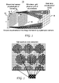
- FIGURE 1 depicts a simplified schematic view of prior-art plenoptic camera 10 comprised of an image sensor 12 in spaced relationship from a main lens 14.
- the image sensor 12 comprises a plurality of individual light sensing elements 16 arranged in an array of n 1 x n 2 where n 1 and n 2 are integers.
- Each of the light sensing elements of the image sensor 12 captures the light associated with a corresponding pixel in the image at the focal point of the main lens 14.
- the plenoptic camera 10 of FIG. 1 includes a micro-lens array 18 comprised of individual micro-lenses 20.
- the micro-lens array 18 lies in spaced between the image sensor 12 and the main lens 14. Depending on the nature of the plenoptic camera, the micro-lens array 18 will lie a focal length or longer from the image sensor 12.
- the micro-lenses 20 in the micro-lens array 18 have a hexagonal arrangement.
- a Bayer-pattern color filter (not shown) filters light incident on the individual light-sending elements of the camera image sensor, thereby enabling the image sensor 12 to capture color information in a roughly sampled image. This sampled image contains small sub-images formed under each micro-lens, as illustrated by FIG. 2 .
- FIGURE 3 depicts a pattern created by mosaicking the individual pixels of the sub-images of FIG. 2 .
- the resultant captured image can undergo de-mosaicking after de-multiplexing the views.
- the hexagonal arrangement of the micro-lenses 20 in the micro-lens array 18 of FIG. 1 yields in Bayer patterns that suffer from irregularity and severe monochromaticism, i.e., the color sampling of the scene suffers from big spatial gaps between the samples as seen in FIG. 3 .
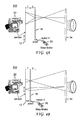
- FIGURES 4A and 4B depict schematic views of a plenoptic camera 100 in accordance with a particular and non specific embodiment of the present principles, which overcomes at least one of the aforementioned disadvantages of prior-art plenoptic cameras.
- the plenoptic camera 100 of FIGS. 4A and 4B like the plenoptic camera 10 of FIG. 1 , comprises an image sensor 12, a main lens 14, and a micro-lens array 18 spaced between the image sensor and main lens.
- the plenoptic camera 100 of FIGS. 4A and 4B has a moveable micro-lens array 18.
- the plenoptic camera 100 of the present principles includes a first prime mover 20 in the form of an electric motor that displaces the moveable micro-lens 18 array in synchronism manner with the camera's frame rate to obtain a multi-(spatial/angular/chromatic) resolution pyramid of the scene.
- the electric motor 20 can displace the micro-lens array 18 from a starting position 0 (pos0), depicted in FIG. 4A which lies a distance f +d from the image sensor 12, where f represents the focal plane of the micro lenses in the array 18 with highest f-number, to a position 1 (pos1) a distance f from the image sensor 12, as seen in FIG. 4B .
- the motor 20 affords the camera 100 of the present principles the ability to switch from a second type of plenoptic camera ("type 2") to a first type of plenoptic camera ("type 1").
- type 2 plenoptic camera having a frame rate of 56 fps, such as the Raytrix camera, the interval between successive frames equals 18 ms. Having the motor 20 move the micro-lens 18 during the period between frames assures substantially no image degradation due to motion blur.
- the image sensor 12 will capture a stack of images with a frame rate of 11.2 fps. This stack of images has interesting properties. Knowing the amount of displacement yields a stack that presents a pyramid of images having increasing spatial resolution and decreasing angular resolution. This pyramid of multi-resolution images provides rich chromatic information of a scene thanks to the fixed Bayer pattern on the image sensor 12. The image captured at pos1 of the micro-lens array 18 as depicted in FIG.
- the image of pos0 (the image of the state-of-art Raytrix camera configuration, that is a "type 2" plenoptic camera) will typically lie at the bottom of this pyramid and will have the highest spatial resolution and lowest angular resolution.
- Configuring the plenoptic camera 100 of the present principles with a moveable micro-lens 18 displaced by the electric motor 20 advantageously yields a hybrid plenoptic camera.
- the moveable micro-lens array 18 allows the camera 100 of the present principles to act as a combination of a "type 1" and "type 2" plenoptic camera, thus the advantages of each type of the existing plenoptic cameras.
- the configuration of the plenoptic camera 100 maximizes angular resolution, spatial resolution, chromatic resolution, and depth of field.
- the images captured by the plenoptic camera 100 of the present principles can undergo processing using one or more of several well-known image-processing approaches (e.g., ray tracing, or multi-frame super resolution algorithms to obtain a high spatial and angular resolution light field.
- image-processing approaches e.g., ray tracing, or multi-frame super resolution algorithms to obtain a high spatial and angular resolution light field.
- the plenoptic camera 100 of the present principles includes a hardware configuration inspired by the human visual system to simplify further the ill-posed de-mosaicking problem of existing plenoptic cameras.
- the fovea constitutes the only part of the eye that captures the color information.
- the Fovea contains randomly distributed cells, i.e., Long, Medium and Short wavelength cones that sample the color information, In other words, each cone captures light information of a certain wavelength at a certain spatial position on the fovea (which corresponds to a mosaicked image).
- the optical nerves transfer this information to the brain to obtain the color image of the scene.
- the plenoptic camera 100 of the present principles includes a second electric motor 22 that reciprocates moves the image sensor 12 parallel to the micro-lens array 18, thus effectively jiggling the image sensor back and forth in a direction orthogonal to movement of the micro-lens array.
- the displacement of the micro-lens array 18 is synchronized to the frame capture mechanism (not shown) of the plenoptic camera 100 so a displacement of one pixel results in displacement of the underlying image projected onto the image sensor 12 from the micro-lens array 18 by one pixel.
- This second image contains exactly the same information as the image captured when the micro-lens grid resided in its prior position, but the Bayer color pattern now changes to yield the complementary colors.
- the plenoptic camera 100 of the present principles can capture a first image at pos0 as depicted in FIG. 4A . Thereafter, the electric motor 22 can displace the image sensor 12 by a one pixel prior to obtaining another image by the image sensor at pos0, but with the different color channel information. The addition of the second electric motor 22 to displace the image sensor 12 increases the color resolution greatly and makes the difficult task of de-mosaicking a much easier one. Implementing this feature reduces the frame rate of the camera to 11 fps.
Landscapes
- Engineering & Computer Science (AREA)
- Multimedia (AREA)
- Signal Processing (AREA)
- Physics & Mathematics (AREA)
- General Physics & Mathematics (AREA)
- Optics & Photonics (AREA)
- Theoretical Computer Science (AREA)
- Computing Systems (AREA)
- Studio Devices (AREA)
- Color Television Image Signal Generators (AREA)
- Lens Barrels (AREA)
- Transforming Light Signals Into Electric Signals (AREA)
Priority Applications (9)
| Application Number | Priority Date | Filing Date | Title |
|---|---|---|---|
| EP14305870.9A EP2955913A1 (fr) | 2014-06-10 | 2014-06-10 | Caméra à fonction plenoptique hybride |
| CN201580030648.6A CN106464789A (zh) | 2014-06-10 | 2015-06-09 | 混合全光相机 |
| PCT/EP2015/062841 WO2015189211A1 (fr) | 2014-06-10 | 2015-06-09 | Appareil photo plénoptique hybride |
| JP2016571707A JP2017525188A (ja) | 2014-06-10 | 2015-06-09 | ハイブリッドプレノプティックカメラ |
| BR112016028742A BR112016028742A2 (pt) | 2014-06-10 | 2015-06-09 | câmera plenótica híbrida |
| EP15726216.3A EP3155806A1 (fr) | 2014-06-10 | 2015-06-09 | Appareil photo plénoptique hybride |
| US15/317,160 US10491792B2 (en) | 2014-06-10 | 2015-06-09 | Hybrid plenoptic camera |
| KR1020177000378A KR20170016940A (ko) | 2014-06-10 | 2015-06-09 | 하이브리드 플렌옵틱 카메라 |
| TW104118816A TW201603571A (zh) | 2014-06-10 | 2015-06-10 | 混合式全光相機 |
Applications Claiming Priority (1)
| Application Number | Priority Date | Filing Date | Title |
|---|---|---|---|
| EP14305870.9A EP2955913A1 (fr) | 2014-06-10 | 2014-06-10 | Caméra à fonction plenoptique hybride |
Publications (1)
| Publication Number | Publication Date |
|---|---|
| EP2955913A1 true EP2955913A1 (fr) | 2015-12-16 |
Family
ID=51059389
Family Applications (2)
| Application Number | Title | Priority Date | Filing Date |
|---|---|---|---|
| EP14305870.9A Withdrawn EP2955913A1 (fr) | 2014-06-10 | 2014-06-10 | Caméra à fonction plenoptique hybride |
| EP15726216.3A Ceased EP3155806A1 (fr) | 2014-06-10 | 2015-06-09 | Appareil photo plénoptique hybride |
Family Applications After (1)
| Application Number | Title | Priority Date | Filing Date |
|---|---|---|---|
| EP15726216.3A Ceased EP3155806A1 (fr) | 2014-06-10 | 2015-06-09 | Appareil photo plénoptique hybride |
Country Status (8)
| Country | Link |
|---|---|
| US (1) | US10491792B2 (fr) |
| EP (2) | EP2955913A1 (fr) |
| JP (1) | JP2017525188A (fr) |
| KR (1) | KR20170016940A (fr) |
| CN (1) | CN106464789A (fr) |
| BR (1) | BR112016028742A2 (fr) |
| TW (1) | TW201603571A (fr) |
| WO (1) | WO2015189211A1 (fr) |
Cited By (1)
| Publication number | Priority date | Publication date | Assignee | Title |
|---|---|---|---|---|
| FR3050833A1 (fr) * | 2016-04-27 | 2017-11-03 | Safran | Camera plenoptique avec correction d'aberrations geometriques |
Families Citing this family (6)
| Publication number | Priority date | Publication date | Assignee | Title |
|---|---|---|---|---|
| CN106231202A (zh) * | 2016-09-26 | 2016-12-14 | 胡晓明 | 全景多光谱全光影像采集方法及系统 |
| CN107613166B (zh) * | 2017-09-18 | 2019-11-01 | 丁志宇 | 光场相机及其安装参数确定方法、装置、存储介质 |
| CN110596885B (zh) * | 2019-09-17 | 2022-11-18 | 浙江荷湖科技有限公司 | 扫描光场成像系统 |
| CN111182238B (zh) * | 2019-11-15 | 2023-04-18 | 浙江荷湖科技有限公司 | 基于扫描光场的高分辨率移动电子设备的成像装置及方法 |
| KR20210124807A (ko) * | 2020-04-07 | 2021-10-15 | 에스케이하이닉스 주식회사 | 이미지 센싱 장치 |
| CN112235508B (zh) * | 2020-10-14 | 2021-10-29 | 浙江大学 | 一种聚焦型光场相机系统的参数设计方法 |
Citations (4)
| Publication number | Priority date | Publication date | Assignee | Title |
|---|---|---|---|---|
| US20050151861A1 (en) * | 2004-01-13 | 2005-07-14 | International Business Machines Corporation | Performance digital image sensing |
| WO2007092545A2 (fr) * | 2006-02-07 | 2007-08-16 | The Board Of Trustees Of The Leland Stanford Junior University | Agencements d'imagerie variable et méthodes associées |
| US20110149126A1 (en) * | 2009-12-22 | 2011-06-23 | Olympus Corporation | Multiband image pickup method and device |
| US8189089B1 (en) * | 2009-01-20 | 2012-05-29 | Adobe Systems Incorporated | Methods and apparatus for reducing plenoptic camera artifacts |
Family Cites Families (7)
| Publication number | Priority date | Publication date | Assignee | Title |
|---|---|---|---|---|
| JP4264569B2 (ja) * | 2007-01-09 | 2009-05-20 | ソニー株式会社 | 撮像装置 |
| US8289440B2 (en) * | 2008-12-08 | 2012-10-16 | Lytro, Inc. | Light field data acquisition devices, and methods of using and manufacturing same |
| JP5623356B2 (ja) * | 2011-08-29 | 2014-11-12 | キヤノン株式会社 | 撮像装置 |
| US8953012B2 (en) * | 2012-02-13 | 2015-02-10 | Raytheon Company | Multi-plenoptic system with image stacking and method for wide field-of-regard high-resolution imaging |
| CN104303493A (zh) * | 2012-05-09 | 2015-01-21 | 莱特洛公司 | 用于改进的光场捕获和操作的光学系统的优化 |
| US9179126B2 (en) | 2012-06-01 | 2015-11-03 | Ostendo Technologies, Inc. | Spatio-temporal light field cameras |
| CN203219391U (zh) | 2013-04-09 | 2013-09-25 | 上海海鸥数码照相机有限公司 | 可拍摄数码照片的光场相机 |
-
2014
- 2014-06-10 EP EP14305870.9A patent/EP2955913A1/fr not_active Withdrawn
-
2015
- 2015-06-09 EP EP15726216.3A patent/EP3155806A1/fr not_active Ceased
- 2015-06-09 CN CN201580030648.6A patent/CN106464789A/zh active Pending
- 2015-06-09 JP JP2016571707A patent/JP2017525188A/ja active Pending
- 2015-06-09 KR KR1020177000378A patent/KR20170016940A/ko unknown
- 2015-06-09 US US15/317,160 patent/US10491792B2/en active Active
- 2015-06-09 BR BR112016028742A patent/BR112016028742A2/pt active Search and Examination
- 2015-06-09 WO PCT/EP2015/062841 patent/WO2015189211A1/fr active Application Filing
- 2015-06-10 TW TW104118816A patent/TW201603571A/zh unknown
Patent Citations (4)
| Publication number | Priority date | Publication date | Assignee | Title |
|---|---|---|---|---|
| US20050151861A1 (en) * | 2004-01-13 | 2005-07-14 | International Business Machines Corporation | Performance digital image sensing |
| WO2007092545A2 (fr) * | 2006-02-07 | 2007-08-16 | The Board Of Trustees Of The Leland Stanford Junior University | Agencements d'imagerie variable et méthodes associées |
| US8189089B1 (en) * | 2009-01-20 | 2012-05-29 | Adobe Systems Incorporated | Methods and apparatus for reducing plenoptic camera artifacts |
| US20110149126A1 (en) * | 2009-12-22 | 2011-06-23 | Olympus Corporation | Multiband image pickup method and device |
Cited By (1)
| Publication number | Priority date | Publication date | Assignee | Title |
|---|---|---|---|---|
| FR3050833A1 (fr) * | 2016-04-27 | 2017-11-03 | Safran | Camera plenoptique avec correction d'aberrations geometriques |
Also Published As
| Publication number | Publication date |
|---|---|
| CN106464789A (zh) | 2017-02-22 |
| WO2015189211A1 (fr) | 2015-12-17 |
| US10491792B2 (en) | 2019-11-26 |
| US20170118387A1 (en) | 2017-04-27 |
| KR20170016940A (ko) | 2017-02-14 |
| BR112016028742A2 (pt) | 2017-08-22 |
| EP3155806A1 (fr) | 2017-04-19 |
| JP2017525188A (ja) | 2017-08-31 |
| TW201603571A (zh) | 2016-01-16 |
Similar Documents
| Publication | Publication Date | Title |
|---|---|---|
| US10491792B2 (en) | Hybrid plenoptic camera | |
| CN105744163B (zh) | 一种基于深度信息跟踪对焦的摄像机及摄像方法 | |
| CN103997599B (zh) | 图像处理设备、图像拾取设备以及图像处理方法 | |
| US9965834B2 (en) | Image processing apparatus and image acquisition apparatus | |
| US8749694B2 (en) | Methods and apparatus for rendering focused plenoptic camera data using super-resolved demosaicing | |
| JP6347675B2 (ja) | 画像処理装置、撮像装置、画像処理方法、撮像方法及びプログラム | |
| CN103688536B (zh) | 图像处理装置、图像处理方法 | |
| CN104662887B (zh) | 图像处理设备、图像处理方法和具有该图像处理设备的摄像设备 | |
| CN107079087A (zh) | 摄像装置及对象物识别方法 | |
| TW201622403A (zh) | 數位重對焦方法 | |
| WO2013032769A1 (fr) | Production de vidéos mises au point, à partir d'une seule vidéo capturée | |
| JP2014057181A (ja) | 画像処理装置、撮像装置、画像処理方法、および、画像処理プログラム | |
| KR101689534B1 (ko) | 멀티스케일 이미징 시스템 | |
| CN108805921B (zh) | 图像获取系统及方法 | |
| JP5979134B2 (ja) | 画像処理装置および画像処理プログラム | |
| CN109302600B (zh) | 一种立体场景拍摄装置 | |
| JP2016111678A (ja) | 撮像素子、撮像装置、焦点検出装置ならびに画像処理装置およびその制御方法 | |
| CN110995982A (zh) | 图像处理装置及其控制方法、摄像装置、以及记录介质 | |
| CN103503447B (zh) | 拍摄装置及拍摄装置的控制方法 | |
| EP3104604A1 (fr) | Dispositif d'imagerie à champ lumineux | |
| JP6006506B2 (ja) | 画像処理装置及び画像処理方法、プログラム、並びに記憶媒体 | |
| JP2014049895A (ja) | 画像処理方法 | |
| JP6439285B2 (ja) | 画像処理装置、撮像装置および画像処理プログラム | |
| KR20140045636A (ko) | 레이어드 파노라마 영상 생성 장치 | |
| JP6817855B2 (ja) | 画像処理装置、撮像装置、画像処理方法、及びプログラム |
Legal Events
| Date | Code | Title | Description |
|---|---|---|---|
| PUAI | Public reference made under article 153(3) epc to a published international application that has entered the european phase |
Free format text: ORIGINAL CODE: 0009012 |
|
| AK | Designated contracting states |
Kind code of ref document: A1 Designated state(s): AL AT BE BG CH CY CZ DE DK EE ES FI FR GB GR HR HU IE IS IT LI LT LU LV MC MK MT NL NO PL PT RO RS SE SI SK SM TR |
|
| AX | Request for extension of the european patent |
Extension state: BA ME |
|
| STAA | Information on the status of an ep patent application or granted ep patent |
Free format text: STATUS: THE APPLICATION IS DEEMED TO BE WITHDRAWN |
|
| 18D | Application deemed to be withdrawn |
Effective date: 20160617 |