EP2955539A1 - Distance measuring device - Google Patents
Distance measuring device Download PDFInfo
- Publication number
- EP2955539A1 EP2955539A1 EP14172114.2A EP14172114A EP2955539A1 EP 2955539 A1 EP2955539 A1 EP 2955539A1 EP 14172114 A EP14172114 A EP 14172114A EP 2955539 A1 EP2955539 A1 EP 2955539A1
- Authority
- EP
- European Patent Office
- Prior art keywords
- light
- determining
- current
- time
- pulse
- Prior art date
- Legal status (The legal status is an assumption and is not a legal conclusion. Google has not performed a legal analysis and makes no representation as to the accuracy of the status listed.)
- Granted
Links
Images


Classifications
-
- G—PHYSICS
- G01—MEASURING; TESTING
- G01S—RADIO DIRECTION-FINDING; RADIO NAVIGATION; DETERMINING DISTANCE OR VELOCITY BY USE OF RADIO WAVES; LOCATING OR PRESENCE-DETECTING BY USE OF THE REFLECTION OR RERADIATION OF RADIO WAVES; ANALOGOUS ARRANGEMENTS USING OTHER WAVES
- G01S17/00—Systems using the reflection or reradiation of electromagnetic waves other than radio waves, e.g. lidar systems
- G01S17/02—Systems using the reflection of electromagnetic waves other than radio waves
- G01S17/06—Systems determining position data of a target
- G01S17/08—Systems determining position data of a target for measuring distance only
-
- G—PHYSICS
- G01—MEASURING; TESTING
- G01S—RADIO DIRECTION-FINDING; RADIO NAVIGATION; DETERMINING DISTANCE OR VELOCITY BY USE OF RADIO WAVES; LOCATING OR PRESENCE-DETECTING BY USE OF THE REFLECTION OR RERADIATION OF RADIO WAVES; ANALOGOUS ARRANGEMENTS USING OTHER WAVES
- G01S7/00—Details of systems according to groups G01S13/00, G01S15/00, G01S17/00
- G01S7/48—Details of systems according to groups G01S13/00, G01S15/00, G01S17/00 of systems according to group G01S17/00
- G01S7/483—Details of pulse systems
- G01S7/486—Receivers
- G01S7/4865—Time delay measurement, e.g. time-of-flight measurement, time of arrival measurement or determining the exact position of a peak
-
- G—PHYSICS
- G01—MEASURING; TESTING
- G01S—RADIO DIRECTION-FINDING; RADIO NAVIGATION; DETERMINING DISTANCE OR VELOCITY BY USE OF RADIO WAVES; LOCATING OR PRESENCE-DETECTING BY USE OF THE REFLECTION OR RERADIATION OF RADIO WAVES; ANALOGOUS ARRANGEMENTS USING OTHER WAVES
- G01S17/00—Systems using the reflection or reradiation of electromagnetic waves other than radio waves, e.g. lidar systems
- G01S17/02—Systems using the reflection of electromagnetic waves other than radio waves
- G01S17/06—Systems determining position data of a target
- G01S17/08—Systems determining position data of a target for measuring distance only
- G01S17/10—Systems determining position data of a target for measuring distance only using transmission of interrupted, pulse-modulated waves
-
- G—PHYSICS
- G01—MEASURING; TESTING
- G01S—RADIO DIRECTION-FINDING; RADIO NAVIGATION; DETERMINING DISTANCE OR VELOCITY BY USE OF RADIO WAVES; LOCATING OR PRESENCE-DETECTING BY USE OF THE REFLECTION OR RERADIATION OF RADIO WAVES; ANALOGOUS ARRANGEMENTS USING OTHER WAVES
- G01S7/00—Details of systems according to groups G01S13/00, G01S15/00, G01S17/00
- G01S7/48—Details of systems according to groups G01S13/00, G01S15/00, G01S17/00 of systems according to group G01S17/00
- G01S7/483—Details of pulse systems
- G01S7/484—Transmitters
-
- G—PHYSICS
- G01—MEASURING; TESTING
- G01S—RADIO DIRECTION-FINDING; RADIO NAVIGATION; DETERMINING DISTANCE OR VELOCITY BY USE OF RADIO WAVES; LOCATING OR PRESENCE-DETECTING BY USE OF THE REFLECTION OR RERADIATION OF RADIO WAVES; ANALOGOUS ARRANGEMENTS USING OTHER WAVES
- G01S7/00—Details of systems according to groups G01S13/00, G01S15/00, G01S17/00
- G01S7/48—Details of systems according to groups G01S13/00, G01S15/00, G01S17/00 of systems according to group G01S17/00
- G01S7/497—Means for monitoring or calibrating
-
- G—PHYSICS
- G01—MEASURING; TESTING
- G01S—RADIO DIRECTION-FINDING; RADIO NAVIGATION; DETERMINING DISTANCE OR VELOCITY BY USE OF RADIO WAVES; LOCATING OR PRESENCE-DETECTING BY USE OF THE REFLECTION OR RERADIATION OF RADIO WAVES; ANALOGOUS ARRANGEMENTS USING OTHER WAVES
- G01S17/00—Systems using the reflection or reradiation of electromagnetic waves other than radio waves, e.g. lidar systems
- G01S17/88—Lidar systems specially adapted for specific applications
- G01S17/89—Lidar systems specially adapted for specific applications for mapping or imaging
- G01S17/894—Three-dimensional [3D] imaging with simultaneous measurement of time-of-flight at a two-dimensional [2D] array of receiver pixels, e.g. time-of-flight cameras or flash lidar
Definitions
- This invention relates to a distance measuring device determining a distance of an object from the distance measuring device and its associated method for doing the same.
- One method of distance measuring devices is the measurement of the distance to an object by determining the time of flight of a light pulse. It is known in the art to provide distance measuring devices which send a precisely timed light pulse toward an object and to make gated measurements of the light reflected thereby.
- a distance measuring device sends a light pulse toward an object and records the reflected light from the object by a light sensor (typically which converts the incident light to voltage/current) using two gated time intervals equal of time.
- the light pulse emitted from a light source is typically driven by a pulse generator providing a digital pulse.
- a first gated time interval is typically synchronized with the digital pulse such that it starts at the same time the digital pulse starts and another gated time interval starting at the end of the digital pulse.
- the durations of both gated time intervals are generally set to be equal to the length of the digital pulse.
- the range of the object is in one type of method is determined by the ratio between the amount of reflected light received during the first gated time interval and the sum of the two amounts of reflected light received respectively during the first gated time interval and the second gated time interval.
- the existing distance measuring devices are not enough accurate for security applications such as safety functions of automotive applications. Synchronization of digital pulses generates error. Furthermore the pulse length variation and delays are introduced which vary with environmental parameters such as supply voltage, temperature, or variation in electronic component parameters (which drift from their nominal values) Solutions as calibration table stored in memory of a distance measuring device exist. However, those solutions do not fully compensate the existing variations. Those solutions cost time, effort and money for implementation.
- a method for determining the distance d from a unit to an object comprising:
- a method for determining the distance d from a unit to an object may comprise:
- the measure of the intensity of reflected light may be current Ipd through the light sensor.
- the thresholds THL1 and THL2 may be equal.
- an apparatus for determining the distance d from a unit to an object comprises:
- the thresholds THL1 and THL2 may be equal.
- the means of measuring the intensity of reflected light may comprise means to measure current Ipd through the light sensor.
- the means for determining the point T0 and for determining the point T1 may comprise a voltage comparator having an adjustable threshold voltage input.
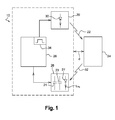
- FIG. 1 is a block diagram of a prior art distance measuring device 10.
- the device 10 determines a distance d from an object 24 from the device 10.
- the device 10 includes a light driver 20 having an optical diode 30 such as a laser diode able to generate an light pulse 22, towards the object 24 whose distance d is to be measured, and a controller 28 having a connection with the light driver 20 for providing control of the light driver 20 by way of a digital pulse.
- the device 10 further includes a light sensor 26, connected to the controller 28, able to detect a received light pulse 32 generated by the reflection of the emitted light pulse 22 by the object 24, and converts into a current/voltage pulse.
- a signal generator 34 which is located in the controller 28 and managed by the controller 28, controls generation of the digital pulse that is sent to the light driver 20 so that the length ⁇ Td of the digital pulse sent to the emitter is known by the controller 28.
- the light sensor 26 includes a photosensitive element 27 such as a photo diode which produces an electrical current Iph as a function of (intensity of) the reflected light pulse 32 and a current integrator which is connected to the photosensitive element 27 and converts the current Iph to an electrical charge.
- the output of the charge integrator is connected to the controller 28 via multiplexer internal of the photosensitive element.
- the light sensor can further includes a first and a second capacitors 21, 23 which terminals are the integrator's output. Functions of the light sensor 26 will be explained in details through the description of figure 2 .
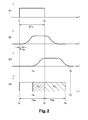
- FIG. 1 shows timing charts of signals processed by the prior art distance measuring device 10.
- a first timing chart A1 shows amplitude of the digital pulse that is sent to the light driver 20 by the signal generator 34 of the controller 28. It is characterized by its length ⁇ Td known by the controller 28 between its rising edge and its falling edge. The rising edge occurs at a first time Tr and the falling edge occurs at a second time Tf.
- a second timing chart A2 shows the amplitude of emitted light pulse 22 according to the setting of the prior art distance measuring device 10.
- the controller 28 has no information about the emitted light pulse 22 as there is no feedback information from the light driver 20 to the controller 28.
- the time delay ⁇ Tde is partially due to inherent hardware characteristics of the light driver 20.
- a third timing chart A3 shows the amplitude of light pulse 32 reflected by the object 24 and received by the light sensor 26.
- the light sensor 26 starts to receive the reflected light pulse 32.
- the light sensor 26 ends to receive the reflected pulse 32.
- a fourth timing chart A4 shows a first and a second time slots TSa, TSb.
- the 'Y' axis is a representation of the activation of the time slots (TSa, TSb).
- the first and the second time slots TSa, TSb are under the control of the controller 28, such that the light sensor 26 registers the current Iph through the light sensor 26 e.g. by integrating the current Iph during these time slots so as to get a measure of aggregate light falling on the light sensor 26 in these time slot periods.
- the duration of the first and the second time slot TSa, TSb is set equal to the length ⁇ Td of the digital pulse.
- the first time slot TSa starts at a time Tr the controller 28 initiates the digital pulse for the light sensor 26 and ends at a time Tf the controller 28 stops the digital pulse i.e. at the end of the digital pulse.
- the second time slot TSb starts at the time Tf and ends at a time Te such that the duration of the second time slot Tsb is equal of the duration of the first time slot TSa.
- the photosensitive element 27 starts to generate the current Iph at the time Ta and ends to generate it at the time Te i.e. the reflected light pulse 32 starts to influence the photosensitive element 27 at the time Ta and stops at the time Tb.
- the current Iph is integrated only during the first and a second adjacent time slots TSa, TSb of equal time that results respectively to a first and a second amount of electrical charges Qa, Qb.
- the first capacitor 21 is connected with the photosensitive element 27 only during the first time slot TSa such that it charges by the current Ipd from the time Ta until the time Tf.
- the charge of the first capacitor 21 results in the first amount of electrical charge Qa stored on it.
- the second capacitor 23 is connected with the photosensitive element 27 only during the second time slot TSb such that it charges by the current Iph from the time Tf until the time Te.
- the charge of the second capacitor 23 results in the second amount of electrical charge Qb stored on it.
- the first and the second amounts of electrical charges Qa, Qb can be acquired through the terminals of the first and the second capacitors 21, 23, in such a case the terminals constitute a first and a second integrator's output voltages value Va, Vb, those voltages output being simply dependent on the capacitors value.
- the prior art distance measuring device 10 uses digital parameters for the distance d determination as the length of the digital pulse and its starting time. These digital parameters do not accurately represent what is really emitted in the air, because of the temperature dependency of the hardware, of the length of the emitted light pulse and of the time delay ⁇ Tde. Following description relative to the invention provides an example of an improved distance measuring device.
- FIG. 3 is a block diagram example of a distance measuring device 50 according to one aspect of the invention.
- the distance measuring device 50 determines the distance d of the object 24 from the distance measuring device 50.
- the distance measuring device 50 includes light driver 60 having another optical diode 70 such as another laser diode able to generate another emitted light pulse 62 towards the object 24 whose distance d is to be measured, controller 68 having another connection with the light driver 60 for providing it a digital pulse, and the light sensor 26, having its integrator output connected to the controller 68, able to detect another received light pulse 72 generated by the reflection of the other emitted light pulse 62 by the object 24.
- a signal generator 84 which is located in the controller 68 and managed by the controller 68, controls generation of the digital pulse that is sent to the light driver 60.
- the signal generator 84 can be located externally to the controller 68.
- the controller 68 can be an integrated circuit such as a Field Programmable Gate Array (FPGA).
- FPGA Field Programmable Gate Array
- the light driver 60 While receiving the digital pulse from the signal generator 84, the light driver 60 biases its optical diode 70 for duration equal to the length of the digital pulse. A current I1 consequently flows through the optical diode 70 and thus the emitted light pulse 62 emitted from the optical diode 70 is sent toward the object 24.
- the light driver 60 informs the controller 68 on the level of the emitted light pulse 62 by a wired connection such that the controller 68 is able to assess the level of the emitted light pulse 62.
- the current I1 flowing through the optical diode 70 flows through a resistor R connected in series with the optical diode 70, such that the voltage over the resistor R, which is proportional to the current I1, can be determined by the controller 68 via a wire connection.
- the light sensor 26 may be used to detect the level of the emitted light pulse 62.
- the distance measuring device 50 further includes a first voltage comparator 80, which is located in the controller 68, having two inputs, one input being set to a reference level THL1 such as a first adjustable threshold voltage, the second input being connected to the light driver 60 such that the level of the current I1 of the optical diode 70 can be compared with the first adjustable threshold voltage.
- the first voltage comparator 80 further includes an output that switches its logic state in function of the level of the current I1 compared with the first adjustable threshold voltage. In an example, in order to implement this, the current I1 flowing through the optical diode 70 flows through the resistor R connected in series with the optical diode 70, such that the voltage over the resistor R, which is proportional to the current I1, can be effectively compared with the first adjustable threshold voltage.
- the first voltage comparator 80 can thus provide to the controller the information on the presence of the rising edge of the emitted light pulse 62 if the current I1 provides a voltage over the resistor R exceeding the first adjustable threshold voltage value THL1 during the rising edge of the emitted light pulse 62.
- the first voltage comparator 80 can further provide to the controller the information on the falling edge of the emitted light pulse 62 if the current I1 provides a voltage over the resistor R smaller than the first adjustable threshold voltage value THL1 during the falling edge of the emitted light pulse 62.
- the first voltage comparator 80 can be located externally to the controller 68, as a stand-alone first voltage comparator 80, or integrated in a device as in the light driver 60.
- the distance measuring device 50 can comprise other methods so the first voltage comparator 80 can monitor the level of the emitted light pulse 62.
- the level of the emitted light pulse 62 can be compared to another reference THL1 than a threshold voltage by other means than the first voltage comparator 80.
- Well known solution can be for instance the usage of a current comparator using current mirrors.
- the light sensor 26 includes the photosensitive element 27 such as a photo diode which produces an electrical current Ipd as a function of the reflected light pulse 72 and a current integrator which is connected to the photosensitive element 27 and converts (e.g. sums/integrates) the current Ipd to an electrical charge.
- the output of the charge integrator is connected to the controller 68. Functions of the light sensor 26 will be explained in details through the description of figure 5 .
- the light sensor 26 is further comprises a second voltage comparator 82 capable of comparing the intensity of the reflected light pulse 72 with a second reference level.
- the intensity may dictate the current Ipd through the photosensitive element 27.
- the voltage across the photosensitive element 27 is proportion to said generated current Ipd and thus provides a voltage to be compared with a second adjustable threshold voltage, the output of the second voltage comparator 82 being connected with the controller 68.
- the second voltage comparator 82 can provide to the controller 68 the information on the presence of the rising edge of the reflected light pulse 72 when the level of the reflected light pulse 72 exceeds the second adjustable threshold voltage value THL2.
- the second voltage comparator 82 can further provide to the controller 68 the information on the falling edge of the reflected light pulse 72 when the level of the reflected light pulse 72 is smaller than the second adjustable threshold voltage value THL2.
- the second voltage comparator 82 can be located externally to the light sensor 26, as a stand-alone second voltage comparator, or integrated in a device as in the controller 68. Functions of the option of the light sensor 26 will be explained in detail later with reference to figure 5 .
- the distance measuring device 50 can comprise other solution than the second voltage comparator 82 to monitor the level of the reflected light pulse 72.
- the level of the reflected light pulse 72 can be compared to another reference level than a threshold voltage by other means than the second voltage comparator 82.
- Well known solution can be for instance the usage of a current comparator using current mirrors.
- the distance measuring device 50 further includes an analog Dual Slope Time to Digital Converter 71 (DSTDC).
- DSTDC 71 including a first and a second capacitors 73, 75, two electronic switches 74, 76, controlled by the controller 68, a current source 79 and a third voltage comparator 78, communicates with the controller 68 and provides the charging level of at least one of the first and the second capacitors 73, 75 to the controller 68 via an Analog to Digital Converter 86. Details are explained in more detail hereafter.
- FIG. 4 shows an example of a simplified schematic diagram of the Dual Slope Time to Digital Converter 71.
- the constant current Ic from current source 79 is provided to two paths. Each path includes one of the two electronic switches 74, 76, controlled by the controller 68 connecting the current source to one of the first and the second capacitors 73, 75.
- Each of the first and the second capacitor 73, 75 is connected to one of the two inputs of the third voltage comparator 78 such that the charge level of the first capacitor 73 can be compared to the charge level of the second capacitor 75.
- the output of the third voltage comparator 78 is connected to the controller 68.
- the first capacitor 73 is connected to the Analog to Digital Converter 86 located in the controller 68.
- the Analog to Digital Converter 86 is able to provide a voltage value of the first capacitor 73 to the controller 68.
- the Analog to Digital converter 86 can be located externally to the controller 68 as a stand-alone Analog to Digital Converter or integrated in the DSTDC 71.
- Figure 5 shows an example of timing charts of signals processed by the distance measuring device 50 according to one implementation of the methodology.
- a first timing chart B 1 shows the characteristics of the emitted light pulse 62 and specifically shows the current I1 flowing through the optical diode 70 during the emission of the emitted light pulse 62.
- the form of the current I1 includes a smooth rising edge RE and a smooth falling edge FE.
- the smooth rising edge RE corresponds to the transient during activation of the gate driver of the light driver 60, excited by the sharp rising edge of the digital pulse generated by the signal generator 84.
- the smooth falling edge FE corresponds to the transient during deactivation of the gate driver of the light driver 60 excited by the sharp falling edge of the digital pulse generated by the signal generator 84.
- a reference time T0 is shown when the level of the current I1 of the optical diode 70 exceeds a first level, e.g. when the current I1 produces a voltage that exceeds a first adjustable threshold voltage THL1.
- a time T1 is shown when the level of the current I1 becomes smaller than the first adjustable threshold THL1.
- the controller 68 is informed by the state of the output of the first voltage comparator 80 of the reference time T0 and T1.
- the first adjustable threshold voltage THL1 can be adjusted at a threshold value permitting the detection of the height of the emitted light pulse 62 having amplitude greater than the amplitude of the ambient light of the medium through which it propagates.
- a second timing chart B2 shows the voltage Vc of the first and the second capacitors 73, 75 of the DSTDC 71 during charging of the capacitors 73, 75 by the constant current Ic.
- the first capacitor 73 is charged by the constant current Ic of the current source 79.
- the time duration ⁇ T1 of the first time interval [TO, T1] is considered as an accurate value of the length of the emitted light pulse 62.
- the length of the emitted light pulse 62 determined from the charge of the first capacitor 71 performs between two events defined as the level of current I1 exceeding a first reference level THL1 and the level of the current I1 becoming smaller than the first reference level THL1.
- the length of the emitted light pulse would have been determined by a cumulative quantifiable number of digital clock cycles between the two identified events.
- the controller 68 activates the closure of the second switch 76 of the DSTDC 71 enabling the charging of the second capacitor 75 by the constant current Ic.
- the third voltage comparator 78 detects that the voltage value of the second capacitor 75 charged by the constant current Ic exceeds the voltage value VC1 stored on the first capacitor 73, the logic state of the output of the third voltage comparator 78 switches from its previous logic state to the logic state so that the controller 68 identifies a time T2 as illustrated.
- the controller 68 activates the opening of the second switch 76 of the DSTDC 71 stopping the charge of the second capacitor 75 by the constant current Ic.
- the second capacitor 75 charged by the constant current Ic of the current source 79 is accumulating electrical charges that provides a second value Qn of the cumulative metric as a second voltage value VC2 so that the voltage value VC2 stored on the second capacitor 75 is considered as equal to the voltage value VC1 stored on the first capacitor 73.
- the value C2 of the second capacitor 75 being equal to the value C1 of the first capacitor 73 and the voltage value VC2 across the second capacitor 75 being considered as equal to the voltage value VC1 stored on the first capacitor 73, the duration ⁇ T2 of the second time interval [T1-T2] becomes equal to the duration ⁇ T1 of the first time interval [TO- T1].
- a third timing chart B3 shows the characteristics of the reflected light pulse 72 and specifically shows the current Ipd provided through the light sensor 26 during the reception of the reflected light pulse 72.
- the form of the current Ipd includes a smooth rising edge RE2 and a smooth falling edge FE2.
- the level of the current Ipd through the light sensor 26 exceeds a second level, e.g. when the current Ipd produces a voltage that exceeds a second adjustable threshold voltage THL2 .
- a time TB is shown when the level of the current Ipd of the light sensor 26 becomes smaller than the second adjustable threshold voltage THL2.
- the controller 68 is informed by the second voltage comparator 82 of when voltage produced by the current achieves the second threshold voltage THL2 such that the controller 68 is able to identify the time TA and TB.
- the light sensor 26 starts to receive the reflected light pulse 72.
- the light sensor 26 ends to receive the reflected pulse 72.
- a fourth timing chart B4 shows a first and a second time slots TS1 and TS2.
- the 'Y' axis is a representation of the activation of the time slots (TS1, TS2).
- the first and the second time slots TS1, TS2 are under the control of the controller 28, such that the light sensor 26 is effectively enable by the controller 28 only during the time slots TS1, TS2 to register the current Ipd through the light sensor 26 e.g. by integrating the current Ipd during these time slots TS1, TS2 so as to get a measure of aggregate light falling on the light sensor 26 in these time slot periods.
- the duration of the first time slot TS1 is equal to the duration ⁇ T1 of the first time interval [T0-T1].
- the duration of the second time slot TS2 is equal to the duration ⁇ T2 of the second time interval [T1-T2]. As stated above, both time intervals duration are equal to the length of the emitted light pulse 62.
- the first time slot TS1 starts at the reference time T0.
- the second time slot TS2 starts at the time T1.
- the photosensitive element 27 starts to generate the current Ipd at the time T3 and ends to generate the current Ipd at the time T4, i.e. the received light pulse 72 starts to influence the photosensitive element 27 at the time T3 and stops at the time T4.
- the current Ipd is integrated during the first and a second adjacent time slots TS1, TS2 of equal time that results respectively to a first and a second amount of electrical charges Q1, Q2.
- the first capacitor 21 is connected with the photosensitive element 27 only during the first time slot TS 1 such that it charges by the current Ipd from the time T3 until the time T1.
- the charge of the first capacitor 21 results in the first amount of electrical charge Q1 stored on it.
- the second capacitor 23 is connected with the photosensitive element 27 only during the second time slot TS2 such that it charges by the current Ipd from the time T1 until the time T4.
- the charge of the second capacitor 23 results in the second amount of electrical charge Q2 stored on it.
- the first and the second amounts of electrical charges Q1, Q2 can be acquired through the terminals of the first and the second capacitors 21, 23, in such a case the terminals constitute a first and a second integrator's output voltages value V1, V2, those voltages output being simply dependent on the value of the first and the second capacitors 21, 23.
- a fifth timing chart B5 shows an alternative method.
- the 'Y' axis is a representation of the activation of the time slots (TS1, TS2).
- the method integrates the current Ipd starting at the time TA that depends on the point the second adjustable threshold voltage THL2 is achieved and ends at the time TB.
- the photosensitive element 27 starts to generate the current Ipd at the time TA and ends to generate the current Ipd at the time TB, i.e. the received light pulse 72 starts to influence the photosensitive element 27 at the time TA and stops at the time TB.
- the current Ipd is integrated during the first and the second time slots TS1, TS2 that results respectively to a third and a fourth amount of electrical charges Q3, Q4.
- the first capacitor 21 is connected with the photosensitive element 27 only from time TA until time T1 such that it charges by the current Ipd.
- the charge of the first capacitor 21 results in the third amount of electrical charge Q3 stored on it.
- the second capacitor 23 is connected with the photosensitive element 27 only from time T1 until time TB such that it charges by the current Ipd.
- the charge of the second capacitor 23 results in the second amount of electrical charge Q2 stored on it.
- the third and the fourth amounts of electrical charges Q3, Q4 can be acquired through the terminals of the first and the second capacitors 21, 23, in such a case the terminals constitute a third and a fourth integrator's output voltages value V3, V4, those voltages output being simply dependent on the value of the first and the second capacitor 21, 23.
- This alternative option wherein for instance the second threshold voltage THL2 is set at threshold value greater than the amplitude of another current of the light sensor 26 induced by the ambient light, provides the advantage of refining the estimation of the distance d of the object 24 as the third integrator's output voltage V3 and the fourth integrator's output voltage V4 do not include part of the amount of charges that could have been accumulated by the first and the second capacitors 21, 23 charged by the other current of the light sensor 26 induced by the ambient light.
Landscapes
- Engineering & Computer Science (AREA)
- Physics & Mathematics (AREA)
- Computer Networks & Wireless Communication (AREA)
- General Physics & Mathematics (AREA)
- Radar, Positioning & Navigation (AREA)
- Remote Sensing (AREA)
- Electromagnetism (AREA)
- Optical Radar Systems And Details Thereof (AREA)
- Measurement Of Optical Distance (AREA)
Abstract
Description
- This invention relates to a distance measuring device determining a distance of an object from the distance measuring device and its associated method for doing the same.
- One method of distance measuring devices is the measurement of the distance to an object by determining the time of flight of a light pulse. It is known in the art to provide distance measuring devices which send a precisely timed light pulse toward an object and to make gated measurements of the light reflected thereby. The time of flight of the light pulse is simply related to the range of the object through the relation d = c x Δtd / 2, where d is the distance to the object, c stands for the velocity of light in the medium through which it propagates and Δtd is the time delay between the pulse emission and its detection.
- Several distance measuring devices that include time-gated detection schemes are known in the art. As a well-known solution, a distance measuring device sends a light pulse toward an object and records the reflected light from the object by a light sensor (typically which converts the incident light to voltage/current) using two gated time intervals equal of time. The light pulse emitted from a light source is typically driven by a pulse generator providing a digital pulse. A first gated time interval is typically synchronized with the digital pulse such that it starts at the same time the digital pulse starts and another gated time interval starting at the end of the digital pulse. The durations of both gated time intervals are generally set to be equal to the length of the digital pulse. The range of the object is in one type of method is determined by the ratio between the amount of reflected light received during the first gated time interval and the sum of the two amounts of reflected light received respectively during the first gated time interval and the second gated time interval.
- The existing distance measuring devices are not enough accurate for security applications such as safety functions of automotive applications. Synchronization of digital pulses generates error. Furthermore the pulse length variation and delays are introduced which vary with environmental parameters such as supply voltage, temperature, or variation in electronic component parameters (which drift from their nominal values) Solutions as calibration table stored in memory of a distance measuring device exist. However, those solutions do not fully compensate the existing variations. Those solutions cost time, effort and money for implementation.
- It is an object of the invention to provide an improved distance measuring device and associated method for doing the same in order to overcome such problems. It is an object of the invention to determine accurately the distance of an object by determining accurately the length of an emitted light pulse and its starting time.
- In one aspect is provided a method for determining the distance d from a unit to an object comprising:
- sending a pulse of light from a light emitting component to said object by means of passing a current pulse I1 sent through said component; measuring the current I1 through or voltage across said light emitting component and determining the point T0 when this values achieves a pre-determined first threshold value THL1 and determining the
point T 1 when this values is reduced to a pre-determined second threshold value THL2; using the time point T1 to define two time windows; receiving a reflected pulse of light from said object at said unit by a light sensor; integrating a measure of the intensity of reflected light in said light sensor during the two time windows to provide two values (Q1/Q3 and Q2/Q4); and determining the time of flight from the values), the difference between T0 and T1 (T1-T0) and the speed of light, c. - In a preferred embodiment, a method for determining the distance d from a unit to an object may comprise:
- a step of sending a pulse of light from a light emitting component to said object by means of passing a current pulse I1 sent through said component; a step of measuring the current I1 through or voltage across said light emitting component and determining the point T0 when this values achieves a pre-determined first threshold value THL1 and determining the point T1 when this values is reduced to a pre-determined second threshold value THL2; a step of receiving a reflected pulse of light from said object at said unit by a light sensor; a step of integrating a measure of the intensity of reflected light in said light sensor between time T0 and T1 to provide a value Q1; a step of integrating a measure of the intensity of reflected light in said light sensor between time T1 and T2, where T2 is the time point equal to T0+(2*(T1-T0)),to provide a value Q2; a step of determining the distance d from the formula d = ½ x c x (T1-T0) x (Q1 /(Q1+Q2)).
- In another preferred embodiment a method for determining a distance d from a unit to an object may comprise:
- a step of sending a pulse of light from a light emitting component to said object by means of passing a current pulse I1 sent through said component; a step of measuring the current I1 through or voltage across said light emitting component and determining the point T0 when this value achieves a pre-determined first threshold value THL1 and determining the point T1 when this value is reduced to a pre-determined second threshold value THL2; a step of receiving a reflected pulse of light from said object at said unit by a light sensor; a step of measuring the current Ipd through or voltage across said light sensor and determining the point TA when this value achieves a pre-determined third threshold value THL3 and determining the point TB when this value is reduced to a pre-determined fourth threshold value THL4; a step of integrating a measure of the intensity of reflected light in said light sensor between time TA and T1 to provide a value Q3;
- a step of integrating a measure of the intensity of reflected light in said light sensor between time T1 and TB to provide a value Q4; a step of determining the distance d from the formula d = ½ x c x (T1-T0) x (Q3/(Q3+Q4)).
- The measure of the intensity of reflected light may be current Ipd through the light sensor.
- The value of (T1-T0) may be determined by charging a first capacitor of value C1 by a constant current Ic between times T0 and T1 to a voltage value VC1 and where T1-T0 = (VC1 x C1)/Ic.
- The thresholds THL1 and THL2 may be equal.
- In another embodiment, an apparatus for determining the distance d from a unit to an object is provided; the apparatus comprises:
- means to send a pulse of light from a light emitting component to said object by passing a current pulse I1 through said component; means to measure the current I1 through or voltage across said light emitting component and to determine the point T0 when this value achieves a pre-determined first threshold value THL1 and determining the point T1 when this value is reduced to a pre-determined second threshold value THL2; means to using the time point T1 to define two time windows; means to receive a reflected pulse of light from said object at said unit by a light sensor; means to integrate a measure of the intensity of reflected light in said light sensor during the two time windows to provide two values (Q1/Q3 and Q2/Q4); means to determine the time of flight from the two values (Q1/Q3 and Q2/Q4), the difference between T0 and T1 (T1-T0) and the speed of light, c.
- In another preferred embodiment an apparatus for determining the distance from the unit to an object may further comprise:
- means for sending a pulse of light from a light emitting component to said object by means of passing a current pulse I1 sent through said component; means for measuring the current I1 through or voltage across said light emitting component;
- means for determining the point T0 when the values of said current I1 achieves a pre-determined first threshold value THL1 and means for determining the point T1 when this values is reduced to a pre-determined second threshold value THL2; means for determining the point T2 where T2 is the time point equal to T0+(2*(T1-T0)); means for receiving a reflected pulse; means for integrating a measure of the intensity of reflected light in said light sensor between time T0 and T1 to provide a value Q1 and for integrating a measure of the intensity of reflected light in said light sensor between time T1 and T2, where T2 is the time point equal to T0 + (2*(T1-T0)), to provide a value Q2; means for determining the distance d from the formula d = ½ x c x (T1-T0) x (Q1/(Q1+Q2)).
- In another preferred embodiment an apparatus for determining the distance d from the unit to an object may further comprise:
- means for sending a pulse of light from a light emitting component to said object by means of passing a current pulse I1 sent through said component; means for measuring the current I1 through or voltage across said light emitting component and determining the point T0 when the values of said current I1 achieves a pre-determined first threshold value THL1 and means for determining the point T1 when this values is reduced to a pre-determined second threshold value THL2; light sensor means for receiving the reflected pulse of light from said object;
- means for measuring the current Ipd through or voltage across said light sensor means and means for determining the point TA when the values of said current Ipd through the light sensor achieves a pre-determined third threshold value THL3 and means for determining the point TB when the values of said current is reduced to a pre-determined fourth threshold value THL4; means for integrating a measure of the intensity of reflected light in said light sensor between time TA and T1 to provide a value Q3 and means for integrating a measure of the intensity of reflected light in said light sensor between time T1 and TB; means for determining the distance from the formula d = ½ x c x (T1-T0) x (Q3/(Q3+Q4)).
- The thresholds THL1 and THL2 may be equal.
- The means of measuring the intensity of reflected light may comprise means to measure current Ipd through the light sensor.
- The means of determining the value of (T1-T0) may comprise a first capacitor of value C1 charged by a constant current Ic between times T0 and T1 to a voltage value VC1 such that T1-T0 = (VC1 x C1) / Ic.
- The means for determining the point T0 and for determining the point T1 may comprise a voltage comparator having an adjustable threshold voltage input.
- This invention will be further described by way of example and with reference to the accompanying drawings in which:
-
Figure 1 shows a block diagram of a prior art distance measuring device. -
Figure 2 shows timing charts of signals processed by the prior art distance measuring device. -
Figure 3 shows a block diagram of a distance measuring device according to one example of the invention. -
Figure 4 shows a simplified schematic diagram of a Dual Slope Time to Digital Converter according to one example of the invention. -
Figure 5 shows timing charts of signals processed by the distance measuring device according to one example of the invention. -
Figure 1 is a block diagram of a prior artdistance measuring device 10. Thedevice 10 determines a distance d from anobject 24 from thedevice 10. Thedevice 10 includes alight driver 20 having anoptical diode 30 such as a laser diode able to generate anlight pulse 22, towards theobject 24 whose distance d is to be measured, and acontroller 28 having a connection with thelight driver 20 for providing control of thelight driver 20 by way of a digital pulse. Thedevice 10 further includes alight sensor 26, connected to thecontroller 28, able to detect a receivedlight pulse 32 generated by the reflection of the emittedlight pulse 22 by theobject 24, and converts into a current/voltage pulse. - A
signal generator 34 which is located in thecontroller 28 and managed by thecontroller 28, controls generation of the digital pulse that is sent to thelight driver 20 so that the length ΔTd of the digital pulse sent to the emitter is known by thecontroller 28. - The
light sensor 26 includes aphotosensitive element 27 such as a photo diode which produces an electrical current Iph as a function of (intensity of) thereflected light pulse 32 and a current integrator which is connected to thephotosensitive element 27 and converts the current Iph to an electrical charge. The output of the charge integrator is connected to thecontroller 28 via multiplexer internal of the photosensitive element.The light sensor can further includes a first and asecond capacitors light sensor 26 will be explained in details through the description offigure 2 . -
Figure 2 shows timing charts of signals processed by the prior artdistance measuring device 10. - A first timing chart A1 shows amplitude of the digital pulse that is sent to the
light driver 20 by thesignal generator 34 of thecontroller 28. It is characterized by its length ΔTd known by thecontroller 28 between its rising edge and its falling edge. The rising edge occurs at a first time Tr and the falling edge occurs at a second time Tf. - A second timing chart A2 shows the amplitude of emitted
light pulse 22 according to the setting of the prior artdistance measuring device 10. Thecontroller 28 has no information about the emittedlight pulse 22 as there is no feedback information from thelight driver 20 to thecontroller 28. There is a time delay ΔTde between the emittedlight pulse 22 and the digital pulse sent to theoptical diode 30 illustrated by the first timing chart A1. The time delay ΔTde is partially due to inherent hardware characteristics of thelight driver 20. - A third timing chart A3 shows the amplitude of
light pulse 32 reflected by theobject 24 and received by thelight sensor 26. At a time Ta, thelight sensor 26 starts to receive the reflectedlight pulse 32. At a time Tb, thelight sensor 26 ends to receive the reflectedpulse 32. - A fourth timing chart A4 shows a first and a second time slots TSa, TSb. The 'Y' axis is a representation of the activation of the time slots (TSa, TSb). The first and the second time slots TSa, TSb are under the control of the
controller 28, such that thelight sensor 26 registers the current Iph through thelight sensor 26 e.g. by integrating the current Iph during these time slots so as to get a measure of aggregate light falling on thelight sensor 26 in these time slot periods. The duration of the first and the second time slot TSa, TSb is set equal to the length ΔTd of the digital pulse. The first time slot TSa starts at a time Tr thecontroller 28 initiates the digital pulse for thelight sensor 26 and ends at a time Tf thecontroller 28 stops the digital pulse i.e. at the end of the digital pulse. The second time slot TSb starts at the time Tf and ends at a time Te such that the duration of the second time slot Tsb is equal of the duration of the first time slot TSa. Thephotosensitive element 27 starts to generate the current Iph at the time Ta and ends to generate it at the time Te i.e. the reflectedlight pulse 32 starts to influence thephotosensitive element 27 at the time Ta and stops at the time Tb.
The current Iph is integrated only during the first and a second adjacent time slots TSa, TSb of equal time that results respectively to a first and a second amount of electrical charges Qa, Qb.
The distance d to theobject 24 can be calculated by using the formula (1) wherein c stands for the velocity of light in the medium through which it propagates:
- As an example, the
first capacitor 21 is connected with thephotosensitive element 27 only during the first time slot TSa such that it charges by the current Ipd from the time Ta until the time Tf. The charge of thefirst capacitor 21 results in the first amount of electrical charge Qa stored on it. Thesecond capacitor 23 is connected with thephotosensitive element 27 only during the second time slot TSb such that it charges by the current Iph from the time Tf until the time Te. The charge of thesecond capacitor 23 results in the second amount of electrical charge Qb stored on it. From thecontroller 28 perspective, the first and the second amounts of electrical charges Qa, Qb can be acquired through the terminals of the first and thesecond capacitors first capacitor 21 and thesecond capacitor 23 have a same value, the distance d to theobject 24 can be calculated by thecontroller 28 using the formula (2) wherein c stands for the velocity of light in the medium through which it propagates:
- To summarize, the prior art
distance measuring device 10 uses digital parameters for the distance d determination as the length of the digital pulse and its starting time. These digital parameters do not accurately represent what is really emitted in the air, because of the temperature dependency of the hardware, of the length of the emitted light pulse and of the time delay ΔTde. Following description relative to the invention provides an example of an improved distance measuring device. -
Figure 3 is a block diagram example of adistance measuring device 50 according to one aspect of the invention. Thedistance measuring device 50 determines the distance d of theobject 24 from thedistance measuring device 50. Thedistance measuring device 50 includeslight driver 60 having anotheroptical diode 70 such as another laser diode able to generate another emittedlight pulse 62 towards theobject 24 whose distance d is to be measured,controller 68 having another connection with thelight driver 60 for providing it a digital pulse, and thelight sensor 26, having its integrator output connected to thecontroller 68, able to detect another receivedlight pulse 72 generated by the reflection of the other emittedlight pulse 62 by theobject 24. - A
signal generator 84 which is located in thecontroller 68 and managed by thecontroller 68, controls generation of the digital pulse that is sent to thelight driver 60. Alternatively, thesignal generator 84 can be located externally to thecontroller 68. Thecontroller 68 can be an integrated circuit such as a Field Programmable Gate Array (FPGA). - While receiving the digital pulse from the
signal generator 84, thelight driver 60 biases itsoptical diode 70 for duration equal to the length of the digital pulse. A current I1 consequently flows through theoptical diode 70 and thus the emittedlight pulse 62 emitted from theoptical diode 70 is sent toward theobject 24. Thelight driver 60 informs thecontroller 68 on the level of the emittedlight pulse 62 by a wired connection such that thecontroller 68 is able to assess the level of the emittedlight pulse 62. In other words, as example, the current I1 flowing through theoptical diode 70 flows through a resistor R connected in series with theoptical diode 70, such that the voltage over the resistor R, which is proportional to the current I1, can be determined by thecontroller 68 via a wire connection. - Alternatively, the
light sensor 26 may be used to detect the level of the emittedlight pulse 62. - The
distance measuring device 50 further includes afirst voltage comparator 80, which is located in thecontroller 68, having two inputs, one input being set to a reference level THL1 such as a first adjustable threshold voltage, the second input being connected to thelight driver 60 such that the level of the current I1 of theoptical diode 70 can be compared with the first adjustable threshold voltage. Thefirst voltage comparator 80 further includes an output that switches its logic state in function of the level of the current I1 compared with the first adjustable threshold voltage. In an example, in order to implement this, the current I1 flowing through theoptical diode 70 flows through the resistor R connected in series with theoptical diode 70, such that the voltage over the resistor R, which is proportional to the current I1, can be effectively compared with the first adjustable threshold voltage. Thefirst voltage comparator 80 can thus provide to the controller the information on the presence of the rising edge of the emittedlight pulse 62 if the current I1 provides a voltage over the resistor R exceeding the first adjustable threshold voltage value THL1 during the rising edge of the emittedlight pulse 62. Thefirst voltage comparator 80 can further provide to the controller the information on the falling edge of the emittedlight pulse 62 if the current I1 provides a voltage over the resistor R smaller than the first adjustable threshold voltage value THL1 during the falling edge of the emittedlight pulse 62. - Alternatively, the
first voltage comparator 80 can be located externally to thecontroller 68, as a stand-alonefirst voltage comparator 80, or integrated in a device as in thelight driver 60. - Alternatively, the
distance measuring device 50 can comprise other methods so thefirst voltage comparator 80 can monitor the level of the emittedlight pulse 62. The level of the emittedlight pulse 62 can be compared to another reference THL1 than a threshold voltage by other means than thefirst voltage comparator 80. Well known solution can be for instance the usage of a current comparator using current mirrors. - The
light sensor 26 includes thephotosensitive element 27 such as a photo diode which produces an electrical current Ipd as a function of the reflectedlight pulse 72 and a current integrator which is connected to thephotosensitive element 27 and converts (e.g. sums/integrates) the current Ipd to an electrical charge. The output of the charge integrator is connected to thecontroller 68. Functions of thelight sensor 26 will be explained in details through the description offigure 5 . - As an option, the
light sensor 26 is further comprises asecond voltage comparator 82 capable of comparing the intensity of the reflectedlight pulse 72 with a second reference level. The intensity may dictate the current Ipd through thephotosensitive element 27. In an example the voltage across thephotosensitive element 27 is proportion to said generated current Ipd and thus provides a voltage to be compared with a second adjustable threshold voltage, the output of thesecond voltage comparator 82 being connected with thecontroller 68. As example, thesecond voltage comparator 82 can provide to thecontroller 68 the information on the presence of the rising edge of the reflectedlight pulse 72 when the level of the reflectedlight pulse 72 exceeds the second adjustable threshold voltage value THL2. Thesecond voltage comparator 82 can further provide to thecontroller 68 the information on the falling edge of the reflectedlight pulse 72 when the level of the reflectedlight pulse 72 is smaller than the second adjustable threshold voltage value THL2. Alternatively, thesecond voltage comparator 82 can be located externally to thelight sensor 26, as a stand-alone second voltage comparator, or integrated in a device as in thecontroller 68.
Functions of the option of thelight sensor 26 will be explained in detail later with reference tofigure 5 . - Alternatives can be provided; a point to note is that effectively a threshold of intensity is determined to recognize the start of the received reflected light pulse. So alternatively the current through the light sensor may be compared with relevant thresholds. Alternatively, the
distance measuring device 50 can comprise other solution than thesecond voltage comparator 82 to monitor the level of the reflectedlight pulse 72. The level of the reflectedlight pulse 72 can be compared to another reference level than a threshold voltage by other means than thesecond voltage comparator 82. Well known solution can be for instance the usage of a current comparator using current mirrors. - The
distance measuring device 50 further includes an analog Dual Slope Time to Digital Converter 71 (DSTDC). TheDSTDC 71, including a first and asecond capacitors electronic switches controller 68, acurrent source 79 and athird voltage comparator 78, communicates with thecontroller 68 and provides the charging level of at least one of the first and thesecond capacitors controller 68 via an Analog toDigital Converter 86. Details are explained in more detail hereafter. -
Figure 4 shows an example of a simplified schematic diagram of the Dual Slope Time toDigital Converter 71. The constant current Ic fromcurrent source 79 is provided to two paths. Each path includes one of the twoelectronic switches controller 68 connecting the current source to one of the first and thesecond capacitors second capacitor third voltage comparator 78 such that the charge level of thefirst capacitor 73 can be compared to the charge level of thesecond capacitor 75. The output of thethird voltage comparator 78 is connected to thecontroller 68. Thefirst capacitor 73 is connected to the Analog toDigital Converter 86 located in thecontroller 68. The Analog toDigital Converter 86 is able to provide a voltage value of thefirst capacitor 73 to thecontroller 68. Alternatively, the Analog toDigital converter 86 can be located externally to thecontroller 68 as a stand-alone Analog to Digital Converter or integrated in theDSTDC 71. -
Figure 5 shows an example of timing charts of signals processed by thedistance measuring device 50 according to one implementation of the methodology. - A first
timing chart B 1 shows the characteristics of the emittedlight pulse 62 and specifically shows the current I1 flowing through theoptical diode 70 during the emission of the emittedlight pulse 62. The form of the current I1 includes a smooth rising edge RE and a smooth falling edge FE. The smooth rising edge RE corresponds to the transient during activation of the gate driver of thelight driver 60, excited by the sharp rising edge of the digital pulse generated by thesignal generator 84. The smooth falling edge FE corresponds to the transient during deactivation of the gate driver of thelight driver 60 excited by the sharp falling edge of the digital pulse generated by thesignal generator 84. - A reference time T0 is shown when the level of the current I1 of the
optical diode 70 exceeds a first level, e.g. when the current I1 produces a voltage that exceeds a first adjustable threshold voltage THL1. A time T1 is shown when the level of the current I1 becomes smaller than the first adjustable threshold THL1. Thecontroller 68 is informed by the state of the output of thefirst voltage comparator 80 of the reference time T0 and T1. As example, the first adjustable threshold voltage THL1 can be adjusted at a threshold value permitting the detection of the height of the emittedlight pulse 62 having amplitude greater than the amplitude of the ambient light of the medium through which it propagates. - A second timing chart B2 shows the voltage Vc of the first and the
second capacitors DSTDC 71 during charging of thecapacitors controller 68 is informed by thefirst voltage comparator 80 that the level of the current I1 exceeds the first adjustable threshold THL1, thecontroller 68 activates the closure of thefirst switch 74 of theDSTDC 71 enabling the charge of thefirst capacitor 73 by the constant current Ic.
At the time T1, thecontroller 68 activates the opening offirst switch 74 of the Dual Slope Time toDigital Converter 71 stopping the charging of thefirst capacitor 73 by the constant current Ic. During the first time interval [TO- T1], thefirst capacitor 73 is charged by the constant current Ic of thecurrent source 79. As the Analog toDigital Converter 86 is able to provide the first voltage valueVC1 of its connectedfirst capacitor 73 to thecontroller 68, the controller is then able to accurately calculate the duration ΔT1 of the first time interval [TO- T1] by the formula (3):
- The time duration ΔT1 of the first time interval [TO, T1] is considered as an accurate value of the length of the emitted
light pulse 62. - Alternatively, the length of the emitted
light pulse 62 determined from the charge of thefirst capacitor 71 performs between two events defined as the level of current I1 exceeding a first reference level THL1 and the level of the current I1 becoming smaller than the first reference level THL1. Thus could be determined by a counter based digital based Time-to-Digital converter. In such alternative, the length of the emitted light pulse would have been determined by a cumulative quantifiable number of digital clock cycles between the two identified events. To summarize the above steps determine accurately the length ΔT1 of the emittedlight pulse 62 by the following steps. At the time T1, when the level of the current I1 through theoptical diode 70, effectively measured by the voltage across it becomes smaller than the first reference level THL1, thecontroller 68 activates the closure of thesecond switch 76 of theDSTDC 71 enabling the charging of thesecond capacitor 75 by the constant current Ic. When thethird voltage comparator 78 detects that the voltage value of thesecond capacitor 75 charged by the constant current Ic exceeds the voltage value VC1 stored on thefirst capacitor 73, the logic state of the output of thethird voltage comparator 78 switches from its previous logic state to the logic state so that thecontroller 68 identifies a time T2 as illustrated. At the time T2, thecontroller 68 activates the opening of thesecond switch 76 of theDSTDC 71 stopping the charge of thesecond capacitor 75 by the constant current Ic. - Additionally, during the second time interval [T1- T2], the
second capacitor 75 charged by the constant current Ic of thecurrent source 79, is accumulating electrical charges that provides a second value Qn of the cumulative metric as a second voltage value VC2 so that the voltage value VC2 stored on thesecond capacitor 75 is considered as equal to the voltage value VC1 stored on thefirst capacitor 73. The duration ΔT2 of the second time interval [T1-T2] can be determined by the formula (4):
- In one example of the present invention, the value C2 of the
second capacitor 75 being equal to the value C1 of thefirst capacitor 73 and the voltage value VC2 across thesecond capacitor 75 being considered as equal to the voltage value VC1 stored on thefirst capacitor 73, the duration ΔT2 of the second time interval [T1-T2] becomes equal to the duration ΔT1 of the first time interval [TO- T1]. - A third timing chart B3 shows the characteristics of the reflected
light pulse 72 and specifically shows the current Ipd provided through thelight sensor 26 during the reception of the reflectedlight pulse 72. The form of the current Ipd includes a smooth rising edge RE2 and a smooth falling edge FE2.
At a time TA, the level of the current Ipd through thelight sensor 26 exceeds a second level, e.g. when the current Ipd produces a voltage that exceeds a second adjustable threshold voltage THL2 .
A time TB is shown when the level of the current Ipd of thelight sensor 26 becomes smaller than the second adjustable threshold voltage THL2. Thecontroller 68 is informed by thesecond voltage comparator 82 of when voltage produced by the current achieves the second threshold voltage THL2 such that thecontroller 68 is able to identify the time TA and TB. At a time T3, thelight sensor 26 starts to receive the reflectedlight pulse 72. At a time T4, thelight sensor 26 ends to receive the reflectedpulse 72. - A fourth timing chart B4 shows a first and a second time slots TS1 and TS2. The 'Y' axis is a representation of the activation of the time slots (TS1, TS2). The first and the second time slots TS1, TS2 are under the control of the
controller 28, such that thelight sensor 26 is effectively enable by thecontroller 28 only during the time slots TS1, TS2 to register the current Ipd through thelight sensor 26 e.g. by integrating the current Ipd during these time slots TS1, TS2 so as to get a measure of aggregate light falling on thelight sensor 26 in these time slot periods. The duration of the first time slot TS1 is equal to the duration ΔT1 of the first time interval [T0-T1]. The duration of the second time slot TS2 is equal to the duration ΔT2 of the second time interval [T1-T2]. As stated above, both time intervals duration are equal to the length of the emittedlight pulse 62. The first time slot TS1 starts at the reference time T0. The second time slot TS2 starts at the time T1. Thephotosensitive element 27 starts to generate the current Ipd at the time T3 and ends to generate the current Ipd at the time T4, i.e. the receivedlight pulse 72 starts to influence thephotosensitive element 27 at the time T3 and stops at the time T4.
The current Ipd is integrated during the first and a second adjacent time slots TS1, TS2 of equal time that results respectively to a first and a second amount of electrical charges Q1, Q2.
The distance d to theobject 24 can be calculated by using the formula (5) wherein c stands for the velocity of light in the medium through which it propagates:
- As an example, the
first capacitor 21 is connected with thephotosensitive element 27 only during the firsttime slot TS 1 such that it charges by the current Ipd from the time T3 until the time T1. The charge of thefirst capacitor 21 results in the first amount of electrical charge Q1 stored on it. Thesecond capacitor 23 is connected with thephotosensitive element 27 only during the second time slot TS2 such that it charges by the current Ipd from the time T1 until the time T4. The charge of thesecond capacitor 23 results in the second amount of electrical charge Q2 stored on it. From thecontroller 68 perspective, the first and the second amounts of electrical charges Q1, Q2 can be acquired through the terminals of the first and thesecond capacitors second capacitors first capacitor 21 and thesecond capacitor 23 have a same value, the distance d to theobject 24 can be calculated by thecontroller 28 using the formula (6) wherein c stands for the velocity of light in the medium through which it propagates:
- A fifth timing chart B5 shows an alternative method. The 'Y' axis is a representation of the activation of the time slots (TS1, TS2). The method integrates the current Ipd starting at the time TA that depends on the point the second adjustable threshold voltage THL2 is achieved and ends at the time TB. The
photosensitive element 27 starts to generate the current Ipd at the time TA and ends to generate the current Ipd at the time TB, i.e. the receivedlight pulse 72 starts to influence thephotosensitive element 27 at the time TA and stops at the time TB. The current Ipd is integrated during the first and the second time slots TS1, TS2 that results respectively to a third and a fourth amount of electrical charges Q3, Q4.
The distance d to theobject 24 can be calculated by using the formula (7) wherein c stands for the velocity of light in the medium through which it propagates:
- In order to implement this with the apparatus of
figure 3 , thefirst capacitor 21 is connected with thephotosensitive element 27 only from time TA until time T1 such that it charges by the current Ipd. The charge of thefirst capacitor 21 results in the third amount of electrical charge Q3 stored on it. Thesecond capacitor 23 is connected with thephotosensitive element 27 only from time T1 until time TB such that it charges by the current Ipd. The charge of thesecond capacitor 23 results in the second amount of electrical charge Q2 stored on it. From thecontroller 68 perspective, the third and the fourth amounts of electrical charges Q3, Q4 can be acquired through the terminals of the first and thesecond capacitors second capacitor first capacitor 21 and thesecond capacitor 23 have a same value, the distance d to theobject 24 can be calculated by thecontroller 28 using the formula (8) wherein c stands for the velocity of light in the medium through which it propagates:
- This alternative option, wherein for instance the second threshold voltage THL2 is set at threshold value greater than the amplitude of another current of the
light sensor 26 induced by the ambient light, provides the advantage of refining the estimation of the distance d of theobject 24 as the third integrator's output voltage V3 and the fourth integrator's output voltage V4 do not include part of the amount of charges that could have been accumulated by the first and thesecond capacitors light sensor 26 induced by the ambient light.
Claims (13)
- A method for determining the distance (d) from a unit (50) to an object (24) comprising:a) sending a pulse of light (62) from a light emitting component (60) to said object (24) by means of passing a current pulse (I1) sent through said component (60);b) measuring the current (I1) through or voltage across said light emitting component (60) and determining the point T0 when this values achieves a pre-determined first threshold value THL1 and determining the point T1 when this values is reduced to a pre-determined second threshold value THL2;c) using the time point T1 to define two time windows;d) receiving a reflected pulse of light (32) from said object (24) at said unit (50) by a light sensor (26);e) integrating a measure of the intensity of reflected light (32) in said light sensor (26) during the two time windows to provide two values (Q1/Q3 and Q2/Q4);f) determining the time of flight from the values of step e), the difference between T0 and T1 (T1-T0) and the speed of light, c.
- A method for determining the distance (d) from a unit (50) to an object (24) as claimed in claim 1 comprising:a) sending a pulse of light (62) from a light emitting component (60) to said object (24) by means of passing a current pulse (I1) sent through said component (60);b) measuring the current (I1) through or voltage across said light emitting component (60) and determining the point T0 when this values achieves a pre-determined first threshold value THL1 and determining the point T1 when this values is reduced to a pre-determined second threshold value THL2;c) receiving a reflected pulse of light (32) from said object (24) at said unit (50) by a light sensor (26);d) integrating a measure of the intensity of reflected light (32) in said light sensor (26) between time T0 and T1 to provide a value Q1;e) integrating a measure of the intensity of reflected light (32) in said light sensor (26) between time T1 and T2, where T2 is the time point equal to T0+(2*(T1-TO)),to provide a value Q2;f) determining the distance (d) from the formula d = ½ x c x (T1-T0) x (Q1/(Q1+Q2))
- A method for determining a distance (d) from a unit (50) to an object (24) as claimed in claim 1 comprising:a) sending a pulse of light (62) from a light emitting component (60) to said object (24) by means of passing (70) a current pulse (I1) sent through said component (60);b) measuring the current (I1) through or voltage across said light emitting component (60) and determining the point T0 when this values achieves a pre-determined first threshold value THL1 and determining the point T1 when this values is reduced to a pre-determined second threshold value THL2;c) receiving a reflected pulse of light (62) from said object (24) at said unit (50) by a light sensor (26);d) measuring the current (Ipd) through or voltage across said light sensor (26) and determining the point TA when this values achieves a pre-determined third threshold value THL3 and determining the point TB when this values is reduced to a pre-determined fourth threshold value THL4;e) integrating a measure of the intensity of reflected light (32) in said light sensor (26) between time TA and T1 to provide a value Q3;f) integrating a measure of the intensity of reflected light (32) in said light sensor (26) between time T1 and TB to provide a value Q4;g) determining the distance (d) from the formula d =½ x c x (T1-T0) x (Q3/(Q3+Q4))
- A method as claimed in claims 1 to 3 wherein said measure of the intensity of reflected light (32) is current (Ipd) through the light sensor (26).
- A method as in claims 1 to 4 wherein the value of (T1-T0) is determined by charging a first capacitor (73) of value C1 by a constant current Ic between times T0 and T1 to a voltage value VC1 and where T1-T0 = (VC1 x C1) / Ic.
- A method as claimed in claims 1 to 5 wherein the thresholds THL1 and THL2 are equal.
- An apparatus for determining the distance (d) from a unit (50) to an object (24) comprising:a) means to send a pulse of light (62) from a light emitting component (60) to said object (24) by passing a current pulse (I1) through said component (60);b) means to measure the current (I1) through or voltage across said light emitting component (60) and to determine the point T0 when this values achieves a pre-determined first threshold value THL1 and determining the point T1 when this values is reduced to a pre-determined second threshold value THL2;c) means to using the time point T1 to define two time windows;d) means to receive a reflected pulse of light (32) from said object (24) at said unit (50) by a light sensor (26);e) means to integrate a measure of the intensity of reflected light (32) in said light sensor (26) during the two time windows to provide two values (Q1/Q3 and Q2/Q4);f) means to determine the time of flight from two values (Q1/Q3 and Q2/Q4), the difference between T0 and T1 (T1-T0) and the speed of light, c.
- An apparatus (50) for determining the distance (d) from the unit (50) to an object (24) as claimed in claim 7 comprising:a) means for sending (84) a pulse of light (62) from a light emitting component (60) to said object (24) by means of passing (70) a current pulse (I1) sent through said component;b) means for measuring (80) the current (I1) through or voltage across said light emitting component (60);c) means for determining (80) the point T0 when the values of said current (I1) achieves a pre-determined first threshold value THL1 and means for determining (80) the point T1 when this values is reduced to a pre-determined second threshold value THL2;d) means for determining the point T2 where T2 is the time point equal to T0+(2*(T1-T0));e) light sensor means (26) for receiving a reflected pulse (32);f) means for integrating a measure of the intensity of reflected light (32) in said light sensor (60) between time T0 and T1 to provide a value Q1 and for integrating a measure of the intensity of reflected light (32) in said light sensor (60) between time T1 and T2, where T2 is the time point equal to T0+(2*(T1-TO)),to provide a value Q2;g) means for determining the distance (d) from the formula d = ½ x c x (T1-T0) x(Q1/(Q1+Q2)).
- Apparatus (50) for determining the distance (d) from the unit (50) to an object (24) as claimed in claim 7 comprising:a) means for sending (84) a pulse of light (62) from a light emitting component (60) to said object (24) by means of passing (70) a current pulse (I1) sent through said component (60);b) means for measuring the current (I1) through or voltage across said light emitting component (60); and determining (80) the point T0 when the values of said current( I1) achieves a pre-determined first threshold value THL1 and means for determining (80) the point T1 when this values is reduced to a pre-determined second threshold value THL2;c) light sensor means (26) for receiving the reflected pulse of light from said object;d) means for measuring the current (Ipd) through or voltage across said light sensor means (26) and means for determining (82) the point TA when the values of said current (Ipd) through the light sensor achieves a pre-determined third threshold value THL3 and means for determining the point TB when the values of said current is reduced to a pre-determined fourth threshold value THL4;e) means for integrating a measure of the intensity of reflected light in said light sensor between time TA and T1 to provide a value Q3 and means for integrating a measure of the intensity of reflected light in said light sensor between time T1 and TB; and,f) means for determining the distance from the formula d = ½ x c x (T1-T0) x (Q3/(Q3+Q4)).
- Apparatus as claimed in claims 7 to 9 wherein the thresholds THL1 and THL2 are equal.
- Apparatus (50) as claimed in claims 7 to 10 wherein said means of measuring the intensity of reflected light (32) comprises means to measure current (Ipd) through the light sensor (26).
- Apparatus (50) as claimed in claim 7 to 11 wherein the means of determining the value of (T1-T0) comprises a first capacitor of value C1 charged by a constant current Ic between times T0 and T1 to a voltage value VC1 such that T1-T0 = (VC1 x C1)/Ic.
- Apparatus as in claim 7 to 12 wherein means for determining the point T0 and for determining the point T1 comprises a voltage comparator (80) having an adjustable threshold voltage input.
Priority Applications (3)
| Application Number | Priority Date | Filing Date | Title |
|---|---|---|---|
| EP14172114.2A EP2955539B1 (en) | 2014-06-12 | 2014-06-12 | Distance measuring device |
| US14/735,418 US9797996B2 (en) | 2014-06-12 | 2015-06-10 | Distance-measuring-device |
| CN201510321304.2A CN105277943B (en) | 2014-06-12 | 2015-06-12 | Distance-measuring device |
Applications Claiming Priority (1)
| Application Number | Priority Date | Filing Date | Title |
|---|---|---|---|
| EP14172114.2A EP2955539B1 (en) | 2014-06-12 | 2014-06-12 | Distance measuring device |
Publications (2)
| Publication Number | Publication Date |
|---|---|
| EP2955539A1 true EP2955539A1 (en) | 2015-12-16 |
| EP2955539B1 EP2955539B1 (en) | 2018-08-08 |
Family
ID=50933029
Family Applications (1)
| Application Number | Title | Priority Date | Filing Date |
|---|---|---|---|
| EP14172114.2A Active EP2955539B1 (en) | 2014-06-12 | 2014-06-12 | Distance measuring device |
Country Status (3)
| Country | Link |
|---|---|
| US (1) | US9797996B2 (en) |
| EP (1) | EP2955539B1 (en) |
| CN (1) | CN105277943B (en) |
Cited By (3)
| Publication number | Priority date | Publication date | Assignee | Title |
|---|---|---|---|---|
| US20150362586A1 (en) * | 2014-06-12 | 2015-12-17 | Delphi International Operations Luxembourg S.A.R.L. | Distance-measuring-device |
| WO2019101990A1 (en) * | 2017-11-27 | 2019-05-31 | Valeo Schalter Und Sensoren Gmbh | Optoelectronic detection device, method for operating such a detection device, and motor vehicle having such a detection device |
| DE102019122566A1 (en) * | 2019-08-22 | 2021-02-25 | Valeo Schalter Und Sensoren Gmbh | Method for operating an optoelectronic detection device and optoelectronic detection device |
Families Citing this family (22)
| Publication number | Priority date | Publication date | Assignee | Title |
|---|---|---|---|---|
| JP6386798B2 (en) * | 2014-06-09 | 2018-09-05 | 浜松ホトニクス株式会社 | Ranging device |
| WO2016002373A1 (en) * | 2014-07-03 | 2016-01-07 | シャープ株式会社 | Optical reflection sensor and electronic device |
| JP6280002B2 (en) * | 2014-08-22 | 2018-02-14 | 浜松ホトニクス株式会社 | Ranging method and ranging device |
| WO2016189808A1 (en) | 2015-05-28 | 2016-12-01 | パナソニックIpマネジメント株式会社 | Distance measurement imaging device, distance measurement method using same, and solid-state imaging device |
| EP3303992A4 (en) * | 2015-06-03 | 2019-02-20 | Heptagon Micro Optics Pte. Ltd. | Optoelectronic module operable for distance measurements |
| US11131756B2 (en) * | 2015-09-29 | 2021-09-28 | Qualcomm Incorporated | LIDAR system with reflected signal strength measurement |
| WO2017138032A1 (en) * | 2016-02-08 | 2017-08-17 | Denso Corporation | Time-of-flight distance measuring device and method for detecting multipath error |
| CN105759258B (en) * | 2016-02-24 | 2018-01-16 | 上海科勒电子科技有限公司 | A kind of method and apparatus using range sensor detecting distance |
| EP3388864A1 (en) * | 2017-04-10 | 2018-10-17 | Bea S.A. | Method of human body recognition and human body recognition sensor |
| JP2019027843A (en) * | 2017-07-27 | 2019-02-21 | セイコーエプソン株式会社 | Circuit device, physical quantity measuring device, electronic apparatus, and mobile entity |
| US10585176B2 (en) | 2017-09-19 | 2020-03-10 | Rockwell Automation Technologies, Inc. | Pulsed-based time of flight methods and system |
| US10663565B2 (en) * | 2017-09-19 | 2020-05-26 | Rockwell Automation Technologies, Inc. | Pulsed-based time of flight methods and system |
| US10914824B2 (en) * | 2017-11-21 | 2021-02-09 | Analog Devices International Unlimited Company | Systems and methods for measuring a time of flight in a lidar system |
| CN108181331A (en) * | 2017-12-20 | 2018-06-19 | 上海联影医疗科技有限公司 | A kind of signal detection circuit and detector |
| CN108387886A (en) * | 2018-02-07 | 2018-08-10 | 苏州镭图光电科技有限公司 | A kind of laser radar background dark noise response removing method and device |
| US11002836B2 (en) | 2018-05-14 | 2021-05-11 | Rockwell Automation Technologies, Inc. | Permutation of measuring capacitors in a time-of-flight sensor |
| US10996324B2 (en) | 2018-05-14 | 2021-05-04 | Rockwell Automation Technologies, Inc. | Time of flight system and method using multiple measuring sequences |
| US10969476B2 (en) | 2018-07-10 | 2021-04-06 | Rockwell Automation Technologies, Inc. | High dynamic range for sensing systems and methods |
| CN110168398B (en) * | 2018-07-18 | 2023-05-12 | 深圳市汇顶科技股份有限公司 | Flying time ranging system and correction method |
| US10789506B2 (en) | 2018-09-24 | 2020-09-29 | Rockwell Automation Technologies, Inc. | Object intrusion detection system and method |
| CN109375231B (en) * | 2018-09-25 | 2020-09-01 | 维沃移动通信有限公司 | A depth information acquisition device, terminal equipment and depth information acquisition method |
| US20230333221A1 (en) * | 2022-04-14 | 2023-10-19 | Sensors Unlimited, Inc. | Time-of-flight distance compensation threshold ramp driver |
Citations (4)
| Publication number | Priority date | Publication date | Assignee | Title |
|---|---|---|---|---|
| US5291262A (en) * | 1989-03-27 | 1994-03-01 | Dunne Jeremy G | Laser surveying instrument |
| US20100231891A1 (en) * | 2007-08-22 | 2010-09-16 | Hamamatsu Photonics K. K. | Solid state imaging device and distance image measurement device |
| US20120194798A1 (en) * | 2011-01-28 | 2012-08-02 | Analog Modules Inc. | Accuracy of a laser rangefinder receiver |
| US20120312966A1 (en) * | 2010-02-26 | 2012-12-13 | Hamamatsu Photonics K.K. | Range image sensor |
Family Cites Families (2)
| Publication number | Priority date | Publication date | Assignee | Title |
|---|---|---|---|---|
| EP1622200A1 (en) * | 2004-07-26 | 2006-02-01 | CSEM Centre Suisse d'Electronique et de Microtechnique SA | Solid-state photodetector pixel and photodetecting method |
| EP2955539B1 (en) * | 2014-06-12 | 2018-08-08 | Delphi International Operations Luxembourg S.à r.l. | Distance measuring device |
-
2014
- 2014-06-12 EP EP14172114.2A patent/EP2955539B1/en active Active
-
2015
- 2015-06-10 US US14/735,418 patent/US9797996B2/en active Active
- 2015-06-12 CN CN201510321304.2A patent/CN105277943B/en active Active
Patent Citations (4)
| Publication number | Priority date | Publication date | Assignee | Title |
|---|---|---|---|---|
| US5291262A (en) * | 1989-03-27 | 1994-03-01 | Dunne Jeremy G | Laser surveying instrument |
| US20100231891A1 (en) * | 2007-08-22 | 2010-09-16 | Hamamatsu Photonics K. K. | Solid state imaging device and distance image measurement device |
| US20120312966A1 (en) * | 2010-02-26 | 2012-12-13 | Hamamatsu Photonics K.K. | Range image sensor |
| US20120194798A1 (en) * | 2011-01-28 | 2012-08-02 | Analog Modules Inc. | Accuracy of a laser rangefinder receiver |
Non-Patent Citations (1)
| Title |
|---|
| NISSINEN J ET AL: "Integrated Receiver Including Both Receiver Channel and TDC for a Pulsed Time-of-Flight Laser Rangefinder With cm-Level Accuracy", IEEE JOURNAL OF SOLID-STATE CIRCUITS, IEEE SERVICE CENTER, PISCATAWAY, NJ, USA, vol. 44, no. 5, 1 May 2009 (2009-05-01), pages 1486 - 1497, XP011256786, ISSN: 0018-9200, DOI: 10.1109/JSSC.2009.2017006 * |
Cited By (6)
| Publication number | Priority date | Publication date | Assignee | Title |
|---|---|---|---|---|
| US20150362586A1 (en) * | 2014-06-12 | 2015-12-17 | Delphi International Operations Luxembourg S.A.R.L. | Distance-measuring-device |
| US9797996B2 (en) * | 2014-06-12 | 2017-10-24 | Delphi International Operations Luxembourg S.A.R.L. | Distance-measuring-device |
| WO2019101990A1 (en) * | 2017-11-27 | 2019-05-31 | Valeo Schalter Und Sensoren Gmbh | Optoelectronic detection device, method for operating such a detection device, and motor vehicle having such a detection device |
| US11994587B2 (en) | 2017-11-27 | 2024-05-28 | Valeo Schalter Und Sensoren Gmbh | Optoelectronic detection device, method for the operation of such a detection device, and motor vehicle with such a detection device |
| DE102019122566A1 (en) * | 2019-08-22 | 2021-02-25 | Valeo Schalter Und Sensoren Gmbh | Method for operating an optoelectronic detection device and optoelectronic detection device |
| US12123981B2 (en) | 2019-08-22 | 2024-10-22 | Valeo Schalter Und Sensoren Gmbh | Method for operating an optoelectronic detection device, and optoelectronic detection device |
Also Published As
| Publication number | Publication date |
|---|---|
| CN105277943A (en) | 2016-01-27 |
| US9797996B2 (en) | 2017-10-24 |
| CN105277943B (en) | 2019-01-18 |
| EP2955539B1 (en) | 2018-08-08 |
| US20150362586A1 (en) | 2015-12-17 |
Similar Documents
| Publication | Publication Date | Title |
|---|---|---|
| EP2955539B1 (en) | Distance measuring device | |
| JP3976868B2 (en) | Optical sensor using light transmission time | |
| RU2439593C2 (en) | Method and device to measure capacitance of capacitor | |
| EP2533423B1 (en) | Method for detecting with a high temporal accuracy a threshold crossing instant by a signal | |
| CN101484826A (en) | Method and apparatus for optoelectronic contactless range finding using the transit time principle | |
| US10705212B2 (en) | Optical sensor and electronic device | |
| US4613950A (en) | Self-calibrating time interval meter | |
| JPH0277672A (en) | Delay time measuring device | |
| JPS593288A (en) | Measuring device for retardation time of electric pulse signal | |
| JPWO2015011916A1 (en) | Radiation detector | |
| WO2002048738A1 (en) | Clocking apparatus, clocking method, and range finder | |
| EP1963870A2 (en) | Current measurement circuit and method | |
| KR100995240B1 (en) | A circuit for measuring a capacitance | |
| JPH11281744A (en) | Distance measuring device | |
| US10760963B2 (en) | Method for electromagnetic energy sensing and a circuit arrangement | |
| KR101223953B1 (en) | Self Temperature Compensated Precision Event timer using Standard Time reference Frequency | |
| US11460495B2 (en) | Measurement circuit and method for measuring characteristic of passive component by means of comparison signals | |
| JP2790590B2 (en) | Distance measuring device | |
| US20140114593A1 (en) | Apparatus and method for calculating electrical charge quantity or electrical discharge quantity for battery unit according to calibration parameter used for adjusting time interval of electrical charge/discharge calculation, and method for calibrating integral time interval | |
| JP3552123B2 (en) | Time measuring device and distance measuring device | |
| US7710205B2 (en) | Capacitor detection by phase shift | |
| CN114444535A (en) | Monitoring method and monitoring device for laser equipment | |
| US20260098884A1 (en) | Systems and methods for measuring time or capacitance | |
| JP3239338B2 (en) | Ripple noise voltage measuring device | |
| CN104620598B (en) | Acceptor circuit and the method run for acceptor circuit |
Legal Events
| Date | Code | Title | Description |
|---|---|---|---|
| PUAI | Public reference made under article 153(3) epc to a published international application that has entered the european phase |
Free format text: ORIGINAL CODE: 0009012 |
|
| AK | Designated contracting states |
Kind code of ref document: A1 Designated state(s): AL AT BE BG CH CY CZ DE DK EE ES FI FR GB GR HR HU IE IS IT LI LT LU LV MC MK MT NL NO PL PT RO RS SE SI SK SM TR |
|
| AX | Request for extension of the european patent |
Extension state: BA ME |
|
| 17P | Request for examination filed |
Effective date: 20160616 |
|
| RBV | Designated contracting states (corrected) |
Designated state(s): AL AT BE BG CH CY CZ DE DK EE ES FI FR GB GR HR HU IE IS IT LI LT LU LV MC MK MT NL NO PL PT RO RS SE SI SK SM TR |
|
| STAA | Information on the status of an ep patent application or granted ep patent |
Free format text: STATUS: EXAMINATION IS IN PROGRESS |
|
| 17Q | First examination report despatched |
Effective date: 20161214 |
|
| GRAP | Despatch of communication of intention to grant a patent |
Free format text: ORIGINAL CODE: EPIDOSNIGR1 |
|
| STAA | Information on the status of an ep patent application or granted ep patent |
Free format text: STATUS: GRANT OF PATENT IS INTENDED |
|
| INTG | Intention to grant announced |
Effective date: 20180220 |
|
| GRAS | Grant fee paid |
Free format text: ORIGINAL CODE: EPIDOSNIGR3 |
|
| GRAA | (expected) grant |
Free format text: ORIGINAL CODE: 0009210 |
|
| STAA | Information on the status of an ep patent application or granted ep patent |
Free format text: STATUS: THE PATENT HAS BEEN GRANTED |
|
| AK | Designated contracting states |
Kind code of ref document: B1 Designated state(s): AL AT BE BG CH CY CZ DE DK EE ES FI FR GB GR HR HU IE IS IT LI LT LU LV MC MK MT NL NO PL PT RO RS SE SI SK SM TR |
|
| REG | Reference to a national code |
Ref country code: GB Ref legal event code: FG4D |
|
| REG | Reference to a national code |
Ref country code: CH Ref legal event code: EP Ref country code: AT Ref legal event code: REF Ref document number: 1027642 Country of ref document: AT Kind code of ref document: T Effective date: 20180815 |
|
| REG | Reference to a national code |
Ref country code: IE Ref legal event code: FG4D |
|
| REG | Reference to a national code |
Ref country code: DE Ref legal event code: R096 Ref document number: 602014029831 Country of ref document: DE |
|
| REG | Reference to a national code |
Ref country code: NL Ref legal event code: MP Effective date: 20180808 |
|
| REG | Reference to a national code |
Ref country code: DE Ref legal event code: R081 Ref document number: 602014029831 Country of ref document: DE Owner name: APTIV TECHNOLOGIES LIMITED, BB Free format text: FORMER OWNER: DELPHI INTERNATIONAL OPERATIONS LUXEMBOURG S.A R.L., 4940 HAUTCHARAGE, LU Ref country code: DE Ref legal event code: R081 Ref document number: 602014029831 Country of ref document: DE Owner name: APTIV TECHNOLOGIES LIMITED, BB Free format text: FORMER OWNER: DELPHI INTERNATIONAL OPERATIONS LUXEMBOURG S.A R.L., 4940 BASCHARAGE, LU |
|
| REG | Reference to a national code |
Ref country code: LT Ref legal event code: MG4D |
|
| REG | Reference to a national code |
Ref country code: GB Ref legal event code: 732E Free format text: REGISTERED BETWEEN 20181213 AND 20181219 |
|
| REG | Reference to a national code |
Ref country code: AT Ref legal event code: MK05 Ref document number: 1027642 Country of ref document: AT Kind code of ref document: T Effective date: 20180808 |
|
| PG25 | Lapsed in a contracting state [announced via postgrant information from national office to epo] |
Ref country code: FI Free format text: LAPSE BECAUSE OF FAILURE TO SUBMIT A TRANSLATION OF THE DESCRIPTION OR TO PAY THE FEE WITHIN THE PRESCRIBED TIME-LIMIT Effective date: 20180808 Ref country code: PL Free format text: LAPSE BECAUSE OF FAILURE TO SUBMIT A TRANSLATION OF THE DESCRIPTION OR TO PAY THE FEE WITHIN THE PRESCRIBED TIME-LIMIT Effective date: 20180808 Ref country code: IS Free format text: LAPSE BECAUSE OF FAILURE TO SUBMIT A TRANSLATION OF THE DESCRIPTION OR TO PAY THE FEE WITHIN THE PRESCRIBED TIME-LIMIT Effective date: 20181208 Ref country code: LT Free format text: LAPSE BECAUSE OF FAILURE TO SUBMIT A TRANSLATION OF THE DESCRIPTION OR TO PAY THE FEE WITHIN THE PRESCRIBED TIME-LIMIT Effective date: 20180808 Ref country code: NL Free format text: LAPSE BECAUSE OF FAILURE TO SUBMIT A TRANSLATION OF THE DESCRIPTION OR TO PAY THE FEE WITHIN THE PRESCRIBED TIME-LIMIT Effective date: 20180808 Ref country code: BG Free format text: LAPSE BECAUSE OF FAILURE TO SUBMIT A TRANSLATION OF THE DESCRIPTION OR TO PAY THE FEE WITHIN THE PRESCRIBED TIME-LIMIT Effective date: 20181108 Ref country code: GR Free format text: LAPSE BECAUSE OF FAILURE TO SUBMIT A TRANSLATION OF THE DESCRIPTION OR TO PAY THE FEE WITHIN THE PRESCRIBED TIME-LIMIT Effective date: 20181109 Ref country code: AT Free format text: LAPSE BECAUSE OF FAILURE TO SUBMIT A TRANSLATION OF THE DESCRIPTION OR TO PAY THE FEE WITHIN THE PRESCRIBED TIME-LIMIT Effective date: 20180808 Ref country code: NO Free format text: LAPSE BECAUSE OF FAILURE TO SUBMIT A TRANSLATION OF THE DESCRIPTION OR TO PAY THE FEE WITHIN THE PRESCRIBED TIME-LIMIT Effective date: 20181108 Ref country code: RS Free format text: LAPSE BECAUSE OF FAILURE TO SUBMIT A TRANSLATION OF THE DESCRIPTION OR TO PAY THE FEE WITHIN THE PRESCRIBED TIME-LIMIT Effective date: 20180808 Ref country code: SE Free format text: LAPSE BECAUSE OF FAILURE TO SUBMIT A TRANSLATION OF THE DESCRIPTION OR TO PAY THE FEE WITHIN THE PRESCRIBED TIME-LIMIT Effective date: 20180808 |
|
| PG25 | Lapsed in a contracting state [announced via postgrant information from national office to epo] |
Ref country code: AL Free format text: LAPSE BECAUSE OF FAILURE TO SUBMIT A TRANSLATION OF THE DESCRIPTION OR TO PAY THE FEE WITHIN THE PRESCRIBED TIME-LIMIT Effective date: 20180808 Ref country code: LV Free format text: LAPSE BECAUSE OF FAILURE TO SUBMIT A TRANSLATION OF THE DESCRIPTION OR TO PAY THE FEE WITHIN THE PRESCRIBED TIME-LIMIT Effective date: 20180808 Ref country code: HR Free format text: LAPSE BECAUSE OF FAILURE TO SUBMIT A TRANSLATION OF THE DESCRIPTION OR TO PAY THE FEE WITHIN THE PRESCRIBED TIME-LIMIT Effective date: 20180808 |
|
| PG25 | Lapsed in a contracting state [announced via postgrant information from national office to epo] |
Ref country code: IT Free format text: LAPSE BECAUSE OF FAILURE TO SUBMIT A TRANSLATION OF THE DESCRIPTION OR TO PAY THE FEE WITHIN THE PRESCRIBED TIME-LIMIT Effective date: 20180808 Ref country code: EE Free format text: LAPSE BECAUSE OF FAILURE TO SUBMIT A TRANSLATION OF THE DESCRIPTION OR TO PAY THE FEE WITHIN THE PRESCRIBED TIME-LIMIT Effective date: 20180808 Ref country code: RO Free format text: LAPSE BECAUSE OF FAILURE TO SUBMIT A TRANSLATION OF THE DESCRIPTION OR TO PAY THE FEE WITHIN THE PRESCRIBED TIME-LIMIT Effective date: 20180808 Ref country code: ES Free format text: LAPSE BECAUSE OF FAILURE TO SUBMIT A TRANSLATION OF THE DESCRIPTION OR TO PAY THE FEE WITHIN THE PRESCRIBED TIME-LIMIT Effective date: 20180808 Ref country code: CZ Free format text: LAPSE BECAUSE OF FAILURE TO SUBMIT A TRANSLATION OF THE DESCRIPTION OR TO PAY THE FEE WITHIN THE PRESCRIBED TIME-LIMIT Effective date: 20180808 |
|
| REG | Reference to a national code |
Ref country code: DE Ref legal event code: R097 Ref document number: 602014029831 Country of ref document: DE |
|
| PG25 | Lapsed in a contracting state [announced via postgrant information from national office to epo] |
Ref country code: DK Free format text: LAPSE BECAUSE OF FAILURE TO SUBMIT A TRANSLATION OF THE DESCRIPTION OR TO PAY THE FEE WITHIN THE PRESCRIBED TIME-LIMIT Effective date: 20180808 Ref country code: SM Free format text: LAPSE BECAUSE OF FAILURE TO SUBMIT A TRANSLATION OF THE DESCRIPTION OR TO PAY THE FEE WITHIN THE PRESCRIBED TIME-LIMIT Effective date: 20180808 Ref country code: SK Free format text: LAPSE BECAUSE OF FAILURE TO SUBMIT A TRANSLATION OF THE DESCRIPTION OR TO PAY THE FEE WITHIN THE PRESCRIBED TIME-LIMIT Effective date: 20180808 |
|
| PLBE | No opposition filed within time limit |
Free format text: ORIGINAL CODE: 0009261 |
|
| STAA | Information on the status of an ep patent application or granted ep patent |
Free format text: STATUS: NO OPPOSITION FILED WITHIN TIME LIMIT |
|
| 26N | No opposition filed |
Effective date: 20190509 |
|
| PG25 | Lapsed in a contracting state [announced via postgrant information from national office to epo] |
Ref country code: SI Free format text: LAPSE BECAUSE OF FAILURE TO SUBMIT A TRANSLATION OF THE DESCRIPTION OR TO PAY THE FEE WITHIN THE PRESCRIBED TIME-LIMIT Effective date: 20180808 |
|
| PG25 | Lapsed in a contracting state [announced via postgrant information from national office to epo] |
Ref country code: MC Free format text: LAPSE BECAUSE OF FAILURE TO SUBMIT A TRANSLATION OF THE DESCRIPTION OR TO PAY THE FEE WITHIN THE PRESCRIBED TIME-LIMIT Effective date: 20180808 |
|
| REG | Reference to a national code |
Ref country code: CH Ref legal event code: PL |
|
| REG | Reference to a national code |
Ref country code: BE Ref legal event code: MM Effective date: 20190630 |
|
| PG25 | Lapsed in a contracting state [announced via postgrant information from national office to epo] |
Ref country code: TR Free format text: LAPSE BECAUSE OF FAILURE TO SUBMIT A TRANSLATION OF THE DESCRIPTION OR TO PAY THE FEE WITHIN THE PRESCRIBED TIME-LIMIT Effective date: 20180808 |
|
| PG25 | Lapsed in a contracting state [announced via postgrant information from national office to epo] |
Ref country code: IE Free format text: LAPSE BECAUSE OF NON-PAYMENT OF DUE FEES Effective date: 20190612 |
|
| PG25 | Lapsed in a contracting state [announced via postgrant information from national office to epo] |
Ref country code: LI Free format text: LAPSE BECAUSE OF NON-PAYMENT OF DUE FEES Effective date: 20190630 Ref country code: LU Free format text: LAPSE BECAUSE OF NON-PAYMENT OF DUE FEES Effective date: 20190612 Ref country code: BE Free format text: LAPSE BECAUSE OF NON-PAYMENT OF DUE FEES Effective date: 20190630 Ref country code: CH Free format text: LAPSE BECAUSE OF NON-PAYMENT OF DUE FEES Effective date: 20190630 |
|
| PG25 | Lapsed in a contracting state [announced via postgrant information from national office to epo] |
Ref country code: PT Free format text: LAPSE BECAUSE OF FAILURE TO SUBMIT A TRANSLATION OF THE DESCRIPTION OR TO PAY THE FEE WITHIN THE PRESCRIBED TIME-LIMIT Effective date: 20181208 |
|
| PG25 | Lapsed in a contracting state [announced via postgrant information from national office to epo] |
Ref country code: CY Free format text: LAPSE BECAUSE OF FAILURE TO SUBMIT A TRANSLATION OF THE DESCRIPTION OR TO PAY THE FEE WITHIN THE PRESCRIBED TIME-LIMIT Effective date: 20180808 |
|
| PG25 | Lapsed in a contracting state [announced via postgrant information from national office to epo] |
Ref country code: MT Free format text: LAPSE BECAUSE OF FAILURE TO SUBMIT A TRANSLATION OF THE DESCRIPTION OR TO PAY THE FEE WITHIN THE PRESCRIBED TIME-LIMIT Effective date: 20180808 Ref country code: HU Free format text: LAPSE BECAUSE OF FAILURE TO SUBMIT A TRANSLATION OF THE DESCRIPTION OR TO PAY THE FEE WITHIN THE PRESCRIBED TIME-LIMIT; INVALID AB INITIO Effective date: 20140612 |
|
| PG25 | Lapsed in a contracting state [announced via postgrant information from national office to epo] |
Ref country code: MK Free format text: LAPSE BECAUSE OF FAILURE TO SUBMIT A TRANSLATION OF THE DESCRIPTION OR TO PAY THE FEE WITHIN THE PRESCRIBED TIME-LIMIT Effective date: 20180808 |
|
| P01 | Opt-out of the competence of the unified patent court (upc) registered |
Effective date: 20230425 |
|
| REG | Reference to a national code |
Ref country code: DE Ref legal event code: R081 Ref document number: 602014029831 Country of ref document: DE Owner name: APTIV TECHNOLOGIES AG, CH Free format text: FORMER OWNER: APTIV TECHNOLOGIES LIMITED, ST. MICHAEL, BB |
|
| PGFP | Annual fee paid to national office [announced via postgrant information from national office to epo] |
Ref country code: DE Payment date: 20250519 Year of fee payment: 12 |
|
| PGFP | Annual fee paid to national office [announced via postgrant information from national office to epo] |
Ref country code: GB Payment date: 20250512 Year of fee payment: 12 |
|
| PGFP | Annual fee paid to national office [announced via postgrant information from national office to epo] |
Ref country code: FR Payment date: 20250513 Year of fee payment: 12 |