EP2955389B1 - Hydraulic system with energy recovery - Google Patents
Hydraulic system with energy recovery Download PDFInfo
- Publication number
- EP2955389B1 EP2955389B1 EP14397522.5A EP14397522A EP2955389B1 EP 2955389 B1 EP2955389 B1 EP 2955389B1 EP 14397522 A EP14397522 A EP 14397522A EP 2955389 B1 EP2955389 B1 EP 2955389B1
- Authority
- EP
- European Patent Office
- Prior art keywords
- actuator
- line
- directional control
- control valve
- pressure
- Prior art date
- Legal status (The legal status is an assumption and is not a legal conclusion. Google has not performed a legal analysis and makes no representation as to the accuracy of the status listed.)
- Not-in-force
Links
Images


Classifications
-
- F—MECHANICAL ENGINEERING; LIGHTING; HEATING; WEAPONS; BLASTING
- F15—FLUID-PRESSURE ACTUATORS; HYDRAULICS OR PNEUMATICS IN GENERAL
- F15B—SYSTEMS ACTING BY MEANS OF FLUIDS IN GENERAL; FLUID-PRESSURE ACTUATORS, e.g. SERVOMOTORS; DETAILS OF FLUID-PRESSURE SYSTEMS, NOT OTHERWISE PROVIDED FOR
- F15B21/00—Common features of fluid actuator systems; Fluid-pressure actuator systems or details thereof, not covered by any other group of this subclass
- F15B21/14—Energy-recuperation means
-
- E—FIXED CONSTRUCTIONS
- E02—HYDRAULIC ENGINEERING; FOUNDATIONS; SOIL SHIFTING
- E02F—DREDGING; SOIL-SHIFTING
- E02F9/00—Component parts of dredgers or soil-shifting machines, not restricted to one of the kinds covered by groups E02F3/00 - E02F7/00
- E02F9/20—Drives; Control devices
- E02F9/22—Hydraulic or pneumatic drives
- E02F9/2217—Hydraulic or pneumatic drives with energy recovery arrangements, e.g. using accumulators, flywheels
-
- E—FIXED CONSTRUCTIONS
- E02—HYDRAULIC ENGINEERING; FOUNDATIONS; SOIL SHIFTING
- E02F—DREDGING; SOIL-SHIFTING
- E02F9/00—Component parts of dredgers or soil-shifting machines, not restricted to one of the kinds covered by groups E02F3/00 - E02F7/00
- E02F9/20—Drives; Control devices
- E02F9/22—Hydraulic or pneumatic drives
- E02F9/2221—Control of flow rate; Load sensing arrangements
- E02F9/2225—Control of flow rate; Load sensing arrangements using pressure-compensating valves
- E02F9/2228—Control of flow rate; Load sensing arrangements using pressure-compensating valves including an electronic controller
-
- E—FIXED CONSTRUCTIONS
- E02—HYDRAULIC ENGINEERING; FOUNDATIONS; SOIL SHIFTING
- E02F—DREDGING; SOIL-SHIFTING
- E02F9/00—Component parts of dredgers or soil-shifting machines, not restricted to one of the kinds covered by groups E02F3/00 - E02F7/00
- E02F9/20—Drives; Control devices
- E02F9/22—Hydraulic or pneumatic drives
- E02F9/2221—Control of flow rate; Load sensing arrangements
- E02F9/2232—Control of flow rate; Load sensing arrangements using one or more variable displacement pumps
- E02F9/2235—Control of flow rate; Load sensing arrangements using one or more variable displacement pumps including an electronic controller
-
- E—FIXED CONSTRUCTIONS
- E02—HYDRAULIC ENGINEERING; FOUNDATIONS; SOIL SHIFTING
- E02F—DREDGING; SOIL-SHIFTING
- E02F9/00—Component parts of dredgers or soil-shifting machines, not restricted to one of the kinds covered by groups E02F3/00 - E02F7/00
- E02F9/20—Drives; Control devices
- E02F9/22—Hydraulic or pneumatic drives
- E02F9/2278—Hydraulic circuits
- E02F9/2296—Systems with a variable displacement pump
-
- F—MECHANICAL ENGINEERING; LIGHTING; HEATING; WEAPONS; BLASTING
- F15—FLUID-PRESSURE ACTUATORS; HYDRAULICS OR PNEUMATICS IN GENERAL
- F15B—SYSTEMS ACTING BY MEANS OF FLUIDS IN GENERAL; FLUID-PRESSURE ACTUATORS, e.g. SERVOMOTORS; DETAILS OF FLUID-PRESSURE SYSTEMS, NOT OTHERWISE PROVIDED FOR
- F15B2211/00—Circuits for servomotor systems
- F15B2211/20—Fluid pressure source, e.g. accumulator or variable axial piston pump
- F15B2211/205—Systems with pumps
- F15B2211/2053—Type of pump
- F15B2211/20546—Type of pump variable capacity
-
- F—MECHANICAL ENGINEERING; LIGHTING; HEATING; WEAPONS; BLASTING
- F15—FLUID-PRESSURE ACTUATORS; HYDRAULICS OR PNEUMATICS IN GENERAL
- F15B—SYSTEMS ACTING BY MEANS OF FLUIDS IN GENERAL; FLUID-PRESSURE ACTUATORS, e.g. SERVOMOTORS; DETAILS OF FLUID-PRESSURE SYSTEMS, NOT OTHERWISE PROVIDED FOR
- F15B2211/00—Circuits for servomotor systems
- F15B2211/20—Fluid pressure source, e.g. accumulator or variable axial piston pump
- F15B2211/205—Systems with pumps
- F15B2211/2053—Type of pump
- F15B2211/20569—Type of pump capable of working as pump and motor
-
- F—MECHANICAL ENGINEERING; LIGHTING; HEATING; WEAPONS; BLASTING
- F15—FLUID-PRESSURE ACTUATORS; HYDRAULICS OR PNEUMATICS IN GENERAL
- F15B—SYSTEMS ACTING BY MEANS OF FLUIDS IN GENERAL; FLUID-PRESSURE ACTUATORS, e.g. SERVOMOTORS; DETAILS OF FLUID-PRESSURE SYSTEMS, NOT OTHERWISE PROVIDED FOR
- F15B2211/00—Circuits for servomotor systems
- F15B2211/30—Directional control
- F15B2211/305—Directional control characterised by the type of valves
- F15B2211/30525—Directional control valves, e.g. 4/3-directional control valve
- F15B2211/3053—In combination with a pressure compensating valve
- F15B2211/30535—In combination with a pressure compensating valve the pressure compensating valve is arranged between pressure source and directional control valve
-
- F—MECHANICAL ENGINEERING; LIGHTING; HEATING; WEAPONS; BLASTING
- F15—FLUID-PRESSURE ACTUATORS; HYDRAULICS OR PNEUMATICS IN GENERAL
- F15B—SYSTEMS ACTING BY MEANS OF FLUIDS IN GENERAL; FLUID-PRESSURE ACTUATORS, e.g. SERVOMOTORS; DETAILS OF FLUID-PRESSURE SYSTEMS, NOT OTHERWISE PROVIDED FOR
- F15B2211/00—Circuits for servomotor systems
- F15B2211/30—Directional control
- F15B2211/305—Directional control characterised by the type of valves
- F15B2211/30525—Directional control valves, e.g. 4/3-directional control valve
- F15B2211/3053—In combination with a pressure compensating valve
- F15B2211/3055—In combination with a pressure compensating valve the pressure compensating valve is arranged between directional control valve and return line
-
- F—MECHANICAL ENGINEERING; LIGHTING; HEATING; WEAPONS; BLASTING
- F15—FLUID-PRESSURE ACTUATORS; HYDRAULICS OR PNEUMATICS IN GENERAL
- F15B—SYSTEMS ACTING BY MEANS OF FLUIDS IN GENERAL; FLUID-PRESSURE ACTUATORS, e.g. SERVOMOTORS; DETAILS OF FLUID-PRESSURE SYSTEMS, NOT OTHERWISE PROVIDED FOR
- F15B2211/00—Circuits for servomotor systems
- F15B2211/30—Directional control
- F15B2211/305—Directional control characterised by the type of valves
- F15B2211/3056—Assemblies of multiple valves
- F15B2211/30565—Assemblies of multiple valves having multiple valves for a single output member, e.g. for creating higher valve function by use of multiple valves like two 2/2-valves replacing a 5/3-valve
- F15B2211/3058—Assemblies of multiple valves having multiple valves for a single output member, e.g. for creating higher valve function by use of multiple valves like two 2/2-valves replacing a 5/3-valve having additional valves for interconnecting the fluid chambers of a double-acting actuator, e.g. for regeneration mode or for floating mode
-
- F—MECHANICAL ENGINEERING; LIGHTING; HEATING; WEAPONS; BLASTING
- F15—FLUID-PRESSURE ACTUATORS; HYDRAULICS OR PNEUMATICS IN GENERAL
- F15B—SYSTEMS ACTING BY MEANS OF FLUIDS IN GENERAL; FLUID-PRESSURE ACTUATORS, e.g. SERVOMOTORS; DETAILS OF FLUID-PRESSURE SYSTEMS, NOT OTHERWISE PROVIDED FOR
- F15B2211/00—Circuits for servomotor systems
- F15B2211/40—Flow control
- F15B2211/405—Flow control characterised by the type of flow control means or valve
- F15B2211/40553—Flow control characterised by the type of flow control means or valve with pressure compensating valves
- F15B2211/40569—Flow control characterised by the type of flow control means or valve with pressure compensating valves the pressure compensating valve arranged downstream of the flow control means
-
- F—MECHANICAL ENGINEERING; LIGHTING; HEATING; WEAPONS; BLASTING
- F15—FLUID-PRESSURE ACTUATORS; HYDRAULICS OR PNEUMATICS IN GENERAL
- F15B—SYSTEMS ACTING BY MEANS OF FLUIDS IN GENERAL; FLUID-PRESSURE ACTUATORS, e.g. SERVOMOTORS; DETAILS OF FLUID-PRESSURE SYSTEMS, NOT OTHERWISE PROVIDED FOR
- F15B2211/00—Circuits for servomotor systems
- F15B2211/40—Flow control
- F15B2211/415—Flow control characterised by the connections of the flow control means in the circuit
- F15B2211/41509—Flow control characterised by the connections of the flow control means in the circuit being connected to a pressure source and a directional control valve
-
- F—MECHANICAL ENGINEERING; LIGHTING; HEATING; WEAPONS; BLASTING
- F15—FLUID-PRESSURE ACTUATORS; HYDRAULICS OR PNEUMATICS IN GENERAL
- F15B—SYSTEMS ACTING BY MEANS OF FLUIDS IN GENERAL; FLUID-PRESSURE ACTUATORS, e.g. SERVOMOTORS; DETAILS OF FLUID-PRESSURE SYSTEMS, NOT OTHERWISE PROVIDED FOR
- F15B2211/00—Circuits for servomotor systems
- F15B2211/40—Flow control
- F15B2211/465—Flow control with pressure compensation
-
- F—MECHANICAL ENGINEERING; LIGHTING; HEATING; WEAPONS; BLASTING
- F15—FLUID-PRESSURE ACTUATORS; HYDRAULICS OR PNEUMATICS IN GENERAL
- F15B—SYSTEMS ACTING BY MEANS OF FLUIDS IN GENERAL; FLUID-PRESSURE ACTUATORS, e.g. SERVOMOTORS; DETAILS OF FLUID-PRESSURE SYSTEMS, NOT OTHERWISE PROVIDED FOR
- F15B2211/00—Circuits for servomotor systems
- F15B2211/50—Pressure control
- F15B2211/505—Pressure control characterised by the type of pressure control means
- F15B2211/50563—Pressure control characterised by the type of pressure control means the pressure control means controlling a differential pressure
-
- F—MECHANICAL ENGINEERING; LIGHTING; HEATING; WEAPONS; BLASTING
- F15—FLUID-PRESSURE ACTUATORS; HYDRAULICS OR PNEUMATICS IN GENERAL
- F15B—SYSTEMS ACTING BY MEANS OF FLUIDS IN GENERAL; FLUID-PRESSURE ACTUATORS, e.g. SERVOMOTORS; DETAILS OF FLUID-PRESSURE SYSTEMS, NOT OTHERWISE PROVIDED FOR
- F15B2211/00—Circuits for servomotor systems
- F15B2211/50—Pressure control
- F15B2211/515—Pressure control characterised by the connections of the pressure control means in the circuit
- F15B2211/5151—Pressure control characterised by the connections of the pressure control means in the circuit being connected to a pressure source and a directional control valve
-
- F—MECHANICAL ENGINEERING; LIGHTING; HEATING; WEAPONS; BLASTING
- F15—FLUID-PRESSURE ACTUATORS; HYDRAULICS OR PNEUMATICS IN GENERAL
- F15B—SYSTEMS ACTING BY MEANS OF FLUIDS IN GENERAL; FLUID-PRESSURE ACTUATORS, e.g. SERVOMOTORS; DETAILS OF FLUID-PRESSURE SYSTEMS, NOT OTHERWISE PROVIDED FOR
- F15B2211/00—Circuits for servomotor systems
- F15B2211/70—Output members, e.g. hydraulic motors or cylinders or control therefor
- F15B2211/705—Output members, e.g. hydraulic motors or cylinders or control therefor characterised by the type of output members or actuators
- F15B2211/7051—Linear output members
- F15B2211/7052—Single-acting output members
-
- F—MECHANICAL ENGINEERING; LIGHTING; HEATING; WEAPONS; BLASTING
- F15—FLUID-PRESSURE ACTUATORS; HYDRAULICS OR PNEUMATICS IN GENERAL
- F15B—SYSTEMS ACTING BY MEANS OF FLUIDS IN GENERAL; FLUID-PRESSURE ACTUATORS, e.g. SERVOMOTORS; DETAILS OF FLUID-PRESSURE SYSTEMS, NOT OTHERWISE PROVIDED FOR
- F15B2211/00—Circuits for servomotor systems
- F15B2211/70—Output members, e.g. hydraulic motors or cylinders or control therefor
- F15B2211/705—Output members, e.g. hydraulic motors or cylinders or control therefor characterised by the type of output members or actuators
- F15B2211/7051—Linear output members
- F15B2211/7053—Double-acting output members
-
- F—MECHANICAL ENGINEERING; LIGHTING; HEATING; WEAPONS; BLASTING
- F15—FLUID-PRESSURE ACTUATORS; HYDRAULICS OR PNEUMATICS IN GENERAL
- F15B—SYSTEMS ACTING BY MEANS OF FLUIDS IN GENERAL; FLUID-PRESSURE ACTUATORS, e.g. SERVOMOTORS; DETAILS OF FLUID-PRESSURE SYSTEMS, NOT OTHERWISE PROVIDED FOR
- F15B2211/00—Circuits for servomotor systems
- F15B2211/70—Output members, e.g. hydraulic motors or cylinders or control therefor
- F15B2211/705—Output members, e.g. hydraulic motors or cylinders or control therefor characterised by the type of output members or actuators
- F15B2211/7058—Rotary output members
-
- F—MECHANICAL ENGINEERING; LIGHTING; HEATING; WEAPONS; BLASTING
- F15—FLUID-PRESSURE ACTUATORS; HYDRAULICS OR PNEUMATICS IN GENERAL
- F15B—SYSTEMS ACTING BY MEANS OF FLUIDS IN GENERAL; FLUID-PRESSURE ACTUATORS, e.g. SERVOMOTORS; DETAILS OF FLUID-PRESSURE SYSTEMS, NOT OTHERWISE PROVIDED FOR
- F15B2211/00—Circuits for servomotor systems
- F15B2211/70—Output members, e.g. hydraulic motors or cylinders or control therefor
- F15B2211/71—Multiple output members, e.g. multiple hydraulic motors or cylinders
- F15B2211/7114—Multiple output members, e.g. multiple hydraulic motors or cylinders with direct connection between the chambers of different actuators
- F15B2211/7121—Multiple output members, e.g. multiple hydraulic motors or cylinders with direct connection between the chambers of different actuators the chambers being connected in series
-
- F—MECHANICAL ENGINEERING; LIGHTING; HEATING; WEAPONS; BLASTING
- F15—FLUID-PRESSURE ACTUATORS; HYDRAULICS OR PNEUMATICS IN GENERAL
- F15B—SYSTEMS ACTING BY MEANS OF FLUIDS IN GENERAL; FLUID-PRESSURE ACTUATORS, e.g. SERVOMOTORS; DETAILS OF FLUID-PRESSURE SYSTEMS, NOT OTHERWISE PROVIDED FOR
- F15B2211/00—Circuits for servomotor systems
- F15B2211/70—Output members, e.g. hydraulic motors or cylinders or control therefor
- F15B2211/71—Multiple output members, e.g. multiple hydraulic motors or cylinders
- F15B2211/7135—Combinations of output members of different types, e.g. single-acting cylinders with rotary motors
-
- F—MECHANICAL ENGINEERING; LIGHTING; HEATING; WEAPONS; BLASTING
- F15—FLUID-PRESSURE ACTUATORS; HYDRAULICS OR PNEUMATICS IN GENERAL
- F15B—SYSTEMS ACTING BY MEANS OF FLUIDS IN GENERAL; FLUID-PRESSURE ACTUATORS, e.g. SERVOMOTORS; DETAILS OF FLUID-PRESSURE SYSTEMS, NOT OTHERWISE PROVIDED FOR
- F15B2211/00—Circuits for servomotor systems
- F15B2211/80—Other types of control related to particular problems or conditions
- F15B2211/88—Control measures for saving energy
Landscapes
- Engineering & Computer Science (AREA)
- General Engineering & Computer Science (AREA)
- Mining & Mineral Resources (AREA)
- Civil Engineering (AREA)
- Structural Engineering (AREA)
- Physics & Mathematics (AREA)
- Fluid Mechanics (AREA)
- Mechanical Engineering (AREA)
- Chemical & Material Sciences (AREA)
- Analytical Chemistry (AREA)
- Fluid-Pressure Circuits (AREA)
Description
- The presented solution relates to a hydraulic system for recovering hydraulic energy.
- Construction, forestry and agricultural equipment and mobile working machines have movable members which are operated by an actuator, such as a motor or a hydraulic cylinder with a moving piston rod. The movable members are e.g. boom parts rotatably connected to each other in a boom crane. The boom cranes are used for handling loads or controlling a tool connected to an end of a boom part of the boom crane. Pressurized hydraulic fluid from a pump to the actuator can be controlled by a set of valves. When an operator desires to move a movable member, a control lever is operated to send signals to the valves for the cylinder associated with that movable member. The valve is opened to supply pressurized fluid to a chamber of the cylinder on one side of the piston and to allow fluid forced from the opposite chamber of the cylinder to drain to a reservoir or a tank. By varying the degree to which the valve is opened, the rate of flow into the actuator or the associated chamber can be varied, thereby moving the piston rod and the movable member at different speeds.
- Hydraulic systems waste hydraulic energy (i.e. potential energy) by lowering loads using pressurized fluid, valves generating pressure losses and pumps generating hydraulic energy and fluid flow while lowering the loads. However, potential energy produced in an actuator of a hydraulic system by the loads may be used to operate another simultaneous actuator function.
- A hydraulic system of this type is known from the document
DE 102006060351 . - A solution is presented relating to recovering potential energy produced in a hydraulic system by loads, e.g. when a load acts on an actuator.
- An example is a boom crane lowering a load but the presented solution is applicable to other applications also. The recovered energy in the form of pressurized fluid is used to drive another simultaneous actuator function or several simultaneous actuator functions. The actuator function is driven with the help of the recovered energy solely or simultaneously with the hydraulic energy generated by a pressure source of the hydraulic system, e.g. a pump. The recovered energy is supplied by one actuator or several actuators.
- The hydraulic system for recovering hydraulic energy according to the solution is presented in claim 1.
- According to the solution, the hydraulic system directs the fluid forced from an actuator, e.g. a chamber of a hydraulic cylinder, to assist in driving another actuator, e.g. a chamber of another hydraulic cylinder, rather than routing the fluid to a tank. Typically, the fluid is drained from an actuator being not driven by a pump but by a lowering load. The actuator may be a hydraulic cylinder, a hydraulic motor or a hydraulic pump-motor. Recycling the pressurized fluid is referred to as regeneration or recovery.
-
-
Figure 1 shows an exemplary boom crane applying the presented solution. -
Figure 2 andFigure 3 show subsystems relating to an exemplary embodiment of the hydraulic system applying the presented solution. -
Figure 4 shows a first alternative exemplary subsystem of the hydraulic system applying the presented solution and relating toFigure 2 . -
Figure 5 shows a second alternative exemplary subsystem of the hydraulic system applying the presented solution and relating toFigure 2 . -
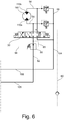
Figure 6 shows a third alternative exemplary subsystem of the hydraulic system applying the presented solution and relating toFigure 3 . -
Figure 7 shows a fourth alternative exemplary subsystem of the hydraulic system applying the presented solution and relating toFigure 3 . - An example of movable members controlled by the hydraulic system according to the solution is shown in
Figure 1 . The movable members relate to aboom crane 210. - The
boom crane 210 can be turned in lateral directions, and it typically comprises two or more arms orboom parts joint 220. In the example ofFigure 1 , theboom part 214 is connected by means of ajoint 218 to abase 212 providing swivelling movements. Thebase 212 may be a part of a chassis of a working machine. Alternatively, thebase 212 is connected to the chassis by means of aswivelling device 222 providing turning in the lateral directions. The positions of theboom crane 210 and its boom parts are controlled by actuators to generate hoisting and lowering movements of an implement or a tool connected to the end of theoutermost boom part 216. Typically, the actuator is a hydraulic cylinder utilizing hydraulic energy which is transmitted to the actuator by means of lines, i.e. hydraulic transmission lines. A hydraulic system is needed for generating the hydraulic energy and it is placed e.g. in the chassis or on the boom crane. Typically, one boom part is telescopically operating, for example theoutermost boom part 216. - A
cylinder 224 is connected between thebase 212 and theboom part 214 for lifting and lowering theboom part 214. Acylinder 226 is connected between theboom part 214 and theboom part 216 for lifting and lowering theboom part 216. Recyclable potential energy is generated in a chamber of thecylinder 224 when lowering theboom part 214 with the help of the weight of both a load and theboom parts cylinder 226 when lowering theboom part 216 with the help of the weight of both the load and theboom part 216. - In the example of
Figure 1 , thepiston rod 224a of thecylinder 224 is connected to theboom part 214 for controlling theboom part 214 and hydraulic energy is generated in the bottom chamber of thecylinder 224. - The presented solution can be utilized to control the actuators in
Figure 1 and is represented by an exemplary hydraulic system shown inFigures 2 and3 . In the subsystems ofFigures 2 and3 the actuators in use are double acting hydraulic cylinders. - The system represented by the subsystems of
Figures 2 and3 includes a hydraulic circuit for recovering hydraulic energy. The components necessary for the hydraulic circuit are as explained in the following description. Other components for good controllability of the system, subsystems and the hydraulic circuit are as explained in the following description. Various combinations of the presented components may be used for realizing the system, the subsystems or the hydraulic circuit based on different needs and applications. - Hydraulic transmission lines between various components of the system are designated by solid lines, and pressure sensing hydraulic transmission lines are designated by dashed lines. The figures show one example to create connections between the lines and the various components of the presented system. Other examples or alternatives are mentioned in this description.
- A line may have branches for allowing various components to be connected to the line or to isolate a section of the line from another section of the line. Two lines may be connected to each other at several alternative locations or at a component such that the lines are in communication with each other so that flow of fluid is made possible.
- Various components may be in communication with each other via lines between the components. The line may be a hose, a pipe or a channel, or a combination of the same. The channel may be located in e.g. a block-like element connecting two separate components or several components. In the presented solution, a line may be connected to another line at a location at the end of the other line or along the other line, or, at a location where the line is connected to a component, e.g. a valve.
- Various components of the system may receive electronic control signals from a
system controller 120, which is e.g. a microcomputer based device. Thesystem controller 120 may receive inputs from operator input devices such as a joystick. - Pressurized hydraulic fluid is provided by at least one
pump 32 driven by e.g. a motor which serves as the prime mover of the hydraulic system. The motor may be an engine in a mobile working machine or a separate motor, e.g. an electric motor. - The hydraulic system is incorporated in equipment, a boom crane or a mobile working machine that has movable members operated by hydraulically driven actuators, such as
cylinders 24 and 26 withpiston rods first cylinder 24 is a double acting type in that pressurized fluid can be applied to either side of itspiston rod 24a. The second cylinder 26 is a double acting type and pressurized fluid can be applied to either side of itspiston rod 26a. - According to an example and the subsystem of
Figure 2 , afirst chamber 24b of thefirst cylinder 24 is the chamber supplying fluid under pressure and providing potential energy for recovery. Thefirst chamber 24b is the bottom chamber of thecylinder 24. For the case shown inFigure 1 thefirst cylinder 24 inFigure 2 is used as theactuator 224 and controls theboom part 214. Thefirst chamber 24b is driven by the flow of fluid from thepump 32 to raise a load. - According to an example and
Figure 2 , potential energy is available from thefirst cylinder 24 with cylinder differential connection implemented e.g. with avalve 112 connecting and disconnecting the first andsecond chambers first cylinder 24 or the lines leading to them. Thevalve 112 is e.g. an electrically controlled shut-off valve. When in an open state, thevalve 112 leads hydraulic fluid from the piston side chamber of the first cylinder 24 (i.e. thefirst chamber 24b) to the piston rod side chamber of the first cylinder 24 (i.e. thesecond chamber 24c), or vice versa. Thus, the moving speed of thefirst cylinder 24 and itspiston rod 24a increases. - According to another example of the presented solution, the
first cylinder 24 inFigure 2 is used as theactuator 226 ofFigure 1 connected between theboom parts boom part 216. In that example the second cylinder 26 ofFigure 3 controls theboom part 214 and thefirst chamber 26b of the second cylinder 26 is driven by the flow of fluid from thepump 32 to raise a load. - A
directional control valve 28 controls the flow of hydraulic fluid into and out of the twochambers cylinder 24. Adirectional control valve 30 controls the flow of hydraulic fluid into and out of the twochambers pump 32 is supplied viasupply lines directional control valves common supply line 105 receiving hydraulic fluid from thepump 32. -
Tank lines directional control valves tank 34 receiving hydraulic fluid from the system. The system may comprise several tanks or several connections to a tank. The system may comprise separate tank lines for each directional control valve. The tank lines may include branch tank lines leading hydraulic fluid from an appropriate component. The tank lines may be connected to acommon tank line 106 leading hydraulic fluid to thetank 34. - According to an example and
Figure 2 , the system may further comprise anadditional tank line 107 for leading hydraulic fluid from thedirectional control valve 28 to thetank 34. Thetank line 107 may be used to bypass components and lines connected to thetank line 80. Thetank line 107 may be connected to thecommon tank line 106. InFigures 2 and4 thetank line 107 is not necessary when thetank line 80 only is used for receiving hydraulic fluid from thedirectional control valve 28 and thedirectional control valve 28 is not equipped with a port or channeling for thetank line 107. - The
directional control valves directional control valves - The first
directional control valve 28 with its first state controls the flow of fluid from thesupply line 46 to thefirst chamber 24b of thefirst cylinder 24 and the flow of fluid drained from thesecond chamber 24c of thefirst cylinder 24 to thetank line 80 or to thetank line 107 as shown inFigure 2 . - The first
directional control valve 28 with its second state controls the flow of fluid drained from thefirst chamber 24b of thefirst cylinder 24 to thetank line 80. According to an example, thesecond chamber 24c of thefirst cylinder 24 is disconnected from thesupply line 46 in the second state. According to an example, thesecond chamber 24c of thefirst cylinder 24, thesupply line 46 and thetank line 107 are closed in the second state. - The first
directional control valve 28 or the seconddirectional control valve 30, or both of them, are proportional control valves operated electrically, hydraulically, mechanically or pneumatically. Thedirectional control valves directional control valves system controller 120. - Additionally or as an alternative to the second state, the first
directional control valve 28 may further have a third state in which it controls the flow of fluid from thesupply line 46 to thesecond chamber 24c of thefirst cylinder 24 and the flow of fluid drained from thefirst chamber 24b of thecylinder 24 to thetank line 80. According to an example, thetank line 107 is closed in the third state. - The first
directional control valve 28 may further have a closed state disconnecting or shutting thesupply line 46, thesecond chamber 24c of thefirst cylinder 24, thefirst chamber 24b of first thecylinder 24 and thetank lines 80 and 170. Thus, the firstdirectional control valve 28 may have at least one state disconnecting thetank line 80 and therecovery line 64 from the first actuator. - The first and third states of the first
directional control valve 28 are used for moving thepiston rod 24a in and out. The second state, and the third state, are in use when recovering hydraulic energy. - The second cylinder 26 comprises the
first chamber 26b and thesecond chamber 26c. The seconddirectional control valve 30 with its first state controls the flow of fluid from thesupply line 82 to thefirst chamber 26b of the second cylinder 26 and the flow of fluid drained from thesecond chamber 26c of the second cylinder 26 to thetank line 104. - The second
directional control valve 30 with its second state controls the flow of fluid drained from thefirst chamber 26b of the second cylinder 26 to thetank line 104. According to an example, thesecond chamber 26c of the second cylinder 26 is disconnected from thesupply line 82 in the second state. According to an example, thesecond chamber 26c of the second cylinder 26 and thesupply line 82 are closed in the second state. - Additionally or as an alternative to the second state, the second
directional control valve 30 may further have a third state in which it controls the flow of fluid from thesupply line 82 to thesecond chamber 26c of the second cylinder 26 and the flow of fluid drained from thefirst chamber 26b of the second cylinder 26 to thetank line 104. - The second
directional control valve 30 may further have a closed state disconnecting or shutting thesupply line 82, thesecond chamber 26c of the second cylinder 26, thefirst chamber 26b of the second cylinder 26 and thetank line 104. 9. Thus, the seconddirectional control valve 30 may have at least one state disconnecting therecovery line 64 or thesupply line 82 from the second actuator. - The first and second states of the second
directional control valve 30 are used for moving thepiston rod 26a in and out with or without the hydraulic fluid drained from thefirst cylinder 24. - According to an example and
Figure 2 , thepump 32 is a load-sensing variable displacement pump for improving energy efficiency of the system and reducing energy losses. Thepump 32 is configured to control its output flow of hydraulic fluid by matching the output flow with the load pressure sensed at the second cylinder 26. Thepump 32 may further be configured to match the output flow with the load pressure sensed at thefirst cylinder 24. - According to another example the
pump 32 is a fixed displacement pump with a 3-way pressure compensator valve. - The
pump 32 senses the load pressure by using e.g. a load sensing line in communication with a line, a port or a point representing the load pressure of an actuator in e.g. a chamber of a hydraulic cylinder. The load sensing line is connected to aload control unit 42 of thepump 32. - The
pump 32 has aload sensing line 60 in communication with thefirst chamber 26b of the second cylinder 26 when the seconddirectional control valve 30 is in the first state. Theload sensing line 60 may be in communication with thesecond chamber 26c of the second cylinder 26 when the seconddirectional control valve 30 is in the third state. - According to another example, the load pressure may be sensed by a pressure sensor connected to the
system controller 120 which controls theload control unit 42 or thepump 32. The pressure sensor is connected to a line, a port or a point representing the load pressure of an actuator in e.g. a chamber of a hydraulic cylinder. - The
pump 32 may further have aload sensing line 44 in communication with thefirst chamber 24b of thefirst cylinder 24 when the firstdirectional control valve 28 is in the first state. Theload sensing line 44 may be in communication with thesecond chamber 24c of thefirst cylinder 24 when the firstdirectional control valve 28 is in the third state. - According to the presented solution, the system comprises a
recovery line 64 receiving fluid under pressure from the firstdirectional control valve 28 via e.g. thetank line 80. The fluid under pressure is supplied from a first actuator represented by thefirst cylinder 24 and itsfirst chamber 24b when the firstdirectional control valve 28 is in the second state or in the third state. Therecovery line 64 conveys fluid under pressure for driving a second actuator represented by the second cylinder 26 via thesupply line 82. Fluid under pressure available in therecovery line 64 is supplied to thefirst chamber 26b of the second cylinder 26 when the seconddirectional control valve 30 is in the first state. - Fluid under pressure available in the
recovery line 64 may be supplied to thesecond chamber 26c of the second cylinder 26 when the seconddirectional control valve 30 is in the third state. - The system comprises a
check valve 74 which permits a flow of fluid from therecovery line 64 to thesupply line 82, e.g. via thecommon supply line 105. Thecheck valve 74 blocks the flow of fluid from thesupply line 82, or thecommon supply line 105, to therecovery line 64. Blocking is used when the fluid pressure in thesupply line 82 is higher than the fluid pressure in therecovery line 64 or thecommon supply line 105. - The system may further comprise a
check valve 78 which permits a flow of fluid from thepump 32 to thesupply line 82. Thecheck valve 78 blocks the reverse flow of fluid from thesupply line 82 to thepump 32. Thecheck valve 78 is used to protect thepump 32 when the fluid pressure in thesupply line 82 is higher than the fluid pressure of the hydraulic fluid delivered by thepump 32. - In the example of
Figure 2 , thecheck valve 78 further permits a flow of fluid only from thepump 32 to thesupply line 46 and thecommon supply line 105. Thecheck valve 78 also blocks the flow of fluid back to thepump 32. An additional check valve in thesupply line 46 instead of thecheck valve 78 may be used to permit a flow of fluid from thepump 32 only, or from thecommon supply line 105, to thesupply line 46 and to block the flow of fluid in the reverse direction. Thus, thecheck valve 78 may be located elsewhere in thesupply line 82 or thecommon supply line 105. - The presented system comprises a
pressure compensating valve 66 for regulating the recovery of the hydraulic energy. Thepressure compensating valve 66 controls the flow of fluid received from the firstdirectional control valve 28 and being led to a tank, e.g. thetank 34. The firstpressure compensating valve 66 is located in thetank line 80 or it is in communication with thetank line 80 and the tank or thecommon tank line 106. - The first
directional control valve 28, therecovery line 64 and thepressure compensating valve 66 are connected in such a way that fluid under pressure from the firstdirectional control valve 28 has a passage to both thepressure compensating valve 66 and therecovery line 64. According to an example andFigure 2 , therecovery line 64 is connected to thetank line 80 between the firstdirectional control valve 28 and thepressure compensating valve 66. - The
pressure compensating valve 66 is a pressure compensator used to maintain a preset pressure differential across a hydraulic component to minimize the influence of pressure variation on a flow rate passing through the component. In the example ofFigure 2 , the component is the firstdirectional control valve 28 in the second state or the third state. The pressure compensator has a controllable orifice and two fluid pressure sensing lines for controlling the controllable orifice. The controllable orifice is normally open when the pressure differential across a measuring orifice, i.e. the hydraulic component, is below a predetermined limit. Thepressure compensating valve 66 is configured to have a setting defining the predetermined limit which the pressure differential across the controllable orifice should not exceed. The setting is implemented by e.g. an adjustable spring. - The
pressure compensating valve 66 comprises two fluidpressure sensing lines pressure sensing line 67 is connected to a point in communication with therecovery line 64 and the fluid pressure in therecovery line 64. The second fluidpressure sensing line 68 is connected to a point in communication with the first actuator, i.e. thefirst chamber 24b of thefirst cylinder 24, when the firstdirectional control valve 28 is in the second state or the third state. - When the fluid pressure in the first actuator, i.e. in the
first chamber 24b of thefirst cylinder 24, rises to a level determined by the setting, thepressure compensating valve 66 starts controlling the flow of fluid from the first actuator or thefirst chamber 24b. Thus, the fluid pressure of therecovery line 64 rises and fluid under pressure is available for use. The fluid under pressure is used by the second actuator, i.e. the second cylinder 26. - Fluid under pressure available in both the
recovery line 64 and thesupply line 82, or thecommon supply line 105, is used for driving and controlling the second actuator when there is not enough fluid under pressure available solely from therecovery line 64. - According to an example and
Figure 2 , the firstdirectional control valve 28 is configured to connect the secondpressure sensing line 68 with thefirst chamber 24b of thefirst cylinder 24. For example, the internal structure or a moving spool, or both of them, of the firstdirectional control valve 28 comprises channels for connecting the secondpressure sensing line 68 with the first actuator or thefirst chamber 24b, or, with aline 48 connecting the first actuator or thefirst chamber 24b and the firstdirectional control valve 28. - The internal structure and the spool may further comprise channels for connecting the
load sensing line 44 with the first actuator, thefirst chamber 24b or theline 48. - The second
directional control valve 30 may be equipped with an internal structure or a moving spool, or both of them, with channels for connecting theload sensing line 60 with the second actuator or thefirst chamber 26b of the second cylinder 26, or, with aline 54 connecting the second actuator or thefirst chamber 26b and the seconddirectional control valve 30 in the first state. The same principle relating to the internal structure or the moving spool applies to the second state of the seconddirectional control valve 30 for connecting theload sensing line 60 with the second actuator or thesecond chamber 26c of the second cylinder 26, or, with aline 56 connecting the second actuator or thesecond chamber 26c and the seconddirectional control valve 30. - The hydraulic system in
Figures 2 and3 utilizes the fluid under pressure being forced from thefirst chamber 24b of thefirst cylinder 24 to be available in therecovery line 64 for driving the second actuator or the second cylinder 26 when the firstdirectional control valve 28 is in the second state or in the third state. The fluid pressure in therecovery line 64 is dependent on the fluid pressure in thefirst chamber 24b, and thepressure compensating valve 66 controls the fluid flow in therecovery line 64. - In a case when the fluid pressure needed for driving the second actuator or the second cylinder 26 is lower than the fluid pressure available in the
recovery line 64, and the seconddirectional control valve 30 is in the first or second state, then fluid under pressure from thefirst chamber 24b of thefirst cylinder 24 will flow to the second actuator or a chamber of the second cylinder 26 via therecovery line 64. The port of the second actuator or the chamber of the second cylinder 26 receiving the fluid under pressure will be determined by the selected state of the seconddirectional control valve 30. - Therefore, potential energy produced in the first actuator or the
first chamber 24b of thefirst cylinder 24 may be used in the second actuator. Fluid under pressure is available in therecovery line 64 independently of the state of the seconddirectional control valve 30. Thus, energy is saved when the firstdirectional control valve 28 is in the second state, or in the third state, and there is no need to supply fluid under pressure from thepump 32 to the first actuator or thefirst cylinder 24. Energy is saved even in a case where supplementing fluid under pressure is led to the first actuator or thesecond chamber 24c of thefirst cylinder 24 from thepump 32 in the third state of the firstdirectional control valve 28. - Additional energy is saved in at least the first state or the second state of the second
directional control valve 30 when the second actuator or the second cylinder 26 can be supplied with fluid under pressure from the first actuator or thefirst cylinder 24 only or partially supplemented with fluid under pressure from thepump 32 in the third state of the seconddirectional control valve 30. - The fluid under pressure that is not used will be directed to the
tank 34 or thecommon tank line 106 via thepressure compensating valve 66. Additionally, in the third state of the firstdirectional control valve 28, when driving the first actuator or thesecond chamber 24c of thefirst cylinder 24 with fluid under pressure from thepump 32, additional potential energy produced in the first actuator or thefirst chamber 24b of thefirst cylinder 24 may be used in the second actuator. - For good controllability of the first actuator, the
first cylinder 24 or the flows of fluid in the system, the system may be provided with a secondpressure compensating valve 70 in therecovery line 64. The secondpressure compensating valve 70 controls the flow of fluid from therecovery line 64 to thesupply line 82 or thecommon supply line 105 via thesecond check valve 74. The secondpressure compensating valve 70 is a pressure compensator and has two fluidpressure sensing lines - The first
pressure sensing line 72 is connected to a point in communication with therecovery line 64 and the fluid pressure inrecovery line 64. The secondpressure sensing line 84 is connected to a point in communication with the first actuator, i.e. thefirst chamber 24b of thefirst cylinder 24, when the firstdirectional control valve 28 is in the second state or the third state. - According to an example and
Figure 2 , the firstdirectional control valve 28 is configured to connect the secondpressure sensing line 84 and the first actuator or thefirst chamber 24b of thefirst cylinder 24. For example, the internal structure or a moving spool of the firstdirectional control valve 28 comprises channels for making necessary connections. Alternatively, the secondpressure sensing line 84 of the secondpressure compensating valve 70 is connected to the secondpressure sensing line 68 of the firstpressure compensating valve 66. - The second
pressure compensating valve 70 is a pressure compensator used for maintaining a preset pressure differential across the firstdirectional control valve 28 in the second state or the third state. The secondpressure compensating valve 70 is configured to have a setting defining a predetermined limit preferably higher than the predetermined limit of the firstpressure compensating valve 66. The setting is implemented with e.g. an adjustable spring. Fluid under pressure is available in therecovery line 64 for driving the second actuator or the second cylinder 26. - The system may further have in the supply line 46 a third
pressure compensating valve 86 for the firstdirectional control valve 28 for improved pressure control of the first actuator or thefirst cylinder 24. The thirdpressure compensating valve 86 has a firstpressure sensing line 87 in communication with or connected to thesupply line 46 and a secondpressure sensing line 85 in communication with the first actuator or thefirst chamber 24b of thefirst cylinder 24 when the firstdirectional control valve 28 is in the first state, or, with the first actuator or thesecond chamber 24c of thefirst cylinder 24 when the firstdirectional control valve 28 is in the third state. Alternatively, the secondpressure sensing line 85 is connected to the firstload sensing line 44 of thepump 32. - The system may further comprise, in the
supply line 82, a fourthpressure compensating valve 88 for the seconddirectional control valve 30 for improved pressure control of the second actuator or the second cylinder 26. The fourthpressure compensating valve 88 has a firstpressure sensing line 89 in communication with or connected to thesupply line 82 and a secondpressure sensing line 94 in communication with the second actuator or thefirst chamber 26b of the second cylinder 26 when the seconddirectional control valve 30 is in the first state, or, with the second actuator or thesecond chamber 26c of the second cylinder 26 when the seconddirectional control valve 30 is in the second or third state. Alternatively, the secondpressure sensing line 94 is connected to the secondload sensing line 60 of thepump 32. - The system may further have a first
anti-cavitation check valve 38 for allowing a flow of fluid from thetank line 104 or thecommon tank line 106 to the first actuator or thesecond chamber 24c of thefirst cylinder 24. Theanti-cavitation check valve 38 is used when the firstdirectional control valve 28 is in the second state. The system may have aline 50 connecting the firstdirectional control valve 28 and the first actuator or thesecond chamber 24c of thefirst cylinder 24. In an example, the firstanti-cavitation check valve 38 is located in aline 52 connecting thetank line 104 or thecommon tank line 106 to theline 50. Thus, theanti-cavitation check valve 38 connects the first actuator to a tank line, e.g. thetank line 106, for receiving substitute fluid from the tank line. - Additionally, the system may comprise a second
anti-cavitation check valve 90 for allowing a flow of fluid from thetank line 104, thecommon tank line 106, or theline 52 to the first actuator, thefirst chamber 24b of thefirst cylinder 24 or theline 48. - The system may comprise a
check valve 76 allowing a flow of fluid to thetank 34 from thecommon tank line 106 or thetank lines Figure 2 , thecheck valve 76 is located between thetank 34 and thepressure compensating valve 66. Thecheck valve 76 guarantees an adequate fluid pressure at the anti-cavitation check valves for avoiding cavitation. - The system may further comprise a third
anti-cavitation check valve 40 for allowing a flow of fluid from thetank line 104 or thecommon tank line 106 to the second actuator or thesecond chamber 26c of the second cylinder 26. The thirdanti-cavitation check valve 40 is used e.g. when the seconddirectional control valve 30 is in the second state or the fluid pressure of the second actuator decreases below the fluid pressure of thetank line 104. - The system may have the
line 56 connecting the seconddirectional control valve 30 and the second actuator or thesecond chamber 26c of the second cylinder 26. In an example andFigure 3 , the thirdanti-cavitation check valve 40 is located in aline 58 connecting thetank line 104 or thecommon tank line 106 to theline 56. - Additionally, the system may comprise a fourth
anti-cavitation check valve 92 for allowing a flow of fluid from thetank line 104 or thecommon tank line 106 to the second actuator, thefirst chamber 26b of the second cylinder 26 or theline 54. - The foregoing description was primarily directed to example embodiments of the presented solution. The presented solution is also used in apparatuses and systems other than a boom crane. The presented system may comprise additional cylinders or actuators driven by the hydraulic fluid supplied by the pump of the system. The additional cylinders or actuators are connected to e.g. the supply lines, the
common supply line 105, the tank lines and thecommon tank line 106 in the same manner as inFigure 3 . The presented system may comprise two or more subsystems as shown inFigure 2 and providing energy recovery. The presented system may comprise additional cylinders or actuators providing fluid under pressure as shown inFigure 2 . - In an alternative example, one or both
cylinders 24, 26 are installed upside down compared toFigure 1 . Thus, in the system ofFigure 2 , thesecond chamber 24c and thefirst chamber 24b switch places and potential energy is generated in thesecond chamber 24c. Thesecond chamber 24c is the piston rod side chamber of thefirst cylinder 24. The directional control valves of the system inFigure 2 may further have additional functionalities and states. - One or more of the
anti-cavitation check valves Figure 2 . - In
Figure 4 , the presented solution is further represented by a second exemplary hydraulic system in which thefirst cylinder 24 shown inFigure 2 is replaced with an actuator which is a pump-motor 108 having twoports motor 108 has two directions of flow. One direction of flow may be used to raise a load connected to the pump-motor 108 and the opposite direction of flow of fluid under pressure is generated by e.g. a lowering load. The pump-motor 108 may be of variable displacement type or fixed displacement type. The recovered energy in the form of pressurized fluid supplied by theport 108a is used to drive another simultaneous actuator function, e.g. the second actuator or the second cylinder 26 shown inFigure 3 . - The
port 108b of the pump-motor 108 is connected in a manner similar to thesecond chamber 24c of thefirst cylinder 24, and theport 108a of the pump-motor 108 is connected in a manner similar to thefirst chamber 24b of thefirst cylinder 24. The functionality, principles and details already explained and relating to the components of the subsystem shown inFigure 2 apply to the subsystem ofFigure 4 showing similar components. - In
Figure 5 , the presented solution is further represented by a third exemplary hydraulic system in which thefirst cylinder 24 shown inFigure 2 is replaced with an actuator which is ahydraulic cylinder 109. Thecylinder 109 is of a single acting type in that pressurized fluid can be supplied to achamber 109b on one side of itspiston rod 109a only. Thechamber 109b is driven by the flow of fluid from e.g. thepump 32 to e.g. raise a load. For example, a lowering load generates potential energy in thechamber 109b. The recovered energy in the form of pressurized fluid from thechamber 109b is used to drive another simultaneous actuator function, e.g. the second actuator or the second cylinder 26 shown inFigure 3 . - The
chamber 109b of thecylinder 109 is connected in a manner similar to thefirst chamber 24b of thefirst cylinder 24. The functionality, principles and details already explained and relating to the components of the subsystem shown inFigure 2 apply to the subsystem ofFigure 5 showing similar components. Theline 50 and theanti-cavitation check valve 38 ofFigure 2 are not necessary in the subsystem ofFigure 5 . Thetank line 107 ofFigure 2 is not necessary but may be included in the system ofFigure 5 and the firstdirectional control valve 28 ofFigure 5 may equipped correspondingly, e.g. with an additional port similar toFigure 2 . The firstdirectional control valve 28 may have a simplified configuration as shown inFigure 5 when used with thecylinder 109. Thedirectional control valve 28 controls the flow of hydraulic fluid into and out of thechamber 109b. Thedirectional control valve 28 ofFigure 5 may have less ports than inFigure 2 . - In
Figure 5 , the firstdirectional control valve 28 with its first state controls the flow of fluid from thesupply line 46 to thechamber 109b and with its second state controls the flow of fluid drained from thechamber 109b to thetank line 80. According to an example, in the second state thesupply line 46 is closed or in the first state thetank line 80 is closed. The firstdirectional control valve 28 may further have a closed state disconnecting or shutting thesupply line 46, thechamber 109b and thetank line 80. The first state of the firstdirectional control valve 28 is used for moving thepiston rod 109a out. The second state is in use when recovering hydraulic energy. - In
Figure 5 , thepressure sensing line 68, and thepressure sensing line 84, are connected to a point in communication with thechamber 109b when the firstdirectional control valve 28 is in the second state. According to an example andFigure 5 , the firstdirectional control valve 28 is configured to connect the secondpressure sensing line 68 and thechamber 109b by means of the internal structure or the moving spool of the firstdirectional control valve 28. Theload sensing line 44 is in communication with thechamber 109b when the firstdirectional control valve 28 is in the first state. - In
Figure 6 , the presented solution is further represented by a fourth exemplary hydraulic system in which the second cylinder 26 shown inFigure 3 is replaced with an actuator which is a motor 110 having twoports - The
port 110b of the motor 110 is connected in a manner similar to thesecond chamber 26c of the second cylinder 26 and theport 110a of the motor 110 is connected in a manner similar to thefirst chamber 26b of the second cylinder 26. The functionality, principles and details already explained and relating to the components of the subsystem shown inFigure 3 apply to the subsystem ofFigure 6 showing similar components. - Fluid under pressure available in the
recovery line 64 or in thesupply line 82, or both, is used for driving and controlling the motor 110. - In
Figure 7 , the presented solution is further represented by a fifth exemplary hydraulic system in which the cylinder 26 shown inFigure 3 is replaced with an actuator which is ahydraulic cylinder 111. Thecylinder 111 is of the single acting type in that pressurized fluid can be supplied to achamber 111b on one side of itspiston rod 111a only. Thechamber 111b is driven by fluid under pressure available in therecovery line 64 or in thesupply line 82, or both. - The
chamber 111b is connected in a manner similar to thefirst chamber 26b of the second cylinder 26. The functionality, principles and details already explained and relating to the components of the subsystem shown inFigure 3 apply to the subsystem ofFigure 7 showing similar components. Theline 56 and theanti-cavitation check valve 40 ofFigure 3 are not necessary in the subsystem ofFigure 7 . The seconddirectional control valve 30 may have a simplified configuration when used with thecylinder 111. Thedirectional control valve 30 controls the flow of hydraulic fluid into and out of thechamber 111b. Thedirectional control valve 30 ofFigure 7 may have less ports than inFigure 3 . - In
Figure 7 , the seconddirectional control valve 30 with its first state controls the flow of fluid from thesupply line 82 to thechamber 111b, and with its second state controls the flow of fluid drained from thechamber 111b to thetank line 104. According to an example, in the second state thesupply line 82 is closed or in the first state thetank 104 line is closed. The seconddirectional control valve 30 may further have a closed state disconnecting or shutting thesupply line 82, thechamber 111b and thetank line 104. The first state of the seconddirectional control valve 30 is used for moving thepiston rod 111a out. - In
Figure 7 , theload sensing line 60 is connected to a point in communication with thechamber 111b when the seconddirectional control valve 30 is in the first state. According to an example andFigure 7 , the seconddirectional control valve 30 is configured to connect theload sensing line 60 and thechamber 111b by means of the internal structure or the moving spool of the seconddirectional control valve 30. - According to further exemplary hydraulic systems of the presented solution, the subsystem of
Figure 2 may be replaced with one or both of the subsystems inFigures 4 and5 . In addition to the subsystem ofFigure 2 , the presented system may have one or both of the subsystems ofFigures 4 and5 . According to further exemplary hydraulic systems of the presented solution, the subsystem ofFigure 3 may be replaced with one or both of the subsystems inFigures 6 and7 . In addition to the subsystem ofFigure 3 , the presented system may have one or both of the subsystems inFigures 6 and7 . - Other components necessary for the basic functioning of the presented hydraulic circuit and controlling flows of fluid in the presented system may be added to the solution presented in the Figures.
- The solution is not limited solely to the above-presented embodiments, but it can be modified within the scope of the appended claims.
Claims (18)
- A hydraulic system for recovering hydraulic energy, the hydraulic system comprising at least:- a first actuator (24, 108, 109) for generating hydraulic energy and providing fluid under pressure,- a tank line (80) for receiving the fluid under pressure drained from the first actuator (24, 108, 109),- a second actuator (26, 110, 111) driven by the fluid under pressure drained from the first actuator (24, 108, 109),- a recovery line (64) for supplying the fluid under pressure drained from the first actuator (24, 108, 109) to the second actuator (26, 110, 111) for driving the second actuator (26, 110, 111), wherein the fluid pressure in the recovery line (64) is dependent on the fluid pressure in the first actuator (24, 108, 109),- a first directional control valve (28) having at least one state in which the first actuator (24, 108, 109) is in communication with the tank line (80) and the recovery line (64), wherein the tank line (80) and the recovery line (64) receive the fluid under pressure from the first actuator (24, 108, 109) via the first directional control valve (28),- a second directional control valve (30) having at least one state in which the second actuator (26, 110, 111) is in communication with the recovery line (64), wherein the second actuator (26, 110, 111) receives the fluid under pressure from the recovery line (64) via the second directional control valve (30),characterised in that the hydraulic system further comprises:- a pressure compensating valve (66) which controls flow of fluid in the tank line (80) and maintains a fluid pressure differential across the first directional control valve (28) when the first directional control valve (28) is in the state connecting the first actuator (24, 108, 109), the tank line (80) and the recovery line (64), which fluid pressure differential is dependent on a setting of the first pressure compensating valve (66), wherein the first pressure compensating valve (66) is provided with- a first fluid pressure sensing line (67) in communication with the recovery line (64), and- a second fluid pressure sensing line (68) in communication with the first actuator (24, 108, 109) when the first directional control valve (28) is in the state connecting the first actuator (24, 108, 109), the tank line (80) and the recovery line (64).
- The system according to claim 1, wherein the first actuator is a double acting hydraulic cylinder (24), a single acting hydraulic cylinder (109) or a hydraulic pump-motor (108), and wherein the second actuator is a double acting hydraulic cylinder (26), a single acting hydraulic cylinder (111) or a hydraulic motor (110).
- The system according to claim 1 or 2, wherein the system comprises several actuators (24, 108, 109) generating hydraulic energy and providing fluid under pressure for driving one or more other actuators (26, 110, 111), or, the system comprises several actuators (26, 110, 111) driven by fluid under pressure drained from one or more actuators (24, 108, 109) generating hydraulic energy and providing fluid under pressure.
- The system according to any one of the claims 1 to 3, wherein the hydraulic system further comprises a check valve (74) in the recovery line (64) for blocking flow of fluid from the second actuator (26, 110, 111) to the recovery line (64).
- The system according to any one of the claims 1 to 4, wherein the system further comprises:- a supply line (46, 105) for supplying fluid under pressure to the first actuator (24, 108, 109) to drive the first actuator (24, 108, 109), and- another tank line (107) for receiving fluid drained from the first actuator (24, 108, 109),- wherein the first directional control valve (28) further has a state connecting the supply line (46) and the other tank line (107) to the first actuator (24, 108, 109).
- The system according to claim 5, wherein the second fluid pressure sensing line (68) of the pressure compensating valve (66) is disconnected from the first actuator (24, 108, 109) when the first directional control valve (28) is in the state connecting the first actuator (24, 108, 109), the supply line (46) and the other tank line (107).
- The system according to any one of the claims 1 to 6, wherein the system further comprises a supply line (82, 105) for supplying fluid under pressure to the second actuator (26, 110, 111), wherein the second directional control valve (30) further has at least one state in which the second actuator (26, 110, 111) is in communication with the recovery line (64) and the supply line (82, 105) such that fluid under pressure is available both in the recovery line (64) and the supply line (82) for driving the second actuator (26, 110, 111).
- The system according to any one of the claims 1 to 7, wherein the first directional control valve (28) is configured to connect the second pressure sensing line (68) of the pressure compensating valve (66) with the first actuator (24, 108, 109).
- The system according to any one of the claims 1 to 8, wherein the system further comprises:- a tank line (104) for receiving fluid drained from the second actuator (26, 110, 111),- wherein the second directional control valve (30) further has at least one state connecting the tank line (104) to the second actuator (26, 110, 111).
- The system according to any one of claims 1 to 9, wherein the system further comprises:- a second pressure compensating valve (70) which controls the flow of fluid in the recovery line (64) and maintains a fluid pressure differential across the first directional control valve (28) when the first directional control valve (28) is in the state connecting the first actuator (24, 108, 109), the tank line (80) and the recovery line (64), which fluid pressure differential is dependent on a setting of the second pressure compensating valve (70), wherein the second pressure compensating valve (70) is provided with- a first pressure sensing line (72) in communication with the recovery line (64), and- a second pressure sensing line (84) in communication with the first actuator (24, 108, 109) when the first directional control valve (28) is in the state connecting the first actuator (24, 108, 109), the tank line (80) and the recovery line (64).
- The system according to claim 10, wherein the first directional control valve (28) is configured to connect the second pressure sensing line (84) of the second pressure compensating valve (70) with the first actuator (24, 108, 109), or, the second pressure sensing line (84) of the second pressure compensating valve (70) is connected to the second pressure sensing line (68) of the first pressure compensating valve (66).
- The system according to any one of the claims 1 to 11, wherein the recovery line (64) is connected to the tank line (80) at a point located between the first directional control valve (28) and the pressure compensating valve (66).
- The system according to any one of the claims 1 to 12, wherein the system further comprises a pump (32) supplying fluid under pressure to a supply line (46, 82, 105), wherein the pump (32) is of the load-sensing type and has a first load sensing line (44) in communication with the first actuator (24, 108, 109) when the first directional control valve (28) is in the state connecting the first actuator (24, 108, 109), the tank line (80) and the recovery line (64).
- The system according to claim 13, wherein the first directional control valve (28) is configured to connect the first load sensing line (44) with the first actuator (24, 108, 109).
- The system according to claim 13 or 14, wherein the pump (32) is further provided with a second load sensing line (60) in communication with the second actuator (26, 110, 111) when the second directional control valve (30) is in the state connecting the second actuator (26, 110, 111) and the recovery line (64) or the supply line (46, 82, 105).
- The system according to any one of the claims 1 to 15, wherein the system further comprises a pressure compensating valve (86) which controls the flow of fluid supplied to the first directional control valve (28), which pressure compensating valve (86) is provided with- a first pressure sensing line (87) in communication with the flow of fluid supplied to the first directional control valve (28), and- a second pressure sensing line (85) in communication with the first actuator (24, 108, 109) when the first directional control valve (28) is in the state connecting the first actuator (24, 108, 109), the tank line (80) and the recovery line (64).
- The system according to any one of the claims 1 to 16, wherein the system further comprises a pressure compensating valve (88) which controls the flow of fluid supplied to the second directional control valve (30), which pressure compensating valve (88) is provided with- a first pressure sensing line (89) in communication with the flow of fluid supplied to the second directional control valve (30), and- a second pressure sensing line (94) in communication with the second actuator (26, 110, 111) when the second directional control valve (30) is in the state connecting the recovery line (64), or the supply line (46, 82, 105), and the second actuator (26, 110, 111).
- The system according to any one of the claims 1 to 17, wherein the system further comprises a valve (112) for cylinder differential connection, which valve has a state leading hydraulic fluid between a piston side chamber of the first actuator (24) and a piston rod side chamber of the first actuator (24).
Priority Applications (2)
| Application Number | Priority Date | Filing Date | Title |
|---|---|---|---|
| EP14397522.5A EP2955389B1 (en) | 2014-06-13 | 2014-06-13 | Hydraulic system with energy recovery |
| US14/735,829 US9797419B2 (en) | 2014-06-13 | 2015-06-10 | Hydraulic system with energy recovery |
Applications Claiming Priority (1)
| Application Number | Priority Date | Filing Date | Title |
|---|---|---|---|
| EP14397522.5A EP2955389B1 (en) | 2014-06-13 | 2014-06-13 | Hydraulic system with energy recovery |
Publications (2)
| Publication Number | Publication Date |
|---|---|
| EP2955389A1 EP2955389A1 (en) | 2015-12-16 |
| EP2955389B1 true EP2955389B1 (en) | 2019-05-22 |
Family
ID=51176310
Family Applications (1)
| Application Number | Title | Priority Date | Filing Date |
|---|---|---|---|
| EP14397522.5A Not-in-force EP2955389B1 (en) | 2014-06-13 | 2014-06-13 | Hydraulic system with energy recovery |
Country Status (2)
| Country | Link |
|---|---|
| US (1) | US9797419B2 (en) |
| EP (1) | EP2955389B1 (en) |
Families Citing this family (7)
| Publication number | Priority date | Publication date | Assignee | Title |
|---|---|---|---|---|
| DE102017219645A1 (en) * | 2017-11-06 | 2019-05-09 | Zf Friedrichshafen Ag | Valve, hydraulic system and motor vehicle transmission |
| JP6914206B2 (en) * | 2018-01-11 | 2021-08-04 | 株式会社小松製作所 | Hydraulic circuit |
| CN108755823A (en) * | 2018-07-05 | 2018-11-06 | 伊婕 | A kind of excavator with pressure difference liquid energy and potential energy recovery device |
| US10641297B2 (en) * | 2018-08-17 | 2020-05-05 | Robert Bosch Gmbh | Hydraulic control valve |
| CN110872857A (en) * | 2019-11-29 | 2020-03-10 | 徐州徐工液压件有限公司 | Multifunctional energy recovery device and hydraulic excavator system carrying same |
| TR202010537A2 (en) * | 2020-07-03 | 2021-01-21 | Hidromek Hidrolik Ve Mekanik Makina Imalat Sanayi Ve Ticaret Anonim Sirketi | HYDRAULIC SYSTEM PROVIDING ENERGY RECOVERY WITH DOUBLE SLIDING DIRECTION VALVES DURING LIFTING? |
| WO2024058689A1 (en) * | 2022-09-12 | 2024-03-21 | Epiroc Rock Drills Aktiebolag | Hydraulic system |
Family Cites Families (6)
| Publication number | Priority date | Publication date | Assignee | Title |
|---|---|---|---|---|
| JP2004011168A (en) * | 2002-06-04 | 2004-01-15 | Komatsu Ltd | Construction machinery |
| SE531309C2 (en) * | 2006-01-16 | 2009-02-17 | Volvo Constr Equip Ab | Control system for a working machine and method for controlling a hydraulic cylinder of a working machine |
| DE102006060351B8 (en) * | 2006-12-20 | 2008-07-24 | Sauer-Danfoss Gmbh & Co Ohg | Hydraulic circuit with energy recovery |
| DE102008038992A1 (en) * | 2008-08-13 | 2010-02-18 | Schuler Smg Gmbh & Co. Kg | Hydraulic press, has two pumps and flywheel that is utilized as energy storage, where hydraulic fluid is supplied by one of pumps which works as motor in dwell phase for operating flywheel |
| WO2010138029A1 (en) * | 2009-05-29 | 2010-12-02 | Volvo Construction Equipment Ab | A hydraulic system and a working machine comprising such a hydraulic system |
| JP5574375B2 (en) * | 2010-06-30 | 2014-08-20 | キャタピラー エス エー アール エル | Energy regeneration control circuit and work machine |
-
2014
- 2014-06-13 EP EP14397522.5A patent/EP2955389B1/en not_active Not-in-force
-
2015
- 2015-06-10 US US14/735,829 patent/US9797419B2/en not_active Expired - Fee Related
Also Published As
| Publication number | Publication date |
|---|---|
| US20150361998A1 (en) | 2015-12-17 |
| EP2955389A1 (en) | 2015-12-16 |
| US9797419B2 (en) | 2017-10-24 |
Similar Documents
| Publication | Publication Date | Title |
|---|---|---|
| EP2955389B1 (en) | Hydraulic system with energy recovery | |
| KR101683317B1 (en) | Device for hydraulic pump control in heavy equipment | |
| US5490384A (en) | Hydraulic flow priority system | |
| US20130098464A1 (en) | Closed-Loop Hydraulic System Having Regeneration Configuration | |
| EP3106677B1 (en) | Hydraulic drive appraratus for construction machine | |
| US9528531B2 (en) | Hydraulic drive apparatus for work machine | |
| US9932993B2 (en) | System and method for hydraulic energy recovery | |
| US10710855B2 (en) | Hydraulic driving system | |
| JP6514522B2 (en) | Hydraulic drive system of unloading valve and hydraulic shovel | |
| US11318988B2 (en) | Hydraulic steering control system | |
| CN106321537B (en) | Hydraulic control system and corresponding mobile working device | |
| CN109563695B (en) | Control valve for excavator and excavator | |
| EP3311034B1 (en) | Load sensing hydraulic system for a working machine | |
| US20110030816A1 (en) | Control system for controlling a directional control valve | |
| EP3683453B1 (en) | Driving device of construction equipment | |
| EP2910796B1 (en) | Assembly with a control valve device with a float position | |
| US20140033698A1 (en) | Meterless hydraulic system having force modulation | |
| KR102385608B1 (en) | Control valves for shovels and shovels | |
| CN105971043B (en) | Excavator | |
| US8806862B2 (en) | Smart flow sharing system | |
| US20170108015A1 (en) | Independent Metering Valves with Flow Sharing | |
| CN108909832B (en) | Steering hydraulic system and loader | |
| KR101506743B1 (en) | Hydraulic pump control apparatus for construction machinery | |
| EP1522740A1 (en) | A cushion valve for hydraulic remote controls of hydraulic directional valves | |
| CN111677704B (en) | Hydraulic system and engineering machinery |
Legal Events
| Date | Code | Title | Description |
|---|---|---|---|
| PUAI | Public reference made under article 153(3) epc to a published international application that has entered the european phase |
Free format text: ORIGINAL CODE: 0009012 |
|
| AK | Designated contracting states |
Kind code of ref document: A1 Designated state(s): AL AT BE BG CH CY CZ DE DK EE ES FI FR GB GR HR HU IE IS IT LI LT LU LV MC MK MT NL NO PL PT RO RS SE SI SK SM TR |
|
| AX | Request for extension of the european patent |
Extension state: BA ME |
|
| 17P | Request for examination filed |
Effective date: 20160613 |
|
| RBV | Designated contracting states (corrected) |
Designated state(s): AL AT BE BG CH CY CZ DE DK EE ES FI FR GB GR HR HU IE IS IT LI LT LU LV MC MK MT NL NO PL PT RO RS SE SI SK SM TR |
|
| RIC1 | Information provided on ipc code assigned before grant |
Ipc: F15B 11/024 20060101AFI20181029BHEP Ipc: E02F 9/22 20060101ALI20181029BHEP Ipc: F15B 21/14 20060101ALI20181029BHEP |
|
| GRAP | Despatch of communication of intention to grant a patent |
Free format text: ORIGINAL CODE: EPIDOSNIGR1 |
|
| STAA | Information on the status of an ep patent application or granted ep patent |
Free format text: STATUS: GRANT OF PATENT IS INTENDED |
|
| INTG | Intention to grant announced |
Effective date: 20190104 |
|
| GRAS | Grant fee paid |
Free format text: ORIGINAL CODE: EPIDOSNIGR3 |
|
| GRAA | (expected) grant |
Free format text: ORIGINAL CODE: 0009210 |
|
| STAA | Information on the status of an ep patent application or granted ep patent |
Free format text: STATUS: THE PATENT HAS BEEN GRANTED |
|
| AK | Designated contracting states |
Kind code of ref document: B1 Designated state(s): AL AT BE BG CH CY CZ DE DK EE ES FI FR GB GR HR HU IE IS IT LI LT LU LV MC MK MT NL NO PL PT RO RS SE SI SK SM TR |
|
| REG | Reference to a national code |
Ref country code: GB Ref legal event code: FG4D |
|
| REG | Reference to a national code |
Ref country code: CH Ref legal event code: EP |
|
| REG | Reference to a national code |
Ref country code: IE Ref legal event code: FG4D |
|
| REG | Reference to a national code |
Ref country code: DE Ref legal event code: R096 Ref document number: 602014047154 Country of ref document: DE |
|
| REG | Reference to a national code |
Ref country code: AT Ref legal event code: REF Ref document number: 1136462 Country of ref document: AT Kind code of ref document: T Effective date: 20190615 |
|
| REG | Reference to a national code |
Ref country code: NL Ref legal event code: MP Effective date: 20190522 |
|
| REG | Reference to a national code |
Ref country code: LT Ref legal event code: MG4D |
|
| PG25 | Lapsed in a contracting state [announced via postgrant information from national office to epo] |
Ref country code: AL Free format text: LAPSE BECAUSE OF FAILURE TO SUBMIT A TRANSLATION OF THE DESCRIPTION OR TO PAY THE FEE WITHIN THE PRESCRIBED TIME-LIMIT Effective date: 20190522 Ref country code: NO Free format text: LAPSE BECAUSE OF FAILURE TO SUBMIT A TRANSLATION OF THE DESCRIPTION OR TO PAY THE FEE WITHIN THE PRESCRIBED TIME-LIMIT Effective date: 20190822 Ref country code: ES Free format text: LAPSE BECAUSE OF FAILURE TO SUBMIT A TRANSLATION OF THE DESCRIPTION OR TO PAY THE FEE WITHIN THE PRESCRIBED TIME-LIMIT Effective date: 20190522 Ref country code: NL Free format text: LAPSE BECAUSE OF FAILURE TO SUBMIT A TRANSLATION OF THE DESCRIPTION OR TO PAY THE FEE WITHIN THE PRESCRIBED TIME-LIMIT Effective date: 20190522 Ref country code: LT Free format text: LAPSE BECAUSE OF FAILURE TO SUBMIT A TRANSLATION OF THE DESCRIPTION OR TO PAY THE FEE WITHIN THE PRESCRIBED TIME-LIMIT Effective date: 20190522 Ref country code: HR Free format text: LAPSE BECAUSE OF FAILURE TO SUBMIT A TRANSLATION OF THE DESCRIPTION OR TO PAY THE FEE WITHIN THE PRESCRIBED TIME-LIMIT Effective date: 20190522 Ref country code: SE Free format text: LAPSE BECAUSE OF FAILURE TO SUBMIT A TRANSLATION OF THE DESCRIPTION OR TO PAY THE FEE WITHIN THE PRESCRIBED TIME-LIMIT Effective date: 20190522 Ref country code: PT Free format text: LAPSE BECAUSE OF FAILURE TO SUBMIT A TRANSLATION OF THE DESCRIPTION OR TO PAY THE FEE WITHIN THE PRESCRIBED TIME-LIMIT Effective date: 20190922 Ref country code: FI Free format text: LAPSE BECAUSE OF FAILURE TO SUBMIT A TRANSLATION OF THE DESCRIPTION OR TO PAY THE FEE WITHIN THE PRESCRIBED TIME-LIMIT Effective date: 20190522 |
|
| PG25 | Lapsed in a contracting state [announced via postgrant information from national office to epo] |
Ref country code: RS Free format text: LAPSE BECAUSE OF FAILURE TO SUBMIT A TRANSLATION OF THE DESCRIPTION OR TO PAY THE FEE WITHIN THE PRESCRIBED TIME-LIMIT Effective date: 20190522 Ref country code: LV Free format text: LAPSE BECAUSE OF FAILURE TO SUBMIT A TRANSLATION OF THE DESCRIPTION OR TO PAY THE FEE WITHIN THE PRESCRIBED TIME-LIMIT Effective date: 20190522 Ref country code: BG Free format text: LAPSE BECAUSE OF FAILURE TO SUBMIT A TRANSLATION OF THE DESCRIPTION OR TO PAY THE FEE WITHIN THE PRESCRIBED TIME-LIMIT Effective date: 20190822 Ref country code: GR Free format text: LAPSE BECAUSE OF FAILURE TO SUBMIT A TRANSLATION OF THE DESCRIPTION OR TO PAY THE FEE WITHIN THE PRESCRIBED TIME-LIMIT Effective date: 20190823 |
|
| REG | Reference to a national code |
Ref country code: AT Ref legal event code: MK05 Ref document number: 1136462 Country of ref document: AT Kind code of ref document: T Effective date: 20190522 |
|
| REG | Reference to a national code |
Ref country code: DE Ref legal event code: R119 Ref document number: 602014047154 Country of ref document: DE |
|
| PG25 | Lapsed in a contracting state [announced via postgrant information from national office to epo] |
Ref country code: CZ Free format text: LAPSE BECAUSE OF FAILURE TO SUBMIT A TRANSLATION OF THE DESCRIPTION OR TO PAY THE FEE WITHIN THE PRESCRIBED TIME-LIMIT Effective date: 20190522 Ref country code: SK Free format text: LAPSE BECAUSE OF FAILURE TO SUBMIT A TRANSLATION OF THE DESCRIPTION OR TO PAY THE FEE WITHIN THE PRESCRIBED TIME-LIMIT Effective date: 20190522 Ref country code: EE Free format text: LAPSE BECAUSE OF FAILURE TO SUBMIT A TRANSLATION OF THE DESCRIPTION OR TO PAY THE FEE WITHIN THE PRESCRIBED TIME-LIMIT Effective date: 20190522 Ref country code: DK Free format text: LAPSE BECAUSE OF FAILURE TO SUBMIT A TRANSLATION OF THE DESCRIPTION OR TO PAY THE FEE WITHIN THE PRESCRIBED TIME-LIMIT Effective date: 20190522 Ref country code: RO Free format text: LAPSE BECAUSE OF FAILURE TO SUBMIT A TRANSLATION OF THE DESCRIPTION OR TO PAY THE FEE WITHIN THE PRESCRIBED TIME-LIMIT Effective date: 20190522 Ref country code: AT Free format text: LAPSE BECAUSE OF FAILURE TO SUBMIT A TRANSLATION OF THE DESCRIPTION OR TO PAY THE FEE WITHIN THE PRESCRIBED TIME-LIMIT Effective date: 20190522 |
|
| REG | Reference to a national code |
Ref country code: CH Ref legal event code: PL |
|
| PG25 | Lapsed in a contracting state [announced via postgrant information from national office to epo] |
Ref country code: MC Free format text: LAPSE BECAUSE OF FAILURE TO SUBMIT A TRANSLATION OF THE DESCRIPTION OR TO PAY THE FEE WITHIN THE PRESCRIBED TIME-LIMIT Effective date: 20190522 Ref country code: SM Free format text: LAPSE BECAUSE OF FAILURE TO SUBMIT A TRANSLATION OF THE DESCRIPTION OR TO PAY THE FEE WITHIN THE PRESCRIBED TIME-LIMIT Effective date: 20190522 Ref country code: IT Free format text: LAPSE BECAUSE OF FAILURE TO SUBMIT A TRANSLATION OF THE DESCRIPTION OR TO PAY THE FEE WITHIN THE PRESCRIBED TIME-LIMIT Effective date: 20190522 |
|
| PLBE | No opposition filed within time limit |
Free format text: ORIGINAL CODE: 0009261 |
|
| REG | Reference to a national code |
Ref country code: BE Ref legal event code: MM Effective date: 20190630 |
|
| STAA | Information on the status of an ep patent application or granted ep patent |
Free format text: STATUS: NO OPPOSITION FILED WITHIN TIME LIMIT |
|
| PG25 | Lapsed in a contracting state [announced via postgrant information from national office to epo] |
Ref country code: TR Free format text: LAPSE BECAUSE OF FAILURE TO SUBMIT A TRANSLATION OF THE DESCRIPTION OR TO PAY THE FEE WITHIN THE PRESCRIBED TIME-LIMIT Effective date: 20190522 |
|
| 26N | No opposition filed |
Effective date: 20200225 |
|
| GBPC | Gb: european patent ceased through non-payment of renewal fee |
Effective date: 20190822 |
|
| PG25 | Lapsed in a contracting state [announced via postgrant information from national office to epo] |
Ref country code: PL Free format text: LAPSE BECAUSE OF FAILURE TO SUBMIT A TRANSLATION OF THE DESCRIPTION OR TO PAY THE FEE WITHIN THE PRESCRIBED TIME-LIMIT Effective date: 20190522 Ref country code: IE Free format text: LAPSE BECAUSE OF NON-PAYMENT OF DUE FEES Effective date: 20190613 Ref country code: DE Free format text: LAPSE BECAUSE OF NON-PAYMENT OF DUE FEES Effective date: 20200101 |
|
| PG25 | Lapsed in a contracting state [announced via postgrant information from national office to epo] |
Ref country code: SI Free format text: LAPSE BECAUSE OF FAILURE TO SUBMIT A TRANSLATION OF THE DESCRIPTION OR TO PAY THE FEE WITHIN THE PRESCRIBED TIME-LIMIT Effective date: 20190522 Ref country code: LU Free format text: LAPSE BECAUSE OF NON-PAYMENT OF DUE FEES Effective date: 20190613 Ref country code: BE Free format text: LAPSE BECAUSE OF NON-PAYMENT OF DUE FEES Effective date: 20190630 Ref country code: CH Free format text: LAPSE BECAUSE OF NON-PAYMENT OF DUE FEES Effective date: 20190630 Ref country code: LI Free format text: LAPSE BECAUSE OF NON-PAYMENT OF DUE FEES Effective date: 20190630 |
|
| PG25 | Lapsed in a contracting state [announced via postgrant information from national office to epo] |
Ref country code: FR Free format text: LAPSE BECAUSE OF NON-PAYMENT OF DUE FEES Effective date: 20190722 |
|
| PG25 | Lapsed in a contracting state [announced via postgrant information from national office to epo] |
Ref country code: GB Free format text: LAPSE BECAUSE OF NON-PAYMENT OF DUE FEES Effective date: 20190822 |
|
| PG25 | Lapsed in a contracting state [announced via postgrant information from national office to epo] |
Ref country code: CY Free format text: LAPSE BECAUSE OF FAILURE TO SUBMIT A TRANSLATION OF THE DESCRIPTION OR TO PAY THE FEE WITHIN THE PRESCRIBED TIME-LIMIT Effective date: 20190522 |
|
| PG25 | Lapsed in a contracting state [announced via postgrant information from national office to epo] |
Ref country code: IS Free format text: LAPSE BECAUSE OF FAILURE TO SUBMIT A TRANSLATION OF THE DESCRIPTION OR TO PAY THE FEE WITHIN THE PRESCRIBED TIME-LIMIT Effective date: 20190922 |
|
| PG25 | Lapsed in a contracting state [announced via postgrant information from national office to epo] |
Ref country code: HU Free format text: LAPSE BECAUSE OF FAILURE TO SUBMIT A TRANSLATION OF THE DESCRIPTION OR TO PAY THE FEE WITHIN THE PRESCRIBED TIME-LIMIT; INVALID AB INITIO Effective date: 20140613 Ref country code: MT Free format text: LAPSE BECAUSE OF FAILURE TO SUBMIT A TRANSLATION OF THE DESCRIPTION OR TO PAY THE FEE WITHIN THE PRESCRIBED TIME-LIMIT Effective date: 20190522 |
|
| PG25 | Lapsed in a contracting state [announced via postgrant information from national office to epo] |
Ref country code: MK Free format text: LAPSE BECAUSE OF FAILURE TO SUBMIT A TRANSLATION OF THE DESCRIPTION OR TO PAY THE FEE WITHIN THE PRESCRIBED TIME-LIMIT Effective date: 20190522 |