EP2955104B1 - System and method for moving a high lift surface relative to the wing of an aircraft - Google Patents
System and method for moving a high lift surface relative to the wing of an aircraft Download PDFInfo
- Publication number
- EP2955104B1 EP2955104B1 EP14171960.9A EP14171960A EP2955104B1 EP 2955104 B1 EP2955104 B1 EP 2955104B1 EP 14171960 A EP14171960 A EP 14171960A EP 2955104 B1 EP2955104 B1 EP 2955104B1
- Authority
- EP
- European Patent Office
- Prior art keywords
- high lift
- unit
- brake
- primary
- coupled
- Prior art date
- Legal status (The legal status is an assumption and is not a legal conclusion. Google has not performed a legal analysis and makes no representation as to the accuracy of the status listed.)
- Active
Links
Images


Classifications
-
- B—PERFORMING OPERATIONS; TRANSPORTING
- B64—AIRCRAFT; AVIATION; COSMONAUTICS
- B64C—AEROPLANES; HELICOPTERS
- B64C13/00—Control systems or transmitting systems for actuating flying-control surfaces, lift-increasing flaps, air brakes, or spoilers
- B64C13/24—Transmitting means
- B64C13/26—Transmitting means without power amplification or where power amplification is irrelevant
- B64C13/28—Transmitting means without power amplification or where power amplification is irrelevant mechanical
- B64C13/341—Transmitting means without power amplification or where power amplification is irrelevant mechanical having duplication or stand-by provisions
-
- B—PERFORMING OPERATIONS; TRANSPORTING
- B64—AIRCRAFT; AVIATION; COSMONAUTICS
- B64C—AEROPLANES; HELICOPTERS
- B64C13/00—Control systems or transmitting systems for actuating flying-control surfaces, lift-increasing flaps, air brakes, or spoilers
- B64C13/24—Transmitting means
- B64C13/38—Transmitting means with power amplification
- B64C13/50—Transmitting means with power amplification using electrical energy
- B64C13/505—Transmitting means with power amplification using electrical energy having duplication or stand-by provisions
-
- B—PERFORMING OPERATIONS; TRANSPORTING
- B64—AIRCRAFT; AVIATION; COSMONAUTICS
- B64C—AEROPLANES; HELICOPTERS
- B64C9/00—Adjustable control surfaces or members, e.g. rudders
- B64C9/02—Mounting or supporting thereof
-
- B—PERFORMING OPERATIONS; TRANSPORTING
- B64—AIRCRAFT; AVIATION; COSMONAUTICS
- B64D—EQUIPMENT FOR FITTING IN OR TO AIRCRAFT; FLIGHT SUITS; PARACHUTES; ARRANGEMENTS OR MOUNTING OF POWER PLANTS OR PROPULSION TRANSMISSIONS IN AIRCRAFT
- B64D45/00—Aircraft indicators or protectors not otherwise provided for
- B64D45/0005—Devices specially adapted to indicate the position of a movable element of the aircraft, e.g. landing gear
- B64D2045/001—Devices specially adapted to indicate the position of a movable element of the aircraft, e.g. landing gear for indicating symmetry of flaps deflection
Definitions
- the invention relates to a high lift system for an aircraft, an aircraft having a wing and such a high lift system as well as to a method for moving a high lift surface relative to the wing of an aircraft.
- High lift systems of an aircraft allow to selectively increase the active surface area and the camber of a wing through extending high lift surfaces movably mounted thereon. These may include leading edge slats and trailing edge flaps. With extended high lift surfaces, the lift coefficient of the aircraft may drastically be increased for allowing low flight velocities, especially during descent and landing.
- a trailing edge flap system In common commercial aircraft, a trailing edge flap system often comprises a central drive unit, which is also known as power control unit (PCU), for transferring rotational power to drive stations, which are distributed in the wing to move the trailing edge flaps.
- PCU power control unit
- the transfer of rotational power is conducted through a continuous transmission shaft system that extends into the wing by reaching through all drive stations.
- a safety brake and a monitoring system are usually mechanically coupled with the transmission shaft. Further safety brakes and monitoring sensors are integrated in the drive unit.
- Some high lift systems may require dual load paths for the high lift surfaces.
- the drive stations often comprise geared rotary actuators, which may provide two independent drive or load paths, in order to increase the safety and preventing catastrophic failures under any circumstances.
- So far all dual load path solutions for a high lift system comprises duplicate drive elements which are synchronized with the primary drive elements. They require additional passive brakes and need to be tested for dormant failures. Furthermore, additional system brakes are required within the system.
- GB 1 575 512 A discloses a brake device for an actuation system in an aircraft for holding flaps in their positions.
- EP 1 878 658 A2 discloses an actuator for actuating translation movement of a component, such as a horizontal stabilizer, relative to a structure of an aircraft.
- a high lift system for an aircraft comprising a drive unit, at least one high lift surface and at least one primary drive station, wherein each primary drive station has a shaft connection couplable with the drive unit and a primary lever couplable with one of the at least one high lift surface.
- the high lift system further comprises at least one secondary unit, each secondary unit having a secondary lever couplable with one of the at least one high lift surface.
- Each one of the at least one primary drive station is adapted for moving the respective primary lever on driving the shaft connection.
- each of the at least one secondary unit comprises a selectively activatable brake, such that the secondary lever follows the motion of the one of the at least one high lift surface when the brake is deactivated and such that the secondary lever arrests the motion of the one of the at least one high lift surface when the brake is activated.
- the primary drive station is dedicated for conducting the active motion of the respective high lift surface, i.e. the primary unit is a drive station.
- the primary drive station is couplable with the drive unit, which may be a central drive unit (PCU) residing in a center region of the aircraft.
- PCU central drive unit
- Such a primary drive station may comprise a geared rotary actuator, which is adapted for extending or retracting the primary lever to extend or retract the respective high lift surface.
- the secondary unit is not directly coupled with the drive unit, but instead simply follows the motion of the respective high lift surface.
- the secondary lever which is coupled to the respective high lift surface, conducts the same motion as the primary lever only through being connected to the respective high lift surface.
- a core aspect of this high lift system is the fact that the secondary unit is adapted for selectively arresting the passively conducted motion of the secondary lever by activating a brake residing in the secondary unit. This means that, for example, when the primary drive station stops its motion induced by the drive unit, the secondary unit may simply arrest the high lift surface in its momentary position. Consequently, even if there may be any failure in relation with the coupling between the primary drive station and the drive unit, the respective high lift surface position may reliably be maintained.
- the secondary unit not being coupled with the drive unit is advantageous as it is completely independent from any failure of a transmission shaft system or the drive unit and thereby clearly increases the safety of the high lift system without needing any central or additional brakes, depending on the number of secondary units installed in the system.
- the brakes of the secondary units in such a high lift system may be used for several different situations.
- the brake in a secondary unit allows to firmly arrest the extended or retracted high lift surface, such that a transmission shaft system and the primary drive stations do not need to continuously carry and/or compensate the air and mass loads on the high lift surfaces.
- the individual secondary units may activate their brakes in case a failure is detected in the high lift system.
- the secondary units provide a second load path for achieving a required level of redundancy.
- the design of the secondary drive units is simple and the complexity is low, leading to reduced manufacturing and maintenance costs.
- each one of the at least one high lift surface is coupled with two individual primary drive stations and at least one secondary unit. Coupling a high lift surface with two primary drive stations allows to extend and retract the high lift surface without any skew.
- a single secondary unit may be sufficient for providing an arresting function, especially when it is installed in a middle section of a high lift surface.
- an additional system brake which is couplable with both primary drive stations, may increase the reliability, while the system complexity is even more reduced.
- the use of two primary drive stations furthermore allows to drive the respective high lift surface individually, when at least one individual drive unit is coupled with the two primary drive stations .
- the secondary unit may reside somewhere between the two primary drive stations.
- the drive unit is coupled with the at least one primary drive station by means of a transmission shaft, wherein the transmission shaft is coupled with a brake for arresting the rotation of the transmission shaft.
- a reduction of the number of required secondary units may be accomplished, as the brake may provide for a backup brake or as a primary brake, in an alternating manner together with the brake in the secondary unit.
- the position of the brake may be arbitrarily chosen. If the transmission shaft belongs to a continuous transmission shaft train extending through the whole wing, the brake may be positioned basically anywhere on the transmission shaft. However, the brake may be arranged between two primary drive stations of the same high lift surface or of adjacent high lift surfaces.
- each one of the at least one high lift surface is coupled with two primary drive stations and two secondary units.
- the installation of two secondary units allows to deal with a plurality of different failure situations only through these four devices. For example, in case one of the primary levers loses a connection to the respective primary drive station, a secondary unit may arrest the high lift surface, which is associated with the primary lever that has a failure. Also, after extending or retracting the respective high lift surface, the two secondary units allow for safely arrest the respective high lift surface in the momentary position without skewing.
- a secondary lever is positioned directly adjacent to a primary lever. Consequently, the load introduction positions of the primary and the secondary lever are almost the same and the forces on the high lift surface structure that arise in an arrested position hardly differs from the forces acting on it during the extension or retraction process.
- a group of primary drive stations the group comprising at least two primary drive stations, comprises an individual drive unit.
- the integration of a drive for a high lift surface allows a clear reduction of necessary transmission shaft lengths, as two primary drive stations of a high lift surface may be coupled to an individual drive unit, while the high lift surface is also coupled with one or two secondary units.
- two primary drive stations of a high lift surface may be coupled to an individual drive unit, while the high lift surface is also coupled with one or two secondary units.
- a symmetrical high lift surface extension should be preferred.
- the high lift system preferably comprises a controller, which is coupled with sensors for detecting operation parameters, such as loads, speeds or positions, wherein the controller is configured for arresting a brake in at least one of the at least one secondary unit, in case the controller determines a failure in the system. The determination may be based on a comparison of desired operation parameters such as loads, speeds or positions, with the measured operation parameters.
- the secondary units not only provide the arresting of an associated high lift surface during normal operation, but also provide for arresting at least a part of the high lift system in any failure case.
- loads may include forces on the primary or the secondary levers, which may be measured by strain gauges.
- a secondary lever should be responsible for holding at least one edge of a high lift surface in a certain control situation and if a respective force sensor on this secondary lever does not measure any substantial force, the controller may determine that a failure occured in this load path. This determination may also be supported through measuring forces on a primary lever, which in this case may provide a substantial force even if the primary lever should not face a substantial load. It goes without saying, that this may also be conducted the other way round or in all possible combinations.
- sensors may be provided for measuring positions, which may include position values delivered by a station position pickoff unit arranged in the primary drive stations and/or by feedback position pickoff units located in the drive unit. With these position information skew or jam cases are detectable.
- the controller may always determine whether a predetermined operation of the high lift system is successful or whether a failure occurs. These failures may ultimately lead to a selective operation of a brake in at least one and preferably all secondary units in an affected region. However, in case a further brake outside any secondary unit is present, the controller may also be adapted for activating this particular additional brake, preferably in alternating cycles to the secondary unit. A regular application of all brakes is thereby ensured, which is advantageous, as dormant failures are prevented.
- At least one of the at least one primary drive station is coupled with the drive unit by means of a transmission shaft, wherein at least one of the at least one secondary unit comprises a through-hole, through which the transmission shaft extends.
- the brake in the secondary unit may be coupled with the secondary lever through a gear having a certain gear ratio or it may be coupled with the secondary lever directly, depending on the expected load.
- the secondary unit needs to be able to freely move during an extension and a retraction motion of the respective high lift surface, until the brake is applied.
- the invention also relates to an aircraft having a wing and at least one such high lift system.
- the aircraft comprises a central drive unit located in a wing root region, as well as a transmission shaft system extending into the wing and reaching through all primary drive stations.
- the invention also relates to a method for moving a high lift surface relative to a wing of an aircraft according to the steps of independent claim 10.
- the method basically comprises the steps of driving at least one primary drive station coupled with a high lift surface by means of a primary lever, until a predetermined position is reached, and activating a brake in a secondary unit, which is coupled to the high lift surface by means of a secondary lever.
- the method may further comprise detecting at least one operation parameter, in particular a load, speed or position of a primary drive station or a secondary unit and determining whether intended operation parameters are achieved and, in case of deviations between the intended operation parameters and the measured operation parameters arresting at least one of the at least one secondary unit.
- at least one operation parameter in particular a load, speed or position of a primary drive station or a secondary unit and determining whether intended operation parameters are achieved and, in case of deviations between the intended operation parameters and the measured operation parameters arresting at least one of the at least one secondary unit.
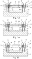
- Figs. 1a to 1f show a part of a first exemplary embodiment of a high lift system 2 in a schematic view.
- a high lift surface 4 is present, to which a first primary drive station 6, a second primary drive station 8, a first secondary unit 10 and a second secondary unit 12 are coupled.
- Each of the two primary drive stations 6 and 8 comprises a geared rotary actuator 14, which is coupled with a primary lever 16.
- the geared rotary actuators 14 comprise a shaft connection 18, coupled with a transmission shaft 20 being driven by a drive unit.
- This drive unit may be a central drive unit located at a clear distance to the arrangement shown or it may be an individual drive unit 22 indicated with dashed lines between the two secondary units 10 and 12.
- the geared rotary actuators 14 are provided with a torque, which is transferred into an extension motion or a retracting motion of the primary levers 16. Hence, by driving the transmission shaft 20, high lift surface 4 is extended or retracted.
- the secondary units 10 and 12 are passive and comprise a brake 24, which is coupled with a secondary lever 26 connected to the high lift surface 4. This may be conducted directly or through a gear having a certain gear ratio, depending on the expected loads.
- the brakes 24 may selectively be activated, such that a motion of the secondary lever 26, which follows the extension or retraction motion of high lift surface 4, may be arrested, which leads to an arrested high lift surface 4.
- the secondary units 10 and 12 comprise bearings 28, having a through-hole 30, through which the transmission shaft 20 extends. Consequently, the secondary units 10 and 12 are completely independent from the rotational motion of transmission shaft 20.
- the working principle of the arrangement of Fig. 1a is shown in Figures 1b to 1f .
- Fig. 1b the transfer of torque from the transmission shaft 20 to the primary drive stations 6 and 8 as well as the load path from these to the primary levers 16 and high lift surface 4 is shown.
- the load distribution during an extension or retraction motion of high lift surface 4 is demonstrated.
- the secondary units 10 and 12 are completely passive and simply follow the motion of the high lift surface 4.
- the brakes 24 in the secondary units 10 and 12 are activated, as seen in Fig. 1c , such that the position of the secondary levers 26 are arrested, which leads to arresting the high lift surface 4.
- the brakes 24 are continuously used during the normal operation of the aircraft, their operability state is always known to a central controller, such that no surprising, dormant failures may affect the safety operation.
- a possible failure of the transmission shaft 20 is demonstrated, indicated by a cross. Such a failure may be detected through monitoring rotational position of the transmission shaft 20 through e.g. a feedback position pickoff unit, which is not explicitly shown in these figures. If the rotational position of the transmission shaft 20 does not correspond to a desired position, it may be concluded that a failure of the transmission shaft 20 occurred. Hence, through activating the brakes 24 in the secondary units 10 and 12, the high lift surface 4 may be arrested in its momentary position reliably, as the secondary units 10 and 12 are completely independent from transmission shaft 20.
- Fig. 1e another possible failure is shown.
- the primary lever 16 from the second primary drive station 8 has lost a connection to the high lift surface 4.
- Such a failure may be detected through monitoring a load and/or a position and/or a speed or other suitable operation parameters on the primary levers 16 or a component coupled thereto.
- the high lift surface 4 may reliably arrested in its momentary position.
- the high lift surface 4 may be arrested through the remaining secondary unit 10 and the associated primary drive station 8.
- the two primary drive stations 34 and 36 are arranged at two distanced lateral positions on the high lift surface 4, while the secondary unit 38 is positioned between both primary drive stations 34 and 36.
- the additional brake 40 is located between the secondary unit 38 and the first primary drive station 34.
- the additional brake 40 may also be arranged at the space between the secondary unit 38 and the second primary drive station 36 or at a completely other position.
- Such a high lift system 32 may conduct the same operation as the high lift system 2 of the previous figures. However, as only a single secondary unit 38 is present, it should be positioned somewhere in the middle of the high lift surface 4 in order to be able to arrest the high lift surface 4 without risking a skewing motion and/or for reducing loads.
- the additional brake 40 is adapted for arresting a transmission shaft 42 that powers the primary drive stations 34 and 36. Hence, the high lift surface 4 may in this case be held by the primary drive stations 34 and 36 through the brake 40.
- a high lift system 44 is shown that comprises a transmission shaft 46 extending through primary drive stations 48 and 50 of two adjacent high lift surfaces 4, which are also connected to a single secondary unit 52 located approximately in the middle of the respective high lift surface 4.
- the setup of each high lift surface 4 is comparable to the setup shown in Fig. 2 .
- the additional brake 54 may be arranged between the innermost primary drive stations 48 and 50.
Description
- The invention relates to a high lift system for an aircraft, an aircraft having a wing and such a high lift system as well as to a method for moving a high lift surface relative to the wing of an aircraft.
- High lift systems of an aircraft allow to selectively increase the active surface area and the camber of a wing through extending high lift surfaces movably mounted thereon. These may include leading edge slats and trailing edge flaps. With extended high lift surfaces, the lift coefficient of the aircraft may drastically be increased for allowing low flight velocities, especially during descent and landing.
- In common commercial aircraft, a trailing edge flap system often comprises a central drive unit, which is also known as power control unit (PCU), for transferring rotational power to drive stations, which are distributed in the wing to move the trailing edge flaps. The transfer of rotational power is conducted through a continuous transmission shaft system that extends into the wing by reaching through all drive stations. A safety brake and a monitoring system are usually mechanically coupled with the transmission shaft. Further safety brakes and monitoring sensors are integrated in the drive unit.
- Some high lift systems may require dual load paths for the high lift surfaces. The drive stations often comprise geared rotary actuators, which may provide two independent drive or load paths, in order to increase the safety and preventing catastrophic failures under any circumstances. So far all dual load path solutions for a high lift system comprises duplicate drive elements which are synchronized with the primary drive elements. They require additional passive brakes and need to be tested for dormant failures. Furthermore, additional system brakes are required within the system.
-
GB 1 575 512 A -
EP 1 878 658 A2 discloses an actuator for actuating translation movement of a component, such as a horizontal stabilizer, relative to a structure of an aircraft. - It is an object of the invention to provide a dual load path solution for a high lift system of an aircraft, which allows a simple failure detection and eliminates maintenance tests.
- This object is met by a high lift system having the features of independent claim 1. Advantageous embodiments and further improvements may be gathered from the sub-claims and the following description.
- A high lift system for an aircraft is proposed, the high lift system comprising a drive unit, at least one high lift surface and at least one primary drive station, wherein each primary drive station has a shaft connection couplable with the drive unit and a primary lever couplable with one of the at least one high lift surface. The high lift system further comprises at least one secondary unit, each secondary unit having a secondary lever couplable with one of the at least one high lift surface. Each one of the at least one primary drive station is adapted for moving the respective primary lever on driving the shaft connection. Further, each of the at least one secondary unit comprises a selectively activatable brake, such that the secondary lever follows the motion of the one of the at least one high lift surface when the brake is deactivated and such that the secondary lever arrests the motion of the one of the at least one high lift surface when the brake is activated.
- It is therefore proposed to use a combination of primary drive stations and secondary units, wherein the primary drive station is dedicated for conducting the active motion of the respective high lift surface, i.e. the primary unit is a drive station. For this purpose, the primary drive station is couplable with the drive unit, which may be a central drive unit (PCU) residing in a center region of the aircraft. Such a primary drive station may comprise a geared rotary actuator, which is adapted for extending or retracting the primary lever to extend or retract the respective high lift surface.
- Contrary to this, the secondary unit is not directly coupled with the drive unit, but instead simply follows the motion of the respective high lift surface. This means, that the secondary lever, which is coupled to the respective high lift surface, conducts the same motion as the primary lever only through being connected to the respective high lift surface.
- A core aspect of this high lift system is the fact that the secondary unit is adapted for selectively arresting the passively conducted motion of the secondary lever by activating a brake residing in the secondary unit. This means that, for example, when the primary drive station stops its motion induced by the drive unit, the secondary unit may simply arrest the high lift surface in its momentary position. Consequently, even if there may be any failure in relation with the coupling between the primary drive station and the drive unit, the respective high lift surface position may reliably be maintained.
- The secondary unit not being coupled with the drive unit is advantageous as it is completely independent from any failure of a transmission shaft system or the drive unit and thereby clearly increases the safety of the high lift system without needing any central or additional brakes, depending on the number of secondary units installed in the system.
- In this regard it is noted that the brakes of the secondary units in such a high lift system may be used for several different situations. During the normal operation, the brake in a secondary unit allows to firmly arrest the extended or retracted high lift surface, such that a transmission shaft system and the primary drive stations do not need to continuously carry and/or compensate the air and mass loads on the high lift surfaces. Further, especially in case the high lift system is continuously monitored for failures, the individual secondary units may activate their brakes in case a failure is detected in the high lift system.
- Consequently, the secondary units provide a second load path for achieving a required level of redundancy. The design of the secondary drive units is simple and the complexity is low, leading to reduced manufacturing and maintenance costs.
- Another great advantage lies in the fact that the brakes in the secondary units are continuously used during normal operation, such that their function is always known throughout the normal operation of the aircraft. The danger of dormant failures may thereby drastically be reduced.
- In an advantageous embodiment, each one of the at least one high lift surface is coupled with two individual primary drive stations and at least one secondary unit. Coupling a high lift surface with two primary drive stations allows to extend and retract the high lift surface without any skew. However, a single secondary unit may be sufficient for providing an arresting function, especially when it is installed in a middle section of a high lift surface. Further, an additional system brake, which is couplable with both primary drive stations, may increase the reliability, while the system complexity is even more reduced.
- The use of two primary drive stations furthermore allows to drive the respective high lift surface individually, when at least one individual drive unit is coupled with the two primary drive stations . In this case, the secondary unit may reside somewhere between the two primary drive stations.
- In a still further advantageous embodiment, the drive unit is coupled with the at least one primary drive station by means of a transmission shaft, wherein the transmission shaft is coupled with a brake for arresting the rotation of the transmission shaft. Here, a reduction of the number of required secondary units may be accomplished, as the brake may provide for a backup brake or as a primary brake, in an alternating manner together with the brake in the secondary unit. The position of the brake may be arbitrarily chosen. If the transmission shaft belongs to a continuous transmission shaft train extending through the whole wing, the brake may be positioned basically anywhere on the transmission shaft. However, the brake may be arranged between two primary drive stations of the same high lift surface or of adjacent high lift surfaces.
- In a still further advantageous embodiment, each one of the at least one high lift surface is coupled with two primary drive stations and two secondary units. The installation of two secondary units allows to deal with a plurality of different failure situations only through these four devices. For example, in case one of the primary levers loses a connection to the respective primary drive station, a secondary unit may arrest the high lift surface, which is associated with the primary lever that has a failure. Also, after extending or retracting the respective high lift surface, the two secondary units allow for safely arrest the respective high lift surface in the momentary position without skewing.
- In a preferred embodiment, a secondary lever is positioned directly adjacent to a primary lever. Consequently, the load introduction positions of the primary and the secondary lever are almost the same and the forces on the high lift surface structure that arise in an arrested position hardly differs from the forces acting on it during the extension or retraction process.
- It may be particularly useful if a group of primary drive stations, the group comprising at least two primary drive stations, comprises an individual drive unit. The integration of a drive for a high lift surface allows a clear reduction of necessary transmission shaft lengths, as two primary drive stations of a high lift surface may be coupled to an individual drive unit, while the high lift surface is also coupled with one or two secondary units. Besides the ability to provide differential surface settings, it may also be possible to arrest jammed high lift surfaces and continuing a high lift surface operation with the remaining high lift surfaces. However, in these cases, a symmetrical high lift surface extension should be preferred.
- The high lift system preferably comprises a controller, which is coupled with sensors for detecting operation parameters, such as loads, speeds or positions, wherein the controller is configured for arresting a brake in at least one of the at least one secondary unit, in case the controller determines a failure in the system. The determination may be based on a comparison of desired operation parameters such as loads, speeds or positions, with the measured operation parameters. As explained previously, the secondary units not only provide the arresting of an associated high lift surface during normal operation, but also provide for arresting at least a part of the high lift system in any failure case. In this regard, loads may include forces on the primary or the secondary levers, which may be measured by strain gauges. For example, in case a secondary lever should be responsible for holding at least one edge of a high lift surface in a certain control situation and if a respective force sensor on this secondary lever does not measure any substantial force, the controller may determine that a failure occured in this load path. This determination may also be supported through measuring forces on a primary lever, which in this case may provide a substantial force even if the primary lever should not face a substantial load. It goes without saying, that this may also be conducted the other way round or in all possible combinations. As an alternative or additionally thereto, sensors may be provided for measuring positions, which may include position values delivered by a station position pickoff unit arranged in the primary drive stations and/or by feedback position pickoff units located in the drive unit. With these position information skew or jam cases are detectable. Through the use of such a plurality of sensors, the controller may always determine whether a predetermined operation of the high lift system is successful or whether a failure occurs. These failures may ultimately lead to a selective operation of a brake in at least one and preferably all secondary units in an affected region. However, in case a further brake outside any secondary unit is present, the controller may also be adapted for activating this particular additional brake, preferably in alternating cycles to the secondary unit. A regular application of all brakes is thereby ensured, which is advantageous, as dormant failures are prevented.
- At least one of the at least one primary drive station is coupled with the drive unit by means of a transmission shaft, wherein at least one of the at least one secondary unit comprises a through-hole, through which the transmission shaft extends. This allows for a compact setup and eliminates any changes in the extension direction of the transmission shaft and furthermore allows for basically the same dimensions of the primary drive stations and the secondary units.
- It is noted that the brake in the secondary unit may be coupled with the secondary lever through a gear having a certain gear ratio or it may be coupled with the secondary lever directly, depending on the expected load. The secondary unit needs to be able to freely move during an extension and a retraction motion of the respective high lift surface, until the brake is applied.
- The invention also relates to an aircraft having a wing and at least one such high lift system.
- In an advantageous embodiment, the aircraft comprises a central drive unit located in a wing root region, as well as a transmission shaft system extending into the wing and reaching through all primary drive stations.
- Still further, the invention also relates to a method for moving a high lift surface relative to a wing of an aircraft according to the steps of
independent claim 10. The method basically comprises the steps of driving at least one primary drive station coupled with a high lift surface by means of a primary lever, until a predetermined position is reached, and activating a brake in a secondary unit, which is coupled to the high lift surface by means of a secondary lever. - The method may further comprise detecting at least one operation parameter, in particular a load, speed or position of a primary drive station or a secondary unit and determining whether intended operation parameters are achieved and, in case of deviations between the intended operation parameters and the measured operation parameters arresting at least one of the at least one secondary unit.
- Further characteristics, advantages and application options of the present invention are disclosed in the following description of the exemplary embodiments in the figures.
-
Figs. 1a to 1f show a first exemplary embodiment in a schematic view with a number of different operation and failure cases. -
Fig. 2 shows a second exemplary embodiment in a schematic view. -
Fig. 3 shows a third exemplary embodiment comprising commonly driven high lift surfaces in a schematic view. -
Figs. 1a to 1f show a part of a first exemplary embodiment of ahigh lift system 2 in a schematic view. Here, ahigh lift surface 4 is present, to which a firstprimary drive station 6, a secondprimary drive station 8, a firstsecondary unit 10 and a secondsecondary unit 12 are coupled. - Each of the two
primary drive stations rotary actuator 14, which is coupled with aprimary lever 16. The gearedrotary actuators 14 comprise ashaft connection 18, coupled with atransmission shaft 20 being driven by a drive unit. This drive unit may be a central drive unit located at a clear distance to the arrangement shown or it may be anindividual drive unit 22 indicated with dashed lines between the twosecondary units - By driving the
transmission shaft 20, the gearedrotary actuators 14 are provided with a torque, which is transferred into an extension motion or a retracting motion of theprimary levers 16. Hence, by driving thetransmission shaft 20,high lift surface 4 is extended or retracted. - The
secondary units brake 24, which is coupled with asecondary lever 26 connected to thehigh lift surface 4. This may be conducted directly or through a gear having a certain gear ratio, depending on the expected loads. Thebrakes 24 may selectively be activated, such that a motion of thesecondary lever 26, which follows the extension or retraction motion ofhigh lift surface 4, may be arrested, which leads to an arrestedhigh lift surface 4. - In the example shown in
Fig. 1a , thesecondary units bearings 28, having a through-hole 30, through which thetransmission shaft 20 extends. Consequently, thesecondary units transmission shaft 20. The working principle of the arrangement ofFig. 1a is shown inFigures 1b to 1f . - In
Fig. 1b , the transfer of torque from thetransmission shaft 20 to theprimary drive stations primary levers 16 andhigh lift surface 4 is shown. In the depicted case, the load distribution during an extension or retraction motion ofhigh lift surface 4 is demonstrated. Here, thesecondary units high lift surface 4. - After reaching a predetermined position of the
high lift surface 4, thebrakes 24 in thesecondary units Fig. 1c , such that the position of thesecondary levers 26 are arrested, which leads to arresting thehigh lift surface 4. As thebrakes 24 are continuously used during the normal operation of the aircraft, their operability state is always known to a central controller, such that no surprising, dormant failures may affect the safety operation. - In
Fig. 1d , a possible failure of thetransmission shaft 20 is demonstrated, indicated by a cross. Such a failure may be detected through monitoring rotational position of thetransmission shaft 20 through e.g. a feedback position pickoff unit, which is not explicitly shown in these figures. If the rotational position of thetransmission shaft 20 does not correspond to a desired position, it may be concluded that a failure of thetransmission shaft 20 occurred. Hence, through activating thebrakes 24 in thesecondary units high lift surface 4 may be arrested in its momentary position reliably, as thesecondary units transmission shaft 20. - In
Fig. 1e , another possible failure is shown. Here, theprimary lever 16 from the secondprimary drive station 8 has lost a connection to thehigh lift surface 4. Such a failure may be detected through monitoring a load and/or a position and/or a speed or other suitable operation parameters on theprimary levers 16 or a component coupled thereto. Through arresting thebrakes 24 in thesecondary units high lift surface 4 may reliably arrested in its momentary position. - However, in case a secondary lever loses connection to the
high lift surface 4, as shown inFig. 1f , thehigh lift surface 4 may be arrested through the remainingsecondary unit 10 and the associatedprimary drive station 8. - Another exemplary embodiment of a part of a
high lift system 32 having twoprimary drive stations secondary unit 38 and anadditional brake 40. The twoprimary drive stations high lift surface 4, while thesecondary unit 38 is positioned between bothprimary drive stations additional brake 40 is located between thesecondary unit 38 and the firstprimary drive station 34. However, theadditional brake 40 may also be arranged at the space between thesecondary unit 38 and the secondprimary drive station 36 or at a completely other position. - Such a
high lift system 32 may conduct the same operation as thehigh lift system 2 of the previous figures. However, as only a singlesecondary unit 38 is present, it should be positioned somewhere in the middle of thehigh lift surface 4 in order to be able to arrest thehigh lift surface 4 without risking a skewing motion and/or for reducing loads. For failure cases of thesecondary unit 38 itself, theadditional brake 40 is adapted for arresting atransmission shaft 42 that powers theprimary drive stations high lift surface 4 may in this case be held by theprimary drive stations brake 40. - In a still further embodiment, a
high lift system 44 is shown that comprises atransmission shaft 46 extending throughprimary drive stations high lift surfaces 4, which are also connected to a singlesecondary unit 52 located approximately in the middle of the respectivehigh lift surface 4. Hence, the setup of eachhigh lift surface 4 is comparable to the setup shown inFig. 2 . As two adjacenthigh lift surfaces 4 are driven by acommon transmission shaft 46, only oneadditional brake 54 is necessary for any failure case of any of thesecondary units 52. Theadditional brake 54 may be arranged between the innermostprimary drive stations - In addition, it should be pointed out that "comprising" does not exclude other elements or steps, and "a" or "an" does not exclude a plural number. Furthermore, it should be pointed out that characteristics or steps which have been described with reference to one of the above exemplary embodiments can also be used in combination with other characteristics or steps of other exemplary embodiments described above. Reference characters in the claims are not to be interpreted as limitations.
Claims (11)
- High lift system (2, 32, 44) for an aircraft, comprising- at least one drive unit (22),- at least one high lift surface (4),- at least one primary drive station (6, 8, 34, 36, 48, 50), each primary drive station (6, 8, 34, 36, 48, 50) having a shaft connection (18) coupled with the at least one drive unit (22) and a primary lever (16) coupled with one of the at least one high lift surface (4),- at least one secondary unit (10, 12, 38, 52), each secondary unit (10, 12, 38, 52) having a secondary lever (26) coupled with one of the at least one high lift surface (4),wherein each one of the at least one primary drive station (6, 8, 34, 36, 48, 50) is adapted for moving the respective primary lever (16) on driving the shaft connection (18), and
wherein each one of the at least one secondary unit (10, 12, 38, 52) comprises a selectively activatable brake (24), such that the secondary lever (26) follows the motion of the one of the at least one high lift surface (4) when the brake (24) is deactivated and such that the secondary lever (26) arrests the motion of the one of the at least one high lift surface (4) when the brake (24) is activated,
characterized in that at least one of the at least one primary drive station (6, 8, 34, 36, 48, 50) is coupled with the drive unit (22) by means of a transmission shaft (20, 42, 46),
wherein at least one of the at least one secondary unit (10, 12, 38, 52) comprises a through-hole (30), through which the transmission shaft (20, 42, 46) extends. - High lift (2, 32, 44) system of claim 1,
wherein each one of the at least one high lift surface (4) is coupled with two individual primary drive stations (6, 8, 34, 36, 48, 50) and at least one secondary unit (10, 12, 38, 52). - High lift system (2, 32, 44) of claim 1 or 2,
wherein the transmission shaft (20, 42, 46) is coupled with a brake (40, 54) for arresting the rotation of the transmission shaft (20, 42, 46). - High lift system (2, 32, 44) of any of the previous claims,
wherein each one of the at least one high lift surface (4) is coupled with two primary drive stations (6, 8, 34, 36, 48, 50) and two secondary units (10, 12, 38, 52). - High lift system (2, 32, 44) of any of the previous claims,
wherein a secondary lever (26) is positioned directly adjacent to a primary lever (16). - High lift system (2, 32, 44) of any of the previous claims,
wherein a group of primary drive stations (6, 8, 34, 36, 48, 50), the group comprising at least two primary drive stations (6, 8, 34, 36, 48, 50), comprises an individual drive unit (22). - High lift system (2, 32, 44) of any of the previous claims,
further comprising a controller, which is coupled with sensors for detecting at least one operation parameter in the at least one primary drive station (6, 8, 34, 36, 48, 50) or in the at least one secondary unit (10, 12, 38, 52),
wherein the controller is adapted for arresting a brake (24) in at least one of the at least one secondary unit (10, 12, 38, 52), in case the controller determines a mechanical failure based on a comparison of at least one desired operation parameter with the measured at least one operation parameter. - Aircraft, having a wing and at least one high lift system (2, 32, 44) of any of the claims 1 to 7.
- Aircraft of claim 8, wherein the at least one drive unit (22) is a central drive unit located in a wing root region and wherein the transmission shaft (20, 42, 46) extends into the wing and reaches through all primary drive stations (6, 8, 34, 36, 48, 50) of the high lift system (2, 32, 44).
- Method for moving a high lift surface (4) relative to a wing of an aircraft, the method comprising the steps of- driving at least one primary drive station (6, 8, 34, 36, 48, 50), each primary drive station (6, 8, 34, 36, 48, 50) having a shaft connection (18) coupled with at least one drive unit (22) through a transmission shaft (20, 42, 46), and coupled with a high lift surface (4) by means of a primary lever (16), by driving the shaft connection (18), until a predetermined position is reached, and- activating a brake (24) in at least one secondary unit (10, 12, 38, 52), each secondary unit (10, 12, 38, 52) being coupled to the high lift surface by means of a secondary lever (26), wherein each one of the at least one secondary unit (10, 12, 38, 52) comprises a selectively activatable brake (24), such that the secondary lever (26) arrests the motion of the one of the at least one high lift surface (4) when the brake (24) is activated, and- deactivating the brake (24) in the at least one secondary unit (10, 12, 38, 52), such that the secondary lever (26) follows the motion of the one of the at least one high lift surface (4) when the brake (24) is deactivated,wherein at least one of the at least one secondary unit (10, 12, 38, 52) comprises a through-hole (30), through which the transmission shaft (20, 42, 46) extends.
- Method of claim 10, further comprising- detecting at least one operation parameter of a primary drive station (6, 8, 34, 36, 48, 50) or a secondary unit (10, 12, 38, 52),- determining whether at least one intended operation parameter is achieved, and,- arresting at least one of the at least one secondary unit (10, 12, 38, 52) in case of deviations between the at least one intended operation parameter and the measured at least one operation parameter.
Priority Applications (3)
| Application Number | Priority Date | Filing Date | Title |
|---|---|---|---|
| EP14171960.9A EP2955104B1 (en) | 2014-06-11 | 2014-06-11 | System and method for moving a high lift surface relative to the wing of an aircraft |
| US14/719,864 US9771144B2 (en) | 2014-06-11 | 2015-05-22 | High lift system for an aircraft, aircraft having a wing and a high lift system and method for moving a high lift surface relative to the wing of an aircraft |
| CN201510316297.7A CN105314093B (en) | 2014-06-11 | 2015-06-10 | High-lift system, aircraft and make lift-rising surface relative to the method that wing is moved |
Applications Claiming Priority (1)
| Application Number | Priority Date | Filing Date | Title |
|---|---|---|---|
| EP14171960.9A EP2955104B1 (en) | 2014-06-11 | 2014-06-11 | System and method for moving a high lift surface relative to the wing of an aircraft |
Publications (2)
| Publication Number | Publication Date |
|---|---|
| EP2955104A1 EP2955104A1 (en) | 2015-12-16 |
| EP2955104B1 true EP2955104B1 (en) | 2017-08-09 |
Family
ID=50927977
Family Applications (1)
| Application Number | Title | Priority Date | Filing Date |
|---|---|---|---|
| EP14171960.9A Active EP2955104B1 (en) | 2014-06-11 | 2014-06-11 | System and method for moving a high lift surface relative to the wing of an aircraft |
Country Status (3)
| Country | Link |
|---|---|
| US (1) | US9771144B2 (en) |
| EP (1) | EP2955104B1 (en) |
| CN (1) | CN105314093B (en) |
Families Citing this family (16)
| Publication number | Priority date | Publication date | Assignee | Title |
|---|---|---|---|---|
| US9950782B2 (en) * | 2014-10-31 | 2018-04-24 | The Boeing Company | Methods and apparatus for integrating rotary actuators in flight control systems |
| EP3037346B1 (en) * | 2014-12-22 | 2018-10-24 | Airbus Operations GmbH | Method for testing a component in a high lift system of an aircraft |
| EP3037347B1 (en) * | 2014-12-22 | 2019-02-06 | Airbus Operations GmbH | Method for determining a state of a component in a high lift system of an aircraft |
| US10336437B2 (en) * | 2017-05-05 | 2019-07-02 | Hamilton Sundstrand Corporation | Method to measure aircraft high-lift system brake response time |
| CN107226218B (en) * | 2017-08-15 | 2019-05-10 | 西安航空制动科技有限公司 | The test method of airplane brake system combined stress |
| CN107544469A (en) * | 2017-09-25 | 2018-01-05 | 中国航空工业集团公司西安飞机设计研究所 | A kind of automatic winged control closed loop test system with configuration |
| US10882604B2 (en) | 2018-01-18 | 2021-01-05 | The Boeing Company | Distributed trailing edge wing flap systems |
| US10948365B2 (en) * | 2018-01-26 | 2021-03-16 | The Boeing Company | Force balance sensor and method therefor |
| US10882603B2 (en) | 2018-03-20 | 2021-01-05 | The Boeing Company | Distributed trailing edge wing flap systems |
| US10829203B2 (en) | 2018-04-06 | 2020-11-10 | The Boeing Company | Distributed trailing edge wing flap systems |
| US11214353B2 (en) * | 2018-06-01 | 2022-01-04 | Airbus Operations Gmbh | Wing arrangement for an aircraft and aircraft |
| US11027824B2 (en) * | 2018-09-05 | 2021-06-08 | The Boeing Company | Distributed trailing edge wing flap systems |
| US10926867B2 (en) | 2018-09-10 | 2021-02-23 | The Boeing Company | Distributed trailing edge wing flap systems |
| US11873092B2 (en) * | 2020-12-16 | 2024-01-16 | The Boeing Company | Trim actuators for horizontal stabilizers and methods of controlling horizontal stabilizers |
| EP4112450A1 (en) * | 2021-06-30 | 2023-01-04 | Airbus Operations GmbH | Wing for an aircraft |
| CN114415647B (en) * | 2022-03-29 | 2022-07-15 | 西安羚控电子科技有限公司 | Fault injection device and fault injection method for high-lift system |
Family Cites Families (15)
| Publication number | Priority date | Publication date | Assignee | Title |
|---|---|---|---|---|
| GB1575512A (en) * | 1976-03-25 | 1980-09-24 | Lucas Industries Ltd | Braking device for use in a remote actuation system |
| US4498647A (en) * | 1982-03-15 | 1985-02-12 | Mcdonnel Douglas Corporation | Surface hold-down mechanism |
| US4688744A (en) * | 1982-09-03 | 1987-08-25 | Sundstrand Corporation | Jam tolerant rotary actuation system |
| DE3505839A1 (en) * | 1985-02-20 | 1986-08-21 | Messerschmitt-Bölkow-Blohm GmbH, 2800 Bremen | Failure protection device for flap systems on aircraft mainplanes |
| US4779822A (en) * | 1986-05-23 | 1988-10-25 | Sundstrand Corporation | Actuator system |
| US4909364A (en) * | 1988-05-12 | 1990-03-20 | Sundstrand Corporation | Latching failure detection mechanism for rotary drive systems |
| DE10313728B4 (en) * | 2003-03-27 | 2011-07-21 | Airbus Operations GmbH, 21129 | Flap system on the wing of a fixed-wing aircraft |
| DE10326799B3 (en) * | 2003-06-13 | 2004-12-16 | Airbus Deutschland Gmbh | Device for actuating flap elements on the wings of an aircraft |
| DE10361891A1 (en) * | 2003-12-23 | 2005-08-04 | Airbus Deutschland Gmbh | Device for controlling and adjusting flaps on aircraft wings |
| DE102004047008A1 (en) * | 2004-09-28 | 2006-03-30 | Liebherr-Aerospace Lindenberg Gmbh | Device for adjusting aircraft altitude fins |
| US20080203223A1 (en) * | 2006-06-22 | 2008-08-28 | Cyrot Luc P | Aircraft stabilizer actuator |
| DE102007021748B4 (en) * | 2007-05-09 | 2019-12-12 | Liebherr-Aerospace Lindenberg Gmbh | Drive system for a vault-variable aircraft wing |
| US7878459B2 (en) * | 2007-06-29 | 2011-02-01 | The Boeing Company | Aircraft systems with shape memory alloy (SMA) actuators, and associated methods |
| DE102008022092A1 (en) * | 2008-05-05 | 2009-11-19 | Airbus Deutschland Gmbh | Fault-tolerant control system for adjusting the flaps of an aircraft with adjustable kinematics with a fixed axis of rotation |
| DE102012020820B4 (en) * | 2012-10-23 | 2022-03-17 | Liebherr-Aerospace Lindenberg Gmbh | Differential speed dependent brake |
-
2014
- 2014-06-11 EP EP14171960.9A patent/EP2955104B1/en active Active
-
2015
- 2015-05-22 US US14/719,864 patent/US9771144B2/en active Active
- 2015-06-10 CN CN201510316297.7A patent/CN105314093B/en active Active
Also Published As
| Publication number | Publication date |
|---|---|
| EP2955104A1 (en) | 2015-12-16 |
| CN105314093A (en) | 2016-02-10 |
| US20150360769A1 (en) | 2015-12-17 |
| US9771144B2 (en) | 2017-09-26 |
| CN105314093B (en) | 2017-09-29 |
Similar Documents
| Publication | Publication Date | Title |
|---|---|---|
| EP2955104B1 (en) | System and method for moving a high lift surface relative to the wing of an aircraft | |
| EP2803584B1 (en) | Actuation system for flight control surface | |
| US8746614B2 (en) | System for actuating at least one positioning flap of an aircraft and a method for monitoring the system | |
| EP2695810B1 (en) | Drive system for control surfaces of an aircraft | |
| US5743490A (en) | Flap/slat actuation system for an aircraft | |
| US6824099B1 (en) | Brake systems for aircraft wing flaps and other control surfaces | |
| EP2783988B1 (en) | Monitoring of high-lift systems for aircraft | |
| US8814082B2 (en) | Aircraft high lift system and method for determining an operating condition of an aircraft high lift system | |
| US8746625B2 (en) | Flap adjusting system of an aircraft with a regulating flap | |
| US9108724B2 (en) | Adjustment system of an aeroplane with an adjustable flap | |
| EP3037346B1 (en) | Method for testing a component in a high lift system of an aircraft | |
| US8132763B2 (en) | Aircraft highlift system | |
| US8868261B2 (en) | Monitoring device for an actuation system of an aircraft, actuation system and method for reconfiguring the actuation system | |
| EP3037347B1 (en) | Method for determining a state of a component in a high lift system of an aircraft | |
| US9261150B2 (en) | Drive system for a high lift system of an aircraft and method for detecting a misalignment between a transmission shaft and an opening in a drive system for a high lift system of an aircraft | |
| CN111372852A (en) | System and method for actuating high-lift flight control surfaces | |
| US11067496B2 (en) | System for detecting a mechanical fault in a rotating shaft | |
| US11383822B2 (en) | Distributed active brakes for aircraft high-lift devices | |
| EP4282766A1 (en) | High lift skew system |
Legal Events
| Date | Code | Title | Description |
|---|---|---|---|
| PUAI | Public reference made under article 153(3) epc to a published international application that has entered the european phase |
Free format text: ORIGINAL CODE: 0009012 |
|
| AK | Designated contracting states |
Kind code of ref document: A1 Designated state(s): AL AT BE BG CH CY CZ DE DK EE ES FI FR GB GR HR HU IE IS IT LI LT LU LV MC MK MT NL NO PL PT RO RS SE SI SK SM TR |
|
| AX | Request for extension of the european patent |
Extension state: BA ME |
|
| 17P | Request for examination filed |
Effective date: 20160615 |
|
| RBV | Designated contracting states (corrected) |
Designated state(s): AL AT BE BG CH CY CZ DE DK EE ES FI FR GB GR HR HU IE IS IT LI LT LU LV MC MK MT NL NO PL PT RO RS SE SI SK SM TR |
|
| GRAP | Despatch of communication of intention to grant a patent |
Free format text: ORIGINAL CODE: EPIDOSNIGR1 |
|
| STAA | Information on the status of an ep patent application or granted ep patent |
Free format text: STATUS: GRANT OF PATENT IS INTENDED |
|
| RIC1 | Information provided on ipc code assigned before grant |
Ipc: B64C 13/28 20060101ALI20161206BHEP Ipc: B64C 13/42 20060101ALI20161206BHEP Ipc: B64C 3/50 20060101ALN20161206BHEP Ipc: B64C 13/50 20060101ALN20161206BHEP Ipc: B64C 9/02 20060101AFI20161206BHEP Ipc: B64D 45/00 20060101ALN20161206BHEP |
|
| INTG | Intention to grant announced |
Effective date: 20170110 |
|
| GRAS | Grant fee paid |
Free format text: ORIGINAL CODE: EPIDOSNIGR3 |
|
| GRAA | (expected) grant |
Free format text: ORIGINAL CODE: 0009210 |
|
| STAA | Information on the status of an ep patent application or granted ep patent |
Free format text: STATUS: THE PATENT HAS BEEN GRANTED |
|
| AK | Designated contracting states |
Kind code of ref document: B1 Designated state(s): AL AT BE BG CH CY CZ DE DK EE ES FI FR GB GR HR HU IE IS IT LI LT LU LV MC MK MT NL NO PL PT RO RS SE SI SK SM TR |
|
| REG | Reference to a national code |
Ref country code: GB Ref legal event code: FG4D |
|
| REG | Reference to a national code |
Ref country code: CH Ref legal event code: EP Ref country code: AT Ref legal event code: REF Ref document number: 916491 Country of ref document: AT Kind code of ref document: T Effective date: 20170815 |
|
| REG | Reference to a national code |
Ref country code: IE Ref legal event code: FG4D |
|
| REG | Reference to a national code |
Ref country code: DE Ref legal event code: R096 Ref document number: 602014012759 Country of ref document: DE |
|
| REG | Reference to a national code |
Ref country code: NL Ref legal event code: MP Effective date: 20170809 |
|
| REG | Reference to a national code |
Ref country code: LT Ref legal event code: MG4D |
|
| REG | Reference to a national code |
Ref country code: AT Ref legal event code: MK05 Ref document number: 916491 Country of ref document: AT Kind code of ref document: T Effective date: 20170809 |
|
| PG25 | Lapsed in a contracting state [announced via postgrant information from national office to epo] |
Ref country code: NL Free format text: LAPSE BECAUSE OF FAILURE TO SUBMIT A TRANSLATION OF THE DESCRIPTION OR TO PAY THE FEE WITHIN THE PRESCRIBED TIME-LIMIT Effective date: 20170809 Ref country code: HR Free format text: LAPSE BECAUSE OF FAILURE TO SUBMIT A TRANSLATION OF THE DESCRIPTION OR TO PAY THE FEE WITHIN THE PRESCRIBED TIME-LIMIT Effective date: 20170809 Ref country code: SE Free format text: LAPSE BECAUSE OF FAILURE TO SUBMIT A TRANSLATION OF THE DESCRIPTION OR TO PAY THE FEE WITHIN THE PRESCRIBED TIME-LIMIT Effective date: 20170809 Ref country code: LT Free format text: LAPSE BECAUSE OF FAILURE TO SUBMIT A TRANSLATION OF THE DESCRIPTION OR TO PAY THE FEE WITHIN THE PRESCRIBED TIME-LIMIT Effective date: 20170809 Ref country code: NO Free format text: LAPSE BECAUSE OF FAILURE TO SUBMIT A TRANSLATION OF THE DESCRIPTION OR TO PAY THE FEE WITHIN THE PRESCRIBED TIME-LIMIT Effective date: 20171109 Ref country code: AT Free format text: LAPSE BECAUSE OF FAILURE TO SUBMIT A TRANSLATION OF THE DESCRIPTION OR TO PAY THE FEE WITHIN THE PRESCRIBED TIME-LIMIT Effective date: 20170809 Ref country code: FI Free format text: LAPSE BECAUSE OF FAILURE TO SUBMIT A TRANSLATION OF THE DESCRIPTION OR TO PAY THE FEE WITHIN THE PRESCRIBED TIME-LIMIT Effective date: 20170809 |
|
| PG25 | Lapsed in a contracting state [announced via postgrant information from national office to epo] |
Ref country code: PL Free format text: LAPSE BECAUSE OF FAILURE TO SUBMIT A TRANSLATION OF THE DESCRIPTION OR TO PAY THE FEE WITHIN THE PRESCRIBED TIME-LIMIT Effective date: 20170809 Ref country code: RS Free format text: LAPSE BECAUSE OF FAILURE TO SUBMIT A TRANSLATION OF THE DESCRIPTION OR TO PAY THE FEE WITHIN THE PRESCRIBED TIME-LIMIT Effective date: 20170809 Ref country code: BG Free format text: LAPSE BECAUSE OF FAILURE TO SUBMIT A TRANSLATION OF THE DESCRIPTION OR TO PAY THE FEE WITHIN THE PRESCRIBED TIME-LIMIT Effective date: 20171109 Ref country code: LV Free format text: LAPSE BECAUSE OF FAILURE TO SUBMIT A TRANSLATION OF THE DESCRIPTION OR TO PAY THE FEE WITHIN THE PRESCRIBED TIME-LIMIT Effective date: 20170809 Ref country code: ES Free format text: LAPSE BECAUSE OF FAILURE TO SUBMIT A TRANSLATION OF THE DESCRIPTION OR TO PAY THE FEE WITHIN THE PRESCRIBED TIME-LIMIT Effective date: 20170809 Ref country code: IS Free format text: LAPSE BECAUSE OF FAILURE TO SUBMIT A TRANSLATION OF THE DESCRIPTION OR TO PAY THE FEE WITHIN THE PRESCRIBED TIME-LIMIT Effective date: 20171209 Ref country code: GR Free format text: LAPSE BECAUSE OF FAILURE TO SUBMIT A TRANSLATION OF THE DESCRIPTION OR TO PAY THE FEE WITHIN THE PRESCRIBED TIME-LIMIT Effective date: 20171110 |
|
| PG25 | Lapsed in a contracting state [announced via postgrant information from national office to epo] |
Ref country code: CZ Free format text: LAPSE BECAUSE OF FAILURE TO SUBMIT A TRANSLATION OF THE DESCRIPTION OR TO PAY THE FEE WITHIN THE PRESCRIBED TIME-LIMIT Effective date: 20170809 Ref country code: DK Free format text: LAPSE BECAUSE OF FAILURE TO SUBMIT A TRANSLATION OF THE DESCRIPTION OR TO PAY THE FEE WITHIN THE PRESCRIBED TIME-LIMIT Effective date: 20170809 Ref country code: RO Free format text: LAPSE BECAUSE OF FAILURE TO SUBMIT A TRANSLATION OF THE DESCRIPTION OR TO PAY THE FEE WITHIN THE PRESCRIBED TIME-LIMIT Effective date: 20170809 |
|
| REG | Reference to a national code |
Ref country code: DE Ref legal event code: R097 Ref document number: 602014012759 Country of ref document: DE |
|
| PG25 | Lapsed in a contracting state [announced via postgrant information from national office to epo] |
Ref country code: SM Free format text: LAPSE BECAUSE OF FAILURE TO SUBMIT A TRANSLATION OF THE DESCRIPTION OR TO PAY THE FEE WITHIN THE PRESCRIBED TIME-LIMIT Effective date: 20170809 Ref country code: IT Free format text: LAPSE BECAUSE OF FAILURE TO SUBMIT A TRANSLATION OF THE DESCRIPTION OR TO PAY THE FEE WITHIN THE PRESCRIBED TIME-LIMIT Effective date: 20170809 Ref country code: SK Free format text: LAPSE BECAUSE OF FAILURE TO SUBMIT A TRANSLATION OF THE DESCRIPTION OR TO PAY THE FEE WITHIN THE PRESCRIBED TIME-LIMIT Effective date: 20170809 Ref country code: EE Free format text: LAPSE BECAUSE OF FAILURE TO SUBMIT A TRANSLATION OF THE DESCRIPTION OR TO PAY THE FEE WITHIN THE PRESCRIBED TIME-LIMIT Effective date: 20170809 |
|
| PLBE | No opposition filed within time limit |
Free format text: ORIGINAL CODE: 0009261 |
|
| STAA | Information on the status of an ep patent application or granted ep patent |
Free format text: STATUS: NO OPPOSITION FILED WITHIN TIME LIMIT |
|
| REG | Reference to a national code |
Ref country code: FR Ref legal event code: PLFP Year of fee payment: 5 |
|
| 26N | No opposition filed |
Effective date: 20180511 |
|
| PG25 | Lapsed in a contracting state [announced via postgrant information from national office to epo] |
Ref country code: SI Free format text: LAPSE BECAUSE OF FAILURE TO SUBMIT A TRANSLATION OF THE DESCRIPTION OR TO PAY THE FEE WITHIN THE PRESCRIBED TIME-LIMIT Effective date: 20170809 |
|
| REG | Reference to a national code |
Ref country code: CH Ref legal event code: PL |
|
| REG | Reference to a national code |
Ref country code: BE Ref legal event code: MM Effective date: 20180630 |
|
| REG | Reference to a national code |
Ref country code: IE Ref legal event code: MM4A |
|
| PG25 | Lapsed in a contracting state [announced via postgrant information from national office to epo] |
Ref country code: LU Free format text: LAPSE BECAUSE OF NON-PAYMENT OF DUE FEES Effective date: 20180611 Ref country code: MC Free format text: LAPSE BECAUSE OF FAILURE TO SUBMIT A TRANSLATION OF THE DESCRIPTION OR TO PAY THE FEE WITHIN THE PRESCRIBED TIME-LIMIT Effective date: 20170809 |
|
| PG25 | Lapsed in a contracting state [announced via postgrant information from national office to epo] |
Ref country code: IE Free format text: LAPSE BECAUSE OF NON-PAYMENT OF DUE FEES Effective date: 20180611 Ref country code: LI Free format text: LAPSE BECAUSE OF NON-PAYMENT OF DUE FEES Effective date: 20180630 Ref country code: CH Free format text: LAPSE BECAUSE OF NON-PAYMENT OF DUE FEES Effective date: 20180630 |
|
| PG25 | Lapsed in a contracting state [announced via postgrant information from national office to epo] |
Ref country code: BE Free format text: LAPSE BECAUSE OF NON-PAYMENT OF DUE FEES Effective date: 20180630 |
|
| PG25 | Lapsed in a contracting state [announced via postgrant information from national office to epo] |
Ref country code: MT Free format text: LAPSE BECAUSE OF NON-PAYMENT OF DUE FEES Effective date: 20180611 |
|
| PG25 | Lapsed in a contracting state [announced via postgrant information from national office to epo] |
Ref country code: TR Free format text: LAPSE BECAUSE OF FAILURE TO SUBMIT A TRANSLATION OF THE DESCRIPTION OR TO PAY THE FEE WITHIN THE PRESCRIBED TIME-LIMIT Effective date: 20170809 |
|
| PG25 | Lapsed in a contracting state [announced via postgrant information from national office to epo] |
Ref country code: PT Free format text: LAPSE BECAUSE OF FAILURE TO SUBMIT A TRANSLATION OF THE DESCRIPTION OR TO PAY THE FEE WITHIN THE PRESCRIBED TIME-LIMIT Effective date: 20170809 |
|
| PG25 | Lapsed in a contracting state [announced via postgrant information from national office to epo] |
Ref country code: HU Free format text: LAPSE BECAUSE OF FAILURE TO SUBMIT A TRANSLATION OF THE DESCRIPTION OR TO PAY THE FEE WITHIN THE PRESCRIBED TIME-LIMIT; INVALID AB INITIO Effective date: 20140611 Ref country code: CY Free format text: LAPSE BECAUSE OF FAILURE TO SUBMIT A TRANSLATION OF THE DESCRIPTION OR TO PAY THE FEE WITHIN THE PRESCRIBED TIME-LIMIT Effective date: 20170809 Ref country code: MK Free format text: LAPSE BECAUSE OF NON-PAYMENT OF DUE FEES Effective date: 20170809 |
|
| PG25 | Lapsed in a contracting state [announced via postgrant information from national office to epo] |
Ref country code: AL Free format text: LAPSE BECAUSE OF FAILURE TO SUBMIT A TRANSLATION OF THE DESCRIPTION OR TO PAY THE FEE WITHIN THE PRESCRIBED TIME-LIMIT Effective date: 20170809 |
|
| PGFP | Annual fee paid to national office [announced via postgrant information from national office to epo] |
Ref country code: FR Payment date: 20230628 Year of fee payment: 10 Ref country code: DE Payment date: 20230620 Year of fee payment: 10 |
|
| PGFP | Annual fee paid to national office [announced via postgrant information from national office to epo] |
Ref country code: GB Payment date: 20230622 Year of fee payment: 10 |