EP3037346B1 - Method for testing a component in a high lift system of an aircraft - Google Patents
Method for testing a component in a high lift system of an aircraft Download PDFInfo
- Publication number
- EP3037346B1 EP3037346B1 EP14199892.2A EP14199892A EP3037346B1 EP 3037346 B1 EP3037346 B1 EP 3037346B1 EP 14199892 A EP14199892 A EP 14199892A EP 3037346 B1 EP3037346 B1 EP 3037346B1
- Authority
- EP
- European Patent Office
- Prior art keywords
- brake
- high lift
- hydraulic motor
- control unit
- hydraulic
- Prior art date
- Legal status (The legal status is an assumption and is not a legal conclusion. Google has not performed a legal analysis and makes no representation as to the accuracy of the status listed.)
- Active
Links
- 238000000034 method Methods 0.000 title claims description 34
- 238000012360 testing method Methods 0.000 title claims description 14
- 230000033001 locomotion Effects 0.000 claims description 27
- 230000005540 biological transmission Effects 0.000 claims description 18
- 230000007935 neutral effect Effects 0.000 claims description 11
- 230000003213 activating effect Effects 0.000 claims description 8
- 230000009471 action Effects 0.000 description 6
- 238000006073 displacement reaction Methods 0.000 description 5
- 210000001550 testis Anatomy 0.000 description 4
- 230000004913 activation Effects 0.000 description 2
- 230000008901 benefit Effects 0.000 description 2
- 238000013461 design Methods 0.000 description 2
- 238000010586 diagram Methods 0.000 description 2
- 230000006870 function Effects 0.000 description 2
- 238000012423 maintenance Methods 0.000 description 2
- 230000007246 mechanism Effects 0.000 description 2
- 238000012544 monitoring process Methods 0.000 description 2
- 230000008569 process Effects 0.000 description 2
- 230000002159 abnormal effect Effects 0.000 description 1
- 230000008859 change Effects 0.000 description 1
- 238000006243 chemical reaction Methods 0.000 description 1
- 230000008878 coupling Effects 0.000 description 1
- 238000010168 coupling process Methods 0.000 description 1
- 238000005859 coupling reaction Methods 0.000 description 1
- 230000007547 defect Effects 0.000 description 1
- 238000001514 detection method Methods 0.000 description 1
- 230000000694 effects Effects 0.000 description 1
- 239000012530 fluid Substances 0.000 description 1
- 230000003116 impacting effect Effects 0.000 description 1
- 230000006872 improvement Effects 0.000 description 1
- 230000000977 initiatory effect Effects 0.000 description 1
- 230000004048 modification Effects 0.000 description 1
- 238000012986 modification Methods 0.000 description 1
- 238000004513 sizing Methods 0.000 description 1
- 230000001360 synchronised effect Effects 0.000 description 1
Images

Classifications
-
- B—PERFORMING OPERATIONS; TRANSPORTING
- B64—AIRCRAFT; AVIATION; COSMONAUTICS
- B64D—EQUIPMENT FOR FITTING IN OR TO AIRCRAFT; FLIGHT SUITS; PARACHUTES; ARRANGEMENTS OR MOUNTING OF POWER PLANTS OR PROPULSION TRANSMISSIONS IN AIRCRAFT
- B64D45/00—Aircraft indicators or protectors not otherwise provided for
-
- B—PERFORMING OPERATIONS; TRANSPORTING
- B64—AIRCRAFT; AVIATION; COSMONAUTICS
- B64C—AEROPLANES; HELICOPTERS
- B64C13/00—Control systems or transmitting systems for actuating flying-control surfaces, lift-increasing flaps, air brakes, or spoilers
- B64C13/24—Transmitting means
- B64C13/38—Transmitting means with power amplification
- B64C13/40—Transmitting means with power amplification using fluid pressure
-
- B—PERFORMING OPERATIONS; TRANSPORTING
- B64—AIRCRAFT; AVIATION; COSMONAUTICS
- B64F—GROUND OR AIRCRAFT-CARRIER-DECK INSTALLATIONS SPECIALLY ADAPTED FOR USE IN CONNECTION WITH AIRCRAFT; DESIGNING, MANUFACTURING, ASSEMBLING, CLEANING, MAINTAINING OR REPAIRING AIRCRAFT, NOT OTHERWISE PROVIDED FOR; HANDLING, TRANSPORTING, TESTING OR INSPECTING AIRCRAFT COMPONENTS, NOT OTHERWISE PROVIDED FOR
- B64F5/00—Designing, manufacturing, assembling, cleaning, maintaining or repairing aircraft, not otherwise provided for; Handling, transporting, testing or inspecting aircraft components, not otherwise provided for
- B64F5/60—Testing or inspecting aircraft components or systems
-
- B—PERFORMING OPERATIONS; TRANSPORTING
- B64—AIRCRAFT; AVIATION; COSMONAUTICS
- B64C—AEROPLANES; HELICOPTERS
- B64C9/00—Adjustable control surfaces or members, e.g. rudders
- B64C9/32—Air braking surfaces
- B64C9/323—Air braking surfaces associated with wings
Definitions
- the invention relates to a method for testing a component in a high lift system of an aircraft, a high lift system of an aircraft as well as an aircraft having a wing, a hydraulic network and at least one such high lift system.
- high lift systems of commercial and military aircraft are powered by a centralized drive, also known as power control unit (PCU), which is mounted in a central region of the fuselage and is controllable through a computerized control.
- the PCU is coupled with a torque shaft system, also known as transmission shaft, which transfers mechanical power to geared actuators at flap or slat panel drive stations distributed along the trailing edge or leading edge of a wing, depending on the desired type of high lift surfaces.
- a wing tip brake which is coupled with the transmission shaft and particularly placed in an outer region of the transmission shaft and/or in a tip region of the respective wing is capable of arresting and holding the transmission shaft in certain conditions.
- the control of the PCU is usually conducted by control computers, such as slat flap control computers (SFCC), which are commonly realized as a redundant arrangement of two independent SFCC that are not only able to control but also to monitor the operation of the high lift system.
- SFCC slat flap control computers
- a PCU commonly comprises two independent motors, which are coupled with an output shaft by means of a speed summing differential gear. Each of the motors is provided with a power off brake (POB) for arresting the motor in a commanded position. While at least one of the two motors is commonly a hydraulic motor, the second motor may be realized as a further hydraulic motor, but also as an electric motor, leading to a hybrid PCU.
- the hydraulic motor may preferably be realized by an axial piston motor comprising a movable swash plate, wherein the orientation of the swash plate inter alia determines the resulting speed of the motor.
- a solenoid valve may be arranged between a hydraulic network of the aircraft and the respective hydraulic motor, leading to a pressurization of the hydraulic motor and allows the motor to spin when the swash plate is in a desired position.
- high lift systems usually comprise torque limiters that are adapted for limiting the torque to be introduced into the transmission system.
- the torque limiters may be mechanical or electronic torque limiters, wherein the latter rely on constantly monitoring an introduced torque, take authority over the motors of the PCU and initiate a reversal once the torque exceeds a predetermined threshold.
- EP 1 685 026 B1 discloses a device for limiting a load in an aircraft high lift system, said system comprising individual segments of landing flap systems and slat flap systems, and a drive unit, wherein signals from at least two position sensors are measured, a reference variable is calculated form the measured signals and compared with a corresponding threshold value pre-determined from a maximum authorized load, and a control signal is generated for limiting the drive power, when at least one of the reference variables reaches or exceeds the threshold value.
- EP 2 727 831 A1 discloses a method for transferring hydraulic power between at least two hydraulic systems in an aircraft comprising the steps of connecting two hydraulic displacement machines to a differential gear unit having a common mechanical output, arresting the common mechanical output, operating the first hydraulic displacement machine in a motor mode under consumption of hydraulic power of the first hydraulic system such that the second hydraulic displacement machine is mechanically rotated in a pump mode and supplies hydraulic power to the second hydraulic system.
- DE 10 2011 101 348 A1 shows a control device having a rotational drive and a linear control movement, wherein the device has load transmitting components for transferring a force or a torque, a part of which is redundant.
- a monitoring unit with an actively actuated brake unit is provided for error detection, particularly for detecting functional disorders.
- DE 10 2007 063 157 A1 shows a method for actuating at least one positioning flap on each wing of an aircraft, which positioning flap is actuated by at least two flap coupling devices each including a flap actuator device, where at least on one flap actuator device for each positioning flap a brake mechanism is arranged by means of whose actuation an adjustment state of the respective flap actuator device is lockable.
- the method comprises the steps of actuating each brake mechanism of a positioning flap individually, subsequently actuating the flap actuator device by means of the drive motor, in the case of a change in the adjustment state of the positioning flap by a predetermined extent and terminating actuation of the positioning flap concerned.
- Means for efficiently limiting a torque introduced by a PCU is state of the art. Also, the addition for new functions for components of a PCU without implementing additional components is known. It may be a still further advantage if a PCU driven high lift system has a still further increased safety and reliability without requiring additional components and while maintaining the above torque limiting function.
- a method for testing a component in a high lift system comprising a central power control unit for moving high lift surfaces arranged at a wing through providing rotational power by means of a transmission shaft to a plurality of drive stations coupled with the high lift surfaces, which power control unit comprises at least one hydraulic motor coupled with a selectively activatable brake, wherein the at least one hydraulic motor (8) can be coupled to and decoupled from a hydraulic network (56) through a solenoid valve; the method having the steps of activati ng the brake, commanding a rotation of the at least one hydraulic motor for a predetermined period of time, wherein the brake remai ns activated, acquiring a sensor output of a motion sensor coupled with the central power control unit during the commanded rotation of the at least one hydraulic motor, determi ni ng a motion of the power control unit from the acquired sensor output, comparing the determined motion with a predetermined threshold value and generating a brake indication signal in case the determined motion exceeds the predetermined motion threshold value
- the method according to the invention constitutes a testing sequence, which allows to determine any potential dormant undesired conditions that may occur in the high lift system with the above-mentioned setup.
- This testi ng sequence is explained in the following.
- the high lift system comprises a set of commonly used components.
- the brake mentioned above is to be considered a power off brake coupled with the at least one hydraulic motor.
- a pressure off brake which is activated unless a certain hydraulic pressure is present at a fluid port of the brake. This means, that the respective brake is couplable with a manifold, a hydraulic line, a valve or another hydraulic component in order to arrest the respective hydraulic motor when the hydraulic pressure drops below a certain limit.
- the brake is activated. This means, that the respective hydraulic motor, which is to be tested, should not be able to induce any rotary motion into the high lift system.
- the brake is activated through releasing the hydraulic pressure.
- a rotation of the at least one hydraulic motor is commanded for a predetermined period of time, wherein the brake remains activated.
- the at least one hydraulic motor should not be able to provide any rotation as the brake remains activated.
- the sensor output should approximately be zero and may merely indicate any gear play or inaccuracies of the respective sensor.
- a motion of the power control unit or a value that represents the motion from the acqui red sensor output may be compared with a predetermined threshold value, which should be chosen such that the above-mentioned effects may be compensated.
- a brake indication signal is generated. This signal is dedicated for indicating that the brake at a respective hydraulic motor is experiencing an abnormal condition.
- the additional aspect of detecting the hydraulic pressure between the solenoid valve and the at least one hydraulic motor leads to the ability of identifying another dormant undesired condition, as a solenoid valve must be able to reliably couple or decouple the at least one hydraulic motor from a hydraulic network.
- the solenoid valve is closed, such that the at least one hydraulic motor should not experience a hydraulic pressure, it is generated a valve indication signal in case the pressure remains above a predetermined threshold value. This may happen when the solenoid valve is defect. Should the pressure be too high, resulti ng in a motor torque above the design limit, the crew will be informed of the presence of a failure preventing the dispatch of the aircraft.
- the valve indication signal by generating the valve indication signal and through initiating appropriate actions in a control unit of the aircraft, in the cockpit or the like, maintenance actions can be initiated.
- the method accordi ng to the i nventi on provides an excel lent ability for recognizing any dormant undesired conditions in components of the high lift system of the ai rcraft, without having to add any further components, sensors, wirings, mechanical means, etc., while the safety and reliability are clearly increased.
- a previous step may be included into the above method, which comprises moving the high lift system surfaces to a neutral position by rotating the power control unit before activating the brake.
- the testing sequence according to the invention may simply be conducted subsequently after moving the high lift surfaces back into the neutral positi on right after the ai rcraft has landed. This may even be conducted during taxiing of the aircraft, while it may also be possible to conduct this method on ground after reachi ng a parking position.
- moving the high lift surfaces to the neutral position comprises rotating the at least one hydraulic motor in a first direction of rotation and commanding the rotati on of the at least one hydraulic motor comprises rotating the at least one hydraulic motor in a second direction of rotation.
- the high lift surfaces are moved into a neutral position leading to a clean wing configuration, it is feasible to command the at least one hydraulic motor for rotati on into an extension direction.
- a solenoid valve between a hydraulic network and the at least one hydraulic motor remains activated.
- the test sequence may be conducted directly after moving the high lift surfaces to the neutral position.
- the testi ng sequence may be a standard addition to a common retraction sequence and, at the same time, even allows to eliminate two additional actuations of the respective solenoid valve. It may be feasible and advantageous to send a speed command to a speed control unit coupled with the at least one hydraulic motor for commanding a rotation of the at least one hydraulic motor.
- a digitally controlled over-center variable displacement motor may be utilized, wherein the motor control is established by a closed loop layout to maintain speed and torque command inputs.
- the control algorithms are implemented in the speed control unit, which is provided with all required data to control the hydraulic motor.
- commonly used signal paths may be used for conducting the operation of the hydraulic motor during the testing sequence without having to include a separate control logic for the at least one hydraulic motor.
- the implementation of a core of the method accordi ng to the invention may therefore be conducted through modification of a software in the control unit, e.g. the SFCC.
- the brake may be a pressure off brake, wherein activating the brake comprises decoupling the brake from a hydraulic network.
- a commonly used brake may remain in the high lift system.
- a control of the pressure off brake may just be conducted through overriding the usual activation after retraction of the high lift surfaces.
- Commanding the rotati on of the at least one hydraulic motor for a predetermined period of ti me may be conducted with a first ti me delay after the brake is activated.
- a ny reaction ti mes of the brake and of all components between a control unit and the brake can be neglected.
- the first time delay may be extremely short in the range of a low number of seconds.
- the invention further relates to a high lift system of an aircraft according to claim 9, comprising a plurality of high lift surfaces movably arrangeable at a wing, a plurality of drive stations coupled with the high lift surfaces, a transmission shaft coupled with the plurality of drive stations, a central power control unit coupled with the transmission shaft for moving the high lift surfaces through driving the drive stations, the power control unit comprising at least one hydraulic motor coupled with a brake and a control unit.
- control unit is adapted for conducting the method explained above.
- control unit is adapted for conducti ng a test sequence comprising of activating the brake, commanding a rotation of the at least one hydraulic motor for a predetermined period of time, wherein the brake remai ns activated, acquiring a sensor output of a motion sensor coupled with the central power control unit during the commanded rotation of the at least one hydraulic motor, determining a motion of the power control unit from the acquired sensor output, comparing the determined motion with a predetermined threshold value, and generating a brake indication signal in case the determined motion exceeds the predetermined motion threshold value.
- the brake may be a pressure off brake and activating the brake may comprise decoupling the brake from a hydraulic network.
- the control unit is further adapted for determining a hydraulic pressure between a solenoid valve and the at least one hydraulic motor and generati ng a valve indication signal in case the detected pressure is above a predetermined pressure threshold value.
- the high lift surfaces may be trailing edge flaps or leading edge slats.
- both types of high lift surfaces may be driven by a separate power control unit, such that two of these high lift systems may be integrated into one aircraft and all high lift systems may be able to conduct the method according to the above.
- control unit may be integrated into a control computer for controlling the high lift surfaces. Consequently, no additional components are used and the control computer may simply be modified on a software side. Hence, no additional weight arises and the high lift system experiences a clearly increased safety and reliability.
- control computer may particularly include a slat flap control computer.
- the invention relates to an aircraft having a wing, a hydraulic network and at least one of the above-mentioned high lift systems.
- a power control unit 4 comprises an electric motor 6, a hydraulic motor 8 with a variable displacement, a first power off brake 10 coupled with the electric motor 6 as well as a second power off brake 12 coupled with the hydraulic motor 8.
- Both motors 6 and 8 rotate an input shaft 14, 16 of a speed summing differential 18, which in turn comprises two output shafts 20, 22, each coupled with a transmission shaft system 24, 26 that extends along a leading edge of a wing half.
- Each of the transmission shafts 24, 26 is coupled with several drive stations 28 distributed along the respective wing half, wherein each of a plurality of movably supported high lift surfaces 30 is driven by two individual drive stations 28.
- Each of the transmission shafts 24, 26 comprises a wing tip brake 32, 34 in a region around the outer end of each of the shafts 24, 26, which may be at an outer end of the respective wing half depending on the extension of the respective shafts 24, 26.
- each transmission shaft 24, 26 is exemplarily coupled with an asymmetry position pick-off unit 36, 38 arranged at an outermost end of the respective shaft 24, 26 allowing to detect asymmetry conditions between both transmission shafts 24, 26 and, respectively, the drive stations 28 of both wing halves.
- the differential 18 may further comprise a feedback position pickoff unit 40 that allows to monitor the rotation of the output shafts 20, 22.
- Torque sensor units 42, 44 arranged at the output shafts 20, 22 furthermore monitor the torque that is introduced into the output shafts 20, 22.
- All of the asymmetry position pickoff units 36, 38, the feedback position pickoff unit 40 and the torque sensor units 42, 44 are coupled with two control units 46, 48, which are exemplarily realized as a first slat flap control computer (SFCC) 46 and a SFCC 48.
- the torque in the transmission shafts 24, 26 of each wing is exemplarily limited through an electronic torque limiter (ETL) functionality, in which the torque sensor units 42, 44 detect the introduced torque.
- ETL electronic torque limiter
- the PCU motors are stopped and, exemplarily, a rapid speed reversal is conducted, leading to controlling the torque to an uncritical level.
- the system 2 may be arrested through engaging the brake 10 or 12 of the corresponding motor 6, 8.
- the electric motor 6 may be a brushless motor controlled through a digital drive control 50, coupled with the SFCCs 46 and 48.
- the hydraulic motor 8 is controlled through a hydraulic valve block 52, which is coupled with a manifold 54 connected to the SFCCs 46 and 48 and a hydraulic network 56 and contains all required components, such as an enabling solenoid valve and a pressure off brake solenoid valve to pressurize the hydraulic motor 8 and to control the pressure off brake 12.
- a default high lift operating mode the wing tip brakes 32, 34 are released and the PCU 4 is providing sufficient mechanical power to operate the high lift system 2 with a commanded speed into any gated position.
- Fig. 2 depicts the PCU 4 in another, schematic view.
- the electric motor 6 and the hydraulic motor 8 are coupled with the differential 18 through power off brakes 10 and 12, respectively.
- the torque and hence the speed of the hydraulic motor 8 is controlled by commanding a motor swash plate into a required position, while the hydraulic power is provided by the associated hydraulic network 56.
- the motor flow demand is, as part of a closed loop control algorithm, limited with the objective not to overload the hydraulic network. This may require information regarding the hydraulic pressure provided by a pressure transducer as part of a hydraulic drive channel and pressure data provided by the hydraulic network to the SFCC 46 and 48, respectively.
- the hydraulic motor 8 may thereby be coupled with a controller interface 58.
- the electric motor 6, which is supplied with electric power through an electric network 60, is controllable by means of closed loop speed control accordingly.
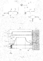
- Fig. 3 shows a complete drive sequence, which comprises a common drive sequence 62 as well as an additional testing sequence 64 according to the method of the invention. Several signals or actions are shown in a single diagram under using the same timeline.
- the uppermost curve which is marked with "POB” shows the action of the power off brake 12, which is a pressure off brake, wherein its action is illustrated through the values "0" and "1".
- the value “0” stands for an activated brake 12 with no hydraulic pressure applied to it, while “1” stands for a deactivated brake 12 with a certain hydraulic pressure applied to it. In the deactivated state, the power off brake 12 should allow a movement of the power control unit 4.
- the curve below which is marked with "ESV" shows a state of an enable solenoid valve, which may illustrated through the values "0" and “1", wherein “0” stands for a closed valve, leading to a lack of pressure at the at least one hydraulic motor 8 and wherein “1” stands for application of the full hydraulic pressure at the at least one hydraulic motor 8, which may then initiate a rotation in case the swash plate is in an appropriate positon.
- n command resembles a commanded speed of the at least one hydraulic motor 8, which is a continuous signal.
- the commanded speed is 0, which stands for a nonrotating hydraulic motor 8. It can be recognized that the sequence of commanded speed leads to a motion of the high lift surfaces 30, e.g. into a retraction direction.
- the lowermost curve which is marked with "AlphaIniS” provides the information whether the swash plate is at the commanded position to allow motor startup. The motor is then capable to withstand external loads when the power off brake 12 is released. If AlphaIniS is "1” it means that the commanded position is reached, which is required for the actual flight state. If AlphaIniS is "0" it means that the commanded position is not reached.
- the common sequence 62 which may be initiated directly after landing, when the high lift surfaces 30 are still extended.
- the solenoid valve integrated in the hydraulic valve block 52 is opened.
- the power off brake 12 is deactivated, i.e. a pressure is applied to the power off brake 12.
- third time delay 68 which considers the delay of the power off brake 12, a speed command is initiated, leading to moving the high lift surfaces 30 from an extended position into a neutral position.
- a target position 70 has been reached, which equals the neutral position.
- the testing sequence 64 starts.
- the power off brake 12 is activated again, i.e. through decoupling from the hydraulic network 56.
- the PCU 4 may not be able to move any more in case it does not experience an undesired condition with limited functionality.
- the solenoid valve remains open.
- a rotation of the at least one hydraulic motor 12 is commanded through commanding a speed of the respective motor by means of the SFCC 46 and 48, respectively.
- the commanded speed may include a direction of rotation, which would lead to an extension of the high lift surfaces 30.
- the absolute value of the commanded speed is indicated in the diagram of Fig. 3 .
- a rotation of the PCU 4 may only be measured in case the power off brake 12 slips. If it does not slip, a dormant undesired condition of the power off brake may be excluded.
- a rotation of the PCU 4 may be detected through the motion sensor in form of the feedback position pickoff unit 40 shown in Fig. 1 . In case the detected motion of exceeds a certain threshold, e.g. a rotation of the PCU 4 of 2° or more, a brake indication signal is to be generated.
- the commandment of the rotational speed to the hydraulic motor 8 may be conducted for a couple of seconds, e.g. 3, 4 or 5 seconds, which allows to reliably identify any dormant undesired condition of the power off brake 12.
- the pressure between the solenoid valve and the hydraulic motor 8 may be detected, wherein the SFCC 46 and 48, respectively, commands a closed solenoid valve.
- a valve indication signal is to be generated.
- the high lift system 2 and the method for testing a component in the high lift system 2 allows to detect hidden undesired conditions of components in the high lift system 2, which may contribute to situations, in which the high lift system 2 experiences a limited operability.
- the safety level of the aircraft is increased without impacting the aircraft weight due to additional components or changed sizing cases.
- the availability of the overall system in flight is unchanged as this invention is active only after landing. All of the above mentioned features are implementable into the aircraft only through software changes.
Description
- The invention relates to a method for testing a component in a high lift system of an aircraft, a high lift system of an aircraft as well as an aircraft having a wing, a hydraulic network and at least one such high lift system.
- Typically, high lift systems of commercial and military aircraft are powered by a centralized drive, also known as power control unit (PCU), which is mounted in a central region of the fuselage and is controllable through a computerized control. The PCU is coupled with a torque shaft system, also known as transmission shaft, which transfers mechanical power to geared actuators at flap or slat panel drive stations distributed along the trailing edge or leading edge of a wing, depending on the desired type of high lift surfaces. A wing tip brake, which is coupled with the transmission shaft and particularly placed in an outer region of the transmission shaft and/or in a tip region of the respective wing is capable of arresting and holding the transmission shaft in certain conditions. The control of the PCU is usually conducted by control computers, such as slat flap control computers (SFCC), which are commonly realized as a redundant arrangement of two independent SFCC that are not only able to control but also to monitor the operation of the high lift system.
- A PCU commonly comprises two independent motors, which are coupled with an output shaft by means of a speed summing differential gear. Each of the motors is provided with a power off brake (POB) for arresting the motor in a commanded position. While at least one of the two motors is commonly a hydraulic motor, the second motor may be realized as a further hydraulic motor, but also as an electric motor, leading to a hybrid PCU. The hydraulic motor may preferably be realized by an axial piston motor comprising a movable swash plate, wherein the orientation of the swash plate inter alia determines the resulting speed of the motor. A solenoid valve may be arranged between a hydraulic network of the aircraft and the respective hydraulic motor, leading to a pressurization of the hydraulic motor and allows the motor to spin when the swash plate is in a desired position.
- Still further, high lift systems usually comprise torque limiters that are adapted for limiting the torque to be introduced into the transmission system. The torque limiters may be mechanical or electronic torque limiters, wherein the latter rely on constantly monitoring an introduced torque, take authority over the motors of the PCU and initiate a reversal once the torque exceeds a predetermined threshold.
-
EP 1 685 026 B1 discloses a device for limiting a load in an aircraft high lift system, said system comprising individual segments of landing flap systems and slat flap systems, and a drive unit, wherein signals from at least two position sensors are measured, a reference variable is calculated form the measured signals and compared with a corresponding threshold value pre-determined from a maximum authorized load, and a control signal is generated for limiting the drive power, when at least one of the reference variables reaches or exceeds the threshold value. -
EP 2 727 831 A1 discloses a method for transferring hydraulic power between at least two hydraulic systems in an aircraft comprising the steps of connecting two hydraulic displacement machines to a differential gear unit having a common mechanical output, arresting the common mechanical output, operating the first hydraulic displacement machine in a motor mode under consumption of hydraulic power of the first hydraulic system such that the second hydraulic displacement machine is mechanically rotated in a pump mode and supplies hydraulic power to the second hydraulic system. -
DE 10 2011 101 348 A1 shows a control device having a rotational drive and a linear control movement, wherein the device has load transmitting components for transferring a force or a torque, a part of which is redundant. A monitoring unit with an actively actuated brake unit is provided for error detection, particularly for detecting functional disorders. -
DE 10 2007 063 157 A1 shows a method for actuating at least one positioning flap on each wing of an aircraft, which positioning flap is actuated by at least two flap coupling devices each including a flap actuator device, where at least on one flap actuator device for each positioning flap a brake mechanism is arranged by means of whose actuation an adjustment state of the respective flap actuator device is lockable. The method comprises the steps of actuating each brake mechanism of a positioning flap individually, subsequently actuating the flap actuator device by means of the drive motor, in the case of a change in the adjustment state of the positioning flap by a predetermined extent and terminating actuation of the positioning flap concerned. - Means for efficiently limiting a torque introduced by a PCU is state of the art. Also, the addition for new functions for components of a PCU without implementing additional components is known. It may be a still further advantage if a PCU driven high lift system has a still further increased safety and reliability without requiring additional components and while maintaining the above torque limiting function.
- It may therefore be an object to propose a high lift system, which comprises a still further increased safety and reliability, preferably accompanied by a minimum or even no additional weight.
- This object is met by a method for testing a component in a high lift system of an ai rcraft having the features of independent claim 1. Advantageous embodiments and further improvements may be gathered from the sub-clai ms and the following description.
- A method for testing a component in a high lift system is proposed, the high lift system comprising a central power control unit for moving high lift surfaces arranged at a wing through providing rotational power by means of a transmission shaft to a plurality of drive stations coupled with the high lift surfaces, which power control unit comprises at least one hydraulic motor coupled with a selectively activatable brake, wherein the at least one hydraulic motor (8) can be coupled to and decoupled from a hydraulic network (56) through a solenoid valve; the method having the steps of activati ng the brake, commanding a rotation of the at least one hydraulic motor for a predetermined period of time, wherein the brake remai ns activated, acquiring a sensor output of a motion sensor coupled with the central power control unit during the commanded rotation of the at least one hydraulic motor, determi ni ng a motion of the power control unit from the acquired sensor output, comparing the determined motion with a predetermined threshold value and generating a brake indication signal in case the determined motion exceeds the predetermined motion threshold value. The method further comprises the previous or subsequent steps of closing the solenoid valve, detecting a hydraulic pressure between a solenoid valve and the at least one hydraulic motor and generating a valve indication signal in case the detected pressure is above a predetermined pressure threshold value.
- In general, the method according to the invention constitutes a testing sequence, which allows to determine any potential dormant undesired conditions that may occur in the high lift system with the above-mentioned setup. This testi ng sequence is explained in the following.
- The high lift system comprises a set of commonly used components. The brake mentioned above is to be considered a power off brake coupled with the at least one hydraulic motor. The term 'selectively activatable_includes all possible methods, processes, designs and setups that allow for activation and release of such a power off brake. However, it is common to use a pressure off brake, which is activated unless a certain hydraulic pressure is present at a fluid port of the brake. This means, that the respective brake is couplable with a manifold, a hydraulic line, a valve or another hydraulic component in order to arrest the respective hydraulic motor when the hydraulic pressure drops below a certain limit.
- During the testi ng sequence, the brake is activated. This means, that the respective hydraulic motor, which is to be tested, should not be able to induce any rotary motion into the high lift system. The brake is activated through releasing the hydraulic pressure.
- Afterwards, a rotation of the at least one hydraulic motor is commanded for a predetermined period of time, wherein the brake remains activated. As explained above, the at least one hydraulic motor should not be able to provide any rotation as the brake remains activated. Concurrently, through a motion sensor at the PCU, e.g. at a common output shaft, the motion of the PCU is monitored. In case all components work as desired, the sensor output should approximately be zero and may merely indicate any gear play or inaccuracies of the respective sensor.
- Through consideration of a certain geometrical or physical factor it is possible to determi ne a motion of the power control unit or a value that represents the motion from the acqui red sensor output. The determined motion may be compared with a predetermined threshold value, which should be chosen such that the above-mentioned effects may be compensated. However, it is clear that if a prominent motion of the power control unit from the acquired sensor output is determined, a brake indication signal is generated. This signal is dedicated for indicating that the brake at a respective hydraulic motor is experiencing an abnormal condition. By receiving a brake indication signal in a control unit of the aircraft, through an indication in the cockpit or any other process that can be brought into dependency on the brake indication signal, maintenance actions can be initiated.
- The additional aspect of detecting the hydraulic pressure between the solenoid valve and the at least one hydraulic motor leads to the ability of identifying another dormant undesired condition, as a solenoid valve must be able to reliably couple or decouple the at least one hydraulic motor from a hydraulic network. In case the solenoid valve is closed, such that the at least one hydraulic motor should not experience a hydraulic pressure, it is generated a valve indication signal in case the pressure remains above a predetermined threshold value. This may happen when the solenoid valve is defect. Should the pressure be too high, resulti ng in a motor torque above the design limit, the crew will be informed of the presence of a failure preventing the dispatch of the aircraft. Hence, by generating the valve indication signal and through initiating appropriate actions in a control unit of the aircraft, in the cockpit or the like, maintenance actions can be initiated.
- A Itogether, the method accordi ng to the i nventi on provides an excel lent ability for recognizing any dormant undesired conditions in components of the high lift system of the ai rcraft, without having to add any further components, sensors, wirings, mechanical means, etc., while the safety and reliability are clearly increased.
- In an advantageous embodiment, a previous step may be included into the above method, which comprises moving the high lift system surfaces to a neutral position by rotating the power control unit before activating the brake. Hence, the testing sequence according to the invention may simply be conducted subsequently after moving the high lift surfaces back into the neutral positi on right after the ai rcraft has landed. This may even be conducted during taxiing of the aircraft, while it may also be possible to conduct this method on ground after reachi ng a parking position.
- Still further, moving the high lift surfaces to the neutral position comprises rotating the at least one hydraulic motor in a first direction of rotation and commanding the rotati on of the at least one hydraulic motor comprises rotating the at least one hydraulic motor in a second direction of rotation. In case the high lift surfaces are moved into a neutral position leading to a clean wing configuration, it is feasible to command the at least one hydraulic motor for rotati on into an extension direction. Hence, mechani cal stresses introduced into the high lift system during the testi ng sequence due to end stops or the such are clearly reduced.
- In another advantageous embodiment, between moving the high lift surfaces to the neutral position and commanding the rotation of the at least one hydraulic motor, a solenoid valve between a hydraulic network and the at least one hydraulic motor remains activated. Hence, the test sequence may be conducted directly after moving the high lift surfaces to the neutral position. The testi ng sequence may be a standard addition to a common retraction sequence and, at the same time, even allows to eliminate two additional actuations of the respective solenoid valve.
It may be feasible and advantageous to send a speed command to a speed control unit coupled with the at least one hydraulic motor for commanding a rotation of the at least one hydraulic motor. For example, a digitally controlled over-center variable displacement motor may be utilized, wherein the motor control is established by a closed loop layout to maintain speed and torque command inputs. The control algorithms are implemented in the speed control unit, which is provided with all required data to control the hydraulic motor. Hence, commonly used signal paths may be used for conducting the operation of the hydraulic motor during the testing sequence without having to include a separate control logic for the at least one hydraulic motor. The implementation of a core of the method accordi ng to the invention may therefore be conducted through modification of a software in the control unit, e.g. the SFCC.
As mentioned above, the brake may be a pressure off brake, wherein activating the brake comprises decoupling the brake from a hydraulic network. Hence, a commonly used brake may remain in the high lift system. In the testing sequence a control of the pressure off brake may just be conducted through overriding the usual activation after retraction of the high lift surfaces.
Commanding the rotati on of the at least one hydraulic motor for a predetermined period of ti me may be conducted with a first ti me delay after the brake is activated. A ny reaction ti mes of the brake and of all components between a control unit and the brake can be neglected. However, the first time delay may be extremely short in the range of a low number of seconds. - The invention further relates to a high lift system of an aircraft according to claim 9, comprising a plurality of high lift surfaces movably arrangeable at a wing, a plurality of drive stations coupled with the high lift surfaces, a transmission shaft coupled with the plurality of drive stations, a central power control unit coupled with the transmission shaft for moving the high lift surfaces through driving the drive stations, the power control unit comprising at least one hydraulic motor coupled with a brake and a control unit.
- As explained above, the control unit is adapted for conducting the method explained above. In particular, the control unit is adapted for conducti ng a test sequence comprising of activating the brake, commanding a rotation of the at least one hydraulic motor for a predetermined period of time, wherein the brake remai ns activated, acquiring a sensor output of a motion sensor coupled with the central power control unit during the commanded rotation of the at least one hydraulic motor, determining a motion of the power control unit from the acquired sensor output, comparing the determined motion with a predetermined threshold value, and generating a brake indication signal in case the determined motion exceeds the predetermined motion threshold value.
Again, the brake may be a pressure off brake and activating the brake may comprise decoupling the brake from a hydraulic network. - The control unit is further adapted for determining a hydraulic pressure between a solenoid valve and the at least one hydraulic motor and generati ng a valve indication signal in case the detected pressure is above a predetermined pressure threshold value.
- Still further, the high lift surfaces may be trailing edge flaps or leading edge slats. Commonly, both types of high lift surfaces may be driven by a separate power control unit, such that two of these high lift systems may be integrated into one aircraft and all high lift systems may be able to conduct the method according to the above.
- Preferably, the control unit may be integrated into a control computer for controlling the high lift surfaces. Consequently, no additional components are used and the control computer may simply be modified on a software side. Hence, no additional weight arises and the high lift system experiences a clearly increased safety and reliability. Such a control computer may particularly include a slat flap control computer.
- The application of the above mentioned features may particularly accompany a high lift system that uses electronic torque limiters.
- Still further, the invention relates to an aircraft having a wing, a hydraulic network and at least one of the above-mentioned high lift systems.
- In this regard it is indicated that the method according to the above may be conducted for each hydraulic motor in each high lift system integrated into the aircraft, either by a grouped, subsequent or synchronous way.
- Further characteristics, advantages and application options of the present invention are disclosed in the following description of the exemplary embodiments in the figures. All the described and/or illustrated characteristics per se and in any combination form the subject of the invention, even irrespective of their composition in the individual claims or their interrelationships. Furthermore, identical or similar components in the figures have the same reference characters.
-
Fig. 1 shows a high lift system in a schematic, block-oriented view. -
Fig. 2 shows a schematic view of a power control unit. -
Fig. 3 shows a drive sequence in a diagrammatic view. - In
Fig. 1 , a general setup of ahigh lift system 2 is shown in the example of a leading edge slat system. Here, apower control unit 4 comprises anelectric motor 6, ahydraulic motor 8 with a variable displacement, a first power offbrake 10 coupled with theelectric motor 6 as well as a second power offbrake 12 coupled with thehydraulic motor 8. Bothmotors input shaft 14, 16 of a speed summing differential 18, which in turn comprises twooutput shafts transmission shaft system transmission shafts several drive stations 28 distributed along the respective wing half, wherein each of a plurality of movably supported high lift surfaces 30 is driven by twoindividual drive stations 28. - Each of the
transmission shafts wing tip brake shafts respective shafts transmission shaft unit respective shaft transmission shafts drive stations 28 of both wing halves. - The differential 18 may further comprise a feedback position pickoff unit 40 that allows to monitor the rotation of the
output shafts Torque sensor units output shafts output shafts - All of the asymmetry
position pickoff units torque sensor units control units SFCC 48. The torque in thetransmission shafts torque sensor units transmission shafts system 2 may be arrested through engaging thebrake corresponding motor - The
electric motor 6 may be a brushless motor controlled through adigital drive control 50, coupled with the SFCCs 46 and 48. Thehydraulic motor 8 is controlled through ahydraulic valve block 52, which is coupled with a manifold 54 connected to theSFCCs hydraulic network 56 and contains all required components, such as an enabling solenoid valve and a pressure off brake solenoid valve to pressurize thehydraulic motor 8 and to control the pressure offbrake 12. In a default high lift operating mode thewing tip brakes PCU 4 is providing sufficient mechanical power to operate thehigh lift system 2 with a commanded speed into any gated position. -
Fig. 2 depicts thePCU 4 in another, schematic view. Here, theelectric motor 6 and thehydraulic motor 8 are coupled with the differential 18 through power offbrakes hydraulic motor 8 is controlled by commanding a motor swash plate into a required position, while the hydraulic power is provided by the associatedhydraulic network 56. The motor flow demand is, as part of a closed loop control algorithm, limited with the objective not to overload the hydraulic network. This may require information regarding the hydraulic pressure provided by a pressure transducer as part of a hydraulic drive channel and pressure data provided by the hydraulic network to theSFCC hydraulic motor 8 may thereby be coupled with acontroller interface 58. Theelectric motor 6, which is supplied with electric power through anelectric network 60, is controllable by means of closed loop speed control accordingly. -
Fig. 3 shows a complete drive sequence, which comprises acommon drive sequence 62 as well as anadditional testing sequence 64 according to the method of the invention. Several signals or actions are shown in a single diagram under using the same timeline. - The uppermost curve, which is marked with "POB" shows the action of the power off
brake 12, which is a pressure off brake, wherein its action is illustrated through the values "0" and "1". The value "0" stands for an activatedbrake 12 with no hydraulic pressure applied to it, while "1" stands for a deactivatedbrake 12 with a certain hydraulic pressure applied to it. In the deactivated state, the power offbrake 12 should allow a movement of thepower control unit 4. - The curve below, which is marked with "ESV", shows a state of an enable solenoid valve, which may illustrated through the values "0" and "1", wherein "0" stands for a closed valve, leading to a lack of pressure at the at least one
hydraulic motor 8 and wherein "1" stands for application of the full hydraulic pressure at the at least onehydraulic motor 8, which may then initiate a rotation in case the swash plate is in an appropriate positon. - The curve below, which is marked with "ncommand" resembles a commanded speed of the at least one
hydraulic motor 8, which is a continuous signal. At the beginning and at the end of each sequence, the commanded speed is 0, which stands for a nonrotatinghydraulic motor 8. It can be recognized that the sequence of commanded speed leads to a motion of the high lift surfaces 30, e.g. into a retraction direction. - The lowermost curve, which is marked with "AlphaIniS" provides the information whether the swash plate is at the commanded position to allow motor startup. The motor is then capable to withstand external loads when the power off
brake 12 is released. If AlphaIniS is "1" it means that the commanded position is reached, which is required for the actual flight state. If AlphaIniS is "0" it means that the commanded position is not reached. - During the
common sequence 62, which may be initiated directly after landing, when the high lift surfaces 30 are still extended. Hence, the solenoid valve integrated in thehydraulic valve block 52, is opened. After asecond time delay 66, the power offbrake 12 is deactivated, i.e. a pressure is applied to the power offbrake 12. After a further,third time delay 68, which considers the delay of the power offbrake 12, a speed command is initiated, leading to moving the high lift surfaces 30 from an extended position into a neutral position. At a certain time, atarget position 70 has been reached, which equals the neutral position. Here, thetesting sequence 64 starts. - After reaching the
target position 70, the power offbrake 12 is activated again, i.e. through decoupling from thehydraulic network 56. Hence, thePCU 4 may not be able to move any more in case it does not experience an undesired condition with limited functionality. However, the solenoid valve remains open. After afirst time delay 72, which has been explained in the summary of the invention, a rotation of the at least onehydraulic motor 12 is commanded through commanding a speed of the respective motor by means of theSFCC Fig. 3 . - However, a rotation of the
PCU 4 may only be measured in case the power offbrake 12 slips. If it does not slip, a dormant undesired condition of the power off brake may be excluded. Vice versa, in case the power offbrake 12 slip, a rotation of thePCU 4 may be detected through the motion sensor in form of the feedback position pickoff unit 40 shown inFig. 1 . In case the detected motion of exceeds a certain threshold, e.g. a rotation of thePCU 4 of 2° or more, a brake indication signal is to be generated. - The commandment of the rotational speed to the
hydraulic motor 8 may be conducted for a couple of seconds, e.g. 3, 4 or 5 seconds, which allows to reliably identify any dormant undesired condition of the power offbrake 12. - Right thereafter or before this, the pressure between the solenoid valve and the
hydraulic motor 8 may be detected, wherein theSFCC - Altogether, the
high lift system 2 and the method for testing a component in thehigh lift system 2 allows to detect hidden undesired conditions of components in thehigh lift system 2, which may contribute to situations, in which thehigh lift system 2 experiences a limited operability. Hence, the safety level of the aircraft is increased without impacting the aircraft weight due to additional components or changed sizing cases. In addition to this safety level increase, the availability of the overall system in flight is unchanged as this invention is active only after landing. All of the above mentioned features are implementable into the aircraft only through software changes. - In addition, it should be pointed out that "comprising" does not exclude other elements or steps, and "a" or "an" does not exclude a plural number. Furthermore, it should be pointed out that characteristics or steps which have been described with reference to one of the above exemplary embodiments can also be used in combination with other characteristics or steps of other exemplary embodiments described above. Reference characters in the claims are not to be interpreted as limitations.
Claims (13)
- Method for testing a component in a high lift system (2) of an aircraft, the high lift system (2) comprising a central power control unit (4) for moving high lift surfaces (30) arranged at a wing through providing rotational power by means of a transmission shaft (24, 26) to a plurality of drive stations (28) coupled with the high lift surfaces (30); which power control unit (4) comprises at least one hydraulic motor (8) coupled with a selectively activatable brake (12), wherein the at least one hydraulic motor (8) can be coupled to and decoupled from a hydraulic network (56) by opening and closing a solenoid valve; the method comprising the steps of:- opening the solenoid valve;wherein the method further comprises the previous or subsequent steps of closing the solenoid valve, detecting a hydraulic pressure between the solenoid valve and the at least one hydraulic motor (8) and generating a valve indication signal in case the detected pressure is above a predetermined pressure threshold value.- activating the brake (12),- commanding a rotation of the at least one hydraulic motor (8) for a predetermined period of time, wherein the brake (12) remains activated,- acquiring a sensor output of a motion sensor (40) coupled with the central power control unit (4) during the commanded rotation of the at least one hydraulic motor (8),- determining a motion of the power control unit (4) from the acquired sensor output,- comparing the determined motion with a predetermined threshold value, and- generating a brake indication signal in case the determined motion exceeds the predetermined motion threshold value,
- Method of claim 1, further comprising a step of moving the high lift surfaces (30) to a neutral position by rotating the power control unit (4) between opening the solenoid valve and activating the at least one brake (12).
- Method of claim 2, wherein moving the high lift surfaces (30) to the neutral position comprises rotating the at least one hydraulic motor (8) in a first direction of rotation and wherein commanding the rotation of the at least one hydraulic motor (8) comprises rotating the at least one hydraulic motor (8) in a second direction of rotation.
- Method of claim 2 or 3, wherein between moving the high lift surfaces (30) to the neutral position and commanding the rotation of the at least one hydraulic motor (8) the solenoid valve between the hydraulic network (56) and the at least one hydraulic motor (8) remains open.
- Method of any of claims 2 to 4 wherein the method is conducted after landing of the aircraft.
- Method of any of the previous claims, wherein commanding a rotation of the at least one hydraulic motor (8) comprises sending a speed command to a speed control unit coupled with the at least one hydraulic motor (8).
- Method of any of the previous claims, wherein the brake (12) is a pressure off brake and wherein activating the brake (12) comprises decoupling the brake (12) from a hydraulic network (56).
- Method of any of the previous claims, wherein commanding the rotation of the at least one hydraulic motor (8) for a predetermined period of time is conducted with a first time delay (72) after the brake (12) is activated.
- High lift system (2) for an aircraft, comprising:- a plurality of high lift surfaces (30) movably arrangeable at a wing,- a plurality of drive stations (28) coupled with the high lift surfaces (30),- a transmission shaft (24, 26) coupled with the plurality of drive stations (28),- a central power control unit (4) coupled with the transmission shaft (24, 26) for moving the high lift surfaces (30) through driving the drive stations (28), the power control unit (4) comprising at least one hydraulic motor (8) coupled with a selectively activatable brake (12) and a solenoid valve enabling to couple and decouple the at least one hydraulic motor (8) from a hydraulic network (56), and- a control unit (46, 48),wherein the control unit (46, 48) is adapted for carrying out the method of claim 1.
- High lift system (2) of claim 10, wherein the brake (12) is a pressure off brake and activating the brake (12) comprises decoupling the brake (12) from a hydraulic network (56).
- High lift system (2) of claim 9 or 10, wherein the high lift surfaces (30) are trailing edge flaps or leading edge slats.
- High lift system (2) of any of the claims 9 to 11, wherein the control unit (46, 48) is integrated into a control computer for controlling the high lift surfaces (30).
- Aircraft, having a wing, a hydraulic network (56) and at least one high lift system (2) of any of the claims 9 to 12.
Priority Applications (5)
| Application Number | Priority Date | Filing Date | Title |
|---|---|---|---|
| EP14199892.2A EP3037346B1 (en) | 2014-12-22 | 2014-12-22 | Method for testing a component in a high lift system of an aircraft |
| CA2915273A CA2915273C (en) | 2014-12-22 | 2015-12-14 | Method for testing a component in a high lift system of an aircraft |
| JP2015248532A JP2016117481A (en) | 2014-12-22 | 2015-12-21 | Method for testing component in high lift system of aircraft |
| US14/978,612 US9630725B2 (en) | 2014-12-22 | 2015-12-22 | Method for testing a component in a high lift system of an aircraft |
| CN201510969280.1A CN105711855B (en) | 2014-12-22 | 2015-12-22 | Method for the part in the high-lift system of testing flying vehicle |
Applications Claiming Priority (1)
| Application Number | Priority Date | Filing Date | Title |
|---|---|---|---|
| EP14199892.2A EP3037346B1 (en) | 2014-12-22 | 2014-12-22 | Method for testing a component in a high lift system of an aircraft |
Publications (2)
| Publication Number | Publication Date |
|---|---|
| EP3037346A1 EP3037346A1 (en) | 2016-06-29 |
| EP3037346B1 true EP3037346B1 (en) | 2018-10-24 |
Family
ID=52103227
Family Applications (1)
| Application Number | Title | Priority Date | Filing Date |
|---|---|---|---|
| EP14199892.2A Active EP3037346B1 (en) | 2014-12-22 | 2014-12-22 | Method for testing a component in a high lift system of an aircraft |
Country Status (5)
| Country | Link |
|---|---|
| US (1) | US9630725B2 (en) |
| EP (1) | EP3037346B1 (en) |
| JP (1) | JP2016117481A (en) |
| CN (1) | CN105711855B (en) |
| CA (1) | CA2915273C (en) |
Families Citing this family (18)
| Publication number | Priority date | Publication date | Assignee | Title |
|---|---|---|---|---|
| EP3037347B1 (en) * | 2014-12-22 | 2019-02-06 | Airbus Operations GmbH | Method for determining a state of a component in a high lift system of an aircraft |
| EP3037346B1 (en) * | 2014-12-22 | 2018-10-24 | Airbus Operations GmbH | Method for testing a component in a high lift system of an aircraft |
| FR3047725B1 (en) * | 2016-02-12 | 2018-01-26 | Airbus Operations | AIRCRAFT HYPERSUSTENT DEVICE EQUIPPED WITH AT LEAST ONE DIFFERENTIATED COUPLING SYSTEM |
| CN105923169B (en) * | 2016-07-06 | 2018-05-11 | 西安交通大学 | A kind of oil electricity mixing unmanned vehicle electric power system test platform and its test method |
| CN106347635B (en) * | 2016-11-01 | 2018-01-02 | 中国商用飞机有限责任公司北京民用飞机技术研究中心 | A kind of plane lease loads loading device |
| CN106828971B (en) * | 2016-12-13 | 2019-04-02 | 南昌航空大学 | A kind of experimental provision measuring single duct and single duct aircraft lift |
| CN106586029B (en) * | 2016-12-28 | 2019-06-11 | 中国航空工业集团公司西安飞机设计研究所 | A kind of test macro of promotion Force control system |
| US10336437B2 (en) * | 2017-05-05 | 2019-07-02 | Hamilton Sundstrand Corporation | Method to measure aircraft high-lift system brake response time |
| EP3474103B1 (en) | 2017-10-20 | 2022-03-09 | Goodrich Actuation Systems Limited | Monitoring system for identifying an operating state of a motor |
| US10766601B2 (en) * | 2017-11-28 | 2020-09-08 | The Boeing Company | Aircraft wing flaps having aerodynamic restoration doors |
| DE102018121856A1 (en) * | 2018-09-07 | 2020-03-12 | Liebherr-Aerospace Lindenberg Gmbh | High lift system for an aircraft |
| GB201901112D0 (en) * | 2019-01-28 | 2019-03-13 | Rolls Royce Plc | Shaft monitoring system |
| CN109733642B (en) * | 2019-01-31 | 2022-04-05 | 西北工业大学 | Model calibration system and method based on wingtip brake device of high lift control system |
| CN113044236A (en) * | 2019-12-26 | 2021-06-29 | 中国航空工业集团公司西安飞机设计研究所 | Test system and test method for airplane high lift control system |
| US11794877B2 (en) | 2020-12-21 | 2023-10-24 | Hamilton Sundstrand Corporation | Integrated assymmetry brake mechanism |
| EP4112452A1 (en) * | 2021-06-29 | 2023-01-04 | Airbus Operations GmbH | Method and apparatus for conducting health monitoring |
| EP4112453A1 (en) * | 2021-06-29 | 2023-01-04 | Airbus Operations GmbH | Method and apparatus for conducting health monitoring during ground operation |
| CN115042983B (en) * | 2022-08-11 | 2022-11-11 | 北京天创凯睿科技有限公司 | Measurement protection mechanism for airplane automatic accelerator, measurement mechanism and use method |
Family Cites Families (19)
| Publication number | Priority date | Publication date | Assignee | Title |
|---|---|---|---|---|
| DE19724117A1 (en) * | 1997-06-09 | 1998-12-10 | Zf Luftfahrttechnik Gmbh | Brake for a lift flap adjustment mechanism |
| GB9823599D0 (en) * | 1998-10-28 | 1998-12-23 | Lucas Ind Plc | Brake assembly |
| US6824099B1 (en) * | 2003-07-10 | 2004-11-30 | The Boeing Company | Brake systems for aircraft wing flaps and other control surfaces |
| DE10353672A1 (en) | 2003-11-12 | 2005-06-23 | Airbus Deutschland Gmbh | Method for load limitation in drive systems |
| DE102007023394A1 (en) * | 2007-05-18 | 2008-11-20 | Airbus Deutschland Gmbh | Method and device for fault detection in the load path of a spindle actuator |
| DE102007063157A1 (en) * | 2007-12-30 | 2009-07-09 | Airbus Deutschland Gmbh | System for actuating at least one valve of an aircraft and a method for checking the system |
| US8504221B2 (en) * | 2009-01-16 | 2013-08-06 | The Boeing Company | Apparatus and method for controlling a control surface of a vehicle based on a load identified on the control surface |
| DE102009053126A1 (en) * | 2009-11-13 | 2011-05-19 | Airbus Operations Gmbh | Control system of an aircraft with a valve |
| DE102010024711A1 (en) * | 2010-06-23 | 2011-12-29 | Airbus Operations Gmbh | Apparatus and method for detecting mechanical loads on pushers |
| DE102010047512A1 (en) * | 2010-10-05 | 2012-04-05 | Airbus Operations Gmbh | High-lift system for an aircraft with two separate drive units |
| DE102011101348A1 (en) * | 2011-05-12 | 2012-11-15 | Liebherr-Aerospace Lindenberg Gmbh | Control device, particularly for aircraft, has rotational drive and linear control movement, which has load transmitting components for transferring force or torque, where part of load transmitting components is redundant |
| US9327600B1 (en) * | 2011-09-06 | 2016-05-03 | Neeme Systems Solutions, Inc. | Aircraft utilities and power distribution system |
| US9499252B2 (en) * | 2011-10-01 | 2016-11-22 | The Boeing Company | Wing fold controller |
| EP2690007B1 (en) * | 2012-07-26 | 2016-08-31 | Airbus Operations GmbH | Method for generating hydraulic power in an aircraft, use of a hybrid power control unit and drive system |
| EP2727831A1 (en) | 2012-10-30 | 2014-05-07 | Airbus Operations GmbH | Method for transferring hydraulic power between two hydraulic systems in an aircraft, use of a power control unit and drive system in an aircraft |
| GB2513133B (en) * | 2013-04-16 | 2015-07-08 | Ge Aviat Systems Ltd | Methods for predicting a speed brake system fault |
| EP2808576B1 (en) * | 2013-05-31 | 2019-03-20 | Airbus Operations GmbH | Joint arrangement, drive system for driving control surfaces of an aircraft and aircraft with such a drive system |
| EP2955104B1 (en) * | 2014-06-11 | 2017-08-09 | Airbus Operations GmbH | System and method for moving a high lift surface relative to the wing of an aircraft |
| EP3037346B1 (en) * | 2014-12-22 | 2018-10-24 | Airbus Operations GmbH | Method for testing a component in a high lift system of an aircraft |
-
2014
- 2014-12-22 EP EP14199892.2A patent/EP3037346B1/en active Active
-
2015
- 2015-12-14 CA CA2915273A patent/CA2915273C/en active Active
- 2015-12-21 JP JP2015248532A patent/JP2016117481A/en active Pending
- 2015-12-22 US US14/978,612 patent/US9630725B2/en active Active
- 2015-12-22 CN CN201510969280.1A patent/CN105711855B/en active Active
Non-Patent Citations (1)
| Title |
|---|
| None * |
Also Published As
| Publication number | Publication date |
|---|---|
| CN105711855A (en) | 2016-06-29 |
| US9630725B2 (en) | 2017-04-25 |
| CN105711855B (en) | 2018-01-12 |
| CA2915273A1 (en) | 2016-06-22 |
| CA2915273C (en) | 2023-06-27 |
| US20160176540A1 (en) | 2016-06-23 |
| EP3037346A1 (en) | 2016-06-29 |
| JP2016117481A (en) | 2016-06-30 |
Similar Documents
| Publication | Publication Date | Title |
|---|---|---|
| EP3037346B1 (en) | Method for testing a component in a high lift system of an aircraft | |
| US8746614B2 (en) | System for actuating at least one positioning flap of an aircraft and a method for monitoring the system | |
| EP3398851B1 (en) | Method to measure aircraft high-lift system brake response time | |
| US8888036B2 (en) | Primary flight controls | |
| EP2955104B1 (en) | System and method for moving a high lift surface relative to the wing of an aircraft | |
| EP2625104B1 (en) | High lift system for an aircraft with a separate drive unit for each wing half | |
| US8868261B2 (en) | Monitoring device for an actuation system of an aircraft, actuation system and method for reconfiguring the actuation system | |
| US20110062282A1 (en) | Fault-tolerant actuating system for adjusting flaps of an aircraft, comprising adjustment kinematics with a fixed pivot, and a method for monitoring an actuating system | |
| US9715770B2 (en) | Systems and methods for built in test equipment for a brake control system | |
| US20100203819A1 (en) | Variable set point all-electric pressure relief valve and control, independent from the automatic cabin pressure control system | |
| CN111619791A (en) | Landing gear system operation | |
| EP3613666B1 (en) | Actuator system | |
| EP3909818B1 (en) | Detection of brake failure using wheel speed during landing gear retraction | |
| EP4112452A1 (en) | Method and apparatus for conducting health monitoring | |
| EP4112453A1 (en) | Method and apparatus for conducting health monitoring during ground operation | |
| CN113386949A (en) | Control system for controlling flaps and/or slats of an aircraft, and aircraft |
Legal Events
| Date | Code | Title | Description |
|---|---|---|---|
| PUAI | Public reference made under article 153(3) epc to a published international application that has entered the european phase |
Free format text: ORIGINAL CODE: 0009012 |
|
| AK | Designated contracting states |
Kind code of ref document: A1 Designated state(s): AL AT BE BG CH CY CZ DE DK EE ES FI FR GB GR HR HU IE IS IT LI LT LU LV MC MK MT NL NO PL PT RO RS SE SI SK SM TR |
|
| AX | Request for extension of the european patent |
Extension state: BA ME |
|
| STAA | Information on the status of an ep patent application or granted ep patent |
Free format text: STATUS: REQUEST FOR EXAMINATION WAS MADE |
|
| 17P | Request for examination filed |
Effective date: 20161227 |
|
| RBV | Designated contracting states (corrected) |
Designated state(s): AL AT BE BG CH CY CZ DE DK EE ES FI FR GB GR HR HU IE IS IT LI LT LU LV MC MK MT NL NO PL PT RO RS SE SI SK SM TR |
|
| STAA | Information on the status of an ep patent application or granted ep patent |
Free format text: STATUS: EXAMINATION IS IN PROGRESS |
|
| 17Q | First examination report despatched |
Effective date: 20171110 |
|
| GRAP | Despatch of communication of intention to grant a patent |
Free format text: ORIGINAL CODE: EPIDOSNIGR1 |
|
| STAA | Information on the status of an ep patent application or granted ep patent |
Free format text: STATUS: GRANT OF PATENT IS INTENDED |
|
| INTG | Intention to grant announced |
Effective date: 20180621 |
|
| GRAS | Grant fee paid |
Free format text: ORIGINAL CODE: EPIDOSNIGR3 |
|
| GRAA | (expected) grant |
Free format text: ORIGINAL CODE: 0009210 |
|
| STAA | Information on the status of an ep patent application or granted ep patent |
Free format text: STATUS: THE PATENT HAS BEEN GRANTED |
|
| AK | Designated contracting states |
Kind code of ref document: B1 Designated state(s): AL AT BE BG CH CY CZ DE DK EE ES FI FR GB GR HR HU IE IS IT LI LT LU LV MC MK MT NL NO PL PT RO RS SE SI SK SM TR |
|
| REG | Reference to a national code |
Ref country code: CH Ref legal event code: EP |
|
| REG | Reference to a national code |
Ref country code: IE Ref legal event code: FG4D |
|
| REG | Reference to a national code |
Ref country code: AT Ref legal event code: REF Ref document number: 1056367 Country of ref document: AT Kind code of ref document: T Effective date: 20181115 |
|
| REG | Reference to a national code |
Ref country code: DE Ref legal event code: R096 Ref document number: 602014034564 Country of ref document: DE |
|
| REG | Reference to a national code |
Ref country code: NL Ref legal event code: MP Effective date: 20181024 |
|
| REG | Reference to a national code |
Ref country code: LT Ref legal event code: MG4D |
|
| REG | Reference to a national code |
Ref country code: AT Ref legal event code: MK05 Ref document number: 1056367 Country of ref document: AT Kind code of ref document: T Effective date: 20181024 |
|
| PG25 | Lapsed in a contracting state [announced via postgrant information from national office to epo] |
Ref country code: NL Free format text: LAPSE BECAUSE OF FAILURE TO SUBMIT A TRANSLATION OF THE DESCRIPTION OR TO PAY THE FEE WITHIN THE PRESCRIBED TIME-LIMIT Effective date: 20181024 |
|
| PG25 | Lapsed in a contracting state [announced via postgrant information from national office to epo] |
Ref country code: ES Free format text: LAPSE BECAUSE OF FAILURE TO SUBMIT A TRANSLATION OF THE DESCRIPTION OR TO PAY THE FEE WITHIN THE PRESCRIBED TIME-LIMIT Effective date: 20181024 Ref country code: LV Free format text: LAPSE BECAUSE OF FAILURE TO SUBMIT A TRANSLATION OF THE DESCRIPTION OR TO PAY THE FEE WITHIN THE PRESCRIBED TIME-LIMIT Effective date: 20181024 Ref country code: NO Free format text: LAPSE BECAUSE OF FAILURE TO SUBMIT A TRANSLATION OF THE DESCRIPTION OR TO PAY THE FEE WITHIN THE PRESCRIBED TIME-LIMIT Effective date: 20190124 Ref country code: AT Free format text: LAPSE BECAUSE OF FAILURE TO SUBMIT A TRANSLATION OF THE DESCRIPTION OR TO PAY THE FEE WITHIN THE PRESCRIBED TIME-LIMIT Effective date: 20181024 Ref country code: IS Free format text: LAPSE BECAUSE OF FAILURE TO SUBMIT A TRANSLATION OF THE DESCRIPTION OR TO PAY THE FEE WITHIN THE PRESCRIBED TIME-LIMIT Effective date: 20190224 Ref country code: FI Free format text: LAPSE BECAUSE OF FAILURE TO SUBMIT A TRANSLATION OF THE DESCRIPTION OR TO PAY THE FEE WITHIN THE PRESCRIBED TIME-LIMIT Effective date: 20181024 Ref country code: PL Free format text: LAPSE BECAUSE OF FAILURE TO SUBMIT A TRANSLATION OF THE DESCRIPTION OR TO PAY THE FEE WITHIN THE PRESCRIBED TIME-LIMIT Effective date: 20181024 Ref country code: LT Free format text: LAPSE BECAUSE OF FAILURE TO SUBMIT A TRANSLATION OF THE DESCRIPTION OR TO PAY THE FEE WITHIN THE PRESCRIBED TIME-LIMIT Effective date: 20181024 Ref country code: BG Free format text: LAPSE BECAUSE OF FAILURE TO SUBMIT A TRANSLATION OF THE DESCRIPTION OR TO PAY THE FEE WITHIN THE PRESCRIBED TIME-LIMIT Effective date: 20190124 Ref country code: HR Free format text: LAPSE BECAUSE OF FAILURE TO SUBMIT A TRANSLATION OF THE DESCRIPTION OR TO PAY THE FEE WITHIN THE PRESCRIBED TIME-LIMIT Effective date: 20181024 |
|
| PG25 | Lapsed in a contracting state [announced via postgrant information from national office to epo] |
Ref country code: GR Free format text: LAPSE BECAUSE OF FAILURE TO SUBMIT A TRANSLATION OF THE DESCRIPTION OR TO PAY THE FEE WITHIN THE PRESCRIBED TIME-LIMIT Effective date: 20190125 Ref country code: RS Free format text: LAPSE BECAUSE OF FAILURE TO SUBMIT A TRANSLATION OF THE DESCRIPTION OR TO PAY THE FEE WITHIN THE PRESCRIBED TIME-LIMIT Effective date: 20181024 Ref country code: SE Free format text: LAPSE BECAUSE OF FAILURE TO SUBMIT A TRANSLATION OF THE DESCRIPTION OR TO PAY THE FEE WITHIN THE PRESCRIBED TIME-LIMIT Effective date: 20181024 Ref country code: AL Free format text: LAPSE BECAUSE OF FAILURE TO SUBMIT A TRANSLATION OF THE DESCRIPTION OR TO PAY THE FEE WITHIN THE PRESCRIBED TIME-LIMIT Effective date: 20181024 Ref country code: PT Free format text: LAPSE BECAUSE OF FAILURE TO SUBMIT A TRANSLATION OF THE DESCRIPTION OR TO PAY THE FEE WITHIN THE PRESCRIBED TIME-LIMIT Effective date: 20190224 |
|
| REG | Reference to a national code |
Ref country code: DE Ref legal event code: R097 Ref document number: 602014034564 Country of ref document: DE |
|
| PG25 | Lapsed in a contracting state [announced via postgrant information from national office to epo] |
Ref country code: DK Free format text: LAPSE BECAUSE OF FAILURE TO SUBMIT A TRANSLATION OF THE DESCRIPTION OR TO PAY THE FEE WITHIN THE PRESCRIBED TIME-LIMIT Effective date: 20181024 Ref country code: IT Free format text: LAPSE BECAUSE OF FAILURE TO SUBMIT A TRANSLATION OF THE DESCRIPTION OR TO PAY THE FEE WITHIN THE PRESCRIBED TIME-LIMIT Effective date: 20181024 Ref country code: CZ Free format text: LAPSE BECAUSE OF FAILURE TO SUBMIT A TRANSLATION OF THE DESCRIPTION OR TO PAY THE FEE WITHIN THE PRESCRIBED TIME-LIMIT Effective date: 20181024 |
|
| REG | Reference to a national code |
Ref country code: CH Ref legal event code: PL |
|
| PG25 | Lapsed in a contracting state [announced via postgrant information from national office to epo] |
Ref country code: SK Free format text: LAPSE BECAUSE OF FAILURE TO SUBMIT A TRANSLATION OF THE DESCRIPTION OR TO PAY THE FEE WITHIN THE PRESCRIBED TIME-LIMIT Effective date: 20181024 Ref country code: RO Free format text: LAPSE BECAUSE OF FAILURE TO SUBMIT A TRANSLATION OF THE DESCRIPTION OR TO PAY THE FEE WITHIN THE PRESCRIBED TIME-LIMIT Effective date: 20181024 Ref country code: SM Free format text: LAPSE BECAUSE OF FAILURE TO SUBMIT A TRANSLATION OF THE DESCRIPTION OR TO PAY THE FEE WITHIN THE PRESCRIBED TIME-LIMIT Effective date: 20181024 Ref country code: LU Free format text: LAPSE BECAUSE OF NON-PAYMENT OF DUE FEES Effective date: 20181222 Ref country code: EE Free format text: LAPSE BECAUSE OF FAILURE TO SUBMIT A TRANSLATION OF THE DESCRIPTION OR TO PAY THE FEE WITHIN THE PRESCRIBED TIME-LIMIT Effective date: 20181024 Ref country code: MC Free format text: LAPSE BECAUSE OF FAILURE TO SUBMIT A TRANSLATION OF THE DESCRIPTION OR TO PAY THE FEE WITHIN THE PRESCRIBED TIME-LIMIT Effective date: 20181024 |
|
| PLBE | No opposition filed within time limit |
Free format text: ORIGINAL CODE: 0009261 |
|
| STAA | Information on the status of an ep patent application or granted ep patent |
Free format text: STATUS: NO OPPOSITION FILED WITHIN TIME LIMIT |
|
| REG | Reference to a national code |
Ref country code: IE Ref legal event code: MM4A |
|
| 26N | No opposition filed |
Effective date: 20190725 |
|
| REG | Reference to a national code |
Ref country code: BE Ref legal event code: MM Effective date: 20181231 |
|
| PG25 | Lapsed in a contracting state [announced via postgrant information from national office to epo] |
Ref country code: SI Free format text: LAPSE BECAUSE OF FAILURE TO SUBMIT A TRANSLATION OF THE DESCRIPTION OR TO PAY THE FEE WITHIN THE PRESCRIBED TIME-LIMIT Effective date: 20181024 Ref country code: IE Free format text: LAPSE BECAUSE OF NON-PAYMENT OF DUE FEES Effective date: 20181222 |
|
| PG25 | Lapsed in a contracting state [announced via postgrant information from national office to epo] |
Ref country code: BE Free format text: LAPSE BECAUSE OF NON-PAYMENT OF DUE FEES Effective date: 20181231 |
|
| PG25 | Lapsed in a contracting state [announced via postgrant information from national office to epo] |
Ref country code: CH Free format text: LAPSE BECAUSE OF NON-PAYMENT OF DUE FEES Effective date: 20181231 Ref country code: LI Free format text: LAPSE BECAUSE OF NON-PAYMENT OF DUE FEES Effective date: 20181231 |
|
| PG25 | Lapsed in a contracting state [announced via postgrant information from national office to epo] |
Ref country code: MT Free format text: LAPSE BECAUSE OF NON-PAYMENT OF DUE FEES Effective date: 20181222 |
|
| PG25 | Lapsed in a contracting state [announced via postgrant information from national office to epo] |
Ref country code: TR Free format text: LAPSE BECAUSE OF FAILURE TO SUBMIT A TRANSLATION OF THE DESCRIPTION OR TO PAY THE FEE WITHIN THE PRESCRIBED TIME-LIMIT Effective date: 20181024 |
|
| PG25 | Lapsed in a contracting state [announced via postgrant information from national office to epo] |
Ref country code: MK Free format text: LAPSE BECAUSE OF NON-PAYMENT OF DUE FEES Effective date: 20181024 Ref country code: CY Free format text: LAPSE BECAUSE OF FAILURE TO SUBMIT A TRANSLATION OF THE DESCRIPTION OR TO PAY THE FEE WITHIN THE PRESCRIBED TIME-LIMIT Effective date: 20181024 Ref country code: HU Free format text: LAPSE BECAUSE OF FAILURE TO SUBMIT A TRANSLATION OF THE DESCRIPTION OR TO PAY THE FEE WITHIN THE PRESCRIBED TIME-LIMIT; INVALID AB INITIO Effective date: 20141222 |
|
| PGFP | Annual fee paid to national office [announced via postgrant information from national office to epo] |
Ref country code: GB Payment date: 20231220 Year of fee payment: 10 |
|
| PGFP | Annual fee paid to national office [announced via postgrant information from national office to epo] |
Ref country code: FR Payment date: 20231221 Year of fee payment: 10 Ref country code: DE Payment date: 20231214 Year of fee payment: 10 |