EP2955037A1 - Studdable tire - Google Patents
Studdable tire Download PDFInfo
- Publication number
- EP2955037A1 EP2955037A1 EP14748611.2A EP14748611A EP2955037A1 EP 2955037 A1 EP2955037 A1 EP 2955037A1 EP 14748611 A EP14748611 A EP 14748611A EP 2955037 A1 EP2955037 A1 EP 2955037A1
- Authority
- EP
- European Patent Office
- Prior art keywords
- grooves
- land
- groove
- tire
- intra
- Prior art date
- Legal status (The legal status is an assumption and is not a legal conclusion. Google has not performed a legal analysis and makes no representation as to the accuracy of the status listed.)
- Granted
Links
- 239000000843 powder Substances 0.000 abstract description 37
- 230000002401 inhibitory effect Effects 0.000 description 2
- 238000012986 modification Methods 0.000 description 2
- 230000004048 modification Effects 0.000 description 2
- 230000002093 peripheral effect Effects 0.000 description 2
- 230000007423 decrease Effects 0.000 description 1
- 238000005516 engineering process Methods 0.000 description 1
- 230000002708 enhancing effect Effects 0.000 description 1
- 238000011835 investigation Methods 0.000 description 1
- 238000000034 method Methods 0.000 description 1
- 230000035515 penetration Effects 0.000 description 1
- 230000002829 reductive effect Effects 0.000 description 1
- 230000000452 restraining effect Effects 0.000 description 1
- 230000000717 retained effect Effects 0.000 description 1
Images

Classifications
-
- B—PERFORMING OPERATIONS; TRANSPORTING
- B60—VEHICLES IN GENERAL
- B60C—VEHICLE TYRES; TYRE INFLATION; TYRE CHANGING; CONNECTING VALVES TO INFLATABLE ELASTIC BODIES IN GENERAL; DEVICES OR ARRANGEMENTS RELATED TO TYRES
- B60C11/00—Tyre tread bands; Tread patterns; Anti-skid inserts
- B60C11/03—Tread patterns
- B60C11/0302—Tread patterns directional pattern, i.e. with main rolling direction
-
- B—PERFORMING OPERATIONS; TRANSPORTING
- B60—VEHICLES IN GENERAL
- B60C—VEHICLE TYRES; TYRE INFLATION; TYRE CHANGING; CONNECTING VALVES TO INFLATABLE ELASTIC BODIES IN GENERAL; DEVICES OR ARRANGEMENTS RELATED TO TYRES
- B60C11/00—Tyre tread bands; Tread patterns; Anti-skid inserts
- B60C11/03—Tread patterns
- B60C11/032—Patterns comprising isolated recesses
-
- B—PERFORMING OPERATIONS; TRANSPORTING
- B60—VEHICLES IN GENERAL
- B60C—VEHICLE TYRES; TYRE INFLATION; TYRE CHANGING; CONNECTING VALVES TO INFLATABLE ELASTIC BODIES IN GENERAL; DEVICES OR ARRANGEMENTS RELATED TO TYRES
- B60C11/00—Tyre tread bands; Tread patterns; Anti-skid inserts
- B60C11/03—Tread patterns
- B60C11/12—Tread patterns characterised by the use of narrow slits or incisions, e.g. sipes
- B60C11/1236—Tread patterns characterised by the use of narrow slits or incisions, e.g. sipes with special arrangements in the tread pattern
-
- B—PERFORMING OPERATIONS; TRANSPORTING
- B60—VEHICLES IN GENERAL
- B60C—VEHICLE TYRES; TYRE INFLATION; TYRE CHANGING; CONNECTING VALVES TO INFLATABLE ELASTIC BODIES IN GENERAL; DEVICES OR ARRANGEMENTS RELATED TO TYRES
- B60C11/00—Tyre tread bands; Tread patterns; Anti-skid inserts
- B60C11/14—Anti-skid inserts, e.g. vulcanised into the tread band
- B60C11/16—Anti-skid inserts, e.g. vulcanised into the tread band of plug form, e.g. made from metal, textile
- B60C11/1625—Arrangements thereof in the tread patterns, e.g. irregular
-
- B—PERFORMING OPERATIONS; TRANSPORTING
- B60—VEHICLES IN GENERAL
- B60C—VEHICLE TYRES; TYRE INFLATION; TYRE CHANGING; CONNECTING VALVES TO INFLATABLE ELASTIC BODIES IN GENERAL; DEVICES OR ARRANGEMENTS RELATED TO TYRES
- B60C11/00—Tyre tread bands; Tread patterns; Anti-skid inserts
- B60C11/03—Tread patterns
- B60C2011/0337—Tread patterns characterised by particular design features of the pattern
- B60C2011/0386—Continuous ribs
- B60C2011/0388—Continuous ribs provided at the equatorial plane
-
- B—PERFORMING OPERATIONS; TRANSPORTING
- B60—VEHICLES IN GENERAL
- B60C—VEHICLE TYRES; TYRE INFLATION; TYRE CHANGING; CONNECTING VALVES TO INFLATABLE ELASTIC BODIES IN GENERAL; DEVICES OR ARRANGEMENTS RELATED TO TYRES
- B60C11/00—Tyre tread bands; Tread patterns; Anti-skid inserts
- B60C11/03—Tread patterns
- B60C11/12—Tread patterns characterised by the use of narrow slits or incisions, e.g. sipes
- B60C11/1204—Tread patterns characterised by the use of narrow slits or incisions, e.g. sipes with special shape of the sipe
- B60C2011/1213—Tread patterns characterised by the use of narrow slits or incisions, e.g. sipes with special shape of the sipe sinusoidal or zigzag at the tread surface
Definitions
- the present invention relates to a studdable tire having a tire tread formed with a plurality of stud holes into which spike pins are inserted.
- the studdable tire has been conventionally known as a winter tire having metallic studs (spike pins) driven into the land portions of the tread.
- metallic studs spike pins
- the tips of the studs dig into the road surface, thereby increasing the friction between the road surface and the tires. And this will ensure the steering stability performance on the ICE road surface.
- Patent Document 1 Japanese Unexamined Patent Application Publication No. 2008-230259
- the slits as disclosed in Patent Document 1 reduce the external forces acting on the spike pins by opening and closing. Therefore, they can improve the anti-detachment property of the spike pins, but were not able to inhibit the adhesion of ice powder to the spike pins.
- the present invention has been made in view of these conventional problems, and an object thereof is to provide a studdable tire ensuring a high steering stability performance by restraining adhesion of the ice powder occurring during vehicular travel on an ICE road surface to the spike pins.
- the present invention provides a studdable tire including a tire tread having circumferential grooves extending in a tire circumferential direction, lug grooves extending in a direction intersecting the circumferential grooves, land portions defined by the circumferential grooves and the lug grooves, stud holes formed in the land portions, in which the tire includes intra-land grooves, each having both ends thereof terminating within the land portion, the intra-land grooves being formed on each of a step-in side and a kick-out side of the land portion within a region enclosed by two circles of different radii having a center concentrical to a center of the stud hole on a land surface, and communicating grooves communicating the intra-land grooves with the lug grooves.
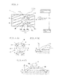
- FIG. 1 is an illustration showing a tread pattern of a studdable tire 1 according to an embodiment of the present invention.
- a tire having a directional pattern (a tire with a designated direction of rotation to be fitted on a vehicle in such a manner that the direction of rotation is consistent with the direction of vehicular advance).
- the vertical direction is the circumferential direction of the tire, and the horizontal direction the tire width direction.
- the lower side is the step-in side, and the upper side the kick-out side when the tire is rotating forward.
- circumferential grooves 3a to 3d Formed on a surface of the tread 2 of the studdable tire 1 are circumferential grooves 3a to 3d extending in a direction parallel to the circumferential direction of the tire, left-hand lug grooves 4a extending in an arc from upper left to lower right and intersecting the circumferential grooves 3a and 3b, and right-hand lug grooves 4b extending in an arc from upper right to lower left and intersecting the circumferential grooves 3c and 3d.
- a central land section 5 is defined by two circumferential grooves (hereinafter referred to as main grooves) 3b, 3c located on the inner side in the tire width direction. Disposed in the main groove 3b side and the main groove 3c side of the central land section 5 are unilaterally open grooves 5k extending in a direction intersecting the main grooves 3b, 3c, respectively, one end of which opens on the main grooves 3b, 3c, respectively, and the other end of which terminates within the central land section.
- First inner blocks 6a are defined by the main groove 3b, the circumferential groove (hereinafter referred to as a shoulder groove) 3a located on the outer side in the tire width direction, and the left-hand lug grooves 4a, and second inner blocks 6b are defined by the main groove 3c, the shoulder groove 3d and the right-hand lug grooves 4b.
- Left-hand shoulder blocks 7a are defined by the shoulder groove 3a and the left-hand lug grooves 4a
- right-hand shoulder blocks 7b are defined by the shoulder groove 3d and the right-hand lug grooves 4b.
- the left-hand lug grooves 4a and the right-hand lug grooves 4b as well as the left-hand blocks 6a, 7a and the right-hand blocks 6b, 7b have almost identical behavior (function).
- the lug grooves 4a, 4b are referred to as the lug grooves 4, the inner blocks 6a, 6b as the inner blocks 6, and the shoulder blocks 7a, 7b as the shoulder blocks 7.
- the inner blocks 6, and the shoulder blocks 7 are a plurality of sipes 8 extending in directions intersecting the circumferential direction of the tire. And formed in portions without the sipes 8 in the inner blocks 6 and the shoulder blocks 7 are stud holes 9 into which not-shown s spike pins are inserted.
- a group of ice-removal grooves 11A or a group of ice-removal grooves 11B, formed by a plurality of grooves, for removing ice powder occurring during the vehicle's travel on an ICE road surface out of the studdable tire 1 are disposed in the ring-shaped region R low , that is, the region R enclosed by two circles C 1 and C 2 of different radii having a center concentrical to the center of the stud hole 9.
- This arrangement restrains adhesion of the ice powder occurring during the vehicle's travel on an ICE road surface to the spike pin 10.
- the ice-removal grooves 11A are a group of ice-removal grooves disposed in the shoulder block 7, whereas the ice-removal grooves 11B are a group of ice-removal grooves disposed in the inner block 6.
- the radii r 1 and r 2 of the circles C 1 and C 2 depend on the radius of the stud hole 9 formed in the inner block 6 and the shoulder block 7, respectively.
- the ice-removal grooves 11A includes the first to third grooves 12 to 14 disposed in such a manner that they are spaced apart from each other in the region R of the shoulder block 7.
- the first and second grooves 12, 13 are both arc-shaped grooves in plan view, both ends of which terminate within the shoulder block 7 (intra-land groove), and are disposed on the kick-out side of the region R.
- the third groove 14 includes an intra-land groove portion 14a arc-shaped in plan view, both ends of which terminate within the shoulder block 7, and two communicating groove portions 14b which communicate both end portions of the intra-land groove portion 14a with the lug groove 4 located on the step-in side of the shoulder block 7.
- the communicating groove portions 14b are arranged on straight lines extending from the center of the arc constituting the intra-land groove portion 14a and passing through both ends of the arc.
- the first and second grooves 12, 13 are formed in positions symmetrical with respect to the straight line passing through the central portion of the third groove 14 and perpendicular to the lug groove 4.
- the radius r 1 of the inner circle C 1 it is preferable to set the radius r 1 of the inner circle C 1 such that the difference between the inner peripheral edges of the first and second grooves 12, 13 and the intra-land groove portion 14a and the outer peripheral edge of the stud hole 9 is about 0.5 to 1.5 mm. This is because too narrow an interval between the first and second grooves 12, 13 and the intra-land groove portion 14a and the stud hole 9 tends to cause the ice powder to remain around the spike pins.
- any attempt at widening the interval between the first and second grooves 12, 13 and the intra-land groove portion 14a and the stud hole 9 may result in a failure to locate the first and second grooves 12, 13 and the intra-land groove portion 14a within the ring-shaped region R low unless the groove widths of the first and second grooves 12, 13 and the intra-land groove portion 14a are narrowed.
- the radius r 2 of the outer circle C 2 is acceptable if it is equal to or less than the radius of the outer circle of the ring-shaped region R low that is made when the stud 10 is fitted. However, it is preferable that the radius r 2 of the circle C 2 is large enough to secure sufficient groove widths of the first and second grooves 12, 13 and the intra-land groove portion 14a.
- a groove may be added between the first groove 12 and the second groove 13, or otherwise the first groove 12 and the second groove 13 may be communicated with each other, thereby forming an arc-shaped groove.
- the rigidity of the shoulder blocks 7 it is preferable that no groove is placed between the first groove 12 and the second groove 13 as in the present embodiment.
- the intra-land groove portion 14a of the third groove 14 is divided into two arc-shaped grooves separate from each other, the rigidity of the shoulder blocks 7 can be raised.
- the intra-land groove portion 14a is shaped as a single arc-shaped groove as in the present embodiment.
- the groove width w of the first to third grooves 12 to 14 is 1.0 mm or more and not more than the difference (r 2 - r 1 ) between the radius r 1 of the circle C 1 and the radius r 2 of the circle C 2 , which is the upper limit of the groove width w.
- the groove depth h is preferably within a range of 0.2 mm to 1.5 mm, and the groove angle ⁇ within a range of 0 to 45 degrees. Note that the groove angle ⁇ is the angle formed between the straight line perpendicular to the tire tread surface and the groove walls of the grooves 12 to 14, as shown in FIGs. 4(a) to 4(c) .
- the groove width w is preferably 1.0 mm or more. Also, if the groove width w exceeds the upper limit, then the region where the first and second grooves 12, 13 and the intra-land groove portion 14a exist will extend outside the region R. This may result in a reduced rigidity of the shoulder blocks 7 as described above.
- the upper limit value of the groove width w should preferably be set at 3 mm. This is because the groove width w in excess of 3 mm will reduce the rigidity around the spike pin, thus narrowing the ring-shaped region R low . And, as a result, the region where the first and second grooves 12, 13 and the intra-land groove portion 14a exist may possibly extend outside the region R.
- the groove depth h is less than 0.2 mm, ice powder cannot be discharged out of the tire thoroughly because the groove width is too narrow to allow smooth movement of ice powder.
- the groove depth h is in excess of 1.5 mm, the ice powder can collect in the groove bottom with the result that the efficiency in the removal of ice powder drops. Therefore, it is preferable that the groove depth h is within a range of 0.2 mm to 1.5 mm.
- the ice-removal grooves 11B include the fourth to sixth grooves 15 to 17 disposed in such a manner that they are spaced apart from each other in the region R of the inner block 6.
- the fourth and fifth grooves 15, 16 are both arc-shaped grooves in plan view similar to the first and second grooves 12, 13, both ends of which terminate within the inner block 6, and are disposed on the kick-out side of the region R.
- the sixth groove 17 includes an intra-land groove portion 17a arc-shaped in plan view, both ends of which terminate within the shoulder block 7, and a communicating groove portion 17b which communicates the midportion of the intra-land groove portion 17a with the lug groove 4 located on the step-in side of the inner block 6.
- the communicating groove portion 17b is arranged on a straight line passing through the center of the arc forming the intra-land groove portion 14a and the center of the arc.
- the fourth and fifth grooves 15, 16 are formed in positions symmetrical with respect to the straight line passing through the midportion of the sixth groove 17 and perpendicular to the lug groove 4.
- the range of groove width w, the range of groove depth h thereof, and the range of groove angle ⁇ of the fourth to sixth grooves 15 to 17 disposed in the inner block 6 are the same as the range of groove width w, the range of groove depth h, and the range of groove angle ⁇ of the first to third grooves 12 to 14 disposed in the shoulder block 7.
- the groove width w, the groove depth h, and the groove angle ⁇ of the fourth to sixth grooves 15 to 17 disposed in the inner block 6 may be different from the groove width w, the groove depth h thereof, and the groove angle ⁇ of the first to third grooves 12 to 14 disposed in the shoulder block 7, respectively.
- the first to third grooves 12 to 14 are disposed on the step-in side and kick-out side of the region R of the shoulder block 7, which becomes the region R low after the fitting of the spike pins. Accordingly, the ice powder dug up by the spike pin is moved away from the spike pin and collected within the first and second grooves 12, 13 and the intra-land groove portion 14a of the third groove 14. Hence, it is possible to inhibit the ice powder from remaining around the spike pin and sticking to the spike pin. This will improve the performance of the studdable tire 1 on ICE road surfaces.
- first and second grooves 12, 13 and the intra-land groove portion 14a of the third groove 14 are disposed in positions that barely come in contact with the road surface. Therefore, adhesion of ice powder to the spike pins can be inhibited reliably without reducing the ground contact area of the shoulder blocks 7.
- the ice powder collected in the first and second grooves 12, 13 is discharged from within the first and second grooves 12, 13 directly to the outside of the tire as the studdable tire 1 rolls. And the ice powder collected in the intra-land groove portion 14a is discharged out of the tire directly or through the communicating groove portions 14b.
- the ice powder occurs mostly on the step-in side. But the occurred ice powder is first collected within the intra-land groove portion 14a of the third groove 14 disposed on the step-in side and then led into the lug groove 4 through the communicating groove portions 14b, and discharged out of the tire from the lug groove 4 and the shoulder groove 3a (or the shoulder groove 3d).
- the adhesion of ice powder to the spike pins can be effectively inhibited at the time of braking (locking). Therefore, the braking performance of the tire can be enhanced.
- the action of the fourth to sixth grooves 15 to 17 of the ice-removal grooves 11B disposed in the inner blocks 6 is the same as that of the first to third grooves 12 to 14 of the ice-removal grooves 11A, and so a repeated explanation thereof is omitted.
- the first and second grooves 12, 13 and the intra-land groove portion 14a as the intra-land grooves are disposed on the step-in side and kick-out side within the region R, which barely comes in contact with the ICE road surface K, on the shoulder block 7 defined by the shoulder groove 3a and the lug groove 4a or by the shoulder groove 3d and the lug groove 4b.
- this arrangement leads the ice powder occurring during vehicular travel on the ICE road surface into the intra-land grooves.
- the adhesion of ice powder to the spike pin 10 can be reliably inhibited without reducing the ground contact area substantively. This allows the spike pin 10 to penetrate the ice without fail, thus ensuring the steering stability performance of the tire on the ICE road surface.
- two communicating groove portions 14b are formed to communicate both end portions of the intra-land groove portion 14a with the lug groove 4 positioned on the step-in side of the shoulder block 7. Therefore, at the time of braking (locking) in BS control, the ice powder can be effectively discharged from the communicating grooves to the lug groove, thus enhancing the braking performance of the tire on the ICE road surface.
- the fourth and fifth grooves 15, 16 and the intra-land groove portion 17a as the intra-land grooves are disposed on the step-in side and kick-out side in the region R.
- a communicating groove portion 17b is formed to communicate the midportion of the intra-land groove portion 17a with the lug groove 4 positioned on the step-in side of the inner block. Therefore, the ice powder can be effectively removed into the lug groove while retaining the rigidity of the block.
- an ice-removal groove 18 provided with an arc-shaped intra-land groove portion 18a and a communicating groove portion 18b communicating the intra-land groove portion 18a with the lug groove 4 may be disposed on each of the step-in side and kick-out side in the region R around the stud hole 9.
- the ice-removal groove 18 disposed on the shoulder block 7 may be formed with two communicating groove portions 18b communicating both end portions of the intra-land groove portion 18a with the lug groove 4, and the ice-removal groove 18 disposed on the inner block 6 may be formed with a single communicating groove portion 18b communicating the midportion of the intra-land groove portion 18a with the lug groove 4. Then the ice powder may be effectively removed into the lug groove 4, and the performance at the time of braking can be improved.
- the groove depth of the first to sixth grooves 12 to 17 is fixed. But the groove depth may be made gradually shallower from the stud hole 9 side to the lug groove 4 side. By doing so, the ice powder can be expelled even more easily out of the tire.
- the first and second grooves 12, 13 are formed in positions symmetrical with respect to the straight line passing through the central portion of the third groove 14 (or the sixth groove 17) and perpendicular to the lug groove 4.
- the extension direction of the third groove 14 (or the sixth groove 17) may be set in the circumferential direction of the tire, and the first and second grooves 12, 13 (or the fourth and fifth grooves 15, 16) are formed in positions symmetrical with respect to a straight line parallel to the circumferential direction of the tire.
- the extension direction of the third groove 14 (or the sixth groove 17) only may be set in the circumferential direction of the tire.
- the groove length will be longer.
- the rigidity of the blocks may drop a little, but the ice powder can be expelled even more effectively into the lug groove 4.
- Studdable tires (present invention) having a group of ice-removal grooves disposed around each stud hole as shown in FIG. 1 and studdable tires (conventional type) without the group of ice-removal grooves were prepared.
- the tire size of the studdable tires used in the test was 205/55R16, and the number of stud holes per tire was 96 each.
- the braking performance was evaluated by measuring the time (braking time) from sudden braking to a complete stop of the test vehicle running at a constant speed of 20 km/h on an ICE road surface and indexing the inverse number of the braking time.
- the braking performance index (INDEX) in Table 1 is relative to 100, which represents the braking time of the Conventional Type studdable tire. The larger the value, the shorter the braking time and hence the better the braking performance is.
- the tire according to the present invention shows better braking performance and smaller variation in braking time than the conventional type tire. Therefore, it has been confirmed that the adhesion of ice powder occurring during vehicular travel to the spike pins can be effectively inhibited by disposing a group of ice-removal grooves around each stud hole as shown in FIG. 1 .
- the present invention can provide a studdable tire excelling in steering stability performance by effectively inhibiting the adhesion of ice powder occurring during vehicular travel on ICE road surfaces to the spike pins.
Landscapes
- Engineering & Computer Science (AREA)
- Mechanical Engineering (AREA)
- Tires In General (AREA)
Abstract
Description
- The present invention relates to a studdable tire having a tire tread formed with a plurality of stud holes into which spike pins are inserted.
- The studdable tire has been conventionally known as a winter tire having metallic studs (spike pins) driven into the land portions of the tread. As a vehicle fitted with these studdable tires runs on an ICE road surface, the tips of the studs dig into the road surface, thereby increasing the friction between the road surface and the tires. And this will ensure the steering stability performance on the ICE road surface.
- Also, there has been proposed, for winter tires, a method of alleviating external forces acting on spike pins, by providing, a slit of 3 to 7.5 mm in depth in such a way as to surround a stud hole on both sides or one side in the tire width direction to make the spike pins move together with the surrounding rubber so as to improve the anti-detachment property (see
Patent Document 1, for instance). - Patent Document 1: Japanese Unexamined Patent Application Publication No.
2008-230259 - As it is widely known, when a vehicle fitted with studdable tires runs on an ICE road surface, there occurs a phenomenon of ice powder having been dug up by the spike pins adhering to the peripheries of the spike pins. And if the ice powder adheres to the peripheries of the spike pins, the steering stability performance of the tires on ICE road surfaces may decline because penetration of the spike pins into the ice is hindered.
- The slits as disclosed in
Patent Document 1 reduce the external forces acting on the spike pins by opening and closing. Therefore, they can improve the anti-detachment property of the spike pins, but were not able to inhibit the adhesion of ice powder to the spike pins. - Also, as far as the present inventors know, there have been no effective technologies proposed for inhibiting the adhesion of ice powder to the spike pins.
- The present invention has been made in view of these conventional problems, and an object thereof is to provide a studdable tire ensuring a high steering stability performance by restraining adhesion of the ice powder occurring during vehicular travel on an ICE road surface to the spike pins.
- The present invention provides a studdable tire including a tire tread having circumferential grooves extending in a tire circumferential direction, lug grooves extending in a direction intersecting the circumferential grooves, land portions defined by the circumferential grooves and the lug grooves, stud holes formed in the land portions, in which the tire includes intra-land grooves, each having both ends thereof terminating within the land portion, the intra-land grooves being formed on each of a step-in side and a kick-out side of the land portion within a region enclosed by two circles of different radii having a center concentrical to a center of the stud hole on a land surface, and communicating grooves communicating the intra-land grooves with the lug grooves.
- It is to be understood that the foregoing summary of the invention does not necessarily recite all the features essential to the invention, and sub combinations of all these features may also be the invention.
-
-
FIG. 1 is an illustration showing an example of tread pattern of a studdable tire according to an embodiment of the present invention. -
FIGs. 2 (a) and 2 (b) are illustrations showing a region with low ground contact pressure around a spike pin. -
FIG. 3 is an illustration showing an arrangement of a group of ice-removal grooves disposed in a shoulder block. -
FIGs. 4(a) to 4(c) are illustrations showing shapes of the first to third grooves. -
FIG. 5 is an illustration showing an arrangement of a group of ice-removal grooves disposed in an inner block. -
FIGs. 6(a) and 6(b) are illustrations showing ice-removal grooves disposed on a non-directional tire. -
FIG. 1 is an illustration showing a tread pattern of astuddable tire 1 according to an embodiment of the present invention. In this embodiment, as thestuddable tire 1, a tire having a directional pattern (a tire with a designated direction of rotation to be fitted on a vehicle in such a manner that the direction of rotation is consistent with the direction of vehicular advance). In the figure, the vertical direction is the circumferential direction of the tire, and the horizontal direction the tire width direction. Also, the lower side is the step-in side, and the upper side the kick-out side when the tire is rotating forward. - Formed on a surface of the
tread 2 of thestuddable tire 1 arecircumferential grooves 3a to 3d extending in a direction parallel to the circumferential direction of the tire, left-hand lug grooves 4a extending in an arc from upper left to lower right and intersecting thecircumferential grooves hand lug grooves 4b extending in an arc from upper right to lower left and intersecting thecircumferential grooves - A
central land section 5 is defined by two circumferential grooves (hereinafter referred to as main grooves) 3b, 3c located on the inner side in the tire width direction. Disposed in themain groove 3b side and themain groove 3c side of thecentral land section 5 are unilaterallyopen grooves 5k extending in a direction intersecting themain grooves main grooves - First
inner blocks 6a are defined by themain groove 3b, the circumferential groove (hereinafter referred to as a shoulder groove) 3a located on the outer side in the tire width direction, and the left-hand lug grooves 4a, and secondinner blocks 6b are defined by themain groove 3c, theshoulder groove 3d and the right-hand lug grooves 4b. Left-hand shoulder blocks 7a are defined by theshoulder groove 3a and the left-hand lug grooves 4a, and right-hand shoulder blocks 7b are defined by theshoulder groove 3d and the right-hand lug grooves 4b. - In this embodiment, the left-
hand lug grooves 4a and the right-hand lug grooves 4b as well as the left-hand blocks hand blocks lug grooves inner blocks inner blocks 6, and theshoulder blocks shoulder blocks 7. - Formed on the tread surface side of the
central land section 5, theinner blocks 6, and theshoulder blocks 7 are a plurality ofsipes 8 extending in directions intersecting the circumferential direction of the tire. And formed in portions without thesipes 8 in theinner blocks 6 and theshoulder blocks 7 arestud holes 9 into which not-shown s spike pins are inserted. - When a vehicle with tires fitted with
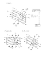
spike pins 10 is driven on an ICE road surface K, a ring-shaped region Rlow, as shown inFIGs. 2 (a) and 2(b) , which barely comes in contact with the ICE road surface K because of low ground contact pressure, is created around thespike pin 10. - In the present embodiment, as shown in
FIG. 3 andFIG. 5 , when thespike pin 10 is fitted into astud hole 9, a group of ice-removal grooves 11A or a group of ice-removal grooves 11B, formed by a plurality of grooves, for removing ice powder occurring during the vehicle's travel on an ICE road surface out of thestuddable tire 1, are disposed in the ring-shaped region Rlow, that is, the region R enclosed by two circles C1 and C2 of different radii having a center concentrical to the center of thestud hole 9. This arrangement restrains adhesion of the ice powder occurring during the vehicle's travel on an ICE road surface to thespike pin 10. Note that the ice-removal grooves 11A are a group of ice-removal grooves disposed in theshoulder block 7, whereas the ice-removal grooves 11B are a group of ice-removal grooves disposed in theinner block 6. - It is to be noted that the radii r1 and r2 of the circles C1 and C2 depend on the radius of the
stud hole 9 formed in theinner block 6 and theshoulder block 7, respectively. For example, when the radius of the middle part of thestud hole 9 is 2 mm, it is preferable that r1 = 4 mm and r2 = 6 mm or thereabout. - As shown in
FIG. 3 , the ice-removal grooves 11A includes the first tothird grooves 12 to 14 disposed in such a manner that they are spaced apart from each other in the region R of theshoulder block 7. - The first and
second grooves - The
third groove 14 includes anintra-land groove portion 14a arc-shaped in plan view, both ends of which terminate within theshoulder block 7, and two communicatinggroove portions 14b which communicate both end portions of theintra-land groove portion 14a with the lug groove 4 located on the step-in side of theshoulder block 7. - In the present embodiment, the communicating
groove portions 14b are arranged on straight lines extending from the center of the arc constituting theintra-land groove portion 14a and passing through both ends of the arc. - The first and
second grooves third groove 14 and perpendicular to the lug groove 4. - In doing so, it is preferable to set the radius r1 of the inner circle C1 such that the difference between the inner peripheral edges of the first and
second grooves intra-land groove portion 14a and the outer peripheral edge of thestud hole 9 is about 0.5 to 1.5 mm. This is because too narrow an interval between the first andsecond grooves intra-land groove portion 14a and thestud hole 9 tends to cause the ice powder to remain around the spike pins. - Conversely, any attempt at widening the interval between the first and
second grooves intra-land groove portion 14a and thestud hole 9 may result in a failure to locate the first andsecond grooves intra-land groove portion 14a within the ring-shaped region Rlow unless the groove widths of the first andsecond grooves intra-land groove portion 14a are narrowed. - It is to be noted that the radius r2 of the outer circle C2 is acceptable if it is equal to or less than the radius of the outer circle of the ring-shaped region Rlow that is made when the
stud 10 is fitted. However, it is preferable that the radius r2 of the circle C2 is large enough to secure sufficient groove widths of the first andsecond grooves intra-land groove portion 14a. - Also, to make the removal of ice powder easier, a groove may be added between the
first groove 12 and thesecond groove 13, or otherwise thefirst groove 12 and thesecond groove 13 may be communicated with each other, thereby forming an arc-shaped groove. However, if the rigidity of theshoulder blocks 7 is to be retained, it is preferable that no groove is placed between thefirst groove 12 and thesecond groove 13 as in the present embodiment. - Also, if the
intra-land groove portion 14a of thethird groove 14 is divided into two arc-shaped grooves separate from each other, the rigidity of theshoulder blocks 7 can be raised. However, to achieve an effective removal of ice powder at the time of braking (locking), it is preferable that theintra-land groove portion 14a is shaped as a single arc-shaped groove as in the present embodiment. - Also, as shown in
FIGs. 4 (a) to 4 (c) , it is preferable that the groove width w of the first tothird grooves 12 to 14 is 1.0 mm or more and not more than the difference (r2 - r1) between the radius r1 of the circle C1 and the radius r2 of the circle C2, which is the upper limit of the groove width w. Also, the groove depth h is preferably within a range of 0.2 mm to 1.5 mm, and the groove angle θ within a range of 0 to 45 degrees. Note that the groove angle θ is the angle formed between the straight line perpendicular to the tire tread surface and the groove walls of thegrooves 12 to 14, as shown inFIGs. 4(a) to 4(c) . - If the groove width w is less than 1.0 mm, ice powder cannot be discharged out of the tire thoroughly because the passage for removal of the ice powder dug up by the spike pins is narrow. Therefore the groove width w is preferably 1.0 mm or more. Also, if the groove width w exceeds the upper limit, then the region where the first and
second grooves intra-land groove portion 14a exist will extend outside the region R. This may result in a reduced rigidity of theshoulder blocks 7 as described above. - It is to be noted that when the width of the region R is r2 - r1 ≧ 3 mm, the upper limit value of the groove width w should preferably be set at 3 mm. This is because the groove width w in excess of 3 mm will reduce the rigidity around the spike pin, thus narrowing the ring-shaped region Rlow. And, as a result, the region where the first and
second grooves intra-land groove portion 14a exist may possibly extend outside the region R. - If the groove depth h is less than 0.2 mm, ice powder cannot be discharged out of the tire thoroughly because the groove width is too narrow to allow smooth movement of ice powder. On the other hand, if the groove depth h is in excess of 1.5 mm, the ice powder can collect in the groove bottom with the result that the efficiency in the removal of ice powder drops. Therefore, it is preferable that the groove depth h is within a range of 0.2 mm to 1.5 mm.
- Also, the groove angle θ should preferably be 45 degrees or less. This is because the groove angle θ in excess of 45° makes the groove depth shallower and reduces the groove volume to a half or less of that when θ = 0° (the wall surface being vertical). And this in turn makes it impossible to discharge the ice power out of the tire thoroughly.
- As shown in
FIG. 5 , the ice-removal grooves 11B include the fourth tosixth grooves 15 to 17 disposed in such a manner that they are spaced apart from each other in the region R of theinner block 6. - The fourth and
fifth grooves second grooves inner block 6, and are disposed on the kick-out side of the region R. - The
sixth groove 17 includes anintra-land groove portion 17a arc-shaped in plan view, both ends of which terminate within theshoulder block 7, and a communicatinggroove portion 17b which communicates the midportion of theintra-land groove portion 17a with the lug groove 4 located on the step-in side of theinner block 6. In the present embodiment, the communicatinggroove portion 17b is arranged on a straight line passing through the center of the arc forming theintra-land groove portion 14a and the center of the arc. - The fourth and
fifth grooves sixth groove 17 and perpendicular to the lug groove 4. - The range of groove width w, the range of groove depth h thereof, and the range of groove angle θ of the fourth to
sixth grooves 15 to 17 disposed in theinner block 6 are the same as the range of groove width w, the range of groove depth h, and the range of groove angle θ of the first tothird grooves 12 to 14 disposed in theshoulder block 7. - However, the groove width w, the groove depth h, and the groove angle θ of the fourth to
sixth grooves 15 to 17 disposed in theinner block 6 may be different from the groove width w, the groove depth h thereof, and the groove angle θ of the first tothird grooves 12 to 14 disposed in theshoulder block 7, respectively. - Now, a description is given of the action of the ice-
removal grooves 11A disposed in the shoulder blocks 7. - When the tires fitted with spike pins in the stud holes 9 run on the ICE road surface K, ice powder occurs as the ICE road surface K is dug up by the spike pins. If the ice-
removal grooves 11A are not formed, the occurred ice powder will remain within the region Rlow around the spike pin as shown inFIG. 2 with the result that the ice powder adheres to the periphery of the spike pin. - In the present embodiment, the first to
third grooves 12 to 14 are disposed on the step-in side and kick-out side of the region R of theshoulder block 7, which becomes the region Rlow after the fitting of the spike pins. Accordingly, the ice powder dug up by the spike pin is moved away from the spike pin and collected within the first andsecond grooves intra-land groove portion 14a of thethird groove 14. Hence, it is possible to inhibit the ice powder from remaining around the spike pin and sticking to the spike pin. This will improve the performance of thestuddable tire 1 on ICE road surfaces. - Also, the first and
second grooves intra-land groove portion 14a of thethird groove 14 are disposed in positions that barely come in contact with the road surface. Therefore, adhesion of ice powder to the spike pins can be inhibited reliably without reducing the ground contact area of the shoulder blocks 7. - It should be noted that the ice powder collected in the first and
second grooves second grooves studdable tire 1 rolls. And the ice powder collected in theintra-land groove portion 14a is discharged out of the tire directly or through the communicatinggroove portions 14b. - On the other hand, at the time of braking (locking) the tires, the ice powder occurs mostly on the step-in side. But the occurred ice powder is first collected within the
intra-land groove portion 14a of thethird groove 14 disposed on the step-in side and then led into the lug groove 4 through the communicatinggroove portions 14b, and discharged out of the tire from the lug groove 4 and theshoulder groove 3a (or theshoulder groove 3d). - With the
third groove 14 having the communicatinggroove portions 14b communicating to the lug groove 4 disposed on the step-in side of theshoulder block 7 like this, the adhesion of ice powder to the spike pins can be effectively inhibited at the time of braking (locking). Therefore, the braking performance of the tire can be enhanced. - The action of the fourth to
sixth grooves 15 to 17 of the ice-removal grooves 11B disposed in theinner blocks 6 is the same as that of the first tothird grooves 12 to 14 of the ice-removal grooves 11A, and so a repeated explanation thereof is omitted. - Thus, in the present embodiment, the first and
second grooves intra-land groove portion 14a as the intra-land grooves are disposed on the step-in side and kick-out side within the region R, which barely comes in contact with the ICE road surface K, on theshoulder block 7 defined by theshoulder groove 3a and thelug groove 4a or by theshoulder groove 3d and thelug groove 4b. And this arrangement leads the ice powder occurring during vehicular travel on the ICE road surface into the intra-land grooves. As a result, the adhesion of ice powder to thespike pin 10 can be reliably inhibited without reducing the ground contact area substantively. This allows thespike pin 10 to penetrate the ice without fail, thus ensuring the steering stability performance of the tire on the ICE road surface. - Also, two communicating
groove portions 14b are formed to communicate both end portions of theintra-land groove portion 14a with the lug groove 4 positioned on the step-in side of theshoulder block 7. Therefore, at the time of braking (locking) in BS control, the ice powder can be effectively discharged from the communicating grooves to the lug groove, thus enhancing the braking performance of the tire on the ICE road surface. - Also, on the
inner block 6 defined by themain groove 3b, theshoulder groove 3a and thelug grooves 4a, or by themain groove 3c, theshoulder groove 3d and thelug grooves 4b, the fourth andfifth grooves intra-land groove portion 17a as the intra-land grooves are disposed on the step-in side and kick-out side in the region R. At the same time, a communicatinggroove portion 17b is formed to communicate the midportion of theintra-land groove portion 17a with the lug groove 4 positioned on the step-in side of the inner block. Therefore, the ice powder can be effectively removed into the lug groove while retaining the rigidity of the block. - In the foregoing, the invention has been described with reference to specific embodiments thereof. However, the technical scope of this invention is not to be considered as limited to those embodiments. It will be evident to those skilled in the art that various modifications and changes may be made thereto without departing from the broader spirit and scope of the invention. It will also be evident from the scope of the appended claims that all such modifications are intended to be included within the technical scope of this invention.
- In the foregoing embodiment, a description has been given of the
studdable tire 1 having a directional pattern. Yet, in the case of astuddable tire 1 having a pattern that allows use in either direction of rotation (tire with no designated direction of rotation), there is no distinction between the kick-out side and the step-in side. Hence, as shown inFIGs. 6(a) and 6(b) , an ice-removal groove 18 provided with an arc-shapedintra-land groove portion 18a and a communicatinggroove portion 18b communicating theintra-land groove portion 18a with the lug groove 4 may be disposed on each of the step-in side and kick-out side in the region R around thestud hole 9. - Also, in regard to the communicating
groove portion 18b, in the same way as with the tire having a directional pattern, the ice-removal groove 18 disposed on theshoulder block 7 may be formed with two communicatinggroove portions 18b communicating both end portions of theintra-land groove portion 18a with the lug groove 4, and the ice-removal groove 18 disposed on theinner block 6 may be formed with a single communicatinggroove portion 18b communicating the midportion of theintra-land groove portion 18a with the lug groove 4. Then the ice powder may be effectively removed into the lug groove 4, and the performance at the time of braking can be improved. - It is to be noted that in the foregoing embodiment, a description has been given of the
studdable tire 1 having a tread pattern with thecentral land section 5, theinner blocks 6, and theshoulder blocks 7, but this is not a limitation. The present invention may also be applicable to studdable tires having other tread patterns such as one with a series of blocks in thecentral land section 5. - Also, in the foregoing embodiment, the groove depth of the first to
sixth grooves 12 to 17 is fixed. But the groove depth may be made gradually shallower from thestud hole 9 side to the lug groove 4 side. By doing so, the ice powder can be expelled even more easily out of the tire. - Also, in the foregoing embodiment, the first and
second grooves 12, 13 (or the fourth andfifth grooves 15, 16) are formed in positions symmetrical with respect to the straight line passing through the central portion of the third groove 14 (or the sixth groove 17) and perpendicular to the lug groove 4. However, the extension direction of the third groove 14 (or the sixth groove 17) may be set in the circumferential direction of the tire, and the first andsecond grooves 12, 13 (or the fourth andfifth grooves 15, 16) are formed in positions symmetrical with respect to a straight line parallel to the circumferential direction of the tire. - Also, the extension direction of the third groove 14 (or the sixth groove 17) only may be set in the circumferential direction of the tire. When the extension direction of the third groove 14 (or the sixth groove 17) only is set in the circumferential direction of the tire, the groove length will be longer. As a result, the rigidity of the blocks may drop a little, but the ice powder can be expelled even more effectively into the lug groove 4.
- Studdable tires (present invention) having a group of ice-removal grooves disposed around each stud hole as shown in
FIG. 1 and studdable tires (conventional type) without the group of ice-removal grooves were prepared. An investigation was made regarding the braking performance of the test vehicles fitted with tires having spike pins driven into the stud holes. The results are shown in Table 1. - The tire size of the studdable tires used in the test was 205/55R16, and the number of stud holes per tire was 96 each.
- The braking performance was evaluated by measuring the time (braking time) from sudden braking to a complete stop of the test vehicle running at a constant speed of 20 km/h on an ICE road surface and indexing the inverse number of the braking time. The braking performance index (INDEX) in Table 1 is relative to 100, which represents the braking time of the Conventional Type studdable tire. The larger the value, the shorter the braking time and hence the better the braking performance is.
- Also, the braking test was repeated five times, and the variation in braking time (standard deviation σ) was also investigated. The smaller the value of σ, the smaller the variation in the braking time.
[Table 1] Conventional Type Present Invention INDEX 100 108 N5 σ (sec) 0.182 0.107 - As is evident from Table 1, the tire according to the present invention shows better braking performance and smaller variation in braking time than the conventional type tire. Therefore, it has been confirmed that the adhesion of ice powder occurring during vehicular travel to the spike pins can be effectively inhibited by disposing a group of ice-removal grooves around each stud hole as shown in
FIG. 1 . - As described thus for, the present invention can provide a studdable tire excelling in steering stability performance by effectively inhibiting the adhesion of ice powder occurring during vehicular travel on ICE road surfaces to the spike pins.
-
- 1
- studdable tire
- 2
- tread
- 3a-3d
- circumferential groove
- 4, 4a, 4b
- lug groove
- 5
- central land section
- 6, 6a, 6b
- inner block
- 7, 7a, 7b
- shoulder block
- 8
- sipe
- 9
- stud hole
- 10
- spike pin
- 11A, 11B
- ice-removal grooves
- 12-17
- first to sixth grooves
- 14a, 17a
- intra-land groove portions
- 14b, 17b
- communicating groove portions
- K
- ICE road surface
Claims (4)
- A studdable tire comprising a tire tread having circumferential grooves extending in a tire circumferential direction, lug grooves extending in a direction intersecting the circumferential grooves, land portions defined by the circumferential grooves and the lug grooves, and stud holes formed in the land portions,
wherein the tire includes intra-land grooves, each of both ends thereof terminating within the land portion, the intra-land grooves being formed on each of a step-in side and a kick-out side of the land portion within a region enclosed by two circles of different radii each having a center concentrical to a center of the stud hole on a surface of the land portion, and communicating grooves communicating the intra-land grooves with the lug grooves. - The studdable tire according to claim 1, wherein the tire has a directional pattern and the communicating grooves are formed only for intra-land grooves formed on the setp-in side among the intra-land grooves.
- The studdable tire according to claim 1, wherein the tire has a pattern usable in either direction of rotation and the communicating grooves are formed for both of the intra-land grooves on the step-in side and the intra-land grooves on the kick-out side.
- The studdable tire according to any of claims 1 to 3, wherein the communicating groove is formed at each end of the intra-land groove in a case where the land portions having the stud holes are shoulder land portions provided in a shoulder portion of the tire, and the communicating groove is formed in a mid portion in a width direction of the intra-land groove in a case where the land portions having the stud holes are land portions located inside in a tire width direction of the shoulder portion.
Applications Claiming Priority (2)
| Application Number | Priority Date | Filing Date | Title |
|---|---|---|---|
| JP2013022207A JP5571207B1 (en) | 2013-02-07 | 2013-02-07 | Studded tires |
| PCT/JP2014/052731 WO2014123181A1 (en) | 2013-02-07 | 2014-02-06 | Studdable tire |
Publications (3)
| Publication Number | Publication Date |
|---|---|
| EP2955037A1 true EP2955037A1 (en) | 2015-12-16 |
| EP2955037A4 EP2955037A4 (en) | 2016-11-02 |
| EP2955037B1 EP2955037B1 (en) | 2018-07-11 |
Family
ID=51299772
Family Applications (1)
| Application Number | Title | Priority Date | Filing Date |
|---|---|---|---|
| EP14748611.2A Not-in-force EP2955037B1 (en) | 2013-02-07 | 2014-02-06 | Studdable tire |
Country Status (4)
| Country | Link |
|---|---|
| EP (1) | EP2955037B1 (en) |
| JP (1) | JP5571207B1 (en) |
| RU (1) | RU2621824C2 (en) |
| WO (1) | WO2014123181A1 (en) |
Cited By (7)
| Publication number | Priority date | Publication date | Assignee | Title |
|---|---|---|---|---|
| WO2018202341A1 (en) * | 2017-05-02 | 2018-11-08 | Continental Reifen Deutschland Gmbh | Vehicle tyres for a vehicle |
| CN109747345A (en) * | 2017-11-08 | 2019-05-14 | 东洋橡胶工业株式会社 | Pneumatic tires |
| US10464377B2 (en) | 2015-10-08 | 2019-11-05 | Sumitomo Rubber Industries, Ltd. | Winter tire |
| WO2020012281A1 (en) * | 2018-07-13 | 2020-01-16 | Pirelli Tyre S.P.A. | Studded tyre for vehicle wheels |
| RU2731835C2 (en) * | 2016-04-28 | 2020-09-08 | Дзе Йокогама Раббер Ко., Лтд. | Stud pin and pneumatic tire |
| RU2773557C1 (en) * | 2018-07-13 | 2022-06-06 | Пирелли Тайр С.П.А. | Studded tyre for vehicle wheels |
| EP4023465A4 (en) * | 2019-08-30 | 2023-10-04 | The Yokohama Rubber Co., Ltd. | Pneumatic tire and tire molding mold |
Families Citing this family (7)
| Publication number | Priority date | Publication date | Assignee | Title |
|---|---|---|---|---|
| JP6258041B2 (en) * | 2014-01-16 | 2018-01-10 | 株式会社ブリヂストン | Studded tires |
| DE102014225047A1 (en) * | 2014-12-05 | 2016-06-09 | Continental Reifen Deutschland Gmbh | Vehicle tires |
| DE102015221117A1 (en) | 2015-10-29 | 2017-05-04 | Continental Reifen Deutschland Gmbh | Vehicle tires |
| DE102015221118A1 (en) | 2015-10-29 | 2017-05-04 | Continental Reifen Deutschland Gmbh | Vehicle tires |
| JP6825434B2 (en) * | 2017-03-16 | 2021-02-03 | 住友ゴム工業株式会社 | tire |
| JP7151304B2 (en) * | 2018-09-14 | 2022-10-12 | 横浜ゴム株式会社 | Pneumatic tires and stud tires |
| JP7310434B2 (en) * | 2019-08-19 | 2023-07-19 | 住友ゴム工業株式会社 | tire |
Family Cites Families (6)
| Publication number | Priority date | Publication date | Assignee | Title |
|---|---|---|---|---|
| JP5098383B2 (en) | 2007-03-16 | 2012-12-12 | 横浜ゴム株式会社 | Pneumatic stud tire |
| FR2931729B1 (en) * | 2008-06-03 | 2010-07-30 | Michelin Soc Tech | PNEUMATIC FOR ICE TRUCK |
| FR2931728B1 (en) * | 2008-06-03 | 2010-07-30 | Michelin Soc Tech | PNEUMATIC FOR ICE TRUCK |
| DE102009044547A1 (en) * | 2009-11-16 | 2011-05-19 | Continental Reifen Deutschland Gmbh | Tread pattern of a pneumatic vehicle tire |
| KR20110066417A (en) * | 2009-12-11 | 2011-06-17 | 한국타이어 주식회사 | Stud tires |
| RU2579386C2 (en) * | 2011-05-03 | 2016-04-10 | Александр Васильевич Корниенко | Antiskid stud |
-
2013
- 2013-02-07 JP JP2013022207A patent/JP5571207B1/en not_active Expired - Fee Related
-
2014
- 2014-02-06 WO PCT/JP2014/052731 patent/WO2014123181A1/en not_active Ceased
- 2014-02-06 EP EP14748611.2A patent/EP2955037B1/en not_active Not-in-force
- 2014-02-06 RU RU2015137830A patent/RU2621824C2/en active
Cited By (14)
| Publication number | Priority date | Publication date | Assignee | Title |
|---|---|---|---|---|
| US10464377B2 (en) | 2015-10-08 | 2019-11-05 | Sumitomo Rubber Industries, Ltd. | Winter tire |
| RU2731835C2 (en) * | 2016-04-28 | 2020-09-08 | Дзе Йокогама Раббер Ко., Лтд. | Stud pin and pneumatic tire |
| WO2018202341A1 (en) * | 2017-05-02 | 2018-11-08 | Continental Reifen Deutschland Gmbh | Vehicle tyres for a vehicle |
| CN109747345A (en) * | 2017-11-08 | 2019-05-14 | 东洋橡胶工业株式会社 | Pneumatic tires |
| RU2773557C1 (en) * | 2018-07-13 | 2022-06-06 | Пирелли Тайр С.П.А. | Studded tyre for vehicle wheels |
| CN112351896A (en) * | 2018-07-13 | 2021-02-09 | 倍耐力轮胎股份公司 | Studded tyre for vehicle wheels |
| WO2020012281A1 (en) * | 2018-07-13 | 2020-01-16 | Pirelli Tyre S.P.A. | Studded tyre for vehicle wheels |
| EP4070971A1 (en) * | 2018-07-13 | 2022-10-12 | Pirelli Tyre S.p.A. | Studded tyre for vehicle wheels |
| EP4074523A1 (en) * | 2018-07-13 | 2022-10-19 | Pirelli Tyre S.p.A. | Studded tyre for vehicle wheels |
| CN116330893A (en) * | 2018-07-13 | 2023-06-27 | 倍耐力轮胎股份公司 | Tyre with anti-skid nail |
| RU2846224C2 (en) * | 2018-07-13 | 2025-09-02 | Пирелли Тайр С.П.А. | Studded tyre for vehicle wheels |
| RU2846296C2 (en) * | 2018-07-13 | 2025-09-03 | Пирелли Тайр С.П.А. | Studded tyre for vehicle wheels |
| EP4023465A4 (en) * | 2019-08-30 | 2023-10-04 | The Yokohama Rubber Co., Ltd. | Pneumatic tire and tire molding mold |
| US12280617B2 (en) | 2019-08-30 | 2025-04-22 | The Yokohama Rubber Co., Ltd. | Pneumatic tire and tire molding mold |
Also Published As
| Publication number | Publication date |
|---|---|
| EP2955037B1 (en) | 2018-07-11 |
| RU2621824C2 (en) | 2017-06-07 |
| RU2015137830A (en) | 2017-03-14 |
| JP5571207B1 (en) | 2014-08-13 |
| WO2014123181A1 (en) | 2014-08-14 |
| EP2955037A4 (en) | 2016-11-02 |
| JP2014151740A (en) | 2014-08-25 |
Similar Documents
| Publication | Publication Date | Title |
|---|---|---|
| EP2955037B1 (en) | Studdable tire | |
| US10369846B2 (en) | Tread for heavy vehicle tire | |
| EP3162594B1 (en) | Pneumatic tire | |
| EP3156259B1 (en) | Tire | |
| EP3095619B1 (en) | Studdable tire | |
| US20170001478A1 (en) | Tread for heavy-goods vehicle tire | |
| US20130000805A1 (en) | Pneumatic tire | |
| EP2692543B1 (en) | Pneumatic tire | |
| EP3006233A1 (en) | Tire | |
| EP2527164A1 (en) | Pneumatic tire | |
| CN102442165B (en) | Pneumatic tire | |
| US10814676B2 (en) | Tread for heavy truck winter tire | |
| CA2895469A1 (en) | A tyre for control of road-holding | |
| US20150375572A1 (en) | Pneumatic Tire | |
| EP3020575B1 (en) | Pneumatic tire | |
| JP5665611B2 (en) | Pneumatic tire | |
| EP3444129A1 (en) | Pneumatic tire | |
| US10166820B2 (en) | Pneumatic tire | |
| CA2911630C (en) | Pneumatic tire | |
| EP3015289B1 (en) | Pneumatic tire | |
| EP4400335B1 (en) | Pneumatic tire | |
| JP6777521B2 (en) | Pneumatic tires | |
| JP6777520B2 (en) | Pneumatic tires | |
| US20110284141A1 (en) | Rotating Sipe | |
| JP7218246B2 (en) | tire |
Legal Events
| Date | Code | Title | Description |
|---|---|---|---|
| PUAI | Public reference made under article 153(3) epc to a published international application that has entered the european phase |
Free format text: ORIGINAL CODE: 0009012 |
|
| 17P | Request for examination filed |
Effective date: 20150727 |
|
| AK | Designated contracting states |
Kind code of ref document: A1 Designated state(s): AL AT BE BG CH CY CZ DE DK EE ES FI FR GB GR HR HU IE IS IT LI LT LU LV MC MK MT NL NO PL PT RO RS SE SI SK SM TR |
|
| AX | Request for extension of the european patent |
Extension state: BA ME |
|
| DAX | Request for extension of the european patent (deleted) | ||
| A4 | Supplementary search report drawn up and despatched |
Effective date: 20160930 |
|
| RIC1 | Information provided on ipc code assigned before grant |
Ipc: B60C 11/03 20060101ALI20160926BHEP Ipc: B60C 11/12 20060101ALI20160926BHEP Ipc: B60C 11/16 20060101AFI20160926BHEP Ipc: B60C 11/04 20060101ALI20160926BHEP |
|
| GRAP | Despatch of communication of intention to grant a patent |
Free format text: ORIGINAL CODE: EPIDOSNIGR1 |
|
| STAA | Information on the status of an ep patent application or granted ep patent |
Free format text: STATUS: GRANT OF PATENT IS INTENDED |
|
| RIC1 | Information provided on ipc code assigned before grant |
Ipc: B60C 11/12 20060101ALI20171222BHEP Ipc: B60C 11/16 20060101AFI20171222BHEP Ipc: B60C 11/04 20060101ALI20171222BHEP Ipc: B60C 11/03 20060101ALI20171222BHEP |
|
| INTG | Intention to grant announced |
Effective date: 20180131 |
|
| GRAS | Grant fee paid |
Free format text: ORIGINAL CODE: EPIDOSNIGR3 |
|
| GRAA | (expected) grant |
Free format text: ORIGINAL CODE: 0009210 |
|
| STAA | Information on the status of an ep patent application or granted ep patent |
Free format text: STATUS: THE PATENT HAS BEEN GRANTED |
|
| AK | Designated contracting states |
Kind code of ref document: B1 Designated state(s): AL AT BE BG CH CY CZ DE DK EE ES FI FR GB GR HR HU IE IS IT LI LT LU LV MC MK MT NL NO PL PT RO RS SE SI SK SM TR |
|
| REG | Reference to a national code |
Ref country code: GB Ref legal event code: FG4D |
|
| REG | Reference to a national code |
Ref country code: CH Ref legal event code: EP |
|
| REG | Reference to a national code |
Ref country code: AT Ref legal event code: REF Ref document number: 1016490 Country of ref document: AT Kind code of ref document: T Effective date: 20180715 |
|
| REG | Reference to a national code |
Ref country code: IE Ref legal event code: FG4D |
|
| REG | Reference to a national code |
Ref country code: DE Ref legal event code: R096 Ref document number: 602014028319 Country of ref document: DE |
|
| REG | Reference to a national code |
Ref country code: NL Ref legal event code: MP Effective date: 20180711 |
|
| REG | Reference to a national code |
Ref country code: LT Ref legal event code: MG4D |
|
| REG | Reference to a national code |
Ref country code: AT Ref legal event code: MK05 Ref document number: 1016490 Country of ref document: AT Kind code of ref document: T Effective date: 20180711 |
|
| PG25 | Lapsed in a contracting state [announced via postgrant information from national office to epo] |
Ref country code: NL Free format text: LAPSE BECAUSE OF FAILURE TO SUBMIT A TRANSLATION OF THE DESCRIPTION OR TO PAY THE FEE WITHIN THE PRESCRIBED TIME-LIMIT Effective date: 20180711 |
|
| PG25 | Lapsed in a contracting state [announced via postgrant information from national office to epo] |
Ref country code: GR Free format text: LAPSE BECAUSE OF FAILURE TO SUBMIT A TRANSLATION OF THE DESCRIPTION OR TO PAY THE FEE WITHIN THE PRESCRIBED TIME-LIMIT Effective date: 20181012 Ref country code: RS Free format text: LAPSE BECAUSE OF FAILURE TO SUBMIT A TRANSLATION OF THE DESCRIPTION OR TO PAY THE FEE WITHIN THE PRESCRIBED TIME-LIMIT Effective date: 20180711 Ref country code: AT Free format text: LAPSE BECAUSE OF FAILURE TO SUBMIT A TRANSLATION OF THE DESCRIPTION OR TO PAY THE FEE WITHIN THE PRESCRIBED TIME-LIMIT Effective date: 20180711 Ref country code: PL Free format text: LAPSE BECAUSE OF FAILURE TO SUBMIT A TRANSLATION OF THE DESCRIPTION OR TO PAY THE FEE WITHIN THE PRESCRIBED TIME-LIMIT Effective date: 20180711 Ref country code: IS Free format text: LAPSE BECAUSE OF FAILURE TO SUBMIT A TRANSLATION OF THE DESCRIPTION OR TO PAY THE FEE WITHIN THE PRESCRIBED TIME-LIMIT Effective date: 20181111 Ref country code: NO Free format text: LAPSE BECAUSE OF FAILURE TO SUBMIT A TRANSLATION OF THE DESCRIPTION OR TO PAY THE FEE WITHIN THE PRESCRIBED TIME-LIMIT Effective date: 20181011 Ref country code: SE Free format text: LAPSE BECAUSE OF FAILURE TO SUBMIT A TRANSLATION OF THE DESCRIPTION OR TO PAY THE FEE WITHIN THE PRESCRIBED TIME-LIMIT Effective date: 20180711 Ref country code: FI Free format text: LAPSE BECAUSE OF FAILURE TO SUBMIT A TRANSLATION OF THE DESCRIPTION OR TO PAY THE FEE WITHIN THE PRESCRIBED TIME-LIMIT Effective date: 20180711 Ref country code: LT Free format text: LAPSE BECAUSE OF FAILURE TO SUBMIT A TRANSLATION OF THE DESCRIPTION OR TO PAY THE FEE WITHIN THE PRESCRIBED TIME-LIMIT Effective date: 20180711 Ref country code: BG Free format text: LAPSE BECAUSE OF FAILURE TO SUBMIT A TRANSLATION OF THE DESCRIPTION OR TO PAY THE FEE WITHIN THE PRESCRIBED TIME-LIMIT Effective date: 20181011 |
|
| PG25 | Lapsed in a contracting state [announced via postgrant information from national office to epo] |
Ref country code: LV Free format text: LAPSE BECAUSE OF FAILURE TO SUBMIT A TRANSLATION OF THE DESCRIPTION OR TO PAY THE FEE WITHIN THE PRESCRIBED TIME-LIMIT Effective date: 20180711 Ref country code: AL Free format text: LAPSE BECAUSE OF FAILURE TO SUBMIT A TRANSLATION OF THE DESCRIPTION OR TO PAY THE FEE WITHIN THE PRESCRIBED TIME-LIMIT Effective date: 20180711 Ref country code: ES Free format text: LAPSE BECAUSE OF FAILURE TO SUBMIT A TRANSLATION OF THE DESCRIPTION OR TO PAY THE FEE WITHIN THE PRESCRIBED TIME-LIMIT Effective date: 20180711 Ref country code: HR Free format text: LAPSE BECAUSE OF FAILURE TO SUBMIT A TRANSLATION OF THE DESCRIPTION OR TO PAY THE FEE WITHIN THE PRESCRIBED TIME-LIMIT Effective date: 20180711 |
|
| REG | Reference to a national code |
Ref country code: DE Ref legal event code: R097 Ref document number: 602014028319 Country of ref document: DE |
|
| PG25 | Lapsed in a contracting state [announced via postgrant information from national office to epo] |
Ref country code: IT Free format text: LAPSE BECAUSE OF FAILURE TO SUBMIT A TRANSLATION OF THE DESCRIPTION OR TO PAY THE FEE WITHIN THE PRESCRIBED TIME-LIMIT Effective date: 20180711 Ref country code: EE Free format text: LAPSE BECAUSE OF FAILURE TO SUBMIT A TRANSLATION OF THE DESCRIPTION OR TO PAY THE FEE WITHIN THE PRESCRIBED TIME-LIMIT Effective date: 20180711 Ref country code: CZ Free format text: LAPSE BECAUSE OF FAILURE TO SUBMIT A TRANSLATION OF THE DESCRIPTION OR TO PAY THE FEE WITHIN THE PRESCRIBED TIME-LIMIT Effective date: 20180711 Ref country code: RO Free format text: LAPSE BECAUSE OF FAILURE TO SUBMIT A TRANSLATION OF THE DESCRIPTION OR TO PAY THE FEE WITHIN THE PRESCRIBED TIME-LIMIT Effective date: 20180711 |
|
| PLBE | No opposition filed within time limit |
Free format text: ORIGINAL CODE: 0009261 |
|
| STAA | Information on the status of an ep patent application or granted ep patent |
Free format text: STATUS: NO OPPOSITION FILED WITHIN TIME LIMIT |
|
| PG25 | Lapsed in a contracting state [announced via postgrant information from national office to epo] |
Ref country code: SK Free format text: LAPSE BECAUSE OF FAILURE TO SUBMIT A TRANSLATION OF THE DESCRIPTION OR TO PAY THE FEE WITHIN THE PRESCRIBED TIME-LIMIT Effective date: 20180711 Ref country code: DK Free format text: LAPSE BECAUSE OF FAILURE TO SUBMIT A TRANSLATION OF THE DESCRIPTION OR TO PAY THE FEE WITHIN THE PRESCRIBED TIME-LIMIT Effective date: 20180711 Ref country code: SM Free format text: LAPSE BECAUSE OF FAILURE TO SUBMIT A TRANSLATION OF THE DESCRIPTION OR TO PAY THE FEE WITHIN THE PRESCRIBED TIME-LIMIT Effective date: 20180711 |
|
| 26N | No opposition filed |
Effective date: 20190412 |
|
| PG25 | Lapsed in a contracting state [announced via postgrant information from national office to epo] |
Ref country code: SI Free format text: LAPSE BECAUSE OF FAILURE TO SUBMIT A TRANSLATION OF THE DESCRIPTION OR TO PAY THE FEE WITHIN THE PRESCRIBED TIME-LIMIT Effective date: 20180711 |
|
| REG | Reference to a national code |
Ref country code: CH Ref legal event code: PL |
|
| GBPC | Gb: european patent ceased through non-payment of renewal fee |
Effective date: 20190206 |
|
| PG25 | Lapsed in a contracting state [announced via postgrant information from national office to epo] |
Ref country code: MC Free format text: LAPSE BECAUSE OF FAILURE TO SUBMIT A TRANSLATION OF THE DESCRIPTION OR TO PAY THE FEE WITHIN THE PRESCRIBED TIME-LIMIT Effective date: 20180711 Ref country code: LU Free format text: LAPSE BECAUSE OF NON-PAYMENT OF DUE FEES Effective date: 20190206 |
|
| REG | Reference to a national code |
Ref country code: BE Ref legal event code: MM Effective date: 20190228 |
|
| REG | Reference to a national code |
Ref country code: IE Ref legal event code: MM4A |
|
| PG25 | Lapsed in a contracting state [announced via postgrant information from national office to epo] |
Ref country code: LI Free format text: LAPSE BECAUSE OF NON-PAYMENT OF DUE FEES Effective date: 20190228 Ref country code: CH Free format text: LAPSE BECAUSE OF NON-PAYMENT OF DUE FEES Effective date: 20190228 |
|
| PG25 | Lapsed in a contracting state [announced via postgrant information from national office to epo] |
Ref country code: GB Free format text: LAPSE BECAUSE OF NON-PAYMENT OF DUE FEES Effective date: 20190206 Ref country code: IE Free format text: LAPSE BECAUSE OF NON-PAYMENT OF DUE FEES Effective date: 20190206 |
|
| PG25 | Lapsed in a contracting state [announced via postgrant information from national office to epo] |
Ref country code: BE Free format text: LAPSE BECAUSE OF NON-PAYMENT OF DUE FEES Effective date: 20190228 |
|
| PG25 | Lapsed in a contracting state [announced via postgrant information from national office to epo] |
Ref country code: TR Free format text: LAPSE BECAUSE OF FAILURE TO SUBMIT A TRANSLATION OF THE DESCRIPTION OR TO PAY THE FEE WITHIN THE PRESCRIBED TIME-LIMIT Effective date: 20180711 |
|
| PG25 | Lapsed in a contracting state [announced via postgrant information from national office to epo] |
Ref country code: PT Free format text: LAPSE BECAUSE OF FAILURE TO SUBMIT A TRANSLATION OF THE DESCRIPTION OR TO PAY THE FEE WITHIN THE PRESCRIBED TIME-LIMIT Effective date: 20181111 Ref country code: MT Free format text: LAPSE BECAUSE OF NON-PAYMENT OF DUE FEES Effective date: 20190206 |
|
| PG25 | Lapsed in a contracting state [announced via postgrant information from national office to epo] |
Ref country code: CY Free format text: LAPSE BECAUSE OF FAILURE TO SUBMIT A TRANSLATION OF THE DESCRIPTION OR TO PAY THE FEE WITHIN THE PRESCRIBED TIME-LIMIT Effective date: 20180711 |
|
| PG25 | Lapsed in a contracting state [announced via postgrant information from national office to epo] |
Ref country code: HU Free format text: LAPSE BECAUSE OF FAILURE TO SUBMIT A TRANSLATION OF THE DESCRIPTION OR TO PAY THE FEE WITHIN THE PRESCRIBED TIME-LIMIT; INVALID AB INITIO Effective date: 20140206 |
|
| PGFP | Annual fee paid to national office [announced via postgrant information from national office to epo] |
Ref country code: DE Payment date: 20220217 Year of fee payment: 9 |
|
| PGFP | Annual fee paid to national office [announced via postgrant information from national office to epo] |
Ref country code: FR Payment date: 20220216 Year of fee payment: 9 |
|
| PG25 | Lapsed in a contracting state [announced via postgrant information from national office to epo] |
Ref country code: MK Free format text: LAPSE BECAUSE OF FAILURE TO SUBMIT A TRANSLATION OF THE DESCRIPTION OR TO PAY THE FEE WITHIN THE PRESCRIBED TIME-LIMIT Effective date: 20180711 |
|
| REG | Reference to a national code |
Ref country code: DE Ref legal event code: R119 Ref document number: 602014028319 Country of ref document: DE |
|
| PG25 | Lapsed in a contracting state [announced via postgrant information from national office to epo] |
Ref country code: FR Free format text: LAPSE BECAUSE OF NON-PAYMENT OF DUE FEES Effective date: 20230228 Ref country code: DE Free format text: LAPSE BECAUSE OF NON-PAYMENT OF DUE FEES Effective date: 20230901 |