EP2955023A1 - Sliding member, method for manufacturing same, and compressor swash plate using sliding member - Google Patents
Sliding member, method for manufacturing same, and compressor swash plate using sliding member Download PDFInfo
- Publication number
- EP2955023A1 EP2955023A1 EP14749634.3A EP14749634A EP2955023A1 EP 2955023 A1 EP2955023 A1 EP 2955023A1 EP 14749634 A EP14749634 A EP 14749634A EP 2955023 A1 EP2955023 A1 EP 2955023A1
- Authority
- EP
- European Patent Office
- Prior art keywords
- substrate
- uneven part
- laser light
- sliding member
- slide member
- Prior art date
- Legal status (The legal status is an assumption and is not a legal conclusion. Google has not performed a legal analysis and makes no representation as to the accuracy of the status listed.)
- Granted
Links
Images


Classifications
-
- F—MECHANICAL ENGINEERING; LIGHTING; HEATING; WEAPONS; BLASTING
- F04—POSITIVE - DISPLACEMENT MACHINES FOR LIQUIDS; PUMPS FOR LIQUIDS OR ELASTIC FLUIDS
- F04B—POSITIVE-DISPLACEMENT MACHINES FOR LIQUIDS; PUMPS
- F04B39/00—Component parts, details, or accessories, of pumps or pumping systems specially adapted for elastic fluids, not otherwise provided for in, or of interest apart from, groups F04B25/00 - F04B37/00
- F04B39/02—Lubrication
-
- C—CHEMISTRY; METALLURGY
- C08—ORGANIC MACROMOLECULAR COMPOUNDS; THEIR PREPARATION OR CHEMICAL WORKING-UP; COMPOSITIONS BASED THEREON
- C08G—MACROMOLECULAR COMPOUNDS OBTAINED OTHERWISE THAN BY REACTIONS ONLY INVOLVING UNSATURATED CARBON-TO-CARBON BONDS
- C08G73/00—Macromolecular compounds obtained by reactions forming a linkage containing nitrogen with or without oxygen or carbon in the main chain of the macromolecule, not provided for in groups C08G12/00 - C08G71/00
- C08G73/06—Polycondensates having nitrogen-containing heterocyclic rings in the main chain of the macromolecule
- C08G73/10—Polyimides; Polyester-imides; Polyamide-imides; Polyamide acids or similar polyimide precursors
- C08G73/14—Polyamide-imides
-
- C—CHEMISTRY; METALLURGY
- C08—ORGANIC MACROMOLECULAR COMPOUNDS; THEIR PREPARATION OR CHEMICAL WORKING-UP; COMPOSITIONS BASED THEREON
- C08K—Use of inorganic or non-macromolecular organic substances as compounding ingredients
- C08K3/00—Use of inorganic substances as compounding ingredients
- C08K3/01—Use of inorganic substances as compounding ingredients characterized by their specific function
-
- C—CHEMISTRY; METALLURGY
- C08—ORGANIC MACROMOLECULAR COMPOUNDS; THEIR PREPARATION OR CHEMICAL WORKING-UP; COMPOSITIONS BASED THEREON
- C08K—Use of inorganic or non-macromolecular organic substances as compounding ingredients
- C08K3/00—Use of inorganic substances as compounding ingredients
- C08K3/02—Elements
- C08K3/04—Carbon
-
- C—CHEMISTRY; METALLURGY
- C08—ORGANIC MACROMOLECULAR COMPOUNDS; THEIR PREPARATION OR CHEMICAL WORKING-UP; COMPOSITIONS BASED THEREON
- C08K—Use of inorganic or non-macromolecular organic substances as compounding ingredients
- C08K3/00—Use of inorganic substances as compounding ingredients
- C08K3/30—Sulfur-, selenium- or tellurium-containing compounds
-
- C—CHEMISTRY; METALLURGY
- C09—DYES; PAINTS; POLISHES; NATURAL RESINS; ADHESIVES; COMPOSITIONS NOT OTHERWISE PROVIDED FOR; APPLICATIONS OF MATERIALS NOT OTHERWISE PROVIDED FOR
- C09D—COATING COMPOSITIONS, e.g. PAINTS, VARNISHES OR LACQUERS; FILLING PASTES; CHEMICAL PAINT OR INK REMOVERS; INKS; CORRECTING FLUIDS; WOODSTAINS; PASTES OR SOLIDS FOR COLOURING OR PRINTING; USE OF MATERIALS THEREFOR
- C09D161/00—Coating compositions based on condensation polymers of aldehydes or ketones; Coating compositions based on derivatives of such polymers
- C09D161/04—Condensation polymers of aldehydes or ketones with phenols only
- C09D161/06—Condensation polymers of aldehydes or ketones with phenols only of aldehydes with phenols
-
- C—CHEMISTRY; METALLURGY
- C09—DYES; PAINTS; POLISHES; NATURAL RESINS; ADHESIVES; COMPOSITIONS NOT OTHERWISE PROVIDED FOR; APPLICATIONS OF MATERIALS NOT OTHERWISE PROVIDED FOR
- C09D—COATING COMPOSITIONS, e.g. PAINTS, VARNISHES OR LACQUERS; FILLING PASTES; CHEMICAL PAINT OR INK REMOVERS; INKS; CORRECTING FLUIDS; WOODSTAINS; PASTES OR SOLIDS FOR COLOURING OR PRINTING; USE OF MATERIALS THEREFOR
- C09D163/00—Coating compositions based on epoxy resins; Coating compositions based on derivatives of epoxy resins
-
- C—CHEMISTRY; METALLURGY
- C09—DYES; PAINTS; POLISHES; NATURAL RESINS; ADHESIVES; COMPOSITIONS NOT OTHERWISE PROVIDED FOR; APPLICATIONS OF MATERIALS NOT OTHERWISE PROVIDED FOR
- C09D—COATING COMPOSITIONS, e.g. PAINTS, VARNISHES OR LACQUERS; FILLING PASTES; CHEMICAL PAINT OR INK REMOVERS; INKS; CORRECTING FLUIDS; WOODSTAINS; PASTES OR SOLIDS FOR COLOURING OR PRINTING; USE OF MATERIALS THEREFOR
- C09D179/00—Coating compositions based on macromolecular compounds obtained by reactions forming in the main chain of the macromolecule a linkage containing nitrogen, with or without oxygen, or carbon only, not provided for in groups C09D161/00 - C09D177/00
- C09D179/04—Polycondensates having nitrogen-containing heterocyclic rings in the main chain; Polyhydrazides; Polyamide acids or similar polyimide precursors
- C09D179/08—Polyimides; Polyester-imides; Polyamide-imides; Polyamide acids or similar polyimide precursors
-
- C—CHEMISTRY; METALLURGY
- C10—PETROLEUM, GAS OR COKE INDUSTRIES; TECHNICAL GASES CONTAINING CARBON MONOXIDE; FUELS; LUBRICANTS; PEAT
- C10M—LUBRICATING COMPOSITIONS; USE OF CHEMICAL SUBSTANCES EITHER ALONE OR AS LUBRICATING INGREDIENTS IN A LUBRICATING COMPOSITION
- C10M103/00—Lubricating compositions characterised by the base-material being an inorganic material
- C10M103/02—Carbon; Graphite
-
- C—CHEMISTRY; METALLURGY
- C10—PETROLEUM, GAS OR COKE INDUSTRIES; TECHNICAL GASES CONTAINING CARBON MONOXIDE; FUELS; LUBRICANTS; PEAT
- C10M—LUBRICATING COMPOSITIONS; USE OF CHEMICAL SUBSTANCES EITHER ALONE OR AS LUBRICATING INGREDIENTS IN A LUBRICATING COMPOSITION
- C10M103/00—Lubricating compositions characterised by the base-material being an inorganic material
- C10M103/04—Metals; Alloys
-
- C—CHEMISTRY; METALLURGY
- C10—PETROLEUM, GAS OR COKE INDUSTRIES; TECHNICAL GASES CONTAINING CARBON MONOXIDE; FUELS; LUBRICANTS; PEAT
- C10M—LUBRICATING COMPOSITIONS; USE OF CHEMICAL SUBSTANCES EITHER ALONE OR AS LUBRICATING INGREDIENTS IN A LUBRICATING COMPOSITION
- C10M103/00—Lubricating compositions characterised by the base-material being an inorganic material
- C10M103/06—Metal compounds
-
- C—CHEMISTRY; METALLURGY
- C10—PETROLEUM, GAS OR COKE INDUSTRIES; TECHNICAL GASES CONTAINING CARBON MONOXIDE; FUELS; LUBRICANTS; PEAT
- C10M—LUBRICATING COMPOSITIONS; USE OF CHEMICAL SUBSTANCES EITHER ALONE OR AS LUBRICATING INGREDIENTS IN A LUBRICATING COMPOSITION
- C10M111/00—Lubrication compositions characterised by the base-material being a mixture of two or more compounds covered by more than one of the main groups C10M101/00 - C10M109/00, each of these compounds being essential
- C10M111/02—Lubrication compositions characterised by the base-material being a mixture of two or more compounds covered by more than one of the main groups C10M101/00 - C10M109/00, each of these compounds being essential at least one of them being a non-macromolecular organic compound
-
- C—CHEMISTRY; METALLURGY
- C10—PETROLEUM, GAS OR COKE INDUSTRIES; TECHNICAL GASES CONTAINING CARBON MONOXIDE; FUELS; LUBRICANTS; PEAT
- C10M—LUBRICATING COMPOSITIONS; USE OF CHEMICAL SUBSTANCES EITHER ALONE OR AS LUBRICATING INGREDIENTS IN A LUBRICATING COMPOSITION
- C10M177/00—Special methods of preparation of lubricating compositions; Chemical modification by after-treatment of components or of the whole of a lubricating composition, not covered by other classes
-
- F—MECHANICAL ENGINEERING; LIGHTING; HEATING; WEAPONS; BLASTING
- F04—POSITIVE - DISPLACEMENT MACHINES FOR LIQUIDS; PUMPS FOR LIQUIDS OR ELASTIC FLUIDS
- F04B—POSITIVE-DISPLACEMENT MACHINES FOR LIQUIDS; PUMPS
- F04B27/00—Multi-cylinder pumps specially adapted for elastic fluids and characterised by number or arrangement of cylinders
- F04B27/08—Multi-cylinder pumps specially adapted for elastic fluids and characterised by number or arrangement of cylinders having cylinders coaxial with, or parallel or inclined to, main shaft axis
- F04B27/0804—Multi-cylinder pumps specially adapted for elastic fluids and characterised by number or arrangement of cylinders having cylinders coaxial with, or parallel or inclined to, main shaft axis having rotary cylinder block
-
- F—MECHANICAL ENGINEERING; LIGHTING; HEATING; WEAPONS; BLASTING
- F04—POSITIVE - DISPLACEMENT MACHINES FOR LIQUIDS; PUMPS FOR LIQUIDS OR ELASTIC FLUIDS
- F04B—POSITIVE-DISPLACEMENT MACHINES FOR LIQUIDS; PUMPS
- F04B27/00—Multi-cylinder pumps specially adapted for elastic fluids and characterised by number or arrangement of cylinders
- F04B27/08—Multi-cylinder pumps specially adapted for elastic fluids and characterised by number or arrangement of cylinders having cylinders coaxial with, or parallel or inclined to, main shaft axis
- F04B27/0804—Multi-cylinder pumps specially adapted for elastic fluids and characterised by number or arrangement of cylinders having cylinders coaxial with, or parallel or inclined to, main shaft axis having rotary cylinder block
- F04B27/0821—Multi-cylinder pumps specially adapted for elastic fluids and characterised by number or arrangement of cylinders having cylinders coaxial with, or parallel or inclined to, main shaft axis having rotary cylinder block component parts, details, e.g. valves, sealings, lubrication
- F04B27/086—Multi-cylinder pumps specially adapted for elastic fluids and characterised by number or arrangement of cylinders having cylinders coaxial with, or parallel or inclined to, main shaft axis having rotary cylinder block component parts, details, e.g. valves, sealings, lubrication swash plate
-
- F—MECHANICAL ENGINEERING; LIGHTING; HEATING; WEAPONS; BLASTING
- F04—POSITIVE - DISPLACEMENT MACHINES FOR LIQUIDS; PUMPS FOR LIQUIDS OR ELASTIC FLUIDS
- F04B—POSITIVE-DISPLACEMENT MACHINES FOR LIQUIDS; PUMPS
- F04B27/00—Multi-cylinder pumps specially adapted for elastic fluids and characterised by number or arrangement of cylinders
- F04B27/08—Multi-cylinder pumps specially adapted for elastic fluids and characterised by number or arrangement of cylinders having cylinders coaxial with, or parallel or inclined to, main shaft axis
- F04B27/0873—Component parts, e.g. sealings; Manufacturing or assembly thereof
- F04B27/0878—Pistons
- F04B27/0886—Piston shoes
-
- F—MECHANICAL ENGINEERING; LIGHTING; HEATING; WEAPONS; BLASTING
- F04—POSITIVE - DISPLACEMENT MACHINES FOR LIQUIDS; PUMPS FOR LIQUIDS OR ELASTIC FLUIDS
- F04B—POSITIVE-DISPLACEMENT MACHINES FOR LIQUIDS; PUMPS
- F04B27/00—Multi-cylinder pumps specially adapted for elastic fluids and characterised by number or arrangement of cylinders
- F04B27/08—Multi-cylinder pumps specially adapted for elastic fluids and characterised by number or arrangement of cylinders having cylinders coaxial with, or parallel or inclined to, main shaft axis
- F04B27/10—Multi-cylinder pumps specially adapted for elastic fluids and characterised by number or arrangement of cylinders having cylinders coaxial with, or parallel or inclined to, main shaft axis having stationary cylinders
- F04B27/1036—Component parts, details, e.g. sealings, lubrication
- F04B27/1054—Actuating elements
-
- F—MECHANICAL ENGINEERING; LIGHTING; HEATING; WEAPONS; BLASTING
- F16—ENGINEERING ELEMENTS AND UNITS; GENERAL MEASURES FOR PRODUCING AND MAINTAINING EFFECTIVE FUNCTIONING OF MACHINES OR INSTALLATIONS; THERMAL INSULATION IN GENERAL
- F16C—SHAFTS; FLEXIBLE SHAFTS; ELEMENTS OR CRANKSHAFT MECHANISMS; ROTARY BODIES OTHER THAN GEARING ELEMENTS; BEARINGS
- F16C33/00—Parts of bearings; Special methods for making bearings or parts thereof
- F16C33/02—Parts of sliding-contact bearings
- F16C33/04—Brasses; Bushes; Linings
- F16C33/20—Sliding surface consisting mainly of plastics
- F16C33/208—Methods of manufacture, e.g. shaping, applying coatings
-
- C—CHEMISTRY; METALLURGY
- C08—ORGANIC MACROMOLECULAR COMPOUNDS; THEIR PREPARATION OR CHEMICAL WORKING-UP; COMPOSITIONS BASED THEREON
- C08K—Use of inorganic or non-macromolecular organic substances as compounding ingredients
- C08K3/00—Use of inorganic substances as compounding ingredients
- C08K3/30—Sulfur-, selenium- or tellurium-containing compounds
- C08K2003/3009—Sulfides
-
- C—CHEMISTRY; METALLURGY
- C10—PETROLEUM, GAS OR COKE INDUSTRIES; TECHNICAL GASES CONTAINING CARBON MONOXIDE; FUELS; LUBRICANTS; PEAT
- C10M—LUBRICATING COMPOSITIONS; USE OF CHEMICAL SUBSTANCES EITHER ALONE OR AS LUBRICATING INGREDIENTS IN A LUBRICATING COMPOSITION
- C10M2201/00—Inorganic compounds or elements as ingredients in lubricant compositions
- C10M2201/04—Elements
- C10M2201/041—Carbon; Graphite; Carbon black
-
- C—CHEMISTRY; METALLURGY
- C10—PETROLEUM, GAS OR COKE INDUSTRIES; TECHNICAL GASES CONTAINING CARBON MONOXIDE; FUELS; LUBRICANTS; PEAT
- C10M—LUBRICATING COMPOSITIONS; USE OF CHEMICAL SUBSTANCES EITHER ALONE OR AS LUBRICATING INGREDIENTS IN A LUBRICATING COMPOSITION
- C10M2201/00—Inorganic compounds or elements as ingredients in lubricant compositions
- C10M2201/04—Elements
- C10M2201/041—Carbon; Graphite; Carbon black
- C10M2201/0413—Carbon; Graphite; Carbon black used as base material
-
- C—CHEMISTRY; METALLURGY
- C10—PETROLEUM, GAS OR COKE INDUSTRIES; TECHNICAL GASES CONTAINING CARBON MONOXIDE; FUELS; LUBRICANTS; PEAT
- C10M—LUBRICATING COMPOSITIONS; USE OF CHEMICAL SUBSTANCES EITHER ALONE OR AS LUBRICATING INGREDIENTS IN A LUBRICATING COMPOSITION
- C10M2201/00—Inorganic compounds or elements as ingredients in lubricant compositions
- C10M2201/04—Elements
- C10M2201/05—Metals; Alloys
-
- C—CHEMISTRY; METALLURGY
- C10—PETROLEUM, GAS OR COKE INDUSTRIES; TECHNICAL GASES CONTAINING CARBON MONOXIDE; FUELS; LUBRICANTS; PEAT
- C10M—LUBRICATING COMPOSITIONS; USE OF CHEMICAL SUBSTANCES EITHER ALONE OR AS LUBRICATING INGREDIENTS IN A LUBRICATING COMPOSITION
- C10M2201/00—Inorganic compounds or elements as ingredients in lubricant compositions
- C10M2201/06—Metal compounds
- C10M2201/061—Carbides; Hydrides; Nitrides
-
- C—CHEMISTRY; METALLURGY
- C10—PETROLEUM, GAS OR COKE INDUSTRIES; TECHNICAL GASES CONTAINING CARBON MONOXIDE; FUELS; LUBRICANTS; PEAT
- C10M—LUBRICATING COMPOSITIONS; USE OF CHEMICAL SUBSTANCES EITHER ALONE OR AS LUBRICATING INGREDIENTS IN A LUBRICATING COMPOSITION
- C10M2201/00—Inorganic compounds or elements as ingredients in lubricant compositions
- C10M2201/06—Metal compounds
- C10M2201/065—Sulfides; Selenides; Tellurides
-
- C—CHEMISTRY; METALLURGY
- C10—PETROLEUM, GAS OR COKE INDUSTRIES; TECHNICAL GASES CONTAINING CARBON MONOXIDE; FUELS; LUBRICANTS; PEAT
- C10M—LUBRICATING COMPOSITIONS; USE OF CHEMICAL SUBSTANCES EITHER ALONE OR AS LUBRICATING INGREDIENTS IN A LUBRICATING COMPOSITION
- C10M2201/00—Inorganic compounds or elements as ingredients in lubricant compositions
- C10M2201/06—Metal compounds
- C10M2201/065—Sulfides; Selenides; Tellurides
- C10M2201/066—Molybdenum sulfide
-
- C—CHEMISTRY; METALLURGY
- C10—PETROLEUM, GAS OR COKE INDUSTRIES; TECHNICAL GASES CONTAINING CARBON MONOXIDE; FUELS; LUBRICANTS; PEAT
- C10M—LUBRICATING COMPOSITIONS; USE OF CHEMICAL SUBSTANCES EITHER ALONE OR AS LUBRICATING INGREDIENTS IN A LUBRICATING COMPOSITION
- C10M2201/00—Inorganic compounds or elements as ingredients in lubricant compositions
- C10M2201/06—Metal compounds
- C10M2201/065—Sulfides; Selenides; Tellurides
- C10M2201/066—Molybdenum sulfide
- C10M2201/0663—Molybdenum sulfide used as base material
-
- C—CHEMISTRY; METALLURGY
- C10—PETROLEUM, GAS OR COKE INDUSTRIES; TECHNICAL GASES CONTAINING CARBON MONOXIDE; FUELS; LUBRICANTS; PEAT
- C10M—LUBRICATING COMPOSITIONS; USE OF CHEMICAL SUBSTANCES EITHER ALONE OR AS LUBRICATING INGREDIENTS IN A LUBRICATING COMPOSITION
- C10M2217/00—Organic macromolecular compounds containing nitrogen as ingredients in lubricant compositions
- C10M2217/02—Macromolecular compounds obtained from nitrogen containing monomers by reactions only involving carbon-to-carbon unsaturated bonds
- C10M2217/028—Macromolecular compounds obtained from nitrogen containing monomers by reactions only involving carbon-to-carbon unsaturated bonds containing monomers having an unsaturated radical bound to a nitrogen-containing hetero ring
- C10M2217/0285—Macromolecular compounds obtained from nitrogen containing monomers by reactions only involving carbon-to-carbon unsaturated bonds containing monomers having an unsaturated radical bound to a nitrogen-containing hetero ring used as base material
-
- C—CHEMISTRY; METALLURGY
- C10—PETROLEUM, GAS OR COKE INDUSTRIES; TECHNICAL GASES CONTAINING CARBON MONOXIDE; FUELS; LUBRICANTS; PEAT
- C10M—LUBRICATING COMPOSITIONS; USE OF CHEMICAL SUBSTANCES EITHER ALONE OR AS LUBRICATING INGREDIENTS IN A LUBRICATING COMPOSITION
- C10M2217/00—Organic macromolecular compounds containing nitrogen as ingredients in lubricant compositions
- C10M2217/04—Macromolecular compounds from nitrogen-containing monomers obtained otherwise than by reactions only involving carbon-to-carbon unsaturated bonds
- C10M2217/044—Polyamides
- C10M2217/0443—Polyamides used as base material
-
- C—CHEMISTRY; METALLURGY
- C10—PETROLEUM, GAS OR COKE INDUSTRIES; TECHNICAL GASES CONTAINING CARBON MONOXIDE; FUELS; LUBRICANTS; PEAT
- C10N—INDEXING SCHEME ASSOCIATED WITH SUBCLASS C10M RELATING TO LUBRICATING COMPOSITIONS
- C10N2030/00—Specified physical or chemical properties which is improved by the additive characterising the lubricating composition, e.g. multifunctional additives
- C10N2030/06—Oiliness; Film-strength; Anti-wear; Resistance to extreme pressure
-
- C—CHEMISTRY; METALLURGY
- C10—PETROLEUM, GAS OR COKE INDUSTRIES; TECHNICAL GASES CONTAINING CARBON MONOXIDE; FUELS; LUBRICANTS; PEAT
- C10N—INDEXING SCHEME ASSOCIATED WITH SUBCLASS C10M RELATING TO LUBRICATING COMPOSITIONS
- C10N2040/00—Specified use or application for which the lubricating composition is intended
- C10N2040/02—Bearings
-
- C—CHEMISTRY; METALLURGY
- C10—PETROLEUM, GAS OR COKE INDUSTRIES; TECHNICAL GASES CONTAINING CARBON MONOXIDE; FUELS; LUBRICANTS; PEAT
- C10N—INDEXING SCHEME ASSOCIATED WITH SUBCLASS C10M RELATING TO LUBRICATING COMPOSITIONS
- C10N2050/00—Form in which the lubricant is applied to the material being lubricated
- C10N2050/08—Solids
-
- F—MECHANICAL ENGINEERING; LIGHTING; HEATING; WEAPONS; BLASTING
- F05—INDEXING SCHEMES RELATING TO ENGINES OR PUMPS IN VARIOUS SUBCLASSES OF CLASSES F01-F04
- F05C—INDEXING SCHEME RELATING TO MATERIALS, MATERIAL PROPERTIES OR MATERIAL CHARACTERISTICS FOR MACHINES, ENGINES OR PUMPS OTHER THAN NON-POSITIVE-DISPLACEMENT MACHINES OR ENGINES
- F05C2253/00—Other material characteristics; Treatment of material
- F05C2253/12—Coating
-
- F—MECHANICAL ENGINEERING; LIGHTING; HEATING; WEAPONS; BLASTING
- F05—INDEXING SCHEMES RELATING TO ENGINES OR PUMPS IN VARIOUS SUBCLASSES OF CLASSES F01-F04
- F05C—INDEXING SCHEME RELATING TO MATERIALS, MATERIAL PROPERTIES OR MATERIAL CHARACTERISTICS FOR MACHINES, ENGINES OR PUMPS OTHER THAN NON-POSITIVE-DISPLACEMENT MACHINES OR ENGINES
- F05C2253/00—Other material characteristics; Treatment of material
- F05C2253/20—Resin
Definitions
- the present invention relates to a sliding member, a method for manufacturing sliding member, and a compressor swash plate using sliding member.
- surfaces of a substrate are roughened by shot-blasting of aluminum, iron or cupper or by irradiating laser light to the substrate and resin is configured on the roughened substrate.
- a surface of a substrate is roughened by shot-blasting or irradiating laser light and resin is configured on the roughened substrate, the adhesion between the roughened substrate and the resin configured on the substrate is able to be not enough and the resin is peeled from the resin.
- the method for preventing the resin from peeling by irradiating laser light to the substrate and roughening the surface of the substrate for example, it is described in the Patent Literature 1.
- the percentage of the irradiation of the laser light which irradiates the surface of the base material is not less than 44 %, the surface of the base material is roughened, the resin is coated at the roughened surface of the base material, and peeling of the resin does not occur.
- Patent Literature 1 the Japanese Patent Publication No. 2007-289963
- a hollow toward the vertical direction of the base material is able to be not enough, because the anchor effect between the base material and the resin coated at the base material is not achieved, the coated resin is able to be peeled from the base material, the adhesion between the base material and the resin is able to be not enough, and the durability to the adhesion between the base material and the resin is able to be not enough under harsh load conditions.
- the present invention provides the sliding member, method for manufacturing the sliding member, and compressor swash plate using sliding member in which adhesion between the substrate and the resin is enhanced, and which has the excellent durability whereby peeling of the resin film from the substrate does not occur due to prolonged sliding even under harsh load conditions by irradiating the laser light in which the energy intensity per unit area is optimized to the substrate and by setting the hollow toward the vertical direction as the optimized depth for not peeling the resin film configured at the substrate.
- the sliding member according to an embodiment of this invention is characterized by providing a substrate irradiated laser light with energy intensity per unit area of 0.053 J/mm 2 or more and configured an uneven part formed toward a vertical direction by the irradiated laser light and a melted and solidified portion on the uneven part and a resin film including solid lubricant and a binder resin on the substrate.
- the method for manufacturing slide member according to an embodiment of this invention is characterized by irradiating laser light with energy intensity per unit area of 0.053 J/mm 2 or more and configuring an uneven part formed toward a vertical direction on a substrate, configuring a melted and solidified portion on the uneven part of the substrate, and configuring a resin film including solid lubricant and a binder resin on the substrate.
- the present invention can provide the sliding member, method for manufacturing the sliding member, and compressor swash plate using sliding member in which adhesion between the substrate and the resin is enhanced, and which has the excellent durability whereby peeling of the resin film from the substrate does not occur due to prolonged sliding even under harsh load conditions.
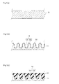
- Figs. 1(a) to 1(c) are schematic cross section views of a method for manufacturing a slide member 10 according to this embodiment.
- the slide member 10 according to this embodiment comprises the substrate 11 in which uneven parts 13 formed by the irradiated laser light and the resin film 12 configured on the substrate 11.
- the method for manufacturing a slide member 10 is explained as below.
- the substrate 11 is provided.
- the substrate 11 may be washed in order to remove impurities such as oils and fats and may be not washed because the laser light is irradiated on the whole surface of the substrate 11 in later steps.
- the material of the substrate 11 in which the laser light is irradiated is not limited especially and metallic material as iron-based material, aluminum-based material, or cupper-based material or complex material in which aluminum, cupper, and so on are fixed and jointed each other may be used as the material.
- the substrate 11 is not limited especially as a flat plate and may be a cylinder or a shape which has special curved surfaces.
- the thickness of the substrate 11 is preferably not less than 0.5 mm. by using the substrate 11 with this thickness, when the laser light is irradiated the substrate 11, the laser light does not pierce and the resin film 12 configured on the substrate 11 is easily configured without spaces.
- the uneven part 13 which is shaped as sine curve is configured.
- the hollow 131 is configured by irradiating the laser light to the substrate 11 constantly and a convexity 132 is configured by providing the unirradiated area which has optimized distance.
- the convexity 132 is configured by separating the laser light by the optimized distance so as to laminate the portion of the substrate 11 of the laser light when the laser light is irradiated. Described as below, the uneven part 13 is configured as the variety shaped uneven part 13 by changing the position of the laser light which is irradiated toward the substrate 11.
- the laser light irradiated to the substrate 11 is explained. Laser machining with the laser light performs the fine machining precisely without contacting the tools and so on to workpieces.
- the laser light irradiated to the substrate 11 may be selected from the YAG laser, semiconductor laser, liquid laser, or gas laser and using YAG laser is preferable in particular in them.
- the melted and solidified portion on the uneven part is configured.
- the portion 14 of the substrate configured on the uneven part 13 means the object by which the substrate 11 is melted, solidified and adhered and the object which is extended from the substrate 11 and solidified without adhering the substrate 11 by irradiating the laser light with optimized energy intensity per unit area to the substrate 11.
- the energy intensity per unit area of laser light is preferably the intensity for configuring the uneven part 13 which has depth described later on the substrate 11 toward a vertical direction and configuring the portion 14 of the substrate 11 on the uneven part 13.
- the energy intensity per unit area of laser light is preferably 0.053 J/mm 2 or more.
- the uneven part 13 is not configured on the substrate 11 and the portion14 of the substrate is not configured on the uneven part 13 of the substrate 11.
- Laser light of the energy intensity per unit area of 0.053 J/mm 2 or more makes the uneven part 13 on the substrate 11 and the portion14 of the substrate on the uneven part 13 of the substrate 11.
- the anchor effect is generated by entering the resin film 12 (described later) to the portion 14 of the substrate and the adhesion between the substrate 11 and the resin film 12 is enhanced.
- the portion 14 of the substrate is shown as beads and the shape of the portion14 of the substrate may be limited to the beads.
- the depth of hollows 131 of the uneven part 13 which is configured by irradiating the laser light with energy intensity per unit area of 0.053 J/mm 2 or more to the whole surface of the substrate 11 are preferably 45 ⁇ m or less toward the vertical direction of the substrate 11. If the depth of the substrate 11 toward the vertical direction is more than 45 ⁇ m, the resin film is not filled up on the whole surface of the uneven part 13 of the substrate 11. The anchor effect to the resin film12 by the portion 14 of the substrate is not generated and the adhesion is decreased.
- the laser light is irradiated constantly so as to overlap about one-fourth of the spot diameter of the laser light when the hollows 131 of the uneven part 13 are configured.
- the hollows 131 of the uneven part 13 and the portion 14 of the substrate which is configured on the uneven part 13 is controlled.
- the convexity 132 of the uneven part 13 is configured that the area unirradiated by laser light is separated from the center of the spot diameter of the laser light by 1 ⁇ m to 80 ⁇ m.
- the area unirradiated by laser light As 1 ⁇ m to 80 ⁇ m, the uneven part 13 which is configured on the substrate 11 and the portion 14 of the substrate which is configured on the substrate 11 is controlled, and the adhesion between the substrate 11 and the resin film 12 is enhanced. Thus, unless the adhesion between the substrate 11 and the resin film 12 is decreased, the area unirradiated by laser light is not provided and the laser light is irradiated in such a way as to overlap the laser light.
- the shape of the uneven part 13 toward the vertical direction configured by irradiating the laser light which has the optimized energy intensity per unit area to the substrate 11 is explained.
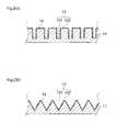
- the Fig. 2(a) and the Fig. 2(b) are the schematic cross section views of the other shape of the uneven part 13 of the substrate 11 in the Fig 1(b) toward the vertical direction.
- the uneven part 13 of the substrate 11 may be configured as the square wave shape.
- the uneven part 13 of the substrate 11 may be configured as the saw tooth wave shape.
- the shapes of the uneven part 13 of the substrate 11 are able to configured as the optimized shape by controlling the laser light which has the optimized energy intensity per unit area, and these shapes are not limited if the resin film is filled up on the whole surface of the substrate 11 when the resin film 12 is configured on the substrate 11 which provides the uneven part 13.
- the portion 14 of the substrate adhered on the uneven part 13 of the substrate 11 by irradiating the laser light with energy intensity per unit area of 0.053 J/mm 2 or more is preferably a heterogeneous shape containing beads, rectangular parallelepipeds, or rhombuses.
- the resin film configured on the substrate 11 is entered to the portion 14 of the substrate configured on the uneven part 13 of this substrate 11 and the anchor effect is generated and the sufficient adhesion is generated under harsh load conditions.
- the size and numbers of the portion 14 of the substrate are controlled by the laser light with energy intensity per unit area of 0.053 J/mm 2 or more.
- the size of the portion 14 of the substrate is 15 ⁇ m or less and the numbers of the portion 14 of the substrate per unit area is 75 units/mm 2 . If they become out of the range, the anchor effect is not generated and the adhesion between the substrate 11 and the resin film 12 is decreased.
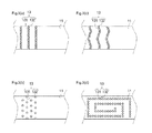
- the Figs. 3(a) to 3(d) are schematic plan views of an uneven part 13 in the Fig 1 (b) .
- the type of the irradiation of the laser light is not limited if the uneven part 13 is configured on the substrate 11.
- the shape of the uneven part 13 may be stripe shape as shown in the Fig. 3(a) , alternate shape as shown in the Fig. 3(b) , or wave shape as shown in the Fig. 3(c) , or spiral shape as shown in the Fig. 3(d) .
- the shape of the uneven part 13 configured by irradiating laser light is not limited if the adhesion to the resin film 13 is kept.
- the resin film 12 is configured on the substrate 11 in which uneven part 13 is configured.
- the resin film 12 is the film including solid lubricant and a binder resin.
- the solid lubricant according to the embodiment of this invention is not limited and for example the solid lubricant is selected from any one of molybdenum disulfide (MoS 2 ), graphite, h - BN, tungsten disulfide (WS 2 ), Pb, or CF and so on. These solid lubricants have the function for lowering and stabilizing the coefficient of friction and for preventing the seizure.
- the average particle size of the solid lubricants is preferably 15 ⁇ m or less and especially preferably from 0,2 ⁇ m to 10 ⁇ m.
- the solid lubricants may be used by mixing one or plural material. These solid lubricants have the function for lowering and stabilizing the coefficient of friction and for preventing the seizure.
- the contents of the solid lubricants contained in the material of the resin film 12 are preferably from 10 % by mass to 80 % by mass and further preferably from 40 % by mass to 60 %. By the contents fallen in these range, the film of the solid lubricants is configured as the film which has the excellent frictional property and wear and abrasion resistance.
- the binder resin is not limited and preferably the resin which has high heat resistance, for example, polyamide imide; polyimide, epoxy resin, phenol resin, polyamide (nylon), fluororesin (PTFE, FEP and so on), or elastomer and so on. These binder resin has the function for keeping the solid lubricants and getting the wear and abrasion resistance.
- the contents of the binder resin contained in the resin film 12 are preferably from 10 % by mass to 80 % by mass. The property for holding the solid lubricants and the wear and abrasion resistance are obtained by the contents fallen in these range,
- the material of the resin film 12 may include addition agent other than the above.
- the addition agent is solid particle as Al 2 O 3 , Si 2 N 4 , TiO 2 or SiO 2 and so on or extreme pressure agent.
- the method for configuring the resin film 12 on the surface of the substrate 11 is not limited.
- the resin film may be configured by drying and firing by 150 degrees Celsius or more and 300 degrees Celsius or less.
- a tumbling method, a dipping method, a brush painting method, or roll shaped method and so on is used other than the spray soaking method (for example air spray or air electrostatic coating).
- the thickness of the resin film 12 is 1 ⁇ m or more and 50 ⁇ m or less.
- the resin film 12 configured on the substrate may provide some holes which is the oil sump opened at the sliding surface.
- the shape of the open face of the hole is not limited and may be shaped as circle shape, elliptical shape, or polygon shape.
- This hole may be configured by YAG laser described above.
- the depth of the hole is preferably 5 ⁇ m or more and 40 ⁇ m or less. The spillage of lubricating oil and so on is prevented and the lubricating oil and foreign bodies by the depth in this range.
- the depth of this hole is preferably less than the thickness of the resin film 12. It is not necessary that the hole is configured at the whole sliding surface and the specific position where the load is added on sliding.
- a convexity may be shaped adjacent to the grooves so as to increase the initial conformability and to obtain the excellent sliding property under harsh load conditions.
- a convexity may be shaped adjacent to the grooves and the cross - sectional shape of the groove is not limited if the lubricating oil is kept.
- the cross - sectional shape of the groove is for example semi-circle shape, triangle shape, or trapezoid shape and so on.
- the cross - sectional shape of the groove is preferably semi-circle shape or triangle shape because the formation rates of the convexity is high and the initial contact pressure is high and the deformation and the wear are caused easily and the initial conformability is achieved satisfactorily.
- the cross - sectional shape of the groove is preferably semi-circle shape to keep much lubricating oil.
- the depth and the pitch of the circumferential groove is not limited and suitably set by the shape, size and the necessary sliding property.
- the depth of the circumferential groove is usually 1 ⁇ m - 20 ⁇ m and preferably 1 ⁇ m - 7 ⁇ m.
- the pitch of the circumferential groove is usually 0.05 ⁇ m - 1 mm and preferably 0.1 ⁇ m - 0.5mm.
- the depth and the pitch of the circumferential groove may be changed randomly on the sliding surface according to the peripheral speed difference and the sliding property and so on.
- FIG.5 is the schematic cross section view of the compressor 40 using sliding member 10 as the swash plate according to the practical example of the invention. As shown in the Fig.
- the compressor 40 using sliding member 10 as the swash plate provides the swash plate 17 as the sliding member 10 provided at the outer circumference of the axle slantingly, the cut-out portion at the edge to cover the outer circumference of the swash plate 17 and to be disposed along the axle, piston 20 which has the couple of the semi-circle hollow configured in the cut-out portion at the edge, and the couple of the semi-circle shoe 30, 31 disposed at the couple of the semi-circle hollow of the piston 20.
- the sliding member 10 is able to prevent the resin film 12 from peeling from the substrate in spite of under the harsh load conditions, for example, under the poor lubricity or under the no lubricity in case that lubrication oil adhered on the sliding member 10 is flew out by flowing gas.
- the lubrication oil is not supplied to the surface in the initial stage of the drive, the lubrication oil which is kept in the hole as an oil sump is oozed and the occasion of contact between solids are decreased and the seize resistance is increased.
- the adhesion between the substrate 11 and resin film 12 is sufficiently kept and the initial conformability and the wear and abrasion resistance is achieved.
- the sliding member 10 is used as the swash plate 17 for the compressor 40 explained above.
- the above laser light is used when the substrate 11 is not only metallic material as iron-based material, aluminum-based material, or cupper-based material but the material which is necessary to increase the adhesion.
- the sliding member 10 is used for the piston or the shoe 30, 31.
- the laser light with energy intensity per unit area of 0.05 J/mm 2 is irradiated constantly and the hollows 131 of depth of 2 ⁇ m are configured toward the vertical direction of the substrate 11.
- the distance from the center of the spot of the laser light to the corner of the convexity 132 unirradiated by laser light is 60 ⁇ m.
- the area unirradiated by laser light is configured focusing on the corner of the convexity 132 and the uneven part 13 is configured on the substrate 11 and the portion 14 of the substrate is configured on the uneven part 13.
- the laser light irradiated to the substrate 11 according to example is YAG laser light.
- the uneven part 13 configured on the substrate 11 and the portion 14 of the substrate configured on the uneven part 13 are explained.
- the Fig. 5(a) is the schematic view of surface of the portion 14 of a substrate configured on a uneven part 13 of the substrate 11 according to the example 1
- the Fig. 5(b) is the schematic view of surface of portion 14 of a substrate configured on a uneven part 13 of the substrate 11 according to the example 1. As shown in the Fig. 5(a) and the Fig.
- the portion 14 of a substrate configured on a uneven part 13 of the substrate 11 is adhered on the hollows 131 of the substrate 11 by irradiating the laser light with energy intensity per unit area of 0.05 J/mm 2 and the objects like the splash on the hollows 131 of the substrate 11 are solidified.
- the portion 14 of a substrate of 75 units/mm 2 is configured. This result is shown in the Table 1.
- the resin film 12 is configured on the substrate 11 on which configure the uneven part 13.
- the material is provided as the resin film 12 contains 25% by mass molybdenum disulfide, 30% by mass graphite, and remains polyamide imide.
- the N-methyl-2-pyrrolidone as the solvent of the resin is added to the material and by the roll printing method the resin film of thickness of 60 ⁇ m is configured by adhering the resin on the substrate 11 of the uneven part 13 contained the portion 14 of the substrate.
- sliding member 10 according to the example 1 is configured.
- the slide member 10 according to this example 2 is configured by the same method as the example 1 except that the laser light with energy intensity per unit area of 0.10 J/mm 2 is irradiated.
- the depth of the uneven part 13 toward the vertical direction is 5 ⁇ m and the portion 14 of the substrate per unit area is 100 units/mm 2 is configured. This result is shown in the Table 1.
- the slide member 10 according to this example 3 is configured by the same method as the example 1 except that the laser light with energy intensity per unit area of 0.24 J/mm 2 is irradiated.
- the depth of the uneven part 13 toward the vertical direction is 10 ⁇ m and the portion 14 of the substrate per unit area is 7000 units/mm 2 is configured. This result is shown in the Table 1.
- the slide member 10 according to this example 4 is configured by the same method as the example 1 except that the laser light with energy intensity per unit area of 0.34 J/mm 2 is irradiated.
- the depth of the uneven part 13 toward the vertical direction is 15 ⁇ m and the portion 14 of the substrate per unit area is 8000 units/mm 2 is configured. This result is shown in the Table 1.
- the slide member 10 is configured by the same method as the example 1 except that the laser light with energy intensity per unit area of 0.04 J/mm 2 is irradiated.
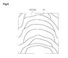
- the Fig. 6 is the schematic view of surface of the portion 14 of a substrate configured on a uneven part 13 of the substrate 11 according to the comparative example 1. As shown in the Fig. 6 , in the portion 14 of a substrate on a uneven part 13 of the substrate 11, the objects like the splash on the hollows 131 of the substrate 11 are solidified by irradiating the laser light with energy intensity per unit area of 0.04 J/mm 2 . In the sliding member 10, the depth of the uneven part 13 toward the vertical direction is 1 ⁇ m and the portion 14 of the substrate per unit area is 0 units/mm 2 is configured.
- the portion 14 of a substrate is configured on the uneven part 13 of the substrate 11 by controlling the laser light with energy intensity per unit area.
- the adhesion is enhanced and the initial conformability is enhanced and the excellent frictional property and excellent wear and abrasion resistance are achieved.
- the adhesion is not achieved and the peeling of the resin film is generated.
- the present invention is acceptable to the skill of a sliding member, a method for manufacturing sliding member, and a compressor swash plate using sliding member.
Landscapes
- Chemical & Material Sciences (AREA)
- Engineering & Computer Science (AREA)
- Organic Chemistry (AREA)
- Chemical Kinetics & Catalysis (AREA)
- General Engineering & Computer Science (AREA)
- Mechanical Engineering (AREA)
- General Chemical & Material Sciences (AREA)
- Oil, Petroleum & Natural Gas (AREA)
- Health & Medical Sciences (AREA)
- Medicinal Chemistry (AREA)
- Polymers & Plastics (AREA)
- Life Sciences & Earth Sciences (AREA)
- Wood Science & Technology (AREA)
- Materials Engineering (AREA)
- Manufacturing & Machinery (AREA)
- Metallurgy (AREA)
- Compressors, Vaccum Pumps And Other Relevant Systems (AREA)
- Compressor (AREA)
- Laminated Bodies (AREA)
- Application Of Or Painting With Fluid Materials (AREA)
- Physics & Mathematics (AREA)
- Plasma & Fusion (AREA)
- Laser Beam Processing (AREA)
Abstract
Description
- The present invention relates to a sliding member, a method for manufacturing sliding member, and a compressor swash plate using sliding member.
- In a conventional sliding member, surfaces of a substrate are roughened by shot-blasting of aluminum, iron or cupper or by irradiating laser light to the substrate and resin is configured on the roughened substrate.
- However, in a conventional sliding member, although a surface of a substrate is roughened by shot-blasting or irradiating laser light and resin is configured on the roughened substrate, the adhesion between the roughened substrate and the resin configured on the substrate is able to be not enough and the resin is peeled from the resin.
- As the method for preventing the resin from peeling by irradiating laser light to the substrate and roughening the surface of the substrate, for example, it is described in the Patent Literature 1. In the method described in the Patent Literature 1 for preventing the resin from peeling by irradiating laser light to a base material and roughening the surface of the base material, the percentage of the irradiation of the laser light which irradiates the surface of the base material is not less than 44 %, the surface of the base material is roughened, the resin is coated at the roughened surface of the base material, and peeling of the resin does not occur.
- Patent Literature 1: the Japanese Patent Publication No.
2007-289963 - In the conventional method for roughening the base material by irradiating the laser to the surface of the base material, a hollow toward the vertical direction of the base material is able to be not enough, because the anchor effect between the base material and the resin coated at the base material is not achieved, the coated resin is able to be peeled from the base material, the adhesion between the base material and the resin is able to be not enough, and the durability to the adhesion between the base material and the resin is able to be not enough under harsh load conditions.
- In consideration of the above problems, the present invention provides the sliding member, method for manufacturing the sliding member, and compressor swash plate using sliding member in which adhesion between the substrate and the resin is enhanced, and which has the excellent durability whereby peeling of the resin film from the substrate does not occur due to prolonged sliding even under harsh load conditions by irradiating the laser light in which the energy intensity per unit area is optimized to the substrate and by setting the hollow toward the vertical direction as the optimized depth for not peeling the resin film configured at the substrate.
- The sliding member according to an embodiment of this invention is characterized by providing a substrate irradiated laser light with energy intensity per unit area of 0.053 J/mm2 or more and configured an uneven part formed toward a vertical direction by the irradiated laser light and a melted and solidified portion on the uneven part and a resin film including solid lubricant and a binder resin on the substrate.
- The method for manufacturing slide member according to an embodiment of this invention is characterized by irradiating laser light with energy intensity per unit area of 0.053 J/mm2 or more and configuring an uneven part formed toward a vertical direction on a substrate, configuring a melted and solidified portion on the uneven part of the substrate, and configuring a resin film including solid lubricant and a binder resin on the substrate.
- By irradiating laser light with optimized energy intensity per unit area to the substrate and by setting the hollow toward the vertical direction as the optimized depth for not peeling the resin film configured at the substrate, the present invention can provide the sliding member, method for manufacturing the sliding member, and compressor swash plate using sliding member in which adhesion between the substrate and the resin is enhanced, and which has the excellent durability whereby peeling of the resin film from the substrate does not occur due to prolonged sliding even under harsh load conditions.
-
- [
Fig. 1] Fig. 1(a) to Fig. 1(c) are schematic cross section views of a method for manufacturing a slide member according to this embodiment. - [
Fig. 2] Fig. 2(a) and Fig 2(b) are schematic cross section views of a shape of a substrate in theFig 1(b) toward the vertical direction. - [
Fig. 3] Fig. 3(a) to Fig. 3(d) are schematic plan views of an uneven shape of a substrate in theFig 1(b) . - [
Fig. 4] Fig. 4 is a schematic cross section view of a compressor swash plate using sliding member according to this embodiment. - [
Fig. 5] Fig. 5(a) is a schematic cross section view of a compressor swash plate using sliding member according to the practical example 1 of the invention. - [
Fig. 6] Fig. 6 is a schematic view of surface of portion of a substrate configured on a uneven part of the substrate according to the compared example 1. - An embodiment of the invention is explained in detail with referring the drawings as below. Thus, this invention is not limited to the below embodiment.
- The
Figs. 1(a) to 1(c) are schematic cross section views of a method for manufacturing a slide member 10 according to this embodiment. As shown in theFig. 1(c) , the slide member 10 according to this embodiment comprises thesubstrate 11 in whichuneven parts 13 formed by the irradiated laser light and theresin film 12 configured on thesubstrate 11. - The method for manufacturing a slide member 10 according to this embodiment is explained as below. As shown in the
Fig. 1(a) , firstly thesubstrate 11 is provided. Thesubstrate 11 may be washed in order to remove impurities such as oils and fats and may be not washed because the laser light is irradiated on the whole surface of thesubstrate 11 in later steps. The material of thesubstrate 11 in which the laser light is irradiated is not limited especially and metallic material as iron-based material, aluminum-based material, or cupper-based material or complex material in which aluminum, cupper, and so on are fixed and jointed each other may be used as the material. Thesubstrate 11 is not limited especially as a flat plate and may be a cylinder or a shape which has special curved surfaces. The thickness of thesubstrate 11 is preferably not less than 0.5 mm. by using thesubstrate 11 with this thickness, when the laser light is irradiated thesubstrate 11, the laser light does not pierce and theresin film 12 configured on thesubstrate 11 is easily configured without spaces. - Next, as shown in the
Fig. 1(b) , by irradiating the laser light which has the optimized energy intensity per unit area to thesubstrate 11, for example, theuneven part 13 which is shaped as sine curve is configured. In theuneven part 13 which is shaped as sine curve, the hollow 131 is configured by irradiating the laser light to thesubstrate 11 constantly and aconvexity 132 is configured by providing the unirradiated area which has optimized distance. Theconvexity 132 is configured by separating the laser light by the optimized distance so as to laminate the portion of thesubstrate 11 of the laser light when the laser light is irradiated. Described as below, theuneven part 13 is configured as the variety shapeduneven part 13 by changing the position of the laser light which is irradiated toward thesubstrate 11. - The laser light irradiated to the
substrate 11 is explained. Laser machining with the laser light performs the fine machining precisely without contacting the tools and so on to workpieces. For example, the laser light irradiated to thesubstrate 11 may be selected from the YAG laser, semiconductor laser, liquid laser, or gas laser and using YAG laser is preferable in particular in them. - In the
uneven part 13 of thesubstrate 11 according to the embodiment of this invention, by irradiating the laser light with optimized energy intensity per unit area to thesubstrate 11, the melted and solidified portion on the uneven part is configured. Theportion 14 of the substrate configured on theuneven part 13 means the object by which thesubstrate 11 is melted, solidified and adhered and the object which is extended from thesubstrate 11 and solidified without adhering thesubstrate 11 by irradiating the laser light with optimized energy intensity per unit area to thesubstrate 11. The energy intensity per unit area of laser light is preferably the intensity for configuring theuneven part 13 which has depth described later on thesubstrate 11 toward a vertical direction and configuring theportion 14 of thesubstrate 11 on theuneven part 13. The energy intensity per unit area of laser light is preferably 0.053 J/mm2 or more. If the energy intensity per unit area of laser light is less than 0.053 J/mm2, theuneven part 13 is not configured on thesubstrate 11 and the portion14 of the substrate is not configured on theuneven part 13 of thesubstrate 11. Laser light of the energy intensity per unit area of 0.053 J/mm2 or more makes theuneven part 13 on thesubstrate 11 and the portion14 of the substrate on theuneven part 13 of the substrate 11.The anchor effect is generated by entering the resin film 12 (described later) to theportion 14 of the substrate and the adhesion between thesubstrate 11 and theresin film 12 is enhanced. Thus, In theFig.1 to theFig. 3 , theportion 14 of the substrate is shown as beads and the shape of the portion14 of the substrate may be limited to the beads. - The depth of
hollows 131 of theuneven part 13 which is configured by irradiating the laser light with energy intensity per unit area of 0.053 J/mm2 or more to the whole surface of thesubstrate 11 are preferably 45 µm or less toward the vertical direction of thesubstrate 11. If the depth of thesubstrate 11 toward the vertical direction is more than 45µm, the resin film is not filled up on the whole surface of theuneven part 13 of thesubstrate 11. The anchor effect to the resin film12 by theportion 14 of the substrate is not generated and the adhesion is decreased. - The laser light is irradiated constantly so as to overlap about one-fourth of the spot diameter of the laser light when the
hollows 131 of theuneven part 13 are configured. By irradiating the laser light so as to overlap the spot diameter of the laser light, thehollows 131 of theuneven part 13 and theportion 14 of the substrate which is configured on theuneven part 13 is controlled. For example, theconvexity 132 of theuneven part 13 is configured that the area unirradiated by laser light is separated from the center of the spot diameter of the laser light by 1µm to 80µm. By setting the area unirradiated by laser light as 1µm to 80µm, theuneven part 13 which is configured on thesubstrate 11 and theportion 14 of the substrate which is configured on thesubstrate 11 is controlled, and the adhesion between thesubstrate 11 and theresin film 12 is enhanced. Thus, unless the adhesion between thesubstrate 11 and theresin film 12 is decreased, the area unirradiated by laser light is not provided and the laser light is irradiated in such a way as to overlap the laser light. - The shape of the
uneven part 13 toward the vertical direction configured by irradiating the laser light which has the optimized energy intensity per unit area to thesubstrate 11 is explained. TheFig. 2(a) and theFig. 2(b) are the schematic cross section views of the other shape of theuneven part 13 of thesubstrate 11 in theFig 1(b) toward the vertical direction. As shown in theFig. 2(a) , theuneven part 13 of thesubstrate 11 may be configured as the square wave shape. As shown in theFig. 2(b) , theuneven part 13 of thesubstrate 11 may be configured as the saw tooth wave shape. The shapes of theuneven part 13 of thesubstrate 11 are able to configured as the optimized shape by controlling the laser light which has the optimized energy intensity per unit area, and these shapes are not limited if the resin film is filled up on the whole surface of thesubstrate 11 when theresin film 12 is configured on thesubstrate 11 which provides theuneven part 13. - The
portion 14 of the substrate adhered on theuneven part 13 of thesubstrate 11 by irradiating the laser light with energy intensity per unit area of 0.053 J/mm2 or more is preferably a heterogeneous shape containing beads, rectangular parallelepipeds, or rhombuses. By theportion 14 of the substrate which provides the heterogeneous shape containing beads, rectangular parallelepipeds, or rhombuses, the resin film configured on thesubstrate 11 is entered to theportion 14 of the substrate configured on theuneven part 13 of thissubstrate 11 and the anchor effect is generated and the sufficient adhesion is generated under harsh load conditions. About theportion 14 of the substrate configured on theuneven part 13 of thissubstrate 11, the size and numbers of theportion 14 of the substrate are controlled by the laser light with energy intensity per unit area of 0.053 J/mm2 or more. The size of theportion 14 of the substrate is 15µm or less and the numbers of theportion 14 of the substrate per unit area is 75 units/mm2. If they become out of the range, the anchor effect is not generated and the adhesion between thesubstrate 11 and theresin film 12 is decreased. - The
Figs. 3(a) to 3(d) are schematic plan views of anuneven part 13 in theFig 1 (b) . As shown in theFigs. 3(a) to 3(d) , the type of the irradiation of the laser light is not limited if theuneven part 13 is configured on thesubstrate 11. The shape of theuneven part 13 may be stripe shape as shown in theFig. 3(a) , alternate shape as shown in theFig. 3(b) , or wave shape as shown in theFig. 3(c) , or spiral shape as shown in theFig. 3(d) . The shape of theuneven part 13 configured by irradiating laser light is not limited if the adhesion to theresin film 13 is kept. - Next, as shown in the
Fig. 1(c) , theresin film 12 is configured on thesubstrate 11 in whichuneven part 13 is configured. Theresin film 12 is the film including solid lubricant and a binder resin. The solid lubricant according to the embodiment of this invention is not limited and for example the solid lubricant is selected from any one of molybdenum disulfide (MoS2), graphite, h - BN, tungsten disulfide (WS2), Pb, or CF and so on. These solid lubricants have the function for lowering and stabilizing the coefficient of friction and for preventing the seizure. For achieving the sufficient effect of the function, the average particle size of the solid lubricants is preferably 15µm or less and especially preferably from 0,2µm to 10µm. - The solid lubricants may be used by mixing one or plural material. These solid lubricants have the function for lowering and stabilizing the coefficient of friction and for preventing the seizure. The contents of the solid lubricants contained in the material of the
resin film 12 are preferably from 10 % by mass to 80 % by mass and further preferably from 40 % by mass to 60 %. By the contents fallen in these range, the film of the solid lubricants is configured as the film which has the excellent frictional property and wear and abrasion resistance. - The binder resin is not limited and preferably the resin which has high heat resistance, for example, polyamide imide; polyimide, epoxy resin, phenol resin, polyamide (nylon), fluororesin (PTFE, FEP and so on), or elastomer and so on. These binder resin has the function for keeping the solid lubricants and getting the wear and abrasion resistance. The contents of the binder resin contained in the
resin film 12 are preferably from 10 % by mass to 80 % by mass. The property for holding the solid lubricants and the wear and abrasion resistance are obtained by the contents fallen in these range, - The material of the
resin film 12 may include addition agent other than the above. For example, the addition agent is solid particle as Al2O3, Si2N4, TiO2 or SiO2 and so on or extreme pressure agent. - The method for configuring the
resin film 12 on the surface of thesubstrate 11 is not limited. For example, after the material of theresin film 12 is mixed to the surface of thesubstrate 11 including theuneven part 13 and soaked by spray, the resin film may be configured by drying and firing by 150 degrees Celsius or more and 300 degrees Celsius or less. A tumbling method, a dipping method, a brush painting method, or roll shaped method and so on is used other than the spray soaking method (for example air spray or air electrostatic coating). The thickness of theresin film 12 is 1µm or more and 50µm or less. - The
resin film 12 configured on the substrate may provide some holes which is the oil sump opened at the sliding surface. The shape of the open face of the hole is not limited and may be shaped as circle shape, elliptical shape, or polygon shape. This hole may be configured by YAG laser described above. The depth of the hole is preferably 5µm or more and 40µm or less. The spillage of lubricating oil and so on is prevented and the lubricating oil and foreign bodies by the depth in this range. The depth of this hole is preferably less than the thickness of theresin film 12. It is not necessary that the hole is configured at the whole sliding surface and the specific position where the load is added on sliding. - In the
resin film 12 configured on thesubstrate 11, a convexity may be shaped adjacent to the grooves so as to increase the initial conformability and to obtain the excellent sliding property under harsh load conditions. In this case, a convexity may be shaped adjacent to the grooves and the cross - sectional shape of the groove is not limited if the lubricating oil is kept. The cross - sectional shape of the groove is for example semi-circle shape, triangle shape, or trapezoid shape and so on. The cross - sectional shape of the groove is preferably semi-circle shape or triangle shape because the formation rates of the convexity is high and the initial contact pressure is high and the deformation and the wear are caused easily and the initial conformability is achieved satisfactorily. Especially, the cross - sectional shape of the groove is preferably semi-circle shape to keep much lubricating oil. - The depth and the pitch of the circumferential groove is not limited and suitably set by the shape, size and the necessary sliding property. The depth of the circumferential groove is usually 1µm - 20µm and preferably 1µm - 7µm. The pitch of the circumferential groove is usually 0.05µm - 1 mm and preferably 0.1µm - 0.5mm. In the sliding surface, it is not necessary that the depth and the pitch of the all circumferential grooves are same length, the depth and the pitch of the circumferential groove may be changed randomly on the sliding surface according to the peripheral speed difference and the sliding property and so on.
- Next, the example with the sliding member 10 according to the embodiment of this invention as the
swash plate 17 for thecompressor 40. TheFig.5 is the schematic cross section view of thecompressor 40 using sliding member 10 as the swash plate according to the practical example of the invention. As shown in theFig. 5 , thecompressor 40 using sliding member 10 as the swash plate provides theswash plate 17 as the sliding member 10 provided at the outer circumference of the axle slantingly, the cut-out portion at the edge to cover the outer circumference of theswash plate 17 and to be disposed along the axle,piston 20 which has the couple of the semi-circle hollow configured in the cut-out portion at the edge, and the couple of thesemi-circle shoe piston 20. - The sliding member 10 according to the embodiment of this invention is able to prevent the
resin film 12 from peeling from the substrate in spite of under the harsh load conditions, for example, under the poor lubricity or under the no lubricity in case that lubrication oil adhered on the sliding member 10 is flew out by flowing gas. When the lubrication oil is not supplied to the surface in the initial stage of the drive, the lubrication oil which is kept in the hole as an oil sump is oozed and the occasion of contact between solids are decreased and the seize resistance is increased. - According to the sliding member 10 according to the embodiment of this invention, the adhesion between the
substrate 11 andresin film 12 is sufficiently kept and the initial conformability and the wear and abrasion resistance is achieved. - The sliding member 10 according to the embodiment of this invention is used as the
swash plate 17 for thecompressor 40 explained above. The above laser light is used when thesubstrate 11 is not only metallic material as iron-based material, aluminum-based material, or cupper-based material but the material which is necessary to increase the adhesion. For example, the sliding member 10 is used for the piston or theshoe - The example of this invention is explained in detail. Firstly, referring to the
Figs. 1(a) to 1(c) , the sliding member 10 according to the example of this invention is explained, and the compressor swash plate using the sliding member 10 is explained. - The slide member 10 according to this example 1, as shown in the
Fig. 1(a) , the iron-basedsubstrate 11 which has the 6mm thickness is provided, polished and cleaned for removing the impurities such as oils and fats. - Next, as shown in the
Fig. 1 (b) , the laser light with energy intensity per unit area of 0.05 J/mm2 is irradiated constantly and thehollows 131 of depth of 2 µm are configured toward the vertical direction of thesubstrate 11. The distance from the center of the spot of the laser light to the corner of theconvexity 132 unirradiated by laser light is 60 µm. The area unirradiated by laser light is configured focusing on the corner of theconvexity 132 and theuneven part 13 is configured on thesubstrate 11 and theportion 14 of the substrate is configured on theuneven part 13. The laser light irradiated to thesubstrate 11 according to example is YAG laser light. - The
uneven part 13 configured on thesubstrate 11 and theportion 14 of the substrate configured on theuneven part 13 are explained. TheFig. 5(a) is the schematic view of surface of theportion 14 of a substrate configured on auneven part 13 of thesubstrate 11 according to the example 1 and theFig. 5(b) is the schematic view of surface ofportion 14 of a substrate configured on auneven part 13 of thesubstrate 11 according to the example 1. As shown in theFig. 5(a) and theFig. 5(b) , theportion 14 of a substrate configured on auneven part 13 of thesubstrate 11 is adhered on thehollows 131 of thesubstrate 11 by irradiating the laser light with energy intensity per unit area of 0.05 J/mm2 and the objects like the splash on thehollows 131 of thesubstrate 11 are solidified. Thus, theportion 14 of a substrate of 75 units/mm2 is configured. This result is shown in the Table 1. - Nest, as shown in the
Fig. 1(c) , theresin film 12 is configured on thesubstrate 11 on which configure theuneven part 13. The material is provided as theresin film 12 contains 25% by mass molybdenum disulfide, 30% by mass graphite, and remains polyamide imide. The N-methyl-2-pyrrolidone as the solvent of the resin is added to the material and by the roll printing method the resin film of thickness of 60µm is configured by adhering the resin on thesubstrate 11 of theuneven part 13 contained theportion 14 of the substrate. Later, the firing by 220 degrees Celsius at a holding time of 1 hour is performed and next the cutting by using lathe which has the diamonds tip of the nose radius of 0.8 is performed by the feeding speed of the 0.16 mm and the circumferential groove of the pitch of 0.16 mm and the depth of 4µm is configured. By the method, sliding member 10 according to the example 1 is configured. - The slide member 10 according to this example 2 is configured by the same method as the example 1 except that the laser light with energy intensity per unit area of 0.10 J/mm2 is irradiated. In the sliding member, the depth of the
uneven part 13 toward the vertical direction is 5µm and theportion 14 of the substrate per unit area is 100 units/mm2 is configured. This result is shown in the Table 1. - The slide member 10 according to this example 3 is configured by the same method as the example 1 except that the laser light with energy intensity per unit area of 0.24 J/mm2 is irradiated. In the sliding member, the depth of the
uneven part 13 toward the vertical direction is 10µm and theportion 14 of the substrate per unit area is 7000 units/mm2 is configured. This result is shown in the Table 1. - The slide member 10 according to this example 4 is configured by the same method as the example 1 except that the laser light with energy intensity per unit area of 0.34 J/mm2 is irradiated. In the sliding member, the depth of the
uneven part 13 toward the vertical direction is 15µm and theportion 14 of the substrate per unit area is 8000 units/mm2 is configured. This result is shown in the Table 1. - The slide member 10 is configured by the same method as the example 1 except that the laser light with energy intensity per unit area of 0.04 J/mm2 is irradiated. The
Fig. 6 is the schematic view of surface of theportion 14 of a substrate configured on auneven part 13 of thesubstrate 11 according to the comparative example 1. As shown in theFig. 6 , in theportion 14 of a substrate on auneven part 13 of thesubstrate 11, the objects like the splash on thehollows 131 of thesubstrate 11 are solidified by irradiating the laser light with energy intensity per unit area of 0.04 J/mm2. In the sliding member 10, the depth of theuneven part 13 toward the vertical direction is 1µm and theportion 14 of the substrate per unit area is 0 units/mm2 is configured. This result is shown in the Table 1.[Table 1] The energy intensity per unit area (J/mm2) The depth of a concave portion (µm) The number of parts of material per unit area (/mm2) operation 1 0.05 2 75 operation 2 0.10 5 100 operation 3 0.24 10 7000 operation 4 0.34 15 8000 example 1 0.04 1 0 - Under the below condition, the peeling test and the abrasion test in which the slide member 10 according to embodiments 1 to 4 and the comparative example 1 are used as the compressor swash plate is performed. This result is shown in the Table 2.
Test form: 3 shoes / flat plate
Engine speed: 7200 rpm
Load: 1735 N
Lubrication: refrigerant/coolant oil mixed, atmosphere inducted by compressor
Opposite material: shoe (firing SUJ2)[Table 2] The seizure Load [N] The coefficient of friction The abrasion wear [µm] Remarks operation 1 1735 or more than 1735 0.007 3 µm No avulsion of resin layer operation 2 1735 or more than 1735 0.006 1 µm No avulsion of resin laser operation 3 1735 or more than 1735 0.005 2 µm No avulsion of resin laser operation 4 1735 or more than 1735 0.006 2 µm No avulsion of resin layer example 1 1183 0.012 20(avulsion part) Avulsion of resin laver - As shown in the Table 2, According to this embodiment 1 to this embodiment 4, the
portion 14 of a substrate is configured on theuneven part 13 of thesubstrate 11 by controlling the laser light with energy intensity per unit area. The adhesion is enhanced and the initial conformability is enhanced and the excellent frictional property and excellent wear and abrasion resistance are achieved. In the other hand, the adhesion is not achieved and the peeling of the resin film is generated. - The present invention is acceptable to the skill of a sliding member, a method for manufacturing sliding member, and a compressor swash plate using sliding member.
-
- 10
- sliding member
- 11
- substrate
- 12
- resin film
- 13
- uneven part
- 14
- portion of the substrate
Claims (9)
- A slide member comprising,
a substrate irradiated laser light with energy intensity per unit area of 0.053 J/mm2 or more and configured an uneven part formed toward a vertical direction by the irradiated laser light and a melted and solidified portion on the uneven part, and
a resin film including solid lubricant and a binder resin on the substrate. - The slide member according to claim 1,
wherein the uneven part has hollows of depth of 45 µm or less toward the vertical direction of the substrate. - The slide member according to claim 1 or 2,
wherein the portion of the substrate is a heterogeneous shape containing beads, rectangular parallelepipeds, or rhombuses. - The slide member according to any one of claims 1 to 3,
wherein the solid lubricant is selected from any one of molybdenum disulfide (MoS2), graphite, h - BN, tungsten disulfide (WS2), Pb, or CF. - A compressor swash plate using the slide member according to any one of claims 1 to 4.
- A method for manufacturing a slide member comprising the step of,
irradiating laser light with energy intensity per unit area of 0.053 J/mm2 or more and configuring an uneven part formed toward a vertical direction on a substrate,
configuring a melted and solidified portion on the uneven part of the substrate, and configuring a resin film including solid lubricant and a binder resin on the substrate. - The method for manufacturing the slide member according to claim 6,
wherein the uneven part has hollows of depth of 45 µm or less toward the vertical direction of the substrate. - The method for manufacturing the slide member according to claim 6 or 7,
wherein the portion of the substrate is a heterogeneous shape containing beads, rectangular parallelepipeds, or rhombuses. - The method for manufacturing the slide member according to any one of claims 6 to 8,
wherein the solid lubricant is selected from any one of molybdenum disulfide(MoS2), graphite, h - BN, tungsten disulfide(WS2), Pb, or CF.
Applications Claiming Priority (2)
| Application Number | Priority Date | Filing Date | Title |
|---|---|---|---|
| JP2013021779A JP5903391B2 (en) | 2013-02-06 | 2013-02-06 | Manufacturing method of sliding member |
| PCT/JP2014/052686 WO2014123159A1 (en) | 2013-02-06 | 2014-02-05 | Sliding member, method for manufacturing same, and compressor swash plate using sliding member |
Publications (3)
| Publication Number | Publication Date |
|---|---|
| EP2955023A1 true EP2955023A1 (en) | 2015-12-16 |
| EP2955023A4 EP2955023A4 (en) | 2016-11-09 |
| EP2955023B1 EP2955023B1 (en) | 2019-10-02 |
Family
ID=51299751
Family Applications (1)
| Application Number | Title | Priority Date | Filing Date |
|---|---|---|---|
| EP14749634.3A Active EP2955023B1 (en) | 2013-02-06 | 2014-02-05 | Sliding member, method for manufacturing sliding member, and compressor swash plate using sliding member |
Country Status (6)
| Country | Link |
|---|---|
| US (1) | US10260491B2 (en) |
| EP (1) | EP2955023B1 (en) |
| JP (1) | JP5903391B2 (en) |
| KR (1) | KR101946684B1 (en) |
| CN (1) | CN105142903B (en) |
| WO (1) | WO2014123159A1 (en) |
Families Citing this family (11)
| Publication number | Priority date | Publication date | Assignee | Title |
|---|---|---|---|---|
| JP6571960B2 (en) * | 2015-03-24 | 2019-09-04 | Ntn株式会社 | Swash plate compressor hemispherical shoe and swash plate compressor |
| JP6688113B2 (en) * | 2016-03-18 | 2020-04-28 | 大豊工業株式会社 | Surface processing method for sliding bearing and sliding bearing |
| JP6723855B2 (en) * | 2016-07-22 | 2020-07-15 | キヤノンマシナリー株式会社 | Sliding surface structure |
| DE112017004869T5 (en) * | 2016-09-28 | 2019-07-04 | Ntn Corporation | slide |
| JP6928454B2 (en) * | 2017-02-01 | 2021-09-01 | 大豊工業株式会社 | Manufacturing method of sliding member, sliding member, swash plate for compressor using sliding member |
| CN107101084B (en) * | 2017-06-14 | 2018-11-06 | 合肥工业大学 | The method that the reaction of fricting shearing induced chemical reduces friction coefficient in surface filming |
| JP2019082148A (en) | 2017-10-31 | 2019-05-30 | 大豊工業株式会社 | Swash plate |
| JP6777063B2 (en) * | 2017-12-20 | 2020-10-28 | 株式会社デンソー | Electronic devices and their manufacturing methods |
| AT521246B1 (en) * | 2018-07-10 | 2019-12-15 | Miba Gleitlager Austria Gmbh | plain bearing element |
| WO2020075561A1 (en) * | 2018-10-12 | 2020-04-16 | 大日本印刷株式会社 | Decorative sheet, transparent resin film, and decorative sheet production method |
| KR102829658B1 (en) | 2019-04-18 | 2025-07-03 | 다이니폰 인사츠 가부시키가이샤 | Transparent resin film, method for producing transparent resin film, and cosmetic material |
Family Cites Families (12)
| Publication number | Priority date | Publication date | Assignee | Title |
|---|---|---|---|---|
| JPS601384A (en) * | 1983-06-17 | 1985-01-07 | Taiho Kogyo Co Ltd | Swash plate type compressor |
| JPH0483914A (en) * | 1990-07-24 | 1992-03-17 | Taiho Kogyo Co Ltd | plain bearing material |
| JPH1058595A (en) * | 1996-08-15 | 1998-03-03 | Nikken Toso Kogyo Kk | Method for forming fluororesin coat |
| JPH11106779A (en) * | 1997-10-03 | 1999-04-20 | Taiho Kogyo Co Ltd | Solid lubricating coating composition and sliding bearing material using the same |
| JP2003211084A (en) | 2001-10-26 | 2003-07-29 | Seiko Instruments Inc | Method for applying fluorocarbon resin, sliding member using the method and gas compressor |
| JP4846669B2 (en) | 2001-10-26 | 2011-12-28 | カルソニックカンセイ株式会社 | Fluorine resin coating method, sliding member using the method, and gas compressor |
| JP3931990B2 (en) * | 2005-04-27 | 2007-06-20 | 大豊工業株式会社 | Sliding device |
| JP4569829B2 (en) * | 2006-01-23 | 2010-10-27 | 株式会社豊田自動織機 | Sliding member |
| JP5184320B2 (en) * | 2008-12-04 | 2013-04-17 | 日立建機株式会社 | Swash plate type hydraulic rotating machine |
| US9551421B2 (en) * | 2009-02-10 | 2017-01-24 | Nok Corporation | Sliding member and process for producing the same |
| BR112013013301A2 (en) * | 2010-12-02 | 2016-09-06 | Taiho Kogyo Co Ltd | oscillating plate compressor type oscillating plate |
| JP2012197900A (en) * | 2011-03-22 | 2012-10-18 | Hitachi Ltd | Sliding component and method for manufacturing the same |
-
2013
- 2013-02-06 JP JP2013021779A patent/JP5903391B2/en not_active Expired - Fee Related
-
2014
- 2014-02-05 CN CN201480007820.1A patent/CN105142903B/en not_active Expired - Fee Related
- 2014-02-05 US US14/766,207 patent/US10260491B2/en active Active
- 2014-02-05 EP EP14749634.3A patent/EP2955023B1/en active Active
- 2014-02-05 WO PCT/JP2014/052686 patent/WO2014123159A1/en not_active Ceased
- 2014-02-05 KR KR1020157024223A patent/KR101946684B1/en active Active
Also Published As
| Publication number | Publication date |
|---|---|
| US10260491B2 (en) | 2019-04-16 |
| US20160076528A1 (en) | 2016-03-17 |
| KR101946684B1 (en) | 2019-02-11 |
| JP2014151499A (en) | 2014-08-25 |
| CN105142903B (en) | 2020-05-12 |
| CN105142903A (en) | 2015-12-09 |
| JP5903391B2 (en) | 2016-04-13 |
| WO2014123159A1 (en) | 2014-08-14 |
| EP2955023B1 (en) | 2019-10-02 |
| KR20150121033A (en) | 2015-10-28 |
| EP2955023A4 (en) | 2016-11-09 |
Similar Documents
| Publication | Publication Date | Title |
|---|---|---|
| EP2955023A1 (en) | Sliding member, method for manufacturing same, and compressor swash plate using sliding member | |
| US10465749B2 (en) | Axial-radial rolling bearing | |
| JP4011478B2 (en) | Metal sliding member, piston for internal combustion engine, and surface treatment method and apparatus thereof | |
| EP2593581B1 (en) | Method for providing a low-friction surface | |
| HUP0302324A2 (en) | Sliding material | |
| CN1584353A (en) | Sliding part and production method thereof | |
| KR20110042117A (en) | Sliding Elements with Composite Layers | |
| EP0422321B1 (en) | Plane bearing | |
| KR101803120B1 (en) | Dirt guide grooves in lubricated plain bearings | |
| EP1649207B1 (en) | Bearing having anodic nanoparticle lubricant | |
| JP6688113B2 (en) | Surface processing method for sliding bearing and sliding bearing | |
| JPH0396715A (en) | Sliding material and surface treatment method therefor | |
| US20190055987A1 (en) | Method for producing a multi-layer plain bearing | |
| JP2008045573A (en) | Rolling sliding member, manufacturing method thereof, and rolling device | |
| KR100888016B1 (en) | Sliding device | |
| JP6928454B2 (en) | Manufacturing method of sliding member, sliding member, swash plate for compressor using sliding member | |
| JP2010095779A (en) | Masking member, and method for forming coating film with the use of masking member | |
| US9528504B2 (en) | Swash plate | |
| EP1136712B1 (en) | Ball bearing and lubricating method thereof. | |
| US20200355174A1 (en) | Swash plate | |
| US9790994B2 (en) | Device to retain lubricant in a lubricating assembly and implementation thereof | |
| JP2010127142A (en) | Piston for internal combustion engine | |
| JPWO2019013220A1 (en) | Rolling device | |
| JP4569829B2 (en) | Sliding member | |
| JP2005282734A (en) | Rolling bearing |
Legal Events
| Date | Code | Title | Description |
|---|---|---|---|
| PUAI | Public reference made under article 153(3) epc to a published international application that has entered the european phase |
Free format text: ORIGINAL CODE: 0009012 |
|
| 17P | Request for examination filed |
Effective date: 20150907 |
|
| AK | Designated contracting states |
Kind code of ref document: A1 Designated state(s): AL AT BE BG CH CY CZ DE DK EE ES FI FR GB GR HR HU IE IS IT LI LT LU LV MC MK MT NL NO PL PT RO RS SE SI SK SM TR |
|
| AX | Request for extension of the european patent |
Extension state: BA ME |
|
| DAX | Request for extension of the european patent (deleted) | ||
| A4 | Supplementary search report drawn up and despatched |
Effective date: 20161011 |
|
| RIC1 | Information provided on ipc code assigned before grant |
Ipc: C10M 177/00 20060101ALI20161005BHEP Ipc: F04B 27/10 20060101ALI20161005BHEP Ipc: F04B 27/08 20060101AFI20161005BHEP |
|
| GRAP | Despatch of communication of intention to grant a patent |
Free format text: ORIGINAL CODE: EPIDOSNIGR1 |
|
| STAA | Information on the status of an ep patent application or granted ep patent |
Free format text: STATUS: GRANT OF PATENT IS INTENDED |
|
| INTG | Intention to grant announced |
Effective date: 20181212 |
|
| GRAJ | Information related to disapproval of communication of intention to grant by the applicant or resumption of examination proceedings by the epo deleted |
Free format text: ORIGINAL CODE: EPIDOSDIGR1 |
|
| STAA | Information on the status of an ep patent application or granted ep patent |
Free format text: STATUS: REQUEST FOR EXAMINATION WAS MADE |
|
| REG | Reference to a national code |
Ref country code: DE Ref legal event code: R079 Ref document number: 602014054564 Country of ref document: DE Free format text: PREVIOUS MAIN CLASS: B32B0027180000 Ipc: F04B0027080000 |
|
| GRAJ | Information related to disapproval of communication of intention to grant by the applicant or resumption of examination proceedings by the epo deleted |
Free format text: ORIGINAL CODE: EPIDOSDIGR1 |
|
| GRAP | Despatch of communication of intention to grant a patent |
Free format text: ORIGINAL CODE: EPIDOSNIGR1 |
|
| GRAJ | Information related to disapproval of communication of intention to grant by the applicant or resumption of examination proceedings by the epo deleted |
Free format text: ORIGINAL CODE: EPIDOSDIGR1 |
|
| INTC | Intention to grant announced (deleted) | ||
| RAP1 | Party data changed (applicant data changed or rights of an application transferred) |
Owner name: TAIHO KOGYO CO., LTD. |
|
| RIC1 | Information provided on ipc code assigned before grant |
Ipc: C08K 3/04 20060101ALI20190410BHEP Ipc: C10M 103/06 20060101ALI20190410BHEP Ipc: F04B 27/10 20060101ALI20190410BHEP Ipc: C09D 179/08 20060101ALI20190410BHEP Ipc: C10M 103/02 20060101ALI20190410BHEP Ipc: F16C 33/20 20060101ALI20190410BHEP Ipc: F04B 27/08 20060101AFI20190410BHEP Ipc: C08K 3/01 20180101ALI20190410BHEP Ipc: C09D 163/00 20060101ALI20190410BHEP Ipc: C09D 161/06 20060101ALI20190410BHEP Ipc: C10M 103/04 20060101ALI20190410BHEP Ipc: C08G 73/14 20060101ALI20190410BHEP Ipc: C08K 3/30 20060101ALI20190410BHEP Ipc: C10M 111/02 20060101ALI20190410BHEP Ipc: C10M 177/00 20060101ALI20190410BHEP |
|
| RIN1 | Information on inventor provided before grant (corrected) |
Inventor name: OTA KEIGO Inventor name: SHIBATA MASATO Inventor name: YOSHIDA EIJI Inventor name: KATO MASATOMO Inventor name: GOTO SHINGO |
|
| STAA | Information on the status of an ep patent application or granted ep patent |
Free format text: STATUS: GRANT OF PATENT IS INTENDED |
|
| GRAP | Despatch of communication of intention to grant a patent |
Free format text: ORIGINAL CODE: EPIDOSNIGR1 |
|
| INTG | Intention to grant announced |
Effective date: 20190523 |
|
| GRAS | Grant fee paid |
Free format text: ORIGINAL CODE: EPIDOSNIGR3 |
|
| GRAA | (expected) grant |
Free format text: ORIGINAL CODE: 0009210 |
|
| STAA | Information on the status of an ep patent application or granted ep patent |
Free format text: STATUS: THE PATENT HAS BEEN GRANTED |
|
| AK | Designated contracting states |
Kind code of ref document: B1 Designated state(s): AL AT BE BG CH CY CZ DE DK EE ES FI FR GB GR HR HU IE IS IT LI LT LU LV MC MK MT NL NO PL PT RO RS SE SI SK SM TR |
|
| REG | Reference to a national code |
Ref country code: GB Ref legal event code: FG4D |
|
| REG | Reference to a national code |
Ref country code: CH Ref legal event code: EP Ref country code: AT Ref legal event code: REF Ref document number: 1186465 Country of ref document: AT Kind code of ref document: T Effective date: 20191015 |
|
| REG | Reference to a national code |
Ref country code: DE Ref legal event code: R096 Ref document number: 602014054564 Country of ref document: DE |
|
| REG | Reference to a national code |
Ref country code: IE Ref legal event code: FG4D |
|
| REG | Reference to a national code |
Ref country code: NL Ref legal event code: MP Effective date: 20191002 |
|
| REG | Reference to a national code |
Ref country code: LT Ref legal event code: MG4D |
|
| REG | Reference to a national code |
Ref country code: AT Ref legal event code: MK05 Ref document number: 1186465 Country of ref document: AT Kind code of ref document: T Effective date: 20191002 |
|
| PG25 | Lapsed in a contracting state [announced via postgrant information from national office to epo] |
Ref country code: ES Free format text: LAPSE BECAUSE OF FAILURE TO SUBMIT A TRANSLATION OF THE DESCRIPTION OR TO PAY THE FEE WITHIN THE PRESCRIBED TIME-LIMIT Effective date: 20191002 Ref country code: NL Free format text: LAPSE BECAUSE OF FAILURE TO SUBMIT A TRANSLATION OF THE DESCRIPTION OR TO PAY THE FEE WITHIN THE PRESCRIBED TIME-LIMIT Effective date: 20191002 Ref country code: AT Free format text: LAPSE BECAUSE OF FAILURE TO SUBMIT A TRANSLATION OF THE DESCRIPTION OR TO PAY THE FEE WITHIN THE PRESCRIBED TIME-LIMIT Effective date: 20191002 Ref country code: NO Free format text: LAPSE BECAUSE OF FAILURE TO SUBMIT A TRANSLATION OF THE DESCRIPTION OR TO PAY THE FEE WITHIN THE PRESCRIBED TIME-LIMIT Effective date: 20200102 Ref country code: GR Free format text: LAPSE BECAUSE OF FAILURE TO SUBMIT A TRANSLATION OF THE DESCRIPTION OR TO PAY THE FEE WITHIN THE PRESCRIBED TIME-LIMIT Effective date: 20200103 Ref country code: PL Free format text: LAPSE BECAUSE OF FAILURE TO SUBMIT A TRANSLATION OF THE DESCRIPTION OR TO PAY THE FEE WITHIN THE PRESCRIBED TIME-LIMIT Effective date: 20191002 Ref country code: BG Free format text: LAPSE BECAUSE OF FAILURE TO SUBMIT A TRANSLATION OF THE DESCRIPTION OR TO PAY THE FEE WITHIN THE PRESCRIBED TIME-LIMIT Effective date: 20200102 Ref country code: FI Free format text: LAPSE BECAUSE OF FAILURE TO SUBMIT A TRANSLATION OF THE DESCRIPTION OR TO PAY THE FEE WITHIN THE PRESCRIBED TIME-LIMIT Effective date: 20191002 Ref country code: LT Free format text: LAPSE BECAUSE OF FAILURE TO SUBMIT A TRANSLATION OF THE DESCRIPTION OR TO PAY THE FEE WITHIN THE PRESCRIBED TIME-LIMIT Effective date: 20191002 Ref country code: PT Free format text: LAPSE BECAUSE OF FAILURE TO SUBMIT A TRANSLATION OF THE DESCRIPTION OR TO PAY THE FEE WITHIN THE PRESCRIBED TIME-LIMIT Effective date: 20200203 Ref country code: LV Free format text: LAPSE BECAUSE OF FAILURE TO SUBMIT A TRANSLATION OF THE DESCRIPTION OR TO PAY THE FEE WITHIN THE PRESCRIBED TIME-LIMIT Effective date: 20191002 Ref country code: SE Free format text: LAPSE BECAUSE OF FAILURE TO SUBMIT A TRANSLATION OF THE DESCRIPTION OR TO PAY THE FEE WITHIN THE PRESCRIBED TIME-LIMIT Effective date: 20191002 |
|
| PG25 | Lapsed in a contracting state [announced via postgrant information from national office to epo] |
Ref country code: RS Free format text: LAPSE BECAUSE OF FAILURE TO SUBMIT A TRANSLATION OF THE DESCRIPTION OR TO PAY THE FEE WITHIN THE PRESCRIBED TIME-LIMIT Effective date: 20191002 Ref country code: HR Free format text: LAPSE BECAUSE OF FAILURE TO SUBMIT A TRANSLATION OF THE DESCRIPTION OR TO PAY THE FEE WITHIN THE PRESCRIBED TIME-LIMIT Effective date: 20191002 Ref country code: IS Free format text: LAPSE BECAUSE OF FAILURE TO SUBMIT A TRANSLATION OF THE DESCRIPTION OR TO PAY THE FEE WITHIN THE PRESCRIBED TIME-LIMIT Effective date: 20200224 Ref country code: CZ Free format text: LAPSE BECAUSE OF FAILURE TO SUBMIT A TRANSLATION OF THE DESCRIPTION OR TO PAY THE FEE WITHIN THE PRESCRIBED TIME-LIMIT Effective date: 20191002 |
|
| PG25 | Lapsed in a contracting state [announced via postgrant information from national office to epo] |
Ref country code: AL Free format text: LAPSE BECAUSE OF FAILURE TO SUBMIT A TRANSLATION OF THE DESCRIPTION OR TO PAY THE FEE WITHIN THE PRESCRIBED TIME-LIMIT Effective date: 20191002 |
|
| REG | Reference to a national code |
Ref country code: DE Ref legal event code: R097 Ref document number: 602014054564 Country of ref document: DE |
|
| PG2D | Information on lapse in contracting state deleted |
Ref country code: IS |
|
| PG25 | Lapsed in a contracting state [announced via postgrant information from national office to epo] |
Ref country code: RO Free format text: LAPSE BECAUSE OF FAILURE TO SUBMIT A TRANSLATION OF THE DESCRIPTION OR TO PAY THE FEE WITHIN THE PRESCRIBED TIME-LIMIT Effective date: 20191002 Ref country code: DK Free format text: LAPSE BECAUSE OF FAILURE TO SUBMIT A TRANSLATION OF THE DESCRIPTION OR TO PAY THE FEE WITHIN THE PRESCRIBED TIME-LIMIT Effective date: 20191002 Ref country code: EE Free format text: LAPSE BECAUSE OF FAILURE TO SUBMIT A TRANSLATION OF THE DESCRIPTION OR TO PAY THE FEE WITHIN THE PRESCRIBED TIME-LIMIT Effective date: 20191002 Ref country code: IS Free format text: LAPSE BECAUSE OF FAILURE TO SUBMIT A TRANSLATION OF THE DESCRIPTION OR TO PAY THE FEE WITHIN THE PRESCRIBED TIME-LIMIT Effective date: 20200202 |
|
| PLBE | No opposition filed within time limit |
Free format text: ORIGINAL CODE: 0009261 |
|
| STAA | Information on the status of an ep patent application or granted ep patent |
Free format text: STATUS: NO OPPOSITION FILED WITHIN TIME LIMIT |
|
| PG25 | Lapsed in a contracting state [announced via postgrant information from national office to epo] |
Ref country code: SK Free format text: LAPSE BECAUSE OF FAILURE TO SUBMIT A TRANSLATION OF THE DESCRIPTION OR TO PAY THE FEE WITHIN THE PRESCRIBED TIME-LIMIT Effective date: 20191002 Ref country code: SM Free format text: LAPSE BECAUSE OF FAILURE TO SUBMIT A TRANSLATION OF THE DESCRIPTION OR TO PAY THE FEE WITHIN THE PRESCRIBED TIME-LIMIT Effective date: 20191002 Ref country code: IT Free format text: LAPSE BECAUSE OF FAILURE TO SUBMIT A TRANSLATION OF THE DESCRIPTION OR TO PAY THE FEE WITHIN THE PRESCRIBED TIME-LIMIT Effective date: 20191002 |
|
| 26N | No opposition filed |
Effective date: 20200703 |
|
| REG | Reference to a national code |
Ref country code: CH Ref legal event code: PL |
|
| GBPC | Gb: european patent ceased through non-payment of renewal fee |
Effective date: 20200205 |
|
| REG | Reference to a national code |
Ref country code: BE Ref legal event code: MM Effective date: 20200229 |
|
| PG25 | Lapsed in a contracting state [announced via postgrant information from national office to epo] |
Ref country code: LU Free format text: LAPSE BECAUSE OF NON-PAYMENT OF DUE FEES Effective date: 20200205 Ref country code: MC Free format text: LAPSE BECAUSE OF FAILURE TO SUBMIT A TRANSLATION OF THE DESCRIPTION OR TO PAY THE FEE WITHIN THE PRESCRIBED TIME-LIMIT Effective date: 20191002 |
|
| PG25 | Lapsed in a contracting state [announced via postgrant information from national office to epo] |
Ref country code: SI Free format text: LAPSE BECAUSE OF FAILURE TO SUBMIT A TRANSLATION OF THE DESCRIPTION OR TO PAY THE FEE WITHIN THE PRESCRIBED TIME-LIMIT Effective date: 20191002 Ref country code: LI Free format text: LAPSE BECAUSE OF NON-PAYMENT OF DUE FEES Effective date: 20200229 Ref country code: CH Free format text: LAPSE BECAUSE OF NON-PAYMENT OF DUE FEES Effective date: 20200229 |
|
| PG25 | Lapsed in a contracting state [announced via postgrant information from national office to epo] |
Ref country code: IE Free format text: LAPSE BECAUSE OF NON-PAYMENT OF DUE FEES Effective date: 20200205 Ref country code: GB Free format text: LAPSE BECAUSE OF NON-PAYMENT OF DUE FEES Effective date: 20200205 Ref country code: FR Free format text: LAPSE BECAUSE OF NON-PAYMENT OF DUE FEES Effective date: 20200229 |
|
| PG25 | Lapsed in a contracting state [announced via postgrant information from national office to epo] |
Ref country code: BE Free format text: LAPSE BECAUSE OF NON-PAYMENT OF DUE FEES Effective date: 20200229 |
|
| PG25 | Lapsed in a contracting state [announced via postgrant information from national office to epo] |
Ref country code: TR Free format text: LAPSE BECAUSE OF FAILURE TO SUBMIT A TRANSLATION OF THE DESCRIPTION OR TO PAY THE FEE WITHIN THE PRESCRIBED TIME-LIMIT Effective date: 20191002 Ref country code: MT Free format text: LAPSE BECAUSE OF FAILURE TO SUBMIT A TRANSLATION OF THE DESCRIPTION OR TO PAY THE FEE WITHIN THE PRESCRIBED TIME-LIMIT Effective date: 20191002 Ref country code: CY Free format text: LAPSE BECAUSE OF FAILURE TO SUBMIT A TRANSLATION OF THE DESCRIPTION OR TO PAY THE FEE WITHIN THE PRESCRIBED TIME-LIMIT Effective date: 20191002 |
|
| PG25 | Lapsed in a contracting state [announced via postgrant information from national office to epo] |
Ref country code: MK Free format text: LAPSE BECAUSE OF FAILURE TO SUBMIT A TRANSLATION OF THE DESCRIPTION OR TO PAY THE FEE WITHIN THE PRESCRIBED TIME-LIMIT Effective date: 20191002 |
|
| PGFP | Annual fee paid to national office [announced via postgrant information from national office to epo] |
Ref country code: DE Payment date: 20221229 Year of fee payment: 10 |
|
| REG | Reference to a national code |
Ref country code: DE Ref legal event code: R119 Ref document number: 602014054564 Country of ref document: DE |
|
| PG25 | Lapsed in a contracting state [announced via postgrant information from national office to epo] |
Ref country code: DE Free format text: LAPSE BECAUSE OF NON-PAYMENT OF DUE FEES Effective date: 20240903 |
|
| PG25 | Lapsed in a contracting state [announced via postgrant information from national office to epo] |
Ref country code: DE Free format text: LAPSE BECAUSE OF NON-PAYMENT OF DUE FEES Effective date: 20240903 |