EP2954977A1 - Ponceuse à bras girafe - Google Patents
Ponceuse à bras girafe Download PDFInfo
- Publication number
- EP2954977A1 EP2954977A1 EP15165362.3A EP15165362A EP2954977A1 EP 2954977 A1 EP2954977 A1 EP 2954977A1 EP 15165362 A EP15165362 A EP 15165362A EP 2954977 A1 EP2954977 A1 EP 2954977A1
- Authority
- EP
- European Patent Office
- Prior art keywords
- unit
- grinding
- long
- extension
- drive
- Prior art date
- Legal status (The legal status is an assumption and is not a legal conclusion. Google has not performed a legal analysis and makes no representation as to the accuracy of the status listed.)
- Withdrawn
Links
Images

Classifications
-
- B—PERFORMING OPERATIONS; TRANSPORTING
- B24—GRINDING; POLISHING
- B24B—MACHINES, DEVICES, OR PROCESSES FOR GRINDING OR POLISHING; DRESSING OR CONDITIONING OF ABRADING SURFACES; FEEDING OF GRINDING, POLISHING, OR LAPPING AGENTS
- B24B7/00—Machines or devices designed for grinding plane surfaces on work, including polishing plane glass surfaces; Accessories therefor
- B24B7/10—Single-purpose machines or devices
- B24B7/18—Single-purpose machines or devices for grinding floorings, walls, ceilings or the like
- B24B7/182—Single-purpose machines or devices for grinding floorings, walls, ceilings or the like for walls and ceilings
- B24B7/184—Single-purpose machines or devices for grinding floorings, walls, ceilings or the like for walls and ceilings pole sanders
Definitions
- the invention relates to a long-necked sander comprising: a grinding unit with at least one grinding head, a drive unit for driving the grinding unit, and a connecting unit for connecting the drive unit to the grinding unit, wherein the connecting unit comprises a transmission arrangement for transmitting a drive torque from the drive unit to the grinding unit.
- an object of the present invention is to provide a particularly simple and cost-effective solution for a long-neck sander, which also allows grinding in hard to reach places.
- the long-necked sander comprises a grinding unit with at least one grinding head, a drive unit for driving the grinding head, and a connection unit for connecting the drive unit to the grinding unit, wherein the connection unit comprises a transmission arrangement for transmitting a drive torque from the drive unit to the grinding unit includes.
- an extension unit is further provided to increase the distance between the drive unit and the grinding unit, wherein the extension unit between the drive unit and the grinding unit releasably fastened and coupled to the components of the long-necked grinder that transmit the drive torque from the drive unit to the grinding unit can be.
- the at least one grinding head can receive a brushing or grinding tool, in particular a grinding wheel.
- the drive unit may further comprise an electrically driven drive motor, which receives the power required for driving power from accumulators or via an electrical line from an external power source.
- the drive unit can be accommodated in a housing which at the same time provides a handle for a user.
- the housing may have an interface for coupling a vacuum cleaner, in which case the long-necked sander additionally, for example in the region of the connection unit, comprises a suction channel for the extraction of dust and dirt particles formed in the area of the grinding unit.
- the transmission arrangement can be formed by a rigid and / or flexible shaft which is able to transmit the drive torque output by the drive unit, in particular an electric motor, directly or indirectly in known manner to a tool spindle of the grinding unit.
- connection unit allows a direct or indirect connection of drive unit and grinding unit.
- connection unit is detachably connected, at least in one area, to the components of the long-necked sander.
- an extension unit which can be arranged between the drive unit and the grinding unit when the user requires a greater longitudinal extent of the long-necked grinder, for example to edit hard to reach places with it.
- the extension unit can be releasably attached to the drive unit or to the grinding unit, so that it can be installed or removed at any time, depending on whether a compact design of the long-neck sander or a long extension of the long-neck sander are desired by the user.
- the extension unit can be coupled with the components of the long-necked grinder, in particular with the drive unit or with the grinding unit, such that the drive torque can be transmitted from the drive unit to the grinding unit via the extension unit.
- the extension unit takes over at least sections of the transmission of the drive torque, which can be dispensed with over the prior art on a compressible or length-adjustable transmission shaft. This reduces the complexity of the design and minimizes the susceptibility of the transmission arrangement. At the same time, the same advantages that have already become known in connection with a telescopic connecting arm between the motor and the grinding head (cf. EP 1 793 966 B1 ), achieved with the long-neck sander according to the invention.
- the extension unit may further be formed substantially cylindrical and at the two end faces coupling members which are in the attached state of the extension unit in coupling engagement with corresponding coupling members of the drive unit and the grinding unit, wherein in each case a coupling member of the extension unit and a coupling member together as a clutch, in particular in the manner of a dog clutch, interact.
- Alternative embodiments of the clutch for example as a positive clutch or friction clutch, are also conceivable.
- the configuration with positive force transmission e.g. as a dog clutch or gear coupling the advantage of a simple design.
- the coupling member and / or the coupling member may comprise one or more elements by means of which each coupling may be axially biased.
- the direction "axial" refers to the longitudinal extent of the extension unit, ie, for example, on the central longitudinal axis of the cylindrical extension unit.
- Such an element for biasing the coupling in the axial direction may be formed, for example, as a spring.
- elastomeric elements for example a rubber element or the like, for preloading the coupling in the axial direction.
- this achieves that, for example, in an embodiment of the clutch with positive force transmission, for example as a dog clutch, the elements for power transmission, ie the claws mesh by the bias of the clutch even when starting the drive unit, if they were not exactly aligned with each other during the first stacking ,
- the extension unit may further include a transmission shaft for transmitting the drive torque.
- the transmission shaft may be made flexible.
- the transmission shaft can be rotatably connected to the coupling members.
- the coupling members may be formed separately from the transmission shaft and rotatably connected thereto.
- the drive torque is thus transmitted in a form attached to the long-neck sander extension unit starting from a motor of the drive unit via a coupling member associated therewith form-fitting or non-positively on a cooperating coupling member of the extension unit and thus drives the non-rotatably connected transmission shaft.
- the transmission shaft of the extension shaft transmits the driving torque to the grinding head via the second coupling member and the coupling member of the grinding unit coupled thereto.
- the extension unit may further be attachable to the drive unit by means of a distal attachment unit and to the grinding unit by means of a proximal attachment unit, each attachment unit having a first attachment member attached to the drive unit and the grinding unit, respectively, and a second attachment member attached to the attachment unit Extension unit is mounted and cooperates with the respectively associated first attachment member for releasable attachment.
- the first or second fastening member may comprise a clamping hook and the respective other associated fastening member of the respective fastening unit a pin which is engaged behind for releasable attachment of the clamping hook.
- the tensioning hook can itself be designed to be elastically deformable or to be elastically supported on the associated component of the long-necked grinder, so that it is stretched over the pin via a dead center and then remains there in a trailing engagement position.
- An actuation of the clamping hook can be done for example via a rotary lever.
- an adjusting sleeve can be provided, by means of which the user can adjust the preload or the clamping force of the connection of clamping hook and behind-engaged pin.
- Such adjusting sleeve may be provided for example on the pin and engage around this, wherein the receiving opening of the sleeve for the pin is arranged eccentrically on this. By turning the adjusting sleeve relative to the pin, the clamping force is adjusted.
- fastening unit could be designed in the manner of a clip closure, as known from tool cases, or the like.
- the coupling members of the extension unit and the corresponding coupling members of the drive unit or the grinding unit be accommodated in housing parts, wherein each two housing parts form a common housing in a connected state.
- the housing parts are designed so that when the extension unit is not provided between the drive unit and the grinding unit, the coupling members of the drive unit and the grinding unit together form a coupling for torque transmission and the housing parts of the drive unit and the grinding unit together form a coupling housing. The same applies to the fastening members of the fastening units.
- the attachment member attached to the drive unit forms a fixing unit with the attachment member provided on the grinding unit, which cooperate with each other for releasably securing the two components of the long-necked sander.
- the first attachment member of the distal attachment unit in its configuration corresponds to the second attachment member of the proximal attachment unit and the first attachment member of the proximal attachment unit corresponds to the second attachment member of the distal attachment unit.
- the housing parts for the coupling can be made in particular of plastic. Furthermore, the respective fastening members can be attached or formed on the housing parts.
- the extension unit may be formed as a hollow cylinder and comprise a Staubabsaugkanal. This can be arranged in the connected state in alignment with a Staubabsaugkanal the Langhalsschleifers.
- the present invention also relates to an extension unit for a long-necked sander having the features discussed above.
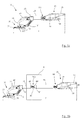
- FIGS. 1a and 1b show the long-neck sander according to the invention without extension unit (see. FIG. 1 a) or with extension unit ( FIG. 1 b)
- the long-necked sander according to the invention is generally indicated by the reference numeral 10. It comprises, in a known manner, a grinding unit 20 with a grinding head 22 and a drive unit 30.
- the drive unit 30 has an electric motor 32 (cf. FIG. 4 ) received in a housing 34.
- a disk-shaped brushing or grinding tool W is rotatably received on the grinding head via a tool spindle WS.
- a handle 36 extends at an end of the housing 34 facing away from the tool W.
- the electric motor 32 can be supplied in a known manner by accumulators (not shown) or by an external power source via an electrical line (not shown).
- the drive torque of the motor 32 is from an output shaft 14 (see. FIG. 4 ) via a rigid transmission shaft 16 (see. FIG. 4 ) and a flexible transmission shaft 18 (see. FIG. 4 ) are transmitted to the tool spindle WS of the grinding head 22 to drive the tool W in rotation.
- the grinding unit 20 comprises, in addition to the grinding head 22, a supporting frame 12 which supports the grinding head 22 with respect to a housing 26 of the grinding unit 20. From the housing 26 extends a flexible connecting line 24, in which the flexible transmission shaft 18 is received. Furthermore, at least one of the housing 26 extends, as can be seen in a plan view (cf. FIG. 3 ), preferably two suction lines 46, 48 to the grinding head 22 in order to achieve efficient extraction of dust particles produced during processing. From the housing 26 extends in the distal direction (with respect to the tool W) further comprises a connecting arm 28, within which the rigid transmission shaft 16 is guided (see. FIG. 4 ). The connecting arm 28 further comprises a suction channel 44, which is in fluid communication with the suction lines 46, 48 (see. FIG. 4 ). Then, when the grinding unit 20 is directly connected to the drive unit 30 via the connecting arm 28 (see FIG. FIG. 1 a) , the connecting arm 28 forms at its free end a proximal interface 50a to the drive unit 30.
- a connecting piece 38 for connecting a dust extraction (for example in the form of a vacuum cleaner) is formed.
- a suction opening 40 (see. FIG. 1 b) at the connecting piece 38
- Suction air is formed by a suction channel 42 formed inside the housing 34 (cf. FIG. 4 ), which is connected in a connected state of the drive unit 30 with the grinding unit 20 in alignment with the suction channel 44 of the grinding unit 20, so that an extraction from the workpiece to the connecting piece 38 can take place.
- the longitudinal extension of the long-necked sander 10 of the invention of a minimum length L1 are extended to a length L2.
- an extension unit 70 is provided between the grinding unit 20 and the drive unit 30.
- the extension unit 70 has a cylindrical shape and has connecting elements at its two free ends, which together with the corresponding connection elements of the grinding unit 20 or the connecting arm 28 and the drive unit 30 form a proximal interface 50b and a distal interface 60. How to use the Figures 1b . 2 .
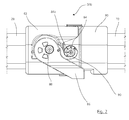
- 3 and 4 can better recognize, at the free end of the connecting arm 28 of the grinding unit 20, on the housing 34 of the drive unit 30 and at the two ends of the extension unit 70 fastening members for producing a detachable attachment of the extension unit 70 to the drive unit 30 and the grinding unit 20 are provided , These include a pin 84 attached to the extension unit 70 at the proximal interface 50b and attached to the drive unit 30 at the distal interface 60, and a tension hook 90 provided on the grinding unit 20 at the proximal interface 50b and at the distal interface 60 is attached to the extension unit 70.
- the proximal interface 50b and the distal interface 60 are designed in such a way that when the extension unit 70 (see FIG. FIG. 1a ), the respective attachment members attached to the drive unit 30 and the grinding unit 20 together form the proximal interface 50a. Accordingly, the proximal interface 50b and the distal interface 60 are in FIG Essentially identically formed, which is why in the following reference is made only to the proximal interface 50b in detail.
- the clamping hook 90 via a rotary lever 86 can be actuated, which is designed to be rotatable about an eccentric bearing 88.
- the tension hook 90 is pivoted by means of the rotary lever 86 via the pin 84. Due to its at least partially elastic formation of the clamping hook 90 slides over a dead center on the pin 84 and biases in its end position the pin 84 and the associated extension unit 70 against the connecting arm 28th
- an adjusting sleeve 84a is also provided on the pin 84, by means of which the user can adjust the bias or clamping force of the connection of the clamping hook 90 and the behind-engaged pin 84.
- the adjusting sleeve 84a surrounds the pin 84, wherein the receiving opening of the sleeve 84a for the pin 84 is arranged eccentrically thereto.
- a clip closure could also be provided, for example.
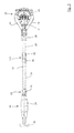
- the extension unit 70 comprises an extension tube 72 which extends along a central longitudinal axis M (see. FIG. 3 ). Within the extension tube 72, a connecting shaft 74 and a connecting channel 76 are arranged.
- the extension unit 70 is thus formed in the manner of a double tube, wherein the receptacle for the extension shaft 74 is separated from the extension channel 76 by a tube wall.
- the extension channel 76 connects the suction channel 44 of the connecting arm 28 with the Suction passage 42 of the motor housing 34.
- the extension shaft 74 connects the output shaft 14 with the transmission shaft 16 and thus enables transmission of a drive torque from the motor 32 to the tool spindle WS of the grinding unit 20.
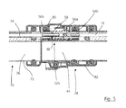
- FIG. 5 shows the proximal interface 50b in detail in a longitudinal sectional view.
- a coupling housing part 80 is formed, which serves with a corresponding coupling housing part 82 of the connecting arm 28 for releasably connecting and fastening the extension unit 70 with or on the connecting arm 28.
- the coupling housing or its parts can be made of plastic.
- the above-described components of the mounting arrangement, the pin 84, the adjusting sleeve 84a, the clamping hook 90 and the associated rotary lever 86 are formed in the embodiment shown on the respective housing parts 80, 82 to provide a particularly simple mounting arrangement.
- the coupling has a coupling member 52b of the extension unit 70 and a cooperating coupling member 54b of the grinding unit 20.
- the coupling member 52b comprises a first coupling element 56a, on the front side of which claws are formed. These engage in a form-fitting manner in claw elements of the cooperating coupling element 54b of the grinding unit 20 arranged on the face side.
- the coupling formed in the manner of a dog clutch is resiliently mounted on one side and has the coupling member 52b Accordingly, a spring 58 which is disposed between the first coupling element 56a and a second coupling element 56b of the coupling member 52b.
- the first coupling element 56a is rotatably connected to the extension shaft 74 for transmitting a driving torque from the extension shaft 74 to the cooperating coupling member 54b.
- the illustrated embodiment has the advantage of a particularly cost-effective production of the individual elements.
- the configuration of the distal interface 60 is largely identical to that of the proximal interface 50b.
- the clutch housing is formed by housing parts of the housing 34 of the drive unit and a coupling housing part 78.
- the clutch received therein comprises the coupling member 52a, which is provided at the distal free end of the extension unit, and the coupling member 54a, which is provided on the drive unit 30.
- the coupling member 52a corresponds to the structure of the coupling member 54b of the proximal interface 50b
- the coupling member 54a corresponds in its construction to the structure of the coupling member 52b of the proximal interface 50b.
Landscapes
- Engineering & Computer Science (AREA)
- Mechanical Engineering (AREA)
- Finish Polishing, Edge Sharpening, And Grinding By Specific Grinding Devices (AREA)
Applications Claiming Priority (2)
| Application Number | Priority Date | Filing Date | Title |
|---|---|---|---|
| DE102014108319 | 2014-06-13 | ||
| DE102014109583.9A DE102014109583A1 (de) | 2014-06-13 | 2014-07-09 | Langhalsschleifer |
Publications (2)
| Publication Number | Publication Date |
|---|---|
| EP2954977A1 true EP2954977A1 (fr) | 2015-12-16 |
| EP2954977A3 EP2954977A3 (fr) | 2016-03-16 |
Family
ID=53002613
Family Applications (1)
| Application Number | Title | Priority Date | Filing Date |
|---|---|---|---|
| EP15165362.3A Withdrawn EP2954977A3 (fr) | 2014-06-13 | 2015-04-28 | Ponceuse à bras girafe |
Country Status (2)
| Country | Link |
|---|---|
| EP (1) | EP2954977A3 (fr) |
| DE (1) | DE102014109583A1 (fr) |
Cited By (6)
| Publication number | Priority date | Publication date | Assignee | Title |
|---|---|---|---|---|
| CN108000301A (zh) * | 2018-01-04 | 2018-05-08 | 锐奇控股股份有限公司 | 手持式砂光机 |
| CN111168504A (zh) * | 2020-02-21 | 2020-05-19 | 金华市高就机电设备有限公司 | 一种墙壁打磨机及其使用方法 |
| WO2021089206A1 (fr) * | 2019-11-05 | 2021-05-14 | Festool Gmbh | Agencement de raccordement pour machine-outil guidée à la main, et machine-outil guidée à la main |
| WO2021089207A1 (fr) * | 2019-11-05 | 2021-05-14 | Festool Gmbh | Agencement de raccordement pour machine-outil guidée à la main, et machine-outil guidée à la main |
| US11867224B2 (en) | 2021-01-27 | 2024-01-09 | Black & Decker Inc. | Locking mechanism for two telescoping poles of a power tool |
| US11931851B2 (en) | 2019-10-23 | 2024-03-19 | Black & Decker Inc. | Pole sander |
Citations (5)
| Publication number | Priority date | Publication date | Assignee | Title |
|---|---|---|---|---|
| US4782632A (en) | 1987-10-01 | 1988-11-08 | William Matechuk | Drywall sander |
| AT1717U1 (de) | 1996-10-03 | 1997-10-27 | Preishuber Herbert | Handgeführte stabförmige vorrichtung mit rotierenden bürst- oder schleifwerkzeug |
| WO2006039415A2 (fr) * | 2004-09-29 | 2006-04-13 | Black & Decker Inc. | Ponceuse pour cloison seche |
| EP1970168A1 (fr) * | 2007-03-15 | 2008-09-17 | Festool GmbH | Barre de saisie d'une machine-outil manuelle |
| US20110306283A1 (en) * | 2010-06-11 | 2011-12-15 | Kresge David W | Multi-purpose extended reach tool |
Family Cites Families (2)
| Publication number | Priority date | Publication date | Assignee | Title |
|---|---|---|---|---|
| DE715127C (de) * | 1938-08-07 | 1941-12-15 | Fritz Seibel | Durch einen Drehmotor angetriebene Saege zum Rauben von Grubenstempeln |
| US4685252A (en) * | 1985-07-22 | 1987-08-11 | Ponce Felix C | Reciprocating sander |
-
2014
- 2014-07-09 DE DE102014109583.9A patent/DE102014109583A1/de not_active Ceased
-
2015
- 2015-04-28 EP EP15165362.3A patent/EP2954977A3/fr not_active Withdrawn
Patent Citations (6)
| Publication number | Priority date | Publication date | Assignee | Title |
|---|---|---|---|---|
| US4782632A (en) | 1987-10-01 | 1988-11-08 | William Matechuk | Drywall sander |
| AT1717U1 (de) | 1996-10-03 | 1997-10-27 | Preishuber Herbert | Handgeführte stabförmige vorrichtung mit rotierenden bürst- oder schleifwerkzeug |
| WO2006039415A2 (fr) * | 2004-09-29 | 2006-04-13 | Black & Decker Inc. | Ponceuse pour cloison seche |
| EP1793966B1 (fr) | 2004-09-29 | 2012-02-22 | Black & Decker, Inc. | Ponceuse pour cloison seche |
| EP1970168A1 (fr) * | 2007-03-15 | 2008-09-17 | Festool GmbH | Barre de saisie d'une machine-outil manuelle |
| US20110306283A1 (en) * | 2010-06-11 | 2011-12-15 | Kresge David W | Multi-purpose extended reach tool |
Cited By (8)
| Publication number | Priority date | Publication date | Assignee | Title |
|---|---|---|---|---|
| CN108000301A (zh) * | 2018-01-04 | 2018-05-08 | 锐奇控股股份有限公司 | 手持式砂光机 |
| US11931851B2 (en) | 2019-10-23 | 2024-03-19 | Black & Decker Inc. | Pole sander |
| WO2021089206A1 (fr) * | 2019-11-05 | 2021-05-14 | Festool Gmbh | Agencement de raccordement pour machine-outil guidée à la main, et machine-outil guidée à la main |
| WO2021089207A1 (fr) * | 2019-11-05 | 2021-05-14 | Festool Gmbh | Agencement de raccordement pour machine-outil guidée à la main, et machine-outil guidée à la main |
| CN113272100A (zh) * | 2019-11-05 | 2021-08-17 | 费斯托工具有限责任公司 | 用于手导式机械刀具的连接组件以及手导式机械刀具 |
| CN113272100B (zh) * | 2019-11-05 | 2023-08-04 | 费斯托工具有限责任公司 | 用于手导式机械刀具的连接组件以及手导式机械刀具 |
| CN111168504A (zh) * | 2020-02-21 | 2020-05-19 | 金华市高就机电设备有限公司 | 一种墙壁打磨机及其使用方法 |
| US11867224B2 (en) | 2021-01-27 | 2024-01-09 | Black & Decker Inc. | Locking mechanism for two telescoping poles of a power tool |
Also Published As
| Publication number | Publication date |
|---|---|
| EP2954977A3 (fr) | 2016-03-16 |
| DE102014109583A1 (de) | 2015-12-17 |
Similar Documents
| Publication | Publication Date | Title |
|---|---|---|
| EP2954977A1 (fr) | Ponceuse à bras girafe | |
| EP0977521B1 (fr) | PARTIE DE BROSSE POUR BROSSE à DENTS ELECTRIQUE | |
| DE60313379T2 (de) | Rotierendes Werkzeug mit biegsamer Welle mit Sperrstift und Endkappe | |
| WO2007039356A1 (fr) | Machine-outil electrique | |
| EP2104595B1 (fr) | Marteau perforateur et/ou burineur | |
| DE102006059633B4 (de) | Schlagbohrmaschine | |
| DE2804223A1 (de) | Zusatzhandgriff fuer eine motorisch angetriebene, insbesondere axiale schlaege ausfuehrende handwerkzeugmaschine | |
| EP2955435A1 (fr) | Ponceuse à bras girafe et unité d'éclairage associée | |
| DE102004051793A1 (de) | Chirurgisches Instrument mit winkligem Aufsatz | |
| DE202010008240U1 (de) | Multifunktions-Kraftwerkzeug | |
| DE102015105655B3 (de) | Spannvorrichtung für eine Rührwerkskugelmühle mit Riemen- oder Kettenantrieb und Rührwerkskugelmühle | |
| EP3000559A2 (fr) | Machine-outil et sa structure porteuse | |
| DE202009010986U1 (de) | Handbetätigter Antriebsmechanismus für eine Industrietür | |
| DE102012214938B4 (de) | Getriebeanordnung für eine angetriebene Werkzeugmaschine sowie Werkzeugmaschine mit einer solchen Getriebeanordnung | |
| DE102005054046B4 (de) | Gelenkschrauber | |
| DE10318563A1 (de) | Gelenkschrauber | |
| EP2704929B1 (fr) | Mécanisme d'arrêt | |
| DE102015112059B4 (de) | Langhalsschleifer | |
| DE202017101409U1 (de) | Hilfsgriff und Arbeitswerkzeug | |
| DE102006061632A1 (de) | Scheibenwischerantrieb | |
| DE4014752C2 (de) | Längsschneidarm für Vortriebs- und Abbauzwecke u. dgl. | |
| DE102017202469B3 (de) | Spindelstockanordnung für eine Werkzeugmaschine | |
| DE102011114399A1 (de) | Handwerkzeugmaschine | |
| DE202013100967U1 (de) | Linearantrieb | |
| EP3461594B1 (fr) | Dispositif d'entraînement pour une machine-outil entraînée |
Legal Events
| Date | Code | Title | Description |
|---|---|---|---|
| PUAI | Public reference made under article 153(3) epc to a published international application that has entered the european phase |
Free format text: ORIGINAL CODE: 0009012 |
|
| AK | Designated contracting states |
Kind code of ref document: A1 Designated state(s): AL AT BE BG CH CY CZ DE DK EE ES FI FR GB GR HR HU IE IS IT LI LT LU LV MC MK MT NL NO PL PT RO RS SE SI SK SM TR |
|
| AX | Request for extension of the european patent |
Extension state: BA ME |
|
| PUAB | Information related to the publication of an a document modified or deleted |
Free format text: ORIGINAL CODE: 0009199EPPU |
|
| PUAF | Information related to the publication of a search report (a3 document) modified or deleted |
Free format text: ORIGINAL CODE: 0009199SEPU |
|
| PUAL | Search report despatched |
Free format text: ORIGINAL CODE: 0009013 |
|
| D17D | Deferred search report published (deleted) | ||
| RIC1 | Information provided on ipc code assigned before grant |
Ipc: B24B 7/18 20060101AFI20160128BHEP |
|
| AK | Designated contracting states |
Kind code of ref document: A3 Designated state(s): AL AT BE BG CH CY CZ DE DK EE ES FI FR GB GR HR HU IE IS IT LI LT LU LV MC MK MT NL NO PL PT RO RS SE SI SK SM TR |
|
| AX | Request for extension of the european patent |
Extension state: BA ME |
|
| 17P | Request for examination filed |
Effective date: 20160916 |
|
| RBV | Designated contracting states (corrected) |
Designated state(s): AL AT BE BG CH CY CZ DE DK EE ES FI FR GB GR HR HU IE IS IT LI LT LU LV MC MK MT NL NO PL PT RO RS SE SI SK SM TR |
|
| 17Q | First examination report despatched |
Effective date: 20170120 |
|
| STAA | Information on the status of an ep patent application or granted ep patent |
Free format text: STATUS: THE APPLICATION IS DEEMED TO BE WITHDRAWN |
|
| 18D | Application deemed to be withdrawn |
Effective date: 20170801 |