EP2954769B2 - System and method for coordinated control of agricultural vehicle - Google Patents
System and method for coordinated control of agricultural vehicle Download PDFInfo
- Publication number
- EP2954769B2 EP2954769B2 EP15171799.8A EP15171799A EP2954769B2 EP 2954769 B2 EP2954769 B2 EP 2954769B2 EP 15171799 A EP15171799 A EP 15171799A EP 2954769 B2 EP2954769 B2 EP 2954769B2
- Authority
- EP
- European Patent Office
- Prior art keywords
- control system
- vehicle
- target
- harvester
- controller
- Prior art date
- Legal status (The legal status is an assumption and is not a legal conclusion. Google has not performed a legal analysis and makes no representation as to the accuracy of the status listed.)
- Active
Links
- 238000000034 method Methods 0.000 title description 54
- 230000033001 locomotion Effects 0.000 claims description 13
- 230000005540 biological transmission Effects 0.000 claims description 6
- 230000008569 process Effects 0.000 description 37
- 238000003032 molecular docking Methods 0.000 description 28
- 230000007704 transition Effects 0.000 description 17
- 238000010586 diagram Methods 0.000 description 12
- 238000004891 communication Methods 0.000 description 11
- 238000012546 transfer Methods 0.000 description 11
- 238000003306 harvesting Methods 0.000 description 10
- 230000000881 depressing effect Effects 0.000 description 8
- 230000002708 enhancing effect Effects 0.000 description 6
- 230000001133 acceleration Effects 0.000 description 4
- 230000000977 initiatory effect Effects 0.000 description 4
- 241000196324 Embryophyta Species 0.000 description 3
- 238000000926 separation method Methods 0.000 description 3
- 229920000742 Cotton Polymers 0.000 description 2
- 241000219146 Gossypium Species 0.000 description 2
- 241000209140 Triticum Species 0.000 description 2
- 235000021307 Triticum Nutrition 0.000 description 2
- 230000004913 activation Effects 0.000 description 2
- 230000008859 change Effects 0.000 description 2
- 239000000284 extract Substances 0.000 description 2
- 238000005065 mining Methods 0.000 description 2
- 238000012545 processing Methods 0.000 description 2
- 230000000007 visual effect Effects 0.000 description 2
- 235000004431 Linum usitatissimum Nutrition 0.000 description 1
- 240000006240 Linum usitatissimum Species 0.000 description 1
- 240000008042 Zea mays Species 0.000 description 1
- 235000005824 Zea mays ssp. parviglumis Nutrition 0.000 description 1
- 235000002017 Zea mays subsp mays Nutrition 0.000 description 1
- 235000013339 cereals Nutrition 0.000 description 1
- 235000005822 corn Nutrition 0.000 description 1
- 230000001419 dependent effect Effects 0.000 description 1
- 230000000994 depressogenic effect Effects 0.000 description 1
- 238000001514 detection method Methods 0.000 description 1
- 239000000446 fuel Substances 0.000 description 1
- 239000000463 material Substances 0.000 description 1
- 238000005259 measurement Methods 0.000 description 1
- 239000000203 mixture Substances 0.000 description 1
- 230000003287 optical effect Effects 0.000 description 1
- 230000035945 sensitivity Effects 0.000 description 1
- 238000001228 spectrum Methods 0.000 description 1
Images


Classifications
-
- G—PHYSICS
- G05—CONTROLLING; REGULATING
- G05D—SYSTEMS FOR CONTROLLING OR REGULATING NON-ELECTRIC VARIABLES
- G05D1/00—Control of position, course, altitude or attitude of land, water, air or space vehicles, e.g. using automatic pilots
- G05D1/02—Control of position or course in two dimensions
- G05D1/021—Control of position or course in two dimensions specially adapted to land vehicles
- G05D1/0276—Control of position or course in two dimensions specially adapted to land vehicles using signals provided by a source external to the vehicle
-
- A—HUMAN NECESSITIES
- A01—AGRICULTURE; FORESTRY; ANIMAL HUSBANDRY; HUNTING; TRAPPING; FISHING
- A01B—SOIL WORKING IN AGRICULTURE OR FORESTRY; PARTS, DETAILS, OR ACCESSORIES OF AGRICULTURAL MACHINES OR IMPLEMENTS, IN GENERAL
- A01B69/00—Steering of agricultural machines or implements; Guiding agricultural machines or implements on a desired track
- A01B69/007—Steering or guiding of agricultural vehicles, e.g. steering of the tractor to keep the plough in the furrow
- A01B69/008—Steering or guiding of agricultural vehicles, e.g. steering of the tractor to keep the plough in the furrow automatic
-
- A—HUMAN NECESSITIES
- A01—AGRICULTURE; FORESTRY; ANIMAL HUSBANDRY; HUNTING; TRAPPING; FISHING
- A01D—HARVESTING; MOWING
- A01D41/00—Combines, i.e. harvesters or mowers combined with threshing devices
-
- G—PHYSICS
- G05—CONTROLLING; REGULATING
- G05D—SYSTEMS FOR CONTROLLING OR REGULATING NON-ELECTRIC VARIABLES
- G05D1/00—Control of position, course, altitude or attitude of land, water, air or space vehicles, e.g. using automatic pilots
- G05D1/02—Control of position or course in two dimensions
- G05D1/021—Control of position or course in two dimensions specially adapted to land vehicles
- G05D1/0287—Control of position or course in two dimensions specially adapted to land vehicles involving a plurality of land vehicles, e.g. fleet or convoy travelling
- G05D1/0291—Fleet control
-
- G—PHYSICS
- G05—CONTROLLING; REGULATING
- G05D—SYSTEMS FOR CONTROLLING OR REGULATING NON-ELECTRIC VARIABLES
- G05D13/00—Control of linear speed; Control of angular speed; Control of acceleration or deceleration, e.g. of a prime mover
- G05D13/62—Control of linear speed; Control of angular speed; Control of acceleration or deceleration, e.g. of a prime mover characterised by the use of electric means, e.g. use of a tachometric dynamo, use of a transducer converting an electric value into a displacement
-
- A—HUMAN NECESSITIES
- A01—AGRICULTURE; FORESTRY; ANIMAL HUSBANDRY; HUNTING; TRAPPING; FISHING
- A01B—SOIL WORKING IN AGRICULTURE OR FORESTRY; PARTS, DETAILS, OR ACCESSORIES OF AGRICULTURAL MACHINES OR IMPLEMENTS, IN GENERAL
- A01B79/00—Methods for working soil
- A01B79/02—Methods for working soil combined with other agricultural processing, e.g. fertilising, planting
Definitions
- the invention relates generally to a system and method for coordinated control of agricultural vehicles.
- a harvester may be used to harvest agricultural crops, such as cotton, wheat, flax, or other crops.
- components e.g., drums, spindles, blades, etc.
- the harvester then conveys the removed portions of the agricultural crops (e.g., agricultural products) to an internal storage compartment, either directly or via a processing device configured to remove undesirable portions of the agricultural products.
- the internal storage compartment is typically unloaded multiple times during the harvesting process.
- One method of unloading the internal storage compartment involves periodically transferring the agricultural product to a mobile storage compartment while the harvester is in motion.
- the mobile storage compartment is towed by a haul vehicle to a position proximate to the harvester.
- the operator of the haul vehicle aligns the storage compartment with a conveyor outlet of the harvester and substantially matches the speed of the harvester.
- the harvester operator then initiates transfer of the agricultural product from the harvester to the mobile storage compartment, thereby unloading the internal storage compartment of the harvester.
- WO-A1-2012/110508 discloses a control system for an agricultural vehicle, comprising a first transceiver configured to receive a first signal from a second transceiver of a target vehicle, wherein the first signal is indicative of a first determined position and a first determined velocity of the target vehicle.
- Highly skilled drivers typically operate the haul vehicles due to the complexity associated with aligning the mobile storage compartment with the harvester and matching the speed of the harvester. Employing such drivers may increase the costs associated with the harvesting process and/or may delay the harvesting process due to the limited availability of these drivers. Furthermore, employing less skilled drivers to operate the haul vehicles may result in agricultural product loss due to misalignment of the mobile storage compartment with the harvester and/or mismatched operating speeds. As a result, the efficiency of the harvesting process may be reduced.
- a control system for an agricultural vehicle having the features of claim 1.
- control system preferably includes a spatial locating device mounted on the agricultural vehicle and configured to determine a second determined position and a second determined velocity of the agricultural vehicle.
- control system includes an automated steering control system configured to control a direction of movement of the agricultural vehicle, and an automated speed control system configured to control a speed of the agricultural vehicle.
- the control system also includes a controller communicatively coupled to the first transceiver, to the spatial locating device, to the automated steering control system, and to the automated speed control system.
- the controller is configured to automatically control the agricultural vehicle by determining a target position and a target velocity of the agricultural vehicle based at least in part on the first determined position and the first determined velocity of the target vehicle, determining a route to the target position based at least in part on the target position, the second determined position, and the second determined velocity, instructing the automated steering control system and the automated speed control system to direct the agricultural vehicle toward the target position along the route, and instructing the automated steering control system and the automated speed control system to substantially maintain the target position and the target velocity upon substantially reaching the target position.
- a method for controlling an agricultural vehicle includes receiving a first signal indicative of a first determined position and a first determined velocity of a target vehicle. The method also includes determining a target position and a target velocity of the agricultural vehicle based at least in part on the first determined position and the first determined velocity of the target vehicle. In addition, the method includes instructing an automated steering control system and an automated speed control system to direct the agricultural vehicle toward the target position, and instructing the automated steering control system and the automated speed control system to substantially maintain the target position and the target velocity upon substantially reaching the target position.
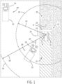
- FIG. 1 is a top view of an embodiment of an agricultural harvester and an agricultural product transportation system, in which the agricultural product transportation system is configured to automatically dock with the agricultural harvester.
- the agricultural harvester 10 includes a row of harvesting units 12 positioned on a front end of a chassis 14 and an internal storage compartment 16 coupled to the chassis 14.
- the harvesting units 12 engage unharvested plants 20 and extract various agricultural products (e.g., corn, wheat, cotton, etc.) from the plants.
- These agricultural products are transferred to the internal storage compartment 16, either directly or via a processing device configured to remove undesirable portions of the agricultural products.
- the remaining portions of the plants remain in the field as agricultural residue 22.
- the harvester 10 includes a conveyor 24 configured to transfer the agricultural product to a mobile storage compartment while the harvester is in motion.
- the conveyor 24 may include an auger, a conveyor belt, or other suitable device configured to transfer the agricultural product from the internal storage compartment 16 to an outlet 26.
- the mobile storage compartment may be automatically aligned with the conveyor outlet 26, thereby enhancing the efficiency of the harvester unloading process. While the illustrated agricultural harvester 10 is a self-propelled vehicle, it should be appreciated that, in certain embodiments, the agricultural harvester may be towed behind a tractor or other work vehicle.
- the illustrated agricultural harvester 10 includes an internal storage compartment 16, it should be appreciated that the internal storage compartment may be omitted in certain harvester configurations. In such configurations, the harvester may continuously transfer agricultural product to the mobile storage compartment as the harvester extracts and processes the agricultural products.
- an agricultural product transportation system 28 is configured to receive the agricultural product from the harvester 10.
- the product transportation system 28 includes a haul vehicle 30, such as the illustrated tractor, and a mobile storage compartment 32 (e.g., grain cart).
- the haul vehicle 30 includes a controller configured to automatically direct the storage compartment along a route 34 to a target position adjacent to the harvester 10. That is, the controller may automatically control the haul vehicle 10 during a docking process, thereby positioning the storage compartment in a location that enhances the transfer efficiency of the agricultural product from the harvester to the storage compartment.
- the controller is configured to determine a target position and a target velocity of the haul vehicle based at least in part on a determined position and a determined velocity of the harvester 10.
- the controller is also configured to instruct an automated steering control system and an automated speed control system to direct the haul vehicle toward the target position. Once the haul vehicle substantially reaches the target position, the controller is configured to instruct the automated steering control system and the automated speed control system to substantially maintain the target position and the target velocity.
- the target position corresponds to a position that substantially aligns the conveyor outlet 26 with a target point on the storage compartment 32. Accordingly, with the haul vehicle located at the target position, the agricultural product may be transferred from the harvester 10 to the storage compartment 32 while the vehicles are in motion. Because the controller automatically maintains the position of the storage compartment relative to the conveyor outlet during the unloading process, the possibility of agricultural product loss is substantially reduced or eliminated, thereby increasing the efficiency of the harvesting process.
- a range 38 of the area of communication 36 may be dependent on the broadcast power of the transceivers, the sensitivity of the transceivers, and/or the communication frequency, among other factors.
- each transceiver is configured to transmit data at a fixed interval (e.g., 50 Hz, 20 Hz, 10 Hz, 5 Hz, 1 Hz, 0.5 Hz, 0.1 Hz, etc.).
- the data may include a position of the vehicle, a velocity of the vehicle, a steering angle of the vehicle, an orientation of the vehicle, and/or an identity of the vehicle, among other parameters.
- each transceiver may be configured to retransmit data received from another transceiver. For example, the haul vehicle closer to the harvester may receive a signal from the harvester, and then retransmit the signal to the haul vehicle farther from the harvester, thereby effectively extending the communication range of each transceiver.
- an operator of the haul vehicle provides input to a user interface, thereby instructing the controller to enable automatic control of the haul vehicle.
- the controller instructs the automated steering control system and the automated speed control system to direct the haul vehicle toward the target position. For example, if the harvester is positioned in front of the haul vehicle, the automated speed control system may increase the speed of the haul vehicle. Conversely, if the harvester is positioned behind the haul vehicle, the automated speed control system may stop the haul vehicle until the harvester reaches a docking position.
- the steering control system may adjust wheel angles, for example, to steer the haul vehicle toward the harvester.
- the controller instructs the automated steering control system and the automated speed control system to substantially maintain the target position and the target velocity, thereby facilitating transfer of agricultural product from the harvester to the storage compartment.
- FIG. 2 is a schematic diagram of an embodiment of an agricultural harvester 10 and a haul vehicle 30, which may be employed within the agricultural product transportation system of FIG. 1 .
- the haul vehicle 30 includes a control system 43 having a first transceiver 44 configured to receive a first signal from a second transceiver 46 of a target vehicle, such as the illustrated agricultural harvester 10.
- the first signal is indicative of a first determined position (e.g., three-dimensional position vector) and a first determined velocity (e.g., three-dimensional velocity vector) of the harvester 10.
- the first and second transceivers may operate at any suitable frequency range within the electromagnetic spectrum.
- the transceivers may broadcast and receive radio waves within a frequency range of about 1 GHz to about 10 GHz.
- the first and second transceivers may utilize any suitable communication protocol, such as a standard protocol (e.g., Wi-Fi, Bluetooth, etc.) or a proprietary protocol.
- position refers to a position vector, such as a one, two, or three-dimensional position vector.
- a two-dimensional position vector may include latitude and longitude
- a three-dimensional position vector may include latitude, longitude, and altitude/elevation.
- the position vector may be represented in a rectangular, polar, cylindrical, or spherical coordinate system, among other suitable coordinate systems.
- velocity e.g., determined velocity, target velocity, etc. refers to a velocity vector, such as a one, two, or three-dimensional velocity vector.
- a one-dimensional velocity vector may include speed (e.g., ground speed), a two-dimensional velocity vector may include speed (e.g., ground speed) and heading within a plane (e.g., along a ground plane), and a three-dimensional velocity vector may include speed and heading within a three-dimensional space.
- the velocity vector may be represented in a rectangular, polar, cylindrical, or spherical coordinate system, among other suitable coordinate systems.
- the velocity may be represented as a unit/normalized vector, i.e., a vector having a unit magnitude.
- the magnitude e.g., speed
- a two-dimensional velocity unit vector may be representative of heading within a plane (e.g., along a ground plane)
- a three-dimensional velocity unit vector may be representative of heading within a three-dimensional space.
- the haul vehicle control system 43 also includes a spatial locating device 48, which is mounted to the haul vehicle 30 and configured to determine a second determined position and a second determined velocity of the haul vehicle 30.
- the spatial locating device may include any suitable system configured to measure the position and velocity of the haul vehicle, such as a global positioning system (GPS), for example.
- GPS global positioning system
- the spatial locating device 48 may be configured to measure the position and velocity of the haul vehicle relative to a fixed point within a field (e.g., via a fixed radio transceiver).
- the spatial locating device 48 may be configured to measure the position and velocity of the haul vehicle relative to a fixed global coordinate system (e.g., via the GPS) or a fixed local coordinate system.
- the first transceiver 44 is configured to broadcast a second signal indicative of the second determined position and/or the second determined velocity to other vehicles within the area of communication.
- the second signal from each haul vehicle may be utilized to determine which vehicle is closest to the harvester, thereby enabling the closest haul vehicle to dock with the harvester while the remaining vehicles wait for a subsequently unloading cycle.
- the haul vehicle control system 43 includes an orientation sensor 49 configured to determine a pitch angle, a yaw angle, and/or a roll angle of the haul vehicle.
- the orientation senor 49 may include a gyroscope or other sensor configured to monitor the orientation of the haul vehicle 30.
- the orientation sensor 49 is also configured to determine a pitch rate, a yaw rate, and/or a roll rate.
- the haul vehicle control system 43 is configured to compare the orientation (e.g., pitch angle, yaw angle, and/or roll angle) of the haul vehicle 30 to a measured orientation (e.g., pitch angle, yaw angle, and/or roll angle) of the harvester 10 to establish a relative orientation that may be utilized to enhance the accuracy of the docking process.
- orientation e.g., pitch angle, yaw angle, and/or roll angle
- a measured orientation e.g., pitch angle, yaw angle, and/or roll angle
- control system 43 includes an automated steering control system 50 configured to control a direction of movement of the haul vehicle 30, and an automated speed control system 52 configured to control a speed of the haul vehicle 30.
- control system 43 includes a controller 56 communicatively coupled to the first transceiver 44, to the spatial locating device 48, to the automated steering control system 50, and to the automated speed control system 52.
- the controller 56 is configured to automatically control the haul vehicle 30 during docking and while docked with the harvester, thereby enhancing transfer efficiency of the agricultural product to the storage compartment.
- the controller 56 is configured to determine a target position and a target velocity of the haul vehicle based at least in part on the first determined position and the first determined velocity of the harvester.
- the controller 56 is also configured to determine a route to the target position based at least in part on the target position, the second determined position of the haul vehicle, and the second determined velocity of the haul vehicle. Once the route is determined, the controller is configured to instruct the automated steering control system and the automated speed control system to direct the haul vehicle toward the target position along the route. Upon substantially reaching the target position, the controller is configured to instruct the automated steering control system and the automated speed control system to substantially maintain the target position and the target velocity.
- the control system described herein may be more efficient than control systems that utilize the position of the harvester alone to facilitate docking.
- the haul vehicle control system may utilize the determined velocity of the harvester to determine an expected position of the harvester at the time of docking.
- the target position and the route to the target position may be determined based on the expected position instead of the instantaneous position.
- the efficiency of the docking process may be enhanced, thereby reducing the duration and costs associated with harvesting operations.
- steering angle of the harvester, orientation of the harvester, heading of the harvester, and/or acceleration of the harvester may also be utilized to determine the target position and the route to the target position, thereby further enhancing the efficiency of the docking process.
- the target position is laterally and/or longitudinally offset relative to the harvester from the first determined position.
- a target point may be established on the storage compartment (e.g., at an approximate center point of the storage compartment).
- the haul vehicle controller 56 may determine a target position that substantially aligns the target point with the conveyor outlet of the harvester, thereby facilitating efficient transfer of agricultural product from the harvester to the storage compartment.
- the controller 56 is configured to determine a distance between the haul vehicle and the harvester based on the first determined position of the harvester and the second determined position of the haul vehicle. If the distance is less than or equal to the engagement distance, the controller 56 is configured to enable automatic control of the haul vehicle. Otherwise, the automatic control is disabled. In certain embodiments, upon detection of a separation distance less than or equal to the engagement distance, the controller 56 is configured to instruct a user interface to present an indication to an operator that automatic control is enabled. The operator may then initiate automatic control (e.g., via the user interface), thereby instructing the controller to direct the haul vehicle toward the target position.
- the controller 56 is an electronic controller having electrical circuitry configured to process data from the transceiver 44, the spatial locating device 48, and/or other components of the control system 43.
- the controller 56 include a processor, such as the illustrated microprocessor 58, and a memory device 60.
- the controller 56 may also include one or more storage devices and/or other suitable components.
- the processor 58 may be used to execute software, such as software for controlling the haul vehicle 30, and so forth.
- the processor 58 may include multiple microprocessors, one or more "general-purpose" microprocessors, one or more special-purpose microprocessors, and/or one or more application specific integrated circuits (ASICS), or some combination thereof.
- the processor 58 may include one or more reduced instruction set (RISC) processors.
- RISC reduced instruction set
- the memory device 60 may include a volatile memory, such as random access memory (RAM), and/or a nonvolatile memory, such as ROM.
- the memory device 60 may store a variety of information and may be used for various purposes.
- the memory device 60 may store processor-executable instructions (e.g., firmware or software) for the processor 58 to execute, such as instructions for controlling the haul vehicle 30.
- the storage device(s) e.g., nonvolatile storage
- the storage device(s) may include read-only memory (ROM), flash memory, a hard drive, or any other suitable optical, magnetic, or solid-state storage medium, or a combination thereof.
- the storage device(s) may store data (e.g., position data, identification data, etc.), instructions (e.g., software or firmware for controlling the haul vehicle, etc.), and any other suitable data.
- the automated steering control system 50 includes a wheel angle control system 62, a differential braking system 64, and a torque vectoring system 66.
- the wheel angle control system 62 may automatically rotate one or more wheels of the haul vehicle (e.g., via hydraulic actuators) to steer the haul vehicle along a desired route.
- the wheel angle control system 62 may rotate front wheels, rear wheels, and/or intermediate wheels of the haul vehicle, either individually or in groups.
- the differential braking system 64 may independently vary the braking force on each lateral side of the haul vehicle to direct the haul vehicle along the desired route.
- the torque vectoring system 66 may differentially apply torque from an engine to wheels and/or tracks on each lateral side of the haul vehicle, thereby directing the haul vehicle along a desired route. While the illustrated steering control system 50 includes the wheel angle control system 62, the differential braking system 64, and the torque vectoring system 66, it should be appreciated that alternative embodiments may include one or two of these systems, in any suitable combination. Further embodiments may include an automated steering control system 50 having other and/or additional systems to facilitate directing the haul vehicle along the desired route.
- the automated speed control system 52 includes an engine output control system 68, a transmission control system 70, and a braking control system 72.
- the engine output control system 68 is configured to vary the output of the engine to control the speed of the haul vehicle.
- the engine output control system 68 may vary a throttle setting of the engine, a fuel/air mixture of the engine, a timing of the engine, and/or other suitable engine parameters to control engine output.
- the transmission control system 70 may adjust gear selection within a transmission to control the speed of the haul vehicle.
- the braking control system 72 may adjust braking force, thereby controlling the speed of the haul vehicle 30.
- automated speed control system 52 includes the engine output control system 68, the transmission control system 70, and the braking control system 72, it should be appreciated that alternative embodiments may include one or two of these systems, in any suitable combination. Further embodiments may include an automated speed control system 52 having other and/or additional systems to facilitate adjusting the speed of the haul vehicle.
- the haul vehicle control system 43 includes a user interface 74 communicatively coupled to the controller 56.
- the user interface 74 is configured to selectively instruct the controller 56 to automatically control the haul vehicle based on operator input. For example, the operator may position the haul vehicle within the area of engagement, and then activate the automatic docking process via input to the user interface 74.
- the user interface includes a display 76 configured to present information to the operator, such as whether the haul vehicle is within the area of communication, whether the haul vehicle is within the area of engagement, and whether conditions for automatic docking have been satisfied, among other parameters.
- the user interface 74 may enable the operator to adjust the target point while the haul vehicle is docked with the harvester.
- the haul vehicle 30 includes manual controls 78 configured to enable an operator to control the haul vehicle while the automatic control system is disengaged.
- the manual controls 78 may include manual steering control, manual transmission control, and/or manual braking control, among other controls.
- the manual controls 78 are communicatively coupled to the controller 56.
- the controller 56 is configured to disengage automatic control of the haul vehicle upon receiving a signal indicative of manual control of the haul vehicle. Accordingly, if an operator controls the haul vehicle manually, the automatic docking/docked process terminates, thereby restoring control of the haul vehicle to the operator.
- the harvester 10 includes a control system 79 having a spatial locating device 80, which is mounted to the harvester 10 and configured to determine the first determined position and the first determined velocity of the agricultural harvester 10.
- the harvester spatial locating device 80 may include any suitable system configured to measure the position and velocity of the harvester, such as a global positioning system (GPS), for example.
- GPS global positioning system
- the spatial locating device 80 may be configured to measure the position and velocity of the harvester relative to a fixed point within a field (e.g., via a fixed radio transceiver).
- the spatial locating device 80 may be configured to measure the position and velocity of the harvester relative to a fixed global coordinate system (e.g., via the GPS) or a fixed local coordinate system.
- the spatial locating device 80 is communicatively coupled to a controller 82 of the harvester control system 79. Similar to the haul vehicle controller 56, the harvester controller 82 includes a processor, such as the illustrated microprocessor 84, and a memory device 86.
- the controller 82 is communicatively coupled to the second transceiver 46 and configured to transmit position and velocity information from the spatial locating device 80 to the transceiver 46, thereby generating the first signal indicative of the first determined position and the first determined velocity of the agricultural harvester 10.
- the harvester control system 79 also includes a steering angle sensor 88 and an orientation sensor 90.
- the steering angle sensor 88 is configured to output a signal indicative of a measured and/or determined steering angle.
- the steering angle sensor 88 may be configured to measure an angle of certain wheels (e.g., front wheels, rear wheels, etc.) relative to the chassis of the harvester.
- the steering angle sensor 88 may also be configured to measure differential braking forces (e.g., the braking force applied to each lateral side of the harvester).
- the steering angle sensor 88 may be configured to measure torque applied to each lateral side of the harvester (e.g., torque applied to a left wheel/track and torque applied to a right wheel/track).
- the steering angle sensor 88 is communicatively coupled to the controller 82.
- the controller 82 is configured to receive the signal indicative of steering angle from the sensor 88, and to transmit the signal to the transceiver 46.
- the transceiver 46 is configured to incorporate the steering angle information into the first signal to the haul vehicle.
- the steering angle information may enable the haul vehicle control system to more accurately predict the expected position of the harvester, thereby enhancing the efficiency of the docking process.
- the orientation sensor 90 is configured to output a signal indicative of a measured pitch angle, a measured yaw angle, and/or a measured roll angle of the harvester.
- the orientation senor 90 may include a gyroscope or other sensor configured to monitor the orientation of the harvester 10.
- the orientation sensor 90 is also configured to determine a pitch rate, a yaw rate, and/or a roll rate.
- the orientation sensor 90 is communicatively coupled to the controller 82.
- the controller 82 is configured to receive the signal indicative of the orientation measurements from the orientation sensor 90, and to transmit the signal to the transceiver 46.
- the transceiver 46 is configured to incorporate the orientation information into the first signal to the haul vehicle.
- the orientation information may enable the haul vehicle control system to more accurately predict the expected position of the harvester, thereby enhancing the efficiency of the docking process.
- the harvester control system includes a steering angle sensor 88 and an orientation sensor 90, it should be appreciated that one or both of these sensors may be omitted in certain embodiments.
- the harvester may include additional sensors configured to measure other parameters associated with operation of the harvester.
- the harvester control system may include an electronic compass configured to output a signal indicative of heading.
- the harvester control system may include an accelerometer configured to output a signal indicative of acceleration (e.g., three-dimensional acceleration) of the harvester. The output from such sensors may be incorporated within the first signal to the haul vehicle.
- the heading information may be incorporated within the first determined velocity.
- the heading and/or acceleration information may enable the haul vehicle control system to more accurately predict the expected position of the harvester, thereby enhancing the efficiency of the docking process. While an electronic compass and an accelerometer are described above, it should be appreciated that, in further embodiments, the harvester control system may include other and/or additional sensors.
- the harvester control system 79 includes a user interface 92 configured to receive input from an operator of the agricultural vehicle.
- the user interface 92 includes a display 94 configured to present information to the harvester operator and/or to receive input from the operator.
- the user interface 92 is communicatively coupled to the controller 82.
- the controller 82 is configured to calibrate alignment of the conveyor outlet of the harvester with a storage compartment coupled to the haul vehicle.
- the controller 82 is configured to receive a first signal from the user interface 92 indicative of alignment of the conveyor outlet with a first desired point on the storage compartment, and to determine a first position of the storage compartment relative to the agricultural harvester upon receiving the first signal.
- the controller 82 is also configured to receive a second signal from the user interface 92 indicative of alignment of the conveyor outlet with a second desired point on the storage compartment, diagonally opposite the first desired point, and to determine a second position of the storage compartment relative to the agricultural harvester upon receiving the second signal.
- the controller 82 is configured to establish a bounding rectangle having a first corner at the first desired point and a second corner at the second desired point based on the first and second positions, and to establish a target point at a center of the bounding rectangle.
- the controller 82 is configured to output a signal to the second transceiver 46 indicative of a position of the first corner of the bounding rectangle relative to the storage compartment, a position of the second corner of the bounding rectangle relative to the storage compartment, and a position of the target point relative to the storage compartment.
- the transceiver 46 is configured to incorporate data corresponding to these positions into the signal transmitted to the first transceiver 44.
- the haul vehicle control system 43 may utilize the positions of the first and second corners of the bounding rectangle and/or the position of the target point, in addition to the position and velocity of the harvester, to determine the target position and/or the target velocity of the haul vehicle.
- the haul vehicle control system 43 may determine a target position that substantially aligns the target point with the conveyor outlet of the harvester. In addition, because the controller 82 outputs a signal indicative of the positions of the first and second corners of the bounding rectangle and the position of the target point upon completion of the calibration process, the haul vehicle control system 43 may detect a successful calibration upon receiving the signal. In certain embodiments, the haul vehicle control system 43 may not initiate the docking process until a successful calibration is detected.
- the controller 82 is configured to laterally and/or longitudinally adjust the position of the target point based on input from the user interface 92. For example, an operator of the harvester may periodically adjust the target position during the unloading process, thereby establishing a substantially even distribution of agricultural product within the storage compartment.
- the updated position is transmitted to the haul vehicle control system 43 (e.g., via the transceiver 46).
- the haul vehicle control system 43 adjusts the target position such that the conveyor outlet is aligned with the adjusted target point.
- the operator of the haul vehicle may also adjust the position of the target point via the user interface 74.
- the position of the target point may be limited to locations within the bounding rectangle, thereby substantially reducing or eliminating the possibility of product loss during the unloading process.
- the agricultural harvester 10 includes a product deliver system 96 configured to transfer agricultural product from the harvester to the storage compartment.
- the product deliver system 96 is communicatively coupled to the controller 82.
- the controller 82 is configured to automatically engage product flow from the conveyor outlet to the storage compartment (e.g., via activation of the product deliver system 96) while the conveyor outlet is within the bounding rectangle.
- the controller 82 is configured to automatically engage product flow from the conveyor outlet to the storage compartment (e.g., via activation of the product deliver system 96) while the conveyor outlet is within a threshold range of the target point.
- FIG. 3 is a state diagram of an embodiment of a technique 98 for controlling a haul vehicle.
- the control system Prior to initiating the docking process, the control system is in an initialization state 100. As indicated by the arrow 102, booting the control system transitions the control system from the initialization state 100 to an "off' state 104. Switching the control system on, as indicated by the arrow 106 transitions the control system from the "off' state 104 to a "safe" state 108. Conversely, switching the control system off, as indicated by the arrow 110, transitions the control system to the "off' state 104. If no faults are detected within the system, as indicated by the arrow 112, the control system transitions to a "ready to dock" state 114.
- the user interface may provide an indication to the operator that the haul vehicle is ready to dock.
- the control system transitions to a "docking" state 122.
- the automated steering control system and the automated speed control system direct the haul vehicle toward the target position. If the operator controls the haul vehicle manually, as indicated by the arrow 124, the control system transitions to the "safe" state 108, thereby disengaging automatic control of the haul vehicle.
- the control system transitions to an "alarm" state 128.
- the user interface may present the operator with a visual and/or audible indication that a fault is detected and/or the nature of the fault.
- the automatic control is disengaged, which transitions the control system to the "safe" state 108.
- the control system transitions to the "off state 104.
- the control system transitions to the "docked" state 134.
- the predetermined time interval may be about 1 second, about 2 seconds, about 3 seconds, about 4 seconds, or more.
- the automated steering control system and the automated speed control system While in the "docked" state 134, the automated steering control system and the automated speed control system substantially maintain the target position and the target velocity. If the operator controls the haul vehicle manually, as indicated by the arrow 136, the control system transitions to the "safe" state 108, thereby disengaging automatic control of the haul vehicle.
- the control system transitions to an "alarm" state 128.
- the user interface may present the operator with a visual and/or audible indication that a fault is detected and/or the nature of the fault.
- the automatic control is disengaged, which transitions the control system to the "safe" state 108.
- the control system transitions to the "off' state 104.
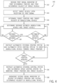
- FIG. 4 is a flow diagram of an embodiment of a method 140 for controlling an agricultural vehicle, such as the haul vehicle.
- a first signal indicative of a first determined position and a first determined velocity of a target vehicle is received.
- the first signal may be transmitted from a second transceiver of the target vehicle and received by a first transceiver of the agricultural vehicle.
- the target vehicle is detected upon reception of the first signal, as represented by block 144.
- a target position and a target velocity of the agricultural vehicle is determined based on the first determined position and the first determined velocity of the target vehicle, as represented by block 146.
- a steering angle of the target vehicle, a pitch angle of the target vehicle, a roll angle of the target vehicle, and/or a yaw angle of the target vehicle are also utilized to determine the target position and the target velocity of the agricultural vehicle. For example, as previously discussed, an expected position of the target vehicle at the time of docking may be determined based on the velocity, steering angle, and/or orientation of the target vehicle. Accordingly, the target position may be determined based on the expected position instead of the instantaneous position.
- a distance between the agricultural vehicle and the target vehicle is determined. The distance is then compared to an engagement distance, as represented by block 150. If the distance is less than or equal to the engagement distance, automatic control of the agricultural vehicle is enabled.
- an automated steering control system and an automated speed control system are instructed to direct the agricultural vehicle toward the target position, as represented by block 152. For example, if the target vehicle is positioned in front of the agricultural vehicle, the automated speed control system may increase the speed of the agricultural vehicle. Conversely, if the target vehicle is positioned behind the agricultural vehicle, the automated speed control system may stop the agricultural vehicle until the target vehicle reaches a docking position.
- the steering control system may adjust wheel angles, for example, to steer the agricultural vehicle toward the target position.
- the position of the agricultural vehicle is then compared to the target position, as represented by block 154. If the target position is reached, the automated steering control system and the automated speed control system are instructed to maintain the target position and the target velocity, as represented by block 156. For example, if the speed of the target vehicle increases, the automated speed control system may increase the speed of the agricultural vehicle to match the speed of the target vehicle. Similarly, if the target vehicle initiates a turn, the automated steering control system may direct the agricultural vehicle to match the movement of the target vehicle. As a result, alignment between the conveyor outlet and the storage compartment may be maintained throughout the unloading process, thereby substantially reducing or eliminating agricultural product loss and/or increasing the efficiency of the unloading process.
- a second signal indicative of a second determined position and a second determined velocity of the agricultural vehicle is broadcast to other agricultural vehicles within the area of communication.
- Other agricultural vehicles may utilize this information to determine which vehicle is closest to the target vehicle. For example, if multiple agricultural vehicles are within the area of engagement, each vehicle may compare its position, and the position of the other vehicles, to the position of the target vehicle.
- the control system of the vehicle closest to the target vehicle transitions to the "docking" state, while the control systems of the farther vehicles remain in a "ready to dock” state. In this manner, the closest vehicle docks with the target vehicle, while the remaining vehicles wait for a subsequent unloading cycle.
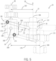
- FIG. 5 is a schematic diagram of an embodiment of an agricultural harvester 10 and an agricultural product transportation system 28.
- the harvester controller is configured to calibrate alignment of the conveyor outlet 26 with the storage compartment 32, thereby enabling the haul vehicle controller to establish a target position that facilitates efficient transfer of the agricultural product from the harvester to the storage compartment.
- the harvester controller is configured to receive a first signal from a user interface indicative of alignment of the conveyor outlet 26 with a first desired point 160 on the storage compartment 32.
- an operator of the haul vehicle 30 may position the storage compartment 32 (e.g., via manual control of the haul vehicle) such that the conveyor outlet 26 is aligned with the first desired point 160 at a front left portion of the storage compartment 32, as illustrated by the harvester 10 in solid lines.
- an operator of the harvester 10 may position the harvester 10 (e.g., via manual control of the harvester) such that the conveyor outlet 26 is aligned with the first desired point 160.
- the operator of the harvester 10 or the operator of the haul vehicle 30 depresses a button on the user interface that transmits the first signal indicative of alignment to the harvester controller.
- the harvester controller determines a first position of the storage compartment 32 relative to the harvester 10.
- the first position includes a lateral distance 162 that extends between a lateral centerline 164 of the storage compartment 32 and a lateral centerline 166 of the harvester 10.
- the first position also includes a longitudinal distance 168 that extends between a longitudinal centerline 170 of the storage compartment 32 and a reference line 172 of the harvester 10.
- the position of the storage compartment 32 relative to the harvester 10 may include lateral and longitudinal distances based on other suitable reference lines.
- the harvester controller is also configured to receive a second signal from the user interface indicative of alignment of the conveyor outlet 26 with a second desired point 174 on the storage compartment 32, diagonally opposite the first desired point 160.
- an operator of the haul vehicle 30 may position the storage compartment 32 (e.g., via manual control of the haul vehicle) such that the conveyor outlet 26 is aligned with the second desired point 174 at a rear right portion of the storage compartment 32, as illustrated by the harvester 10 in phantom lines.
- an operator of the harvester 10 may position the harvester 10 (e.g., via manual control of the harvester) such that the conveyor outlet 26 is aligned with the second desired point 174. Once aligned, the operator of the harvester 10 or the operator of the haul vehicle 30 depresses a button on the user interface that transmits the second signal indicative of alignment to the harvester controller.
- the harvester controller determines a second position of the storage compartment 32 relative to the harvester 10.
- the second position includes a lateral distance 176 that extends between the lateral centerline 164 of the storage compartment 32 and the lateral centerline 166 of the harvester 10.
- the second position also includes a longitudinal distance 178 that extends between the longitudinal centerline 170 of the storage compartment 32 and the reference line 172 of the harvester 10.
- the position of the storage compartment 32 relative to the harvester 10 may include lateral and longitudinal distances based on other suitable reference lines.
- the first and second positions utilize the same references lines/coordinate system.
- the harvester controller is also configured to establish a bounding rectangle 180 having a first corner at the first desired point 160 and a second corner at the second desired point 174 based on the first position and the second position of the storage compartment 32 relative to the harvester 10.
- the harvester controller may enable and/or automatically engage product flow from the conveyor outlet 26 to the storage compartment 32 while the conveyor outlet 26 is within the bounding rectangle 180.
- the harvester controller may disable and/or automatically disengage product flow from the conveyor outlet 26 to the storage compartment 32 while the conveyor outlet 26 is outside of the bounding rectangle 180.
- the illustrated bounding rectangle 180 is established based on the front left point and the rear right point, it should be appreciated that the bounding rectangle may also be established based on a front right point and a rear left point.
- the harvester controller is configured to establish a target point 182 at the center of the bounding rectangle 180. That is, the target point 182 is positioned at the lateral midpoint and the longitudinal midpoint of the bounding rectangle 180.
- the harvester controller is configured to automatically engage product flow from the conveyor outlet 26 to the storage compartment 32 while the conveyor outlet 26 is within a threshold range of the target point 182. As discussed in detail below, the threshold range may be manually adjusted via a user interface.
- the harvester controller may be configured to adjust a lateral position and/or a longitudinal position of the target point (e.g., away from the center of the bounding rectangle) based on a signal from the user interface.
- an operator may adjust the position of the target point via the user interface during the unloading process, thereby facilitating substantially even distribution of the agricultural product within the storage compartment 32.
- the controller may limit the adjustment of the target point to locations within the bounding rectangle, thereby substantially reducing or eliminating the possibility of product loss during the unloading process.
- the harvester controller is configured to store data indicative of the position of the first corner of the bounding rectangle relative to the storage compartment, the position of the second corner of the bounding rectangle relative to the storage compartment, and the position of the target point relative to the storage compartment (e.g., within the memory device of the controller) to facilitate subsequent alignment of the conveyor outlet 26 with the storage compartment 32.
- the harvester controller may receive a signal indicative of an identity of the storage compartment 32 (e.g., a unique identification number). If such a signal is received, the harvester controller associates the identity of the storage compartment with the data indicative of the positions of the first and second corners of the bounding rectangle and the position of the target point. The harvester controller then stores these positions and the identity, thereby facilitating subsequent alignment of the conveyor outlet 26 with the storage compartment 32.
- the harvester controller is configured to determine whether the dimensions of the bounding rectangle 180 are within a threshold range prior to storing the identity, and the data indicative of the positions of the first and second corners of the bounding rectangle and the position of the target point. For example, if the bounding rectangle is smaller than a minimum expected size or larger than a maximum expected size, the controller may instruct the operator (e.g., via the user interface) to recalibrate the alignment of the conveyor outlet and the storage compartment.
- the harvester controller may be configured to determine whether the first position and the second position of the storage compartment relative to the harvester are within a threshold range prior to storing the identity, and the data indicative of the positions of the first and second corners of the bounding rectangle and the position of the target point.
- the controller may instruct the operator (e.g., via the user interface) to recalibrate the alignment of the conveyor outlet and the storage compartment.
- the harvester control system may send a signal to the haul vehicle control system indicative of a successful calibration, thereby enabling the haul vehicle control system to initiate docking with the harvester.
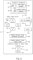
- FIG. 6 is a block diagram of an embodiment of a display 94 that may be employed within the user interface 92 of the harvester 10 of FIG. 5 . While the illustrated display 94 is described below with reference to the harvester 10, it should be appreciated that the same display or a similar display may be employed within the user interface 74 of the haul vehicle 30. As illustrated, the display 94 presents a graphical representation 184 of various controls that may be utilized to facilitate calibration of the conveyor outlet/storage compartment alignment, adjustment of the target point, and/or control of the unloading process. In the illustrated embodiment, the display 94 includes an alignment calibration screen 185.
- the alignment calibration screen 185 includes a graphical representation 186 of the bounding rectangle, a first indicator 187 representative of the first corner of the bounding rectangle, and a second indicator 188 representative of the second corner of the bounding rectangle.
- the alignment calibration screen 185 also includes a "first point aligned” button 189 and a "second point aligned” button 190.
- data associated with each previously calibrated storage compartment (e.g., data indicative of the positions of the first and second corners of the bounding rectangle and the position of the target point) is stored within the harvester control system. Accordingly, if a previously calibrated storage compartment is detected by the harvester control system, the alignment calibration screen 185 may be disabled (e.g., "grayed out”). However, if a new storage compartment is detected, the alignment calibration screen is enabled, thereby prompting the operator to initiate the calibration process. Once the calibration process is complete, the data associated with the new storage compartment is stored within the harvester control system for subsequent docking processes.
- the first indicator 187 illuminates, as illustrated, thereby prompting the operator (e.g., of the harvester or the haul vehicle) to align the conveyor outlet with the first desired point at the front left of the storage compartment. Once aligned, the operator depresses the "first point aligned" button 189. In certain embodiments, the operator is provided with an indication that the first desired point is accepted by the harvester control system (e.g., via a change in color of the first indicator 187, darkening the first indicator 187, etc.).
- the user interface may indicate a fault (e.g., via displaying a text message to the operator, changing the color of the first indicator 187, etc.). The operator may then realign the conveyor outlet with the first desired point.
- the second indicator 188 illuminates, thereby prompting the operator (e.g., of the harvester or the haul vehicle) to align the conveyor outlet with the second desired point at the rear right of the storage compartment. Once aligned, the operator depresses the "second point aligned" button 190. In certain embodiments, the operator is provided with an indication that the second desired point is accepted by the harvester control system (e.g., via a change of color of the second indicator 188, darkening the second indicator 188, etc.).
- the user interface may indicate a fault (e.g., via displaying a text message to the operator, changing the color of the second indicator 188, etc.). The operator may then realign the conveyor outlet with the second desired point and/or restart the calibration process.
- the harvester controller establishes the bounding rectangle having a first corner at the first desired point and a second corner at the second desired point.
- the harvester controller also establishes a target point at the center of the bounding rectangle.
- the position of the target point may be adjusted based on user input.
- the display 94 includes a target point offset screen having controls configured to adjust the position of the target point (e.g., away from the center of the bounding rectangle).
- the display includes a lateral position adjustment section 191 having a left arrow button 192, a right arrow button 193, and a numerical display 194.
- Depressing the left arrow button 192 induces the display 194 to indicate movement of the target point to the left (e.g., in inches relative to the original target point).
- depressing the right arrow button 193 induces the display 194 to indicate movement of the target point to the right (e.g., in inches relative to the original target point).
- the display 94 also includes a longitudinal position adjustment section 195 having a forward arrow button 196, a rearward arrow button 198, and a numerical display 200.
- Depressing the forward arrow button 196 induces the display 200 to indicate movement of the target point in the forward direction (e.g., in inches relative to the original target point).
- depressing the rearward arrow button 198 induces the display 200 to indicate movement of the target point in the rearward direction (e.g., in inches relative to the original target point).
- the illustrated displays 194 and 200 are configured to present the offset distances in inches, it should be appreciated that, in alternative embodiments, the offset distances may be expressed in terms of a percentage of the lateral and/or longitudinal extent of the bounding rectangle. In further embodiments, the displays 194 and 200 may present a graphical representation of the position of the target point within the bounding rectangle.
- the operator may depress the "set to current" button 202. Depressing the button 202 induces the user interface to send a signal to the harvester controller that instructs the controller to adjust the lateral and/or longitudinal position of the target point.
- the operator may periodically adjust the position of the target point during the unloading process to establish a substantially even distribution of agricultural product within the storage compartment.
- the operator may reset the target point to the original centered position by depressing the reset button 204.
- each adjustment of the target point may be relative to the original centered position of the target point.
- each adjustment to the target point may be relative to the previously selected target point position.
- the lateral and/or longitudinal position of the established target point may be adjusted.
- an operator may adjust the position of the established target point (e.g., relative to the bounding rectangle) via the target point offset controls or additional controls provided on the display 94.
- the updated position is stored within the harvester control system for subsequent docking processes. Accordingly, at least a first adjustment of the target point via the target point offset controls is relative to the updated position of the established target point.
- the positions of the first and second corners of the established bounding rectangle may be adjusted (e.g., via controls provided on the display 94) to create a bounding rectangle having a desired size and/or position.
- the display 94 includes an "engage product flow/bounding rectangle" button 206. Depressing the button 206 sends a signal to the harvester controller instructing the controller to automatically engage product flow from the conveyor outlet to the storage compartment while the conveyor outlet is within the bounding rectangle.
- the display 94 also includes an "engage product flow/target point” button 208. Depressing the button 208 sends a signal to the harvester controller instructing the controller to automatically engage product flow from the conveyor outlet to the storage compartment while the conveyor outlet is within a threshold range of the target point. In the illustrated embodiment, the threshold range may be adjusted by a "threshold range of target point" section 210 of the display 94.
- the section 210 includes a first arrow button 212 configured to increase the threshold range, a second arrow button 214 configured to decrease the threshold range, and a numeric display 216 configured to display the threshold range.
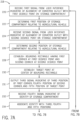
- FIG. 7 is a flow diagram of an embodiment of a method 218 for calibrating alignment of a conveyor outlet of an agricultural harvester with a storage compartment of an agricultural product transportation system.
- a first signal indicative of alignment of the conveyor outlet with a first desired point on the storage compartment is received from a user interface.
- a user interface For example, when the conveyor outlet is aligned with the first desired point on the storage compartment, an operator may depress a graphical representation of a "first point aligned" button on a display of the user interface.
- the user interface may output the first signal.
- a first position of the storage compartment relative to the agricultural vehicle is determined, as represented by block 222.
- a second signal indicative of alignment of the conveyor outlet with a second desired point on the storage compartment, diagonally opposite the first desired point, is received from the user interface.
- a second signal indicative of alignment of the conveyor outlet with a second desired point on the storage compartment, diagonally opposite the first desired point is received from the user interface.
- an operator may depress a graphical representation of a "second point aligned" button on a display of the user interface.
- the user interface may output the second signal.
- a second position of the storage compartment relative to the agricultural vehicle is determined, as represented by block 226.
- a bounding rectangle is established, as represented by block 228.
- the bounding rectangle has a first corner at the first desired point and a second corner at the second desired point.
- a target point is established at the center of the bounding rectangle. That is, the target point is established at the lateral midpoint between the first and second corners, and at the longitudinal midpoint between the first and second corners.
- a third signal indicative of a third position of the first corner of the bounding rectangle relative to the storage compartment, a fourth position of the second corner of the bounding rectangle relative to the storage compartment, and a fifth position of the target point relative to the storage compartment is output, as represented by block 231.
- the third signal may be transmitted to the haul vehicle, thereby enabling the haul vehicle controller to determine a target position that aligns the target point with the conveyor outlet.
- the third signal indicative of the third position, the fourth position, and the fifth position may include a position of the first corner of the bounding rectangle, a position of the second corner of the bounding rectangle, and a position of the target point relative to a fixed point on the storage compartment (e.g., the intersection of the lateral and longitudinal centerlines of the storage compartment).
- the third signal may include the first position of the storage compartment relative to the agricultural vehicle, which is indicative of the third position, and the second position of the storage compartment relative to the agricultural vehicle, which is indicative of the fourth position.
- the third position may be determined based on the first position and the offset between the agricultural vehicle (e.g., the intersection of the lateral centerline and the reference line of the agricultural vehicle) and the conveyor outlet
- the fourth position may be determined based on the second position and the offset between the agricultural vehicle and the conveyor outlet
- the fifth position may be determined based on the first position, the second position, and the offset between the agricultural vehicle and the conveyor outlet.
- a fourth signal indicative of an identity of the storage compartment is received (e.g., from the haul vehicle transceiver), as represented by block 232.
- the identity is associated with the third, fourth, and fifth positions, as represented by block 234.
- the dimensions of the bounding rectangle are then compared to a threshold range, as represented by block 236.
- the threshold range may be associated with a minimum and/or a maximum expected size of the storage compartment. If the dimensions of the bounding rectangle are within the threshold range, the identity of the storage compartment and the third, fourth, and fifth positions are stored for subsequent alignment of the conveyor outlet with the storage compartment, as represented by block 238.
- first position and the second position are also compared to a threshold range prior to storing the identity and the third, fourth, and fifth positions, thereby verifying that a desired spacing is established between the agricultural vehicle and the storage compartment.
- the fifth position of the target point may be laterally and/or longitudinally adjusted based on a fifth signal from the user interface, as represented by block 240.
- the user interface may include a display having a "target point offset" screen. This screen enables an operator to adjust the position of the target point via graphical representations of indicator arrows. Once the position of the target point is adjusted, the new target point may be transmitted to the haul vehicle controller, thereby facilitating alignment of the conveyor outlet with the new target point. By adjusting the target point during the unloading operation, agricultural product may be substantially evenly distributed throughout the storage compartment.
- the user interface may enable the operator to reset the target point to the initiation position, i.e., centered within the bounding rectangle.
- product flow from the conveyor outlet to the storage compartment may be automatically engaged while the conveyor outlet is within the bounding rectangle, as represented by block 242.
- the agricultural product may continue to flow even as movement of the harvester relative to the storage compartment (e.g., due to variations in the terrain) varies the position of the conveyor outlet within the bounding rectangle.
- product flow from the conveyor outlet to the storage compartment may be automatically engaged while the conveyor outlet is within a threshold range of the target point, as represented by block 242.
- the threshold range is adjustable via the user interface (e.g., based on expected movement of the harvester relative to the storage compartment).
- first determined position and the first determined velocity of the harvester, and the second determined position and the second determined velocity of the haul vehicle are determined with respect to a fixed coordinate system in the embodiments described herein, it should be appreciated that, in alternative embodiments, the first determined position, the first determined velocity, the second determined position, and/or the second determined velocity may be determined with respect to a moving coordinate system.
- first determined position and the first determined velocity of the harvester may be determined relative to the haul vehicle, thereby establishing a moving coordinate system having an origin at the haul vehicle.
- the second determined position and the second determined velocity of the haul vehicle may be determined relative to the harvester, thereby establishing a moving coordinate system having an origin at the harvester.
- control systems and methods are described herein with reference to an agricultural harvester and a mobile storage compartment (e.g., towed by a haul vehicle), it should be appreciated that the control systems and methods may be utilized for other agricultural and/or non-agricultural applications.
- the alignment calibration process described herein may be utilized to facilitate automatic alignment of a harvester with a stationary storage compartment.
- the automatic control systems and methods described herein may be employed to automatically dock the mobile storage compartment with an on-road transport vehicle, such as a commercial truck, thereby facilitating efficient transfer of the agricultural product to the transport vehicle.
- the automatic control systems and methods described herein may be utilized to automatically dock a haul vehicle (e.g., dump truck) with a mining vehicle, thereby enabling the mining vehicle to efficiency unload ore or other materials.
- a haul vehicle e.g., dump truck
Landscapes
- Engineering & Computer Science (AREA)
- Life Sciences & Earth Sciences (AREA)
- Environmental Sciences (AREA)
- Physics & Mathematics (AREA)
- General Physics & Mathematics (AREA)
- Automation & Control Theory (AREA)
- Aviation & Aerospace Engineering (AREA)
- Radar, Positioning & Navigation (AREA)
- Remote Sensing (AREA)
- Mechanical Engineering (AREA)
- Soil Sciences (AREA)
- Guiding Agricultural Machines (AREA)
Description
- The invention relates generally to a system and method for coordinated control of agricultural vehicles.
- A harvester may be used to harvest agricultural crops, such as cotton, wheat, flax, or other crops. Generally, components (e.g., drums, spindles, blades, etc.) of the harvester remove portions of the agricultural crops from the ground. The harvester then conveys the removed portions of the agricultural crops (e.g., agricultural products) to an internal storage compartment, either directly or via a processing device configured to remove undesirable portions of the agricultural products.
- As the harvester traverses a field, the volume of the agricultural product stored within the internal storage compartment increases. Accordingly, the internal storage compartment is typically unloaded multiple times during the harvesting process. One method of unloading the internal storage compartment, generally know as unloading on-the-go, involves periodically transferring the agricultural product to a mobile storage compartment while the harvester is in motion. The mobile storage compartment is towed by a haul vehicle to a position proximate to the harvester. The operator of the haul vehicle aligns the storage compartment with a conveyor outlet of the harvester and substantially matches the speed of the harvester. The harvester operator then initiates transfer of the agricultural product from the harvester to the mobile storage compartment, thereby unloading the internal storage compartment of the harvester. Once the harvester is unload, the haul vehicle operator directs the mobile storage compartment to a remote location for offloading. This process repeats throughout the harvesting process.
WO-A1-2012/110508 discloses a control system for an agricultural vehicle, comprising a first transceiver configured to receive a first signal from a second transceiver of a target vehicle, wherein the first signal is indicative of a first determined position and a first determined velocity of the target vehicle. - Highly skilled drivers typically operate the haul vehicles due to the complexity associated with aligning the mobile storage compartment with the harvester and matching the speed of the harvester. Employing such drivers may increase the costs associated with the harvesting process and/or may delay the harvesting process due to the limited availability of these drivers. Furthermore, employing less skilled drivers to operate the haul vehicles may result in agricultural product loss due to misalignment of the mobile storage compartment with the harvester and/or mismatched operating speeds. As a result, the efficiency of the harvesting process may be reduced.
- According to the invention, a control system for an agricultural vehicle is provided having the features of claim 1.
- In an embodiment, the control system preferably includes a spatial locating device mounted on the agricultural vehicle and configured to determine a second determined position and a second determined velocity of the agricultural vehicle. In addition, the control system includes an automated steering control system configured to control a direction of movement of the agricultural vehicle, and an automated speed control system configured to control a speed of the agricultural vehicle. The control system also includes a controller communicatively coupled to the first transceiver, to the spatial locating device, to the automated steering control system, and to the automated speed control system. The controller is configured to automatically control the agricultural vehicle by determining a target position and a target velocity of the agricultural vehicle based at least in part on the first determined position and the first determined velocity of the target vehicle, determining a route to the target position based at least in part on the target position, the second determined position, and the second determined velocity, instructing the automated steering control system and the automated speed control system to direct the agricultural vehicle toward the target position along the route, and instructing the automated steering control system and the automated speed control system to substantially maintain the target position and the target velocity upon substantially reaching the target position.
- In a further embodiment, a method for controlling an agricultural vehicle includes receiving a first signal indicative of a first determined position and a first determined velocity of a target vehicle. The method also includes determining a target position and a target velocity of the agricultural vehicle based at least in part on the first determined position and the first determined velocity of the target vehicle. In addition, the method includes instructing an automated steering control system and an automated speed control system to direct the agricultural vehicle toward the target position, and instructing the automated steering control system and the automated speed control system to substantially maintain the target position and the target velocity upon substantially reaching the target position.
- These and other features, aspects, and advantages of the present invention will become better understood when the following detailed description is read with reference to the accompanying drawings in which like characters represent like parts throughout the drawings, wherein:
-
FIG. 1 is a top view of an embodiment of an agricultural harvester and an agricultural product transportation system, in which the agricultural product transportation system is configured to automatically dock with the agricultural harvester; -
FIG. 2 is a schematic diagram of an embodiment of an agricultural harvester and a haul vehicle, which may be employed within the agricultural product transportation system ofFIG. 1 ; -
FIG. 3 is a state diagram of an embodiment of a technique for controlling a haul vehicle; -
FIG. 4 is a flow diagram of an embodiment of a method for controlling a haul vehicle; -
FIG. 5 is a schematic diagram of an embodiment of an agricultural harvester and an agricultural product transportation system; -
FIG. 6 is a block diagram of an embodiment of a display that may be employed within a user interface of the haul vehicle ofFIG. 5 ; and -
FIG. 7 is a flow diagram of an embodiment of a method for calibrating alignment of a conveyor outlet of an agricultural harvester with a storage compartment of an agricultural product transportation system. -
FIG. 1 is a top view of an embodiment of an agricultural harvester and an agricultural product transportation system, in which the agricultural product transportation system is configured to automatically dock with the agricultural harvester. In the illustrated embodiment, theagricultural harvester 10 includes a row ofharvesting units 12 positioned on a front end of achassis 14 and aninternal storage compartment 16 coupled to thechassis 14. As theagricultural harvester 10 traverses a field in a direction oftravel 18, theharvesting units 12 engageunharvested plants 20 and extract various agricultural products (e.g., corn, wheat, cotton, etc.) from the plants. These agricultural products are transferred to theinternal storage compartment 16, either directly or via a processing device configured to remove undesirable portions of the agricultural products. The remaining portions of the plants remain in the field asagricultural residue 22. - As the
harvester 10 traverses the field, the volume of the agricultural product stored within theinternal storage compartment 16 increases. Accordingly, theharvester 10 includes aconveyor 24 configured to transfer the agricultural product to a mobile storage compartment while the harvester is in motion. Theconveyor 24 may include an auger, a conveyor belt, or other suitable device configured to transfer the agricultural product from theinternal storage compartment 16 to anoutlet 26. As discussed in detail below, the mobile storage compartment may be automatically aligned with theconveyor outlet 26, thereby enhancing the efficiency of the harvester unloading process. While the illustratedagricultural harvester 10 is a self-propelled vehicle, it should be appreciated that, in certain embodiments, the agricultural harvester may be towed behind a tractor or other work vehicle. In addition, while the illustratedagricultural harvester 10 includes aninternal storage compartment 16, it should be appreciated that the internal storage compartment may be omitted in certain harvester configurations. In such configurations, the harvester may continuously transfer agricultural product to the mobile storage compartment as the harvester extracts and processes the agricultural products. - In the illustrated embodiment, an agricultural
product transportation system 28 is configured to receive the agricultural product from theharvester 10. As illustrated, theproduct transportation system 28 includes ahaul vehicle 30, such as the illustrated tractor, and a mobile storage compartment 32 (e.g., grain cart). As discussed in detail below, thehaul vehicle 30 includes a controller configured to automatically direct the storage compartment along aroute 34 to a target position adjacent to theharvester 10. That is, the controller may automatically control thehaul vehicle 10 during a docking process, thereby positioning the storage compartment in a location that enhances the transfer efficiency of the agricultural product from the harvester to the storage compartment. In certain embodiments, the controller is configured to determine a target position and a target velocity of the haul vehicle based at least in part on a determined position and a determined velocity of theharvester 10. The controller is also configured to instruct an automated steering control system and an automated speed control system to direct the haul vehicle toward the target position. Once the haul vehicle substantially reaches the target position, the controller is configured to instruct the automated steering control system and the automated speed control system to substantially maintain the target position and the target velocity. - In certain embodiments, the target position corresponds to a position that substantially aligns the
conveyor outlet 26 with a target point on thestorage compartment 32. Accordingly, with the haul vehicle located at the target position, the agricultural product may be transferred from theharvester 10 to thestorage compartment 32 while the vehicles are in motion. Because the controller automatically maintains the position of the storage compartment relative to the conveyor outlet during the unloading process, the possibility of agricultural product loss is substantially reduced or eliminated, thereby increasing the efficiency of the harvesting process. - By way of example, when the
haul vehicle 30 enters an area ofcommunication 36, communication is automatically established between a first transceiver on thehaul vehicle 30 and a second transceiver on theharvester 10. That is, the controller of the haul vehicle detects the harvester upon receiving a signal from the harvester transceiver, and the controller on the harvester detects the haul vehicle upon receiving a signal from the haul vehicle transceiver. As will be appreciated, arange 38 of the area ofcommunication 36 may be dependent on the broadcast power of the transceivers, the sensitivity of the transceivers, and/or the communication frequency, among other factors. In certain embodiments, each transceiver is configured to transmit data at a fixed interval (e.g., 50 Hz, 20 Hz, 10 Hz, 5 Hz, 1 Hz, 0.5 Hz, 0.1 Hz, etc.). As discussed in detail below, the data may include a position of the vehicle, a velocity of the vehicle, a steering angle of the vehicle, an orientation of the vehicle, and/or an identity of the vehicle, among other parameters. In addition, each transceiver may be configured to retransmit data received from another transceiver. For example, the haul vehicle closer to the harvester may receive a signal from the harvester, and then retransmit the signal to the haul vehicle farther from the harvester, thereby effectively extending the communication range of each transceiver. - To initiate the docking process, an operator of the haul vehicle provides input to a user interface, thereby instructing the controller to enable automatic control of the haul vehicle. If the haul vehicle is within an area of engagement 40 (i.e., a distance between the harvester and the haul vehicle is less than an engagement distance 42), the controller instructs the automated steering control system and the automated speed control system to direct the haul vehicle toward the target position. For example, if the harvester is positioned in front of the haul vehicle, the automated speed control system may increase the speed of the haul vehicle. Conversely, if the harvester is positioned behind the haul vehicle, the automated speed control system may stop the haul vehicle until the harvester reaches a docking position. In addition, the steering control system may adjust wheel angles, for example, to steer the haul vehicle toward the harvester. Once the haul vehicle substantially reaches the target position, the controller instructs the automated steering control system and the automated speed control system to substantially maintain the target position and the target velocity, thereby facilitating transfer of agricultural product from the harvester to the storage compartment.
-
FIG. 2 is a schematic diagram of an embodiment of anagricultural harvester 10 and ahaul vehicle 30, which may be employed within the agricultural product transportation system ofFIG. 1 . In the illustrated embodiment, thehaul vehicle 30 includes acontrol system 43 having a first transceiver 44 configured to receive a first signal from asecond transceiver 46 of a target vehicle, such as the illustratedagricultural harvester 10. As discussed in detail below, the first signal is indicative of a first determined position (e.g., three-dimensional position vector) and a first determined velocity (e.g., three-dimensional velocity vector) of theharvester 10. As will be appreciated, the first and second transceivers may operate at any suitable frequency range within the electromagnetic spectrum. For example, in certain embodiments, the transceivers may broadcast and receive radio waves within a frequency range of about 1 GHz to about 10 GHz. In addition, the first and second transceivers may utilize any suitable communication protocol, such as a standard protocol (e.g., Wi-Fi, Bluetooth, etc.) or a proprietary protocol. - As used herein, "position" (e.g., determined position, target position, etc.) refers to a position vector, such as a one, two, or three-dimensional position vector. For example, a two-dimensional position vector may include latitude and longitude, and a three-dimensional position vector may include latitude, longitude, and altitude/elevation. As will be appreciated, the position vector may be represented in a rectangular, polar, cylindrical, or spherical coordinate system, among other suitable coordinate systems. In addition, as used herein, "velocity" (e.g., determined velocity, target velocity, etc.) refers to a velocity vector, such as a one, two, or three-dimensional velocity vector. For example, a one-dimensional velocity vector may include speed (e.g., ground speed), a two-dimensional velocity vector may include speed (e.g., ground speed) and heading within a plane (e.g., along a ground plane), and a three-dimensional velocity vector may include speed and heading within a three-dimensional space. Similar to the position vector, the velocity vector may be represented in a rectangular, polar, cylindrical, or spherical coordinate system, among other suitable coordinate systems. In certain embodiments, the velocity may be represented as a unit/normalized vector, i.e., a vector having a unit magnitude. In such embodiments, the magnitude (e.g., speed) is not included in the velocity vector. For example, a two-dimensional velocity unit vector may be representative of heading within a plane (e.g., along a ground plane), and a three-dimensional velocity unit vector may be representative of heading within a three-dimensional space.
- The haul
vehicle control system 43 also includes aspatial locating device 48, which is mounted to thehaul vehicle 30 and configured to determine a second determined position and a second determined velocity of thehaul vehicle 30. As will be appreciated, the spatial locating device may include any suitable system configured to measure the position and velocity of the haul vehicle, such as a global positioning system (GPS), for example. In certain embodiments, thespatial locating device 48 may be configured to measure the position and velocity of the haul vehicle relative to a fixed point within a field (e.g., via a fixed radio transceiver). Accordingly, thespatial locating device 48 may be configured to measure the position and velocity of the haul vehicle relative to a fixed global coordinate system (e.g., via the GPS) or a fixed local coordinate system. In certain embodiments, the first transceiver 44 is configured to broadcast a second signal indicative of the second determined position and/or the second determined velocity to other vehicles within the area of communication. As discussed in detail below, the second signal from each haul vehicle may be utilized to determine which vehicle is closest to the harvester, thereby enabling the closest haul vehicle to dock with the harvester while the remaining vehicles wait for a subsequently unloading cycle. - In addition, the haul
vehicle control system 43 includes anorientation sensor 49 configured to determine a pitch angle, a yaw angle, and/or a roll angle of the haul vehicle. For example, theorientation senor 49 may include a gyroscope or other sensor configured to monitor the orientation of thehaul vehicle 30. In certain embodiments, theorientation sensor 49 is also configured to determine a pitch rate, a yaw rate, and/or a roll rate. Furthermore, in certain embodiments, the haulvehicle control system 43 is configured to compare the orientation (e.g., pitch angle, yaw angle, and/or roll angle) of thehaul vehicle 30 to a measured orientation (e.g., pitch angle, yaw angle, and/or roll angle) of theharvester 10 to establish a relative orientation that may be utilized to enhance the accuracy of the docking process. - In the illustrated embodiment, the
control system 43 includes an automatedsteering control system 50 configured to control a direction of movement of thehaul vehicle 30, and an automatedspeed control system 52 configured to control a speed of thehaul vehicle 30. In addition, thecontrol system 43 includes acontroller 56 communicatively coupled to the first transceiver 44, to thespatial locating device 48, to the automatedsteering control system 50, and to the automatedspeed control system 52. Thecontroller 56 is configured to automatically control thehaul vehicle 30 during docking and while docked with the harvester, thereby enhancing transfer efficiency of the agricultural product to the storage compartment. In certain embodiments, thecontroller 56 is configured to determine a target position and a target velocity of the haul vehicle based at least in part on the first determined position and the first determined velocity of the harvester. Thecontroller 56 is also configured to determine a route to the target position based at least in part on the target position, the second determined position of the haul vehicle, and the second determined velocity of the haul vehicle. Once the route is determined, the controller is configured to instruct the automated steering control system and the automated speed control system to direct the haul vehicle toward the target position along the route. Upon substantially reaching the target position, the controller is configured to instruct the automated steering control system and the automated speed control system to substantially maintain the target position and the target velocity. - Because the determined velocity of the harvester is utilized to determine the target position and the route to the target position, the control system described herein may be more efficient than control systems that utilize the position of the harvester alone to facilitate docking. For example, the haul vehicle control system may utilize the determined velocity of the harvester to determine an expected position of the harvester at the time of docking. Accordingly, the target position and the route to the target position may be determined based on the expected position instead of the instantaneous position. As a result, the efficiency of the docking process may be enhanced, thereby reducing the duration and costs associated with harvesting operations. As discussed in detail below, steering angle of the harvester, orientation of the harvester, heading of the harvester, and/or acceleration of the harvester may also be utilized to determine the target position and the route to the target position, thereby further enhancing the efficiency of the docking process.
- In certain embodiments, the target position is laterally and/or longitudinally offset relative to the harvester from the first determined position. For example, as discussed in detail below, a target point may be established on the storage compartment (e.g., at an approximate center point of the storage compartment). In such embodiments, the
haul vehicle controller 56 may determine a target position that substantially aligns the target point with the conveyor outlet of the harvester, thereby facilitating efficient transfer of agricultural product from the harvester to the storage compartment. - The
controller 56 is configured to determine a distance between the haul vehicle and the harvester based on the first determined position of the harvester and the second determined position of the haul vehicle. If the distance is less than or equal to the engagement distance, thecontroller 56 is configured to enable automatic control of the haul vehicle. Otherwise, the automatic control is disabled. In certain embodiments, upon detection of a separation distance less than or equal to the engagement distance, thecontroller 56 is configured to instruct a user interface to present an indication to an operator that automatic control is enabled. The operator may then initiate automatic control (e.g., via the user interface), thereby instructing the controller to direct the haul vehicle toward the target position. - In certain embodiments, the
controller 56 is an electronic controller having electrical circuitry configured to process data from the transceiver 44, thespatial locating device 48, and/or other components of thecontrol system 43. In the illustrated embodiment, thecontroller 56 include a processor, such as the illustratedmicroprocessor 58, and amemory device 60. Thecontroller 56 may also include one or more storage devices and/or other suitable components. Theprocessor 58 may be used to execute software, such as software for controlling thehaul vehicle 30, and so forth. Moreover, theprocessor 58 may include multiple microprocessors, one or more "general-purpose" microprocessors, one or more special-purpose microprocessors, and/or one or more application specific integrated circuits (ASICS), or some combination thereof. For example, theprocessor 58 may include one or more reduced instruction set (RISC) processors. - The
memory device 60 may include a volatile memory, such as random access memory (RAM), and/or a nonvolatile memory, such as ROM. Thememory device 60 may store a variety of information and may be used for various purposes. For example, thememory device 60 may store processor-executable instructions (e.g., firmware or software) for theprocessor 58 to execute, such as instructions for controlling thehaul vehicle 30. The storage device(s) (e.g., nonvolatile storage) may include read-only memory (ROM), flash memory, a hard drive, or any other suitable optical, magnetic, or solid-state storage medium, or a combination thereof. The storage device(s) may store data (e.g., position data, identification data, etc.), instructions (e.g., software or firmware for controlling the haul vehicle, etc.), and any other suitable data. - In the illustrated embodiment, the automated
steering control system 50 includes a wheelangle control system 62, adifferential braking system 64, and atorque vectoring system 66. The wheelangle control system 62 may automatically rotate one or more wheels of the haul vehicle (e.g., via hydraulic actuators) to steer the haul vehicle along a desired route. By way of example, the wheelangle control system 62 may rotate front wheels, rear wheels, and/or intermediate wheels of the haul vehicle, either individually or in groups. Thedifferential braking system 64 may independently vary the braking force on each lateral side of the haul vehicle to direct the haul vehicle along the desired route. Similarly, thetorque vectoring system 66 may differentially apply torque from an engine to wheels and/or tracks on each lateral side of the haul vehicle, thereby directing the haul vehicle along a desired route. While the illustratedsteering control system 50 includes the wheelangle control system 62, thedifferential braking system 64, and thetorque vectoring system 66, it should be appreciated that alternative embodiments may include one or two of these systems, in any suitable combination. Further embodiments may include an automatedsteering control system 50 having other and/or additional systems to facilitate directing the haul vehicle along the desired route. - In the illustrated embodiment, the automated
speed control system 52 includes an engineoutput control system 68, atransmission control system 70, and abraking control system 72. The engineoutput control system 68 is configured to vary the output of the engine to control the speed of the haul vehicle. For example, the engineoutput control system 68 may vary a throttle setting of the engine, a fuel/air mixture of the engine, a timing of the engine, and/or other suitable engine parameters to control engine output. In addition, thetransmission control system 70 may adjust gear selection within a transmission to control the speed of the haul vehicle. Furthermore, thebraking control system 72 may adjust braking force, thereby controlling the speed of thehaul vehicle 30. While the illustrated automatedspeed control system 52 includes the engineoutput control system 68, thetransmission control system 70, and thebraking control system 72, it should be appreciated that alternative embodiments may include one or two of these systems, in any suitable combination. Further embodiments may include an automatedspeed control system 52 having other and/or additional systems to facilitate adjusting the speed of the haul vehicle. - In the illustrated embodiment, the haul
vehicle control system 43 includes auser interface 74 communicatively coupled to thecontroller 56. Theuser interface 74 is configured to selectively instruct thecontroller 56 to automatically control the haul vehicle based on operator input. For example, the operator may position the haul vehicle within the area of engagement, and then activate the automatic docking process via input to theuser interface 74. In certain embodiments, the user interface includes adisplay 76 configured to present information to the operator, such as whether the haul vehicle is within the area of communication, whether the haul vehicle is within the area of engagement, and whether conditions for automatic docking have been satisfied, among other parameters. In addition, as discussed in detail below, theuser interface 74 may enable the operator to adjust the target point while the haul vehicle is docked with the harvester. - As illustrated, the
haul vehicle 30 includes manual controls 78 configured to enable an operator to control the haul vehicle while the automatic control system is disengaged. The manual controls 78 may include manual steering control, manual transmission control, and/or manual braking control, among other controls. In the illustrated embodiment, the manual controls 78 are communicatively coupled to thecontroller 56. Thecontroller 56 is configured to disengage automatic control of the haul vehicle upon receiving a signal indicative of manual control of the haul vehicle. Accordingly, if an operator controls the haul vehicle manually, the automatic docking/docked process terminates, thereby restoring control of the haul vehicle to the operator. - In the illustrated embodiment, the
harvester 10 includes acontrol system 79 having aspatial locating device 80, which is mounted to theharvester 10 and configured to determine the first determined position and the first determined velocity of theagricultural harvester 10. Similar to the haul vehiclespatial locating device 48, the harvesterspatial locating device 80 may include any suitable system configured to measure the position and velocity of the harvester, such as a global positioning system (GPS), for example. In certain embodiments, thespatial locating device 80 may be configured to measure the position and velocity of the harvester relative to a fixed point within a field (e.g., via a fixed radio transceiver). Accordingly, thespatial locating device 80 may be configured to measure the position and velocity of the harvester relative to a fixed global coordinate system (e.g., via the GPS) or a fixed local coordinate system. As illustrated, thespatial locating device 80 is communicatively coupled to acontroller 82 of theharvester control system 79. Similar to thehaul vehicle controller 56, theharvester controller 82 includes a processor, such as the illustratedmicroprocessor 84, and amemory device 86. Thecontroller 82 is communicatively coupled to thesecond transceiver 46 and configured to transmit position and velocity information from thespatial locating device 80 to thetransceiver 46, thereby generating the first signal indicative of the first determined position and the first determined velocity of theagricultural harvester 10. - In the illustrated embodiment, the
harvester control system 79 also includes asteering angle sensor 88 and anorientation sensor 90. Thesteering angle sensor 88 is configured to output a signal indicative of a measured and/or determined steering angle. For example, thesteering angle sensor 88 may be configured to measure an angle of certain wheels (e.g., front wheels, rear wheels, etc.) relative to the chassis of the harvester. Thesteering angle sensor 88 may also be configured to measure differential braking forces (e.g., the braking force applied to each lateral side of the harvester). In addition, thesteering angle sensor 88 may be configured to measure torque applied to each lateral side of the harvester (e.g., torque applied to a left wheel/track and torque applied to a right wheel/track). As illustrated, thesteering angle sensor 88 is communicatively coupled to thecontroller 82. Thecontroller 82 is configured to receive the signal indicative of steering angle from thesensor 88, and to transmit the signal to thetransceiver 46. Thetransceiver 46, in turn, is configured to incorporate the steering angle information into the first signal to the haul vehicle. The steering angle information may enable the haul vehicle control system to more accurately predict the expected position of the harvester, thereby enhancing the efficiency of the docking process. - Furthermore, the
orientation sensor 90 is configured to output a signal indicative of a measured pitch angle, a measured yaw angle, and/or a measured roll angle of the harvester. For example, theorientation senor 90 may include a gyroscope or other sensor configured to monitor the orientation of theharvester 10. In certain embodiments, theorientation sensor 90 is also configured to determine a pitch rate, a yaw rate, and/or a roll rate. As illustrated, theorientation sensor 90 is communicatively coupled to thecontroller 82. Thecontroller 82 is configured to receive the signal indicative of the orientation measurements from theorientation sensor 90, and to transmit the signal to thetransceiver 46. Thetransceiver 46, in turn, is configured to incorporate the orientation information into the first signal to the haul vehicle. The orientation information may enable the haul vehicle control system to more accurately predict the expected position of the harvester, thereby enhancing the efficiency of the docking process. - While the illustrated harvester control system includes a
steering angle sensor 88 and anorientation sensor 90, it should be appreciated that one or both of these sensors may be omitted in certain embodiments. In addition, it should be appreciated that the harvester may include additional sensors configured to measure other parameters associated with operation of the harvester. For example, in certain embodiments, the harvester control system may include an electronic compass configured to output a signal indicative of heading. In further embodiments, the harvester control system may include an accelerometer configured to output a signal indicative of acceleration (e.g., three-dimensional acceleration) of the harvester. The output from such sensors may be incorporated within the first signal to the haul vehicle. For example, in certain embodiments, the heading information may be incorporated within the first determined velocity. The heading and/or acceleration information may enable the haul vehicle control system to more accurately predict the expected position of the harvester, thereby enhancing the efficiency of the docking process. While an electronic compass and an accelerometer are described above, it should be appreciated that, in further embodiments, the harvester control system may include other and/or additional sensors. - In the illustrated embodiment, the
harvester control system 79 includes auser interface 92 configured to receive input from an operator of the agricultural vehicle. As discussed in detail below, theuser interface 92 includes adisplay 94 configured to present information to the harvester operator and/or to receive input from the operator. As illustrated, theuser interface 92 is communicatively coupled to thecontroller 82. In certain embodiments, thecontroller 82 is configured to calibrate alignment of the conveyor outlet of the harvester with a storage compartment coupled to the haul vehicle. In such embodiments, thecontroller 82 is configured to receive a first signal from theuser interface 92 indicative of alignment of the conveyor outlet with a first desired point on the storage compartment, and to determine a first position of the storage compartment relative to the agricultural harvester upon receiving the first signal. Thecontroller 82 is also configured to receive a second signal from theuser interface 92 indicative of alignment of the conveyor outlet with a second desired point on the storage compartment, diagonally opposite the first desired point, and to determine a second position of the storage compartment relative to the agricultural harvester upon receiving the second signal. In addition, thecontroller 82 is configured to establish a bounding rectangle having a first corner at the first desired point and a second corner at the second desired point based on the first and second positions, and to establish a target point at a center of the bounding rectangle. - In certain embodiments, the
controller 82 is configured to output a signal to thesecond transceiver 46 indicative of a position of the first corner of the bounding rectangle relative to the storage compartment, a position of the second corner of the bounding rectangle relative to the storage compartment, and a position of the target point relative to the storage compartment. Thetransceiver 46, in turn, is configured to incorporate data corresponding to these positions into the signal transmitted to the first transceiver 44. The haulvehicle control system 43 may utilize the positions of the first and second corners of the bounding rectangle and/or the position of the target point, in addition to the position and velocity of the harvester, to determine the target position and/or the target velocity of the haul vehicle. For example, the haulvehicle control system 43 may determine a target position that substantially aligns the target point with the conveyor outlet of the harvester. In addition, because thecontroller 82 outputs a signal indicative of the positions of the first and second corners of the bounding rectangle and the position of the target point upon completion of the calibration process, the haulvehicle control system 43 may detect a successful calibration upon receiving the signal. In certain embodiments, the haulvehicle control system 43 may not initiate the docking process until a successful calibration is detected. - In certain embodiments, the
controller 82 is configured to laterally and/or longitudinally adjust the position of the target point based on input from theuser interface 92. For example, an operator of the harvester may periodically adjust the target position during the unloading process, thereby establishing a substantially even distribution of agricultural product within the storage compartment. Upon adjustment of the target point position, the updated position is transmitted to the haul vehicle control system 43 (e.g., via the transceiver 46). Upon receiving the updated target point position, the haulvehicle control system 43 adjusts the target position such that the conveyor outlet is aligned with the adjusted target point. In certain embodiments, the operator of the haul vehicle may also adjust the position of the target point via theuser interface 74. In addition, the position of the target point may be limited to locations within the bounding rectangle, thereby substantially reducing or eliminating the possibility of product loss during the unloading process. - In the illustrated embodiment, the
agricultural harvester 10 includes a product deliversystem 96 configured to transfer agricultural product from the harvester to the storage compartment. As illustrated, the product deliversystem 96 is communicatively coupled to thecontroller 82. In certain embodiments, thecontroller 82 is configured to automatically engage product flow from the conveyor outlet to the storage compartment (e.g., via activation of the product deliver system 96) while the conveyor outlet is within the bounding rectangle. In further embodiments, thecontroller 82 is configured to automatically engage product flow from the conveyor outlet to the storage compartment (e.g., via activation of the product deliver system 96) while the conveyor outlet is within a threshold range of the target point. -
FIG. 3 is a state diagram of an embodiment of atechnique 98 for controlling a haul vehicle. Prior to initiating the docking process, the control system is in aninitialization state 100. As indicated by thearrow 102, booting the control system transitions the control system from theinitialization state 100 to an "off'state 104. Switching the control system on, as indicated by thearrow 106 transitions the control system from the "off'state 104 to a "safe" state 108. Conversely, switching the control system off, as indicated by thearrow 110, transitions the control system to the "off'state 104. If no faults are detected within the system, as indicated by thearrow 112, the control system transitions to a "ready to dock"state 114. While in the "ready to dock" state, if a fault is detected, as indicated by thearrow 116, the control system transitions to the "safe" state 108. In addition, switching the control system off, as indicated by thearrow 118, transitions the control system from the "ready to dock"state 114 to the "off'state 104. - While the control system is in the "ready to dock"
state 114, the user interface may provide an indication to the operator that the haul vehicle is ready to dock. When the operator initiates docking (e.g., via the user interface) and the harvester confirms initiation of the docking process, as indicated by thearrow 120, the control system transitions to a "docking"state 122. While in the "docking"state 122, the automated steering control system and the automated speed control system direct the haul vehicle toward the target position. If the operator controls the haul vehicle manually, as indicated by thearrow 124, the control system transitions to the "safe" state 108, thereby disengaging automatic control of the haul vehicle. In addition, if a fault is detected (e.g., communication loss, the haul vehicle is unable to reach the target position, a heading error is detected, a speed range is exceeded, etc.), as indicated by thearrow 126, the control system transitions to an "alarm"state 128. For example, the user interface may present the operator with a visual and/or audible indication that a fault is detected and/or the nature of the fault. As indicated by thearrow 130, the automatic control is disengaged, which transitions the control system to the "safe" state 108. However, if the automatic control is also switched off, as indicated by thearrow 131, the control system transitions to the "offstate 104. - After the haul vehicle reaches the target position for a predetermined time interval, as indicated by the
arrow 132, the control system transitions to the "docked"state 134. By way of example, the predetermined time interval may be about 1 second, about 2 seconds, about 3 seconds, about 4 seconds, or more. While in the "docked"state 134, the automated steering control system and the automated speed control system substantially maintain the target position and the target velocity. If the operator controls the haul vehicle manually, as indicated by thearrow 136, the control system transitions to the "safe" state 108, thereby disengaging automatic control of the haul vehicle. In addition, if a fault is detected (e.g., communication loss, the haul vehicle is unable to reach the target position, etc.), as indicated by thearrow 138, the control system transitions to an "alarm"state 128. For example, the user interface may present the operator with a visual and/or audible indication that a fault is detected and/or the nature of the fault. As indicated by thearrow 130, the automatic control is disengaged, which transitions the control system to the "safe" state 108. However, if the automatic control is also switched off, as indicated by thearrow 131, the control system transitions to the "off'state 104. -
FIG. 4 is a flow diagram of an embodiment of amethod 140 for controlling an agricultural vehicle, such as the haul vehicle. First, as represented byblock 142, a first signal indicative of a first determined position and a first determined velocity of a target vehicle (e.g., the agricultural harvester) is received. As previously discussed, the first signal may be transmitted from a second transceiver of the target vehicle and received by a first transceiver of the agricultural vehicle. The target vehicle is detected upon reception of the first signal, as represented byblock 144. In addition, a target position and a target velocity of the agricultural vehicle is determined based on the first determined position and the first determined velocity of the target vehicle, as represented byblock 146. In certain embodiments, a steering angle of the target vehicle, a pitch angle of the target vehicle, a roll angle of the target vehicle, and/or a yaw angle of the target vehicle, which may be included within the first signal, are also utilized to determine the target position and the target velocity of the agricultural vehicle. For example, as previously discussed, an expected position of the target vehicle at the time of docking may be determined based on the velocity, steering angle, and/or orientation of the target vehicle. Accordingly, the target position may be determined based on the expected position instead of the instantaneous position. - Next, as represented by
block 148, a distance between the agricultural vehicle and the target vehicle is determined. The distance is then compared to an engagement distance, as represented byblock 150. If the distance is less than or equal to the engagement distance, automatic control of the agricultural vehicle is enabled. Upon initiation of automatic control by an operator, as represented byblock 151, an automated steering control system and an automated speed control system are instructed to direct the agricultural vehicle toward the target position, as represented byblock 152. For example, if the target vehicle is positioned in front of the agricultural vehicle, the automated speed control system may increase the speed of the agricultural vehicle. Conversely, if the target vehicle is positioned behind the agricultural vehicle, the automated speed control system may stop the agricultural vehicle until the target vehicle reaches a docking position. In addition, the steering control system may adjust wheel angles, for example, to steer the agricultural vehicle toward the target position. - The position of the agricultural vehicle is then compared to the target position, as represented by
block 154. If the target position is reached, the automated steering control system and the automated speed control system are instructed to maintain the target position and the target velocity, as represented byblock 156. For example, if the speed of the target vehicle increases, the automated speed control system may increase the speed of the agricultural vehicle to match the speed of the target vehicle. Similarly, if the target vehicle initiates a turn, the automated steering control system may direct the agricultural vehicle to match the movement of the target vehicle. As a result, alignment between the conveyor outlet and the storage compartment may be maintained throughout the unloading process, thereby substantially reducing or eliminating agricultural product loss and/or increasing the efficiency of the unloading process. - As represented by
block 158, a second signal indicative of a second determined position and a second determined velocity of the agricultural vehicle is broadcast to other agricultural vehicles within the area of communication. Other agricultural vehicles may utilize this information to determine which vehicle is closest to the target vehicle. For example, if multiple agricultural vehicles are within the area of engagement, each vehicle may compare its position, and the position of the other vehicles, to the position of the target vehicle. The control system of the vehicle closest to the target vehicle transitions to the "docking" state, while the control systems of the farther vehicles remain in a "ready to dock" state. In this manner, the closest vehicle docks with the target vehicle, while the remaining vehicles wait for a subsequent unloading cycle. -
FIG. 5 is a schematic diagram of an embodiment of anagricultural harvester 10 and an agriculturalproduct transportation system 28. In certain embodiments, the harvester controller is configured to calibrate alignment of theconveyor outlet 26 with thestorage compartment 32, thereby enabling the haul vehicle controller to establish a target position that facilitates efficient transfer of the agricultural product from the harvester to the storage compartment. In such embodiments, the harvester controller is configured to receive a first signal from a user interface indicative of alignment of theconveyor outlet 26 with a first desiredpoint 160 on thestorage compartment 32. For example, an operator of thehaul vehicle 30 may position the storage compartment 32 (e.g., via manual control of the haul vehicle) such that theconveyor outlet 26 is aligned with the first desiredpoint 160 at a front left portion of thestorage compartment 32, as illustrated by theharvester 10 in solid lines. Alternatively, an operator of theharvester 10 may position the harvester 10 (e.g., via manual control of the harvester) such that theconveyor outlet 26 is aligned with the first desiredpoint 160. Once aligned, the operator of theharvester 10 or the operator of thehaul vehicle 30 depresses a button on the user interface that transmits the first signal indicative of alignment to the harvester controller. - Upon receiving the first signal, the harvester controller determines a first position of the
storage compartment 32 relative to theharvester 10. In the illustrated embodiment, the first position includes alateral distance 162 that extends between alateral centerline 164 of thestorage compartment 32 and alateral centerline 166 of theharvester 10. The first position also includes alongitudinal distance 168 that extends between alongitudinal centerline 170 of thestorage compartment 32 and areference line 172 of theharvester 10. However, it should be appreciated that the position of thestorage compartment 32 relative to theharvester 10 may include lateral and longitudinal distances based on other suitable reference lines. - The harvester controller is also configured to receive a second signal from the user interface indicative of alignment of the
conveyor outlet 26 with a second desiredpoint 174 on thestorage compartment 32, diagonally opposite the first desiredpoint 160. For example, an operator of thehaul vehicle 30 may position the storage compartment 32 (e.g., via manual control of the haul vehicle) such that theconveyor outlet 26 is aligned with the second desiredpoint 174 at a rear right portion of thestorage compartment 32, as illustrated by theharvester 10 in phantom lines. Alternatively, an operator of theharvester 10 may position the harvester 10 (e.g., via manual control of the harvester) such that theconveyor outlet 26 is aligned with the second desiredpoint 174. Once aligned, the operator of theharvester 10 or the operator of thehaul vehicle 30 depresses a button on the user interface that transmits the second signal indicative of alignment to the harvester controller. - Upon receiving the second signal, the harvester controller determines a second position of the
storage compartment 32 relative to theharvester 10. In the illustrated embodiment, the second position includes alateral distance 176 that extends between thelateral centerline 164 of thestorage compartment 32 and thelateral centerline 166 of theharvester 10. The second position also includes alongitudinal distance 178 that extends between thelongitudinal centerline 170 of thestorage compartment 32 and thereference line 172 of theharvester 10. As noted above, it should be appreciated that the position of thestorage compartment 32 relative to theharvester 10 may include lateral and longitudinal distances based on other suitable reference lines. However, the first and second positions utilize the same references lines/coordinate system. - The harvester controller is also configured to establish a bounding
rectangle 180 having a first corner at the first desiredpoint 160 and a second corner at the second desiredpoint 174 based on the first position and the second position of thestorage compartment 32 relative to theharvester 10. In certain embodiments, the harvester controller may enable and/or automatically engage product flow from theconveyor outlet 26 to thestorage compartment 32 while theconveyor outlet 26 is within the boundingrectangle 180. Conversely, the harvester controller may disable and/or automatically disengage product flow from theconveyor outlet 26 to thestorage compartment 32 while theconveyor outlet 26 is outside of the boundingrectangle 180. While the illustratedbounding rectangle 180 is established based on the front left point and the rear right point, it should be appreciated that the bounding rectangle may also be established based on a front right point and a rear left point. - In addition, the harvester controller is configured to establish a
target point 182 at the center of the boundingrectangle 180. That is, thetarget point 182 is positioned at the lateral midpoint and the longitudinal midpoint of the boundingrectangle 180. In certain embodiments, the harvester controller is configured to automatically engage product flow from theconveyor outlet 26 to thestorage compartment 32 while theconveyor outlet 26 is within a threshold range of thetarget point 182. As discussed in detail below, the threshold range may be manually adjusted via a user interface. In addition, the harvester controller may be configured to adjust a lateral position and/or a longitudinal position of the target point (e.g., away from the center of the bounding rectangle) based on a signal from the user interface. For example, an operator may adjust the position of the target point via the user interface during the unloading process, thereby facilitating substantially even distribution of the agricultural product within thestorage compartment 32. However, the controller may limit the adjustment of the target point to locations within the bounding rectangle, thereby substantially reducing or eliminating the possibility of product loss during the unloading process. - In certain embodiments, the harvester controller is configured to store data indicative of the position of the first corner of the bounding rectangle relative to the storage compartment, the position of the second corner of the bounding rectangle relative to the storage compartment, and the position of the target point relative to the storage compartment (e.g., within the memory device of the controller) to facilitate subsequent alignment of the
conveyor outlet 26 with thestorage compartment 32. For example, the harvester controller may receive a signal indicative of an identity of the storage compartment 32 (e.g., a unique identification number). If such a signal is received, the harvester controller associates the identity of the storage compartment with the data indicative of the positions of the first and second corners of the bounding rectangle and the position of the target point. The harvester controller then stores these positions and the identity, thereby facilitating subsequent alignment of theconveyor outlet 26 with thestorage compartment 32. - In certain embodiments, the harvester controller is configured to determine whether the dimensions of the bounding
rectangle 180 are within a threshold range prior to storing the identity, and the data indicative of the positions of the first and second corners of the bounding rectangle and the position of the target point. For example, if the bounding rectangle is smaller than a minimum expected size or larger than a maximum expected size, the controller may instruct the operator (e.g., via the user interface) to recalibrate the alignment of the conveyor outlet and the storage compartment. In addition, the harvester controller may be configured to determine whether the first position and the second position of the storage compartment relative to the harvester are within a threshold range prior to storing the identity, and the data indicative of the positions of the first and second corners of the bounding rectangle and the position of the target point. For example, if the storage compartment is closer than a minimum desired separation distance or farther than a maximum desired separation distance, the controller may instruct the operator (e.g., via the user interface) to recalibrate the alignment of the conveyor outlet and the storage compartment. Once the calibration process is complete, the harvester control system may send a signal to the haul vehicle control system indicative of a successful calibration, thereby enabling the haul vehicle control system to initiate docking with the harvester. -
FIG. 6 is a block diagram of an embodiment of adisplay 94 that may be employed within theuser interface 92 of theharvester 10 ofFIG. 5 . While the illustrateddisplay 94 is described below with reference to theharvester 10, it should be appreciated that the same display or a similar display may be employed within theuser interface 74 of thehaul vehicle 30. As illustrated, thedisplay 94 presents agraphical representation 184 of various controls that may be utilized to facilitate calibration of the conveyor outlet/storage compartment alignment, adjustment of the target point, and/or control of the unloading process. In the illustrated embodiment, thedisplay 94 includes analignment calibration screen 185. Thealignment calibration screen 185 includes agraphical representation 186 of the bounding rectangle, afirst indicator 187 representative of the first corner of the bounding rectangle, and asecond indicator 188 representative of the second corner of the bounding rectangle. Thealignment calibration screen 185 also includes a "first point aligned"button 189 and a "second point aligned"button 190. - As previously discussed, data associated with each previously calibrated storage compartment (e.g., data indicative of the positions of the first and second corners of the bounding rectangle and the position of the target point) is stored within the harvester control system. Accordingly, if a previously calibrated storage compartment is detected by the harvester control system, the
alignment calibration screen 185 may be disabled (e.g., "grayed out"). However, if a new storage compartment is detected, the alignment calibration screen is enabled, thereby prompting the operator to initiate the calibration process. Once the calibration process is complete, the data associated with the new storage compartment is stored within the harvester control system for subsequent docking processes. - During the calibration process, the
first indicator 187 illuminates, as illustrated, thereby prompting the operator (e.g., of the harvester or the haul vehicle) to align the conveyor outlet with the first desired point at the front left of the storage compartment. Once aligned, the operator depresses the "first point aligned"button 189. In certain embodiments, the operator is provided with an indication that the first desired point is accepted by the harvester control system (e.g., via a change in color of thefirst indicator 187, darkening thefirst indicator 187, etc.). However, if the first desired point is not accepted by the harvester controller (e.g., because the distance between the haul vehicle/storage compartment and the harvester is less than a minimum threshold distance or greater than a maximum threshold distance), the user interface may indicate a fault (e.g., via displaying a text message to the operator, changing the color of thefirst indicator 187, etc.). The operator may then realign the conveyor outlet with the first desired point. - Once the harvester controller accepts the first desired point, the
second indicator 188 illuminates, thereby prompting the operator (e.g., of the harvester or the haul vehicle) to align the conveyor outlet with the second desired point at the rear right of the storage compartment. Once aligned, the operator depresses the "second point aligned"button 190. In certain embodiments, the operator is provided with an indication that the second desired point is accepted by the harvester control system (e.g., via a change of color of thesecond indicator 188, darkening thesecond indicator 188, etc.). However, if the second desired point is not accepted by the harvester controller (e.g., because the distance between the haul vehicle/storage compartment and the harvester is less than a minimum threshold distance or greater than a maximum threshold distance, or the dimensions of the bounding rectangle are larger or smaller than an expected range, etc.), the user interface may indicate a fault (e.g., via displaying a text message to the operator, changing the color of thesecond indicator 188, etc.). The operator may then realign the conveyor outlet with the second desired point and/or restart the calibration process. - Once the operator has aligned the conveyor outlet with the first and second desired points, the harvester controller establishes the bounding rectangle having a first corner at the first desired point and a second corner at the second desired point. The harvester controller also establishes a target point at the center of the bounding rectangle. As previously discussed, the position of the target point may be adjusted based on user input. In the illustrated embodiment, the
display 94 includes a target point offset screen having controls configured to adjust the position of the target point (e.g., away from the center of the bounding rectangle). As illustrated, the display includes a lateralposition adjustment section 191 having aleft arrow button 192, aright arrow button 193, and anumerical display 194. Depressing theleft arrow button 192 induces thedisplay 194 to indicate movement of the target point to the left (e.g., in inches relative to the original target point). Similarly, depressing theright arrow button 193 induces thedisplay 194 to indicate movement of the target point to the right (e.g., in inches relative to the original target point). - The
display 94 also includes a longitudinalposition adjustment section 195 having aforward arrow button 196, arearward arrow button 198, and anumerical display 200. Depressing theforward arrow button 196 induces thedisplay 200 to indicate movement of the target point in the forward direction (e.g., in inches relative to the original target point). Similarly, depressing therearward arrow button 198 induces thedisplay 200 to indicate movement of the target point in the rearward direction (e.g., in inches relative to the original target point). While the illustrateddisplays displays - Once the desired position of the target point is selected, the operator may depress the "set to current"
button 202. Depressing thebutton 202 induces the user interface to send a signal to the harvester controller that instructs the controller to adjust the lateral and/or longitudinal position of the target point. By way of example, the operator may periodically adjust the position of the target point during the unloading process to establish a substantially even distribution of agricultural product within the storage compartment. The operator may reset the target point to the original centered position by depressing thereset button 204. In certain embodiments, each adjustment of the target point may be relative to the original centered position of the target point. Alternatively, each adjustment to the target point may be relative to the previously selected target point position. - In certain embodiments, the lateral and/or longitudinal position of the established target point (e.g., the target point established by the alignment calibration process) may be adjusted. For example, an operator may adjust the position of the established target point (e.g., relative to the bounding rectangle) via the target point offset controls or additional controls provided on the
display 94. Once the position of the established target point is adjusted, the updated position is stored within the harvester control system for subsequent docking processes. Accordingly, at least a first adjustment of the target point via the target point offset controls is relative to the updated position of the established target point. In further embodiments, the positions of the first and second corners of the established bounding rectangle may be adjusted (e.g., via controls provided on the display 94) to create a bounding rectangle having a desired size and/or position. - In the illustrated embodiment, the
display 94 includes an "engage product flow/bounding rectangle" button 206. Depressing the button 206 sends a signal to the harvester controller instructing the controller to automatically engage product flow from the conveyor outlet to the storage compartment while the conveyor outlet is within the bounding rectangle. Thedisplay 94 also includes an "engage product flow/target point"button 208. Depressing thebutton 208 sends a signal to the harvester controller instructing the controller to automatically engage product flow from the conveyor outlet to the storage compartment while the conveyor outlet is within a threshold range of the target point. In the illustrated embodiment, the threshold range may be adjusted by a "threshold range of target point"section 210 of thedisplay 94. As illustrated, thesection 210 includes afirst arrow button 212 configured to increase the threshold range, asecond arrow button 214 configured to decrease the threshold range, and anumeric display 216 configured to display the threshold range. Once the threshold range is input and thebutton 208 is depressed, product flows to the storage compartment while the conveyor outlet is within the threshold range of the target point. Furthermore, in certain embodiments, the harvester controller may automatically disengage the product flow while the conveyor outlet is positioned outside of the bounding rectangle. -
FIG. 7 is a flow diagram of an embodiment of amethod 218 for calibrating alignment of a conveyor outlet of an agricultural harvester with a storage compartment of an agricultural product transportation system. First, as represented byblock 220, a first signal indicative of alignment of the conveyor outlet with a first desired point on the storage compartment is received from a user interface. For example, when the conveyor outlet is aligned with the first desired point on the storage compartment, an operator may depress a graphical representation of a "first point aligned" button on a display of the user interface. The user interface, in turn, may output the first signal. Upon receiving the first signal, a first position of the storage compartment relative to the agricultural vehicle is determined, as represented byblock 222. - Next, as represented by
block 224, a second signal indicative of alignment of the conveyor outlet with a second desired point on the storage compartment, diagonally opposite the first desired point, is received from the user interface. For example, when the conveyor outlet is aligned with the second desired point on the storage compartment, an operator may depress a graphical representation of a "second point aligned" button on a display of the user interface. The user interface, in turn, may output the second signal. Upon receiving the second signal, a second position of the storage compartment relative to the agricultural vehicle is determined, as represented byblock 226. - Once the first and second positions of the storage compartment relative to the agricultural vehicle are determined, a bounding rectangle is established, as represented by
block 228. The bounding rectangle has a first corner at the first desired point and a second corner at the second desired point. In addition, as represented byblock 230, a target point is established at the center of the bounding rectangle. That is, the target point is established at the lateral midpoint between the first and second corners, and at the longitudinal midpoint between the first and second corners. Once the bounding rectangle and the target point are established, a third signal indicative of a third position of the first corner of the bounding rectangle relative to the storage compartment, a fourth position of the second corner of the bounding rectangle relative to the storage compartment, and a fifth position of the target point relative to the storage compartment is output, as represented byblock 231. As previously discussed, the third signal may be transmitted to the haul vehicle, thereby enabling the haul vehicle controller to determine a target position that aligns the target point with the conveyor outlet. - It should be appreciated that the third signal indicative of the third position, the fourth position, and the fifth position may include a position of the first corner of the bounding rectangle, a position of the second corner of the bounding rectangle, and a position of the target point relative to a fixed point on the storage compartment (e.g., the intersection of the lateral and longitudinal centerlines of the storage compartment). Alternatively, the third signal may include the first position of the storage compartment relative to the agricultural vehicle, which is indicative of the third position, and the second position of the storage compartment relative to the agricultural vehicle, which is indicative of the fourth position. For example, the third position may be determined based on the first position and the offset between the agricultural vehicle (e.g., the intersection of the lateral centerline and the reference line of the agricultural vehicle) and the conveyor outlet, and the fourth position may be determined based on the second position and the offset between the agricultural vehicle and the conveyor outlet. In addition, the fifth position may be determined based on the first position, the second position, and the offset between the agricultural vehicle and the conveyor outlet.
- In certain embodiments, a fourth signal indicative of an identity of the storage compartment is received (e.g., from the haul vehicle transceiver), as represented by
block 232. In such embodiments, the identity is associated with the third, fourth, and fifth positions, as represented byblock 234. The dimensions of the bounding rectangle are then compared to a threshold range, as represented byblock 236. As previously discussed, the threshold range may be associated with a minimum and/or a maximum expected size of the storage compartment. If the dimensions of the bounding rectangle are within the threshold range, the identity of the storage compartment and the third, fourth, and fifth positions are stored for subsequent alignment of the conveyor outlet with the storage compartment, as represented byblock 238. Accordingly, once the calibration process is complete, subsequent docking of the storage compartment with the agricultural harvester may be initiated without performing additional calibration procedures. In certain embodiments, the first position and the second position are also compared to a threshold range prior to storing the identity and the third, fourth, and fifth positions, thereby verifying that a desired spacing is established between the agricultural vehicle and the storage compartment. - In the illustrated embodiment, the fifth position of the target point may be laterally and/or longitudinally adjusted based on a fifth signal from the user interface, as represented by
block 240. As previously discussed, the user interface may include a display having a "target point offset" screen. This screen enables an operator to adjust the position of the target point via graphical representations of indicator arrows. Once the position of the target point is adjusted, the new target point may be transmitted to the haul vehicle controller, thereby facilitating alignment of the conveyor outlet with the new target point. By adjusting the target point during the unloading operation, agricultural product may be substantially evenly distributed throughout the storage compartment. In addition, the user interface may enable the operator to reset the target point to the initiation position, i.e., centered within the bounding rectangle. - In certain embodiments, product flow from the conveyor outlet to the storage compartment may be automatically engaged while the conveyor outlet is within the bounding rectangle, as represented by
block 242. In such embodiments, the agricultural product may continue to flow even as movement of the harvester relative to the storage compartment (e.g., due to variations in the terrain) varies the position of the conveyor outlet within the bounding rectangle. However, if the conveyor outlet moves to a position outside of the bounding rectangle, product flow is automatically terminated, thereby substantially reducing or eliminating product loss. In further embodiments, product flow from the conveyor outlet to the storage compartment may be automatically engaged while the conveyor outlet is within a threshold range of the target point, as represented byblock 242. As previously discussed, the threshold range is adjustable via the user interface (e.g., based on expected movement of the harvester relative to the storage compartment). - While the first determined position and the first determined velocity of the harvester, and the second determined position and the second determined velocity of the haul vehicle are determined with respect to a fixed coordinate system in the embodiments described herein, it should be appreciated that, in alternative embodiments, the first determined position, the first determined velocity, the second determined position, and/or the second determined velocity may be determined with respect to a moving coordinate system. For example, in certain embodiments, the first determined position and the first determined velocity of the harvester may be determined relative to the haul vehicle, thereby establishing a moving coordinate system having an origin at the haul vehicle. In further embodiments, the second determined position and the second determined velocity of the haul vehicle may be determined relative to the harvester, thereby establishing a moving coordinate system having an origin at the harvester.
- Furthermore, while the control systems and methods are described herein with reference to an agricultural harvester and a mobile storage compartment (e.g., towed by a haul vehicle), it should be appreciated that the control systems and methods may be utilized for other agricultural and/or non-agricultural applications. For example, the alignment calibration process described herein may be utilized to facilitate automatic alignment of a harvester with a stationary storage compartment. In addition, the automatic control systems and methods described herein may be employed to automatically dock the mobile storage compartment with an on-road transport vehicle, such as a commercial truck, thereby facilitating efficient transfer of the agricultural product to the transport vehicle. Moreover, the automatic control systems and methods described herein may be utilized to automatically dock a haul vehicle (e.g., dump truck) with a mining vehicle, thereby enabling the mining vehicle to efficiency unload ore or other materials.
Claims (12)
- A control system (43) for an agricultural vehicle (30), comprising:a first transceiver (44) configured to receive a first signal from a second transceiver (46) of a target vehicle (10), wherein the first signal is indicative of a first determined position and a first determined velocity of the target vehicle (10); andcharacterized in that the system further comprising:
a controller (56) communicatively coupled to the first transceiver (44), wherein the controller (56) is configured to automatically control the agricultural vehicle (30) by determining a target position and a target velocity of the agricultural vehicle (30) based at least in part on the first determined position and the first determined velocity of the target vehicle (10), said controller (56) configured to determine a distance between the agricultural vehicle (30) and the target vehicle (10) based on the first determined position of the target vehicle (10) and a second determined position of the agricultural vehicle (30) and further configured for enabling the automatically control of the agricultural vehicle (30) if said determined distance is less than or equal to an engagement distance (42), and configured for instructing an automated steering control system (50) and an automated speed control system (52) to direct the agricultural vehicle (30) along a route (34) toward the target position and instructing the automated steering control system (50) and the automated speed control system (52) to substantially maintain the target position and the target velocity upon substantially reaching the target position. - The control system (43) of claim 1, wherein the target position is laterally offset from the first determined position, longitudinally offset from the first determined position, or a combination thereof, relative to the target vehicle (10), and the target velocity is substantially equal to the first determined velocity.
- The control system (43) of claim 1, wherein the controller (56) is configured to detect the target vehicle (10) upon reception of the first signal by the first transceiver (44).
- The control system (43) of claim 1, wherein the first transceiver (44) is configured to broadcast the first signal to other vehicles.
- The control system (43) of claim 1, wherein the first signal comprises a steering angle of the target vehicle (10), a pitch angle of the target vehicle (10), a roll angle of the target vehicle (10), a yaw angle of the target vehicle (10), or a combination thereof, and the controller (56) is configured to adjust the target position based on the steering angle of the target vehicle (10), the pitch angle of the target vehicle (10), the roll angle of the target vehicle (10), the yaw angle of the target vehicle (10), or the combination thereof.
- The control system (43) of claim 1, wherein the controller (56) is configured to determine a distance between the agricultural vehicle (30) and the target vehicle (10), and to automatically control the agricultural vehicle (30) while the distance is less than or equal to an engagement distance.
- The control system (43) of claim 1, comprising a user interface (74) communicatively coupled to the controller (56), wherein the user interface (74) is configured to selectively instruct the controller (56) to automatically control the agricultural vehicle (30) based on operator input.
- The control system (43) of claim 7, wherein the controller (56) is configured to adjust the target position based on input from the user interface (74).
- The control system (43) of claim 1, wherein the controller (56) is configured to disengage automatic control of the agricultural vehicle (30) upon receiving a third signal indicative of manual control (78) of the agricultural vehicle (30).
- The control system (43) of claim 1, wherein the transceiver (44) is configured to broadcast a second signal indicative of a second determined position of the agricultural vehicle (30), a second determined velocity of the agricultural vehicle (30), or a combination thereof.
- The control system (43) of claim 1, further comprising:a spatial locating device (48) mounted on the agricultural vehicle (30) and configured to determine a second determined position and a second determined velocity of the agricultural vehicle (30);the automated steering control system (50) configured to control a direction of movement of the agricultural vehicle (30); andthe automated speed control system (52) configured to control a speed of the agricultural vehicle (30);wherein the controller (56) is further configured to determine a route to the target position based at least in part on the target position, the second determined position, and the second determined velocity, instructing the automated steering control system (50) and the automated speed control system (52) to direct the agricultural vehicle (30) toward the target position along the route.
- The control system (43) of claim 11, wherein the automated steering control system (50) comprises a wheel angle control system (62), a differential braking system (64), a torque vectoring system (66), or a combination thereof, and the automated speed control system (52) comprises an engine output control system (68), a transmission control system (70), a braking control system (72), or a combination thereof.
Applications Claiming Priority (1)
| Application Number | Priority Date | Filing Date | Title |
|---|---|---|---|
| US201462011991P | 2014-06-13 | 2014-06-13 |
Publications (3)
| Publication Number | Publication Date |
|---|---|
| EP2954769A1 EP2954769A1 (en) | 2015-12-16 |
| EP2954769B1 EP2954769B1 (en) | 2017-12-06 |
| EP2954769B2 true EP2954769B2 (en) | 2023-05-10 |
Family
ID=53434235
Family Applications (1)
| Application Number | Title | Priority Date | Filing Date |
|---|---|---|---|
| EP15171799.8A Active EP2954769B2 (en) | 2014-06-13 | 2015-06-12 | System and method for coordinated control of agricultural vehicle |
Country Status (3)
| Country | Link |
|---|---|
| US (1) | US9915952B2 (en) |
| EP (1) | EP2954769B2 (en) |
| BR (1) | BR102015013228B1 (en) |
Families Citing this family (73)
| Publication number | Priority date | Publication date | Assignee | Title |
|---|---|---|---|---|
| WO2015006609A1 (en) * | 2013-07-10 | 2015-01-15 | Agco Coporation | Automation of networking a group of machines |
| WO2015006600A1 (en) * | 2013-07-10 | 2015-01-15 | Agco Corporation | Automating distribution of work in a field |
| BE1022142B1 (en) * | 2014-05-15 | 2016-02-19 | Cnh Industrial Belgium Nv | METHOD FOR HARVESTING M.B.V. UNMANNED WORK VEHICLES FOR AGRICULTURE. |
| BR102016024930B1 (en) * | 2016-01-06 | 2021-08-24 | Cnh Industrial America Llc | CONTROL SYSTEM FOR A TOW VEHICLE AND METHOD FOR CONTROLLING AN AGRICULTURAL VEHICLE |
| US10152891B2 (en) * | 2016-05-02 | 2018-12-11 | Cnh Industrial America Llc | System for avoiding collisions between autonomous vehicles conducting agricultural operations |
| BR112018074104B1 (en) * | 2016-05-24 | 2022-04-12 | Cnh Industrial America Llc | System and method for replenishing a resource in an agricultural system |
| US10589626B2 (en) * | 2016-06-20 | 2020-03-17 | Caterpillar Inc. | Implement positioning guidance system |
| US10269242B2 (en) * | 2016-07-12 | 2019-04-23 | Ford Global Technologies, Llc | Autonomous police vehicle |
| US20180022559A1 (en) * | 2016-07-22 | 2018-01-25 | Scott William Knutson | Loader Positioning System |
| CN106263256B (en) | 2016-08-08 | 2018-07-06 | 浙江吉利控股集团有限公司 | Shock-absorbing sole structure with aerification function |
| EP3509800A4 (en) | 2016-09-06 | 2019-09-18 | Advanced Intelligent Systems Inc. | Mobile work station for transporting a plurality of articles |
| US10480157B2 (en) * | 2016-09-07 | 2019-11-19 | Caterpillar Inc. | Control system for a machine |
| JP6767892B2 (en) * | 2017-02-03 | 2020-10-14 | ヤンマーパワーテクノロジー株式会社 | Yield management system |
| US10252659B2 (en) | 2017-03-31 | 2019-04-09 | Intel Corporation | Autonomous mobile goods transfer |
| US10827676B2 (en) * | 2018-01-29 | 2020-11-10 | Deere & Company | Monitor and control system for a harvester |
| US11744180B2 (en) | 2018-01-29 | 2023-09-05 | Deere & Company | Harvester crop mapping |
| US11512454B2 (en) * | 2018-07-05 | 2022-11-29 | Caterpillar Inc. | Engagement control system and method |
| US11589509B2 (en) | 2018-10-26 | 2023-02-28 | Deere & Company | Predictive machine characteristic map generation and control system |
| US11957072B2 (en) | 2020-02-06 | 2024-04-16 | Deere & Company | Pre-emergence weed detection and mitigation system |
| US11240961B2 (en) | 2018-10-26 | 2022-02-08 | Deere & Company | Controlling a harvesting machine based on a geo-spatial representation indicating where the harvesting machine is likely to reach capacity |
| US11079725B2 (en) | 2019-04-10 | 2021-08-03 | Deere & Company | Machine control using real-time model |
| US11653588B2 (en) | 2018-10-26 | 2023-05-23 | Deere & Company | Yield map generation and control system |
| US11641800B2 (en) | 2020-02-06 | 2023-05-09 | Deere & Company | Agricultural harvesting machine with pre-emergence weed detection and mitigation system |
| US11672203B2 (en) | 2018-10-26 | 2023-06-13 | Deere & Company | Predictive map generation and control |
| US12069978B2 (en) | 2018-10-26 | 2024-08-27 | Deere & Company | Predictive environmental characteristic map generation and control system |
| US11178818B2 (en) | 2018-10-26 | 2021-11-23 | Deere & Company | Harvesting machine control system with fill level processing based on yield data |
| US11467605B2 (en) | 2019-04-10 | 2022-10-11 | Deere & Company | Zonal machine control |
| CN113038821B (en) * | 2018-10-30 | 2022-12-06 | 东京计器株式会社 | Error correction device |
| US20200128738A1 (en) * | 2018-10-31 | 2020-04-30 | Cnh Industrial America Llc | System and method for calibrating alignment of work vehicles |
| US11399462B2 (en) * | 2018-10-31 | 2022-08-02 | Cnh Industrial America Llc | System and method for calibrating alignment of work vehicles |
| US11338848B2 (en) * | 2019-02-20 | 2022-05-24 | Caterpillar Inc. | Alignment of steering controller angle and machine steering angle for transitioning between manual and autonomous operating modes |
| WO2020198848A1 (en) * | 2019-03-29 | 2020-10-08 | Advanced Intelligent Systems Inc. | Method and apparatus and system for transporting items using a robotic vehicle |
| US11234366B2 (en) | 2019-04-10 | 2022-02-01 | Deere & Company | Image selection for machine control |
| US11778945B2 (en) | 2019-04-10 | 2023-10-10 | Deere & Company | Machine control using real-time model |
| JP7149897B2 (en) * | 2019-04-25 | 2022-10-07 | 株式会社クボタ | harvester |
| JP2020178619A (en) * | 2019-04-25 | 2020-11-05 | 株式会社クボタ | Agricultural work machine |
| NL2023390B1 (en) * | 2019-06-26 | 2021-02-01 | Lely Patent Nv | Method of feeding a group of animals at a feeding location and system for performing the method |
| WO2021102333A1 (en) * | 2019-11-20 | 2021-05-27 | Autonomous Solutions, Inc. | Autonomous loader controller |
| US11851844B2 (en) * | 2020-01-21 | 2023-12-26 | Caterpillar Inc. | Implement travel prediction for a work machine |
| US12035648B2 (en) | 2020-02-06 | 2024-07-16 | Deere & Company | Predictive weed map generation and control system |
| US12016257B2 (en) | 2020-02-19 | 2024-06-25 | Sabanto, Inc. | Methods for detecting and clearing debris from planter gauge wheels, closing wheels and seed tubes |
| US11477940B2 (en) | 2020-03-26 | 2022-10-25 | Deere & Company | Mobile work machine control based on zone parameter modification |
| US11635768B2 (en) * | 2020-04-28 | 2023-04-25 | Cnh Industrial America Llc | System for coordinating control of multiple work vehicles |
| US11390263B2 (en) | 2020-05-04 | 2022-07-19 | Deere & Company | Forage harvester with automatic detection of receiving vehicle |
| US11675354B2 (en) | 2020-10-09 | 2023-06-13 | Deere & Company | Machine control using a predictive map |
| US11889788B2 (en) | 2020-10-09 | 2024-02-06 | Deere & Company | Predictive biomass map generation and control |
| US12013245B2 (en) | 2020-10-09 | 2024-06-18 | Deere & Company | Predictive map generation and control system |
| US11845449B2 (en) | 2020-10-09 | 2023-12-19 | Deere & Company | Map generation and control system |
| US11849671B2 (en) | 2020-10-09 | 2023-12-26 | Deere & Company | Crop state map generation and control system |
| US11871697B2 (en) | 2020-10-09 | 2024-01-16 | Deere & Company | Crop moisture map generation and control system |
| US11650587B2 (en) | 2020-10-09 | 2023-05-16 | Deere & Company | Predictive power map generation and control system |
| US11592822B2 (en) | 2020-10-09 | 2023-02-28 | Deere & Company | Machine control using a predictive map |
| US11983009B2 (en) | 2020-10-09 | 2024-05-14 | Deere & Company | Map generation and control system |
| US11727680B2 (en) | 2020-10-09 | 2023-08-15 | Deere & Company | Predictive map generation based on seeding characteristics and control |
| US11635765B2 (en) | 2020-10-09 | 2023-04-25 | Deere & Company | Crop state map generation and control system |
| US12069986B2 (en) | 2020-10-09 | 2024-08-27 | Deere & Company | Map generation and control system |
| US11844311B2 (en) | 2020-10-09 | 2023-12-19 | Deere & Company | Machine control using a predictive map |
| US11474523B2 (en) | 2020-10-09 | 2022-10-18 | Deere & Company | Machine control using a predictive speed map |
| US11946747B2 (en) | 2020-10-09 | 2024-04-02 | Deere & Company | Crop constituent map generation and control system |
| US11927459B2 (en) | 2020-10-09 | 2024-03-12 | Deere & Company | Machine control using a predictive map |
| US11895948B2 (en) | 2020-10-09 | 2024-02-13 | Deere & Company | Predictive map generation and control based on soil properties |
| US11864483B2 (en) | 2020-10-09 | 2024-01-09 | Deere & Company | Predictive map generation and control system |
| US11711995B2 (en) | 2020-10-09 | 2023-08-01 | Deere & Company | Machine control using a predictive map |
| US11874669B2 (en) | 2020-10-09 | 2024-01-16 | Deere & Company | Map generation and control system |
| US11849672B2 (en) | 2020-10-09 | 2023-12-26 | Deere & Company | Machine control using a predictive map |
| US11825768B2 (en) | 2020-10-09 | 2023-11-28 | Deere & Company | Machine control using a predictive map |
| US11889787B2 (en) | 2020-10-09 | 2024-02-06 | Deere & Company | Predictive speed map generation and control system |
| US20220232763A1 (en) * | 2021-01-27 | 2022-07-28 | Deere & Company | Machine control using a map with regime zones |
| US11622495B2 (en) | 2021-06-01 | 2023-04-11 | Gint Co., Ltd. | Method of automatically combining farm vehicle and work machine and farm vehicle |
| US12082531B2 (en) | 2022-01-26 | 2024-09-10 | Deere & Company | Systems and methods for predicting material dynamics |
| US12058951B2 (en) | 2022-04-08 | 2024-08-13 | Deere & Company | Predictive nutrient map and control |
| EP4420505A1 (en) * | 2023-02-23 | 2024-08-28 | CNH Industrial Belgium N.V. | Controller for an agricultural harvester |
| DE102023105198A1 (en) | 2023-03-02 | 2024-09-05 | Deere & Company | Method and arrangement for operating an agricultural distribution vehicle |
Citations (7)
| Publication number | Priority date | Publication date | Assignee | Title |
|---|---|---|---|---|
| WO2000035265A1 (en) † | 1998-12-16 | 2000-06-22 | Caterpillar Inc. | Apparatus and method for monitoring and coordinating the harvesting and transporting operations of an agricultural crop by multiple agricultural machines on a field |
| EP1219153A2 (en) † | 2000-12-23 | 2002-07-03 | CLAAS Selbstfahrende Erntemaschinen GmbH | Device and method for coordinating and controlling agricultural vehicles |
| WO2003101178A1 (en) † | 2002-05-31 | 2003-12-11 | Deere & Company | Combination of a self-moving harvesting machine and a transport vehicle |
| EP2130423A2 (en) † | 2008-06-06 | 2009-12-09 | CLAAS Industrietechnik GmbH | Agricultural vehicle and operating method for same |
| WO2012112205A1 (en) † | 2011-02-18 | 2012-08-23 | Cnh America Llc | System and method for trajectory control of a transport vehicle used with a harvester |
| WO2012110543A1 (en) † | 2011-02-18 | 2012-08-23 | Cnh Belgium N.V. | System and method for synchronized control of a harvester and transport vehicle |
| EP2728430A2 (en) † | 2012-10-31 | 2014-05-07 | Deere & Company | A system for coordinating the relative movements of an agricultural harvester and a cart |
Family Cites Families (66)
| Publication number | Priority date | Publication date | Assignee | Title |
|---|---|---|---|---|
| DE4403893A1 (en) | 1994-02-08 | 1995-08-10 | Claas Ohg | Device for the automatic filling of loading containers with a stream of material |
| DE19647522A1 (en) | 1996-11-16 | 1998-05-20 | Claas Ohg | Device for monitoring the overloading of goods from a working machine onto a transport vehicle |
| DE19647523A1 (en) | 1996-11-16 | 1998-05-20 | Claas Ohg | Agricultural utility vehicle with a processing device that is adjustable in its position and / or orientation relative to the vehicle |
| NL1007225C2 (en) | 1997-10-08 | 1999-04-09 | Maasland Nv | Vehicle combination. |
| US6682416B2 (en) * | 2000-12-23 | 2004-01-27 | Claas Selbstfahrende Erntemaschinen Gmbh | Automatic adjustment of a transfer device on an agricultural harvesting machine |
| DE10064860A1 (en) | 2000-12-23 | 2002-06-27 | Claas Selbstfahr Erntemasch | Harvested crop transfer optimisation device uses control unit providing signals for controlling velocity and steering angle of crop transport vehicle adjacent harvesting machine |
| WO2002102047A2 (en) | 2001-06-08 | 2002-12-19 | Broadcom Corporation | Integrated upstream amplifier for cable modems and cable set-top boxes |
| DE10134137B4 (en) * | 2001-07-13 | 2006-02-23 | Maschinenfabrik Bernard Krone Gmbh | Self-propelled agricultural harvester |
| USD476340S1 (en) | 2001-07-13 | 2003-06-24 | Deere & Company | Autonomous vehicle |
| DE10204702A1 (en) | 2002-02-05 | 2003-08-14 | Claas Selbstfahr Erntemasch | Location system on self-propelled agricultural machines |
| US6943824B2 (en) | 2002-03-13 | 2005-09-13 | Deere & Company | Image processing spout control system |
| US6687616B1 (en) * | 2002-09-09 | 2004-02-03 | Pioneer Hi-Bred International, Inc. | Post-harvest non-containerized reporting system |
| US8634993B2 (en) | 2003-03-20 | 2014-01-21 | Agjunction Llc | GNSS based control for dispensing material from vehicle |
| US8265826B2 (en) * | 2003-03-20 | 2012-09-11 | Hemisphere GPS, LLC | Combined GNSS gyroscope control system and method |
| US6907336B2 (en) | 2003-03-31 | 2005-06-14 | Deere & Company | Method and system for efficiently traversing an area with a work vehicle |
| US7010425B2 (en) | 2003-03-31 | 2006-03-07 | Deere & Company | Path planner and a method for planning a path of a work vehicle |
| US7228214B2 (en) | 2003-03-31 | 2007-06-05 | Deere & Company | Path planner and method for planning a path plan having a spiral component |
| US6934615B2 (en) | 2003-03-31 | 2005-08-23 | Deere & Company | Method and system for determining an efficient vehicle path |
| US7216033B2 (en) | 2003-03-31 | 2007-05-08 | Deere & Company | Path planner and method for planning a contour path of a vehicle |
| US7231757B2 (en) | 2003-04-30 | 2007-06-19 | Deere & Company | Method and apparatus for setting and maintaining reel-to-bedknife clearance |
| US7114318B2 (en) | 2003-04-30 | 2006-10-03 | Deere & Company | Height-of-cut adjustment system for reel mower |
| US7121073B2 (en) | 2003-04-30 | 2006-10-17 | Deere & Company | Cutting reel adjusting system |
| US6968264B2 (en) | 2003-07-03 | 2005-11-22 | Deere & Company | Method and system for controlling a mechanical arm |
| US7054731B1 (en) | 2003-08-29 | 2006-05-30 | Trimble Navigation Limited | Farm implement guidance method and apparatus |
| DE10345748B4 (en) | 2003-10-01 | 2007-04-12 | Daimlerchrysler Ag | Method for detecting the docking of vehicles |
| US7110881B2 (en) | 2003-10-07 | 2006-09-19 | Deere & Company | Modular path planner |
| US7079943B2 (en) | 2003-10-07 | 2006-07-18 | Deere & Company | Point-to-point path planning |
| DE102004039460B3 (en) | 2004-08-14 | 2006-04-20 | Deere & Company, Moline | A system for determining the relative position of a second agricultural vehicle with respect to a first agricultural vehicle |
| DE102004052298A1 (en) | 2004-10-06 | 2006-06-08 | Claas Selbstfahrende Erntemaschinen Gmbh | Overcharge assistance system |
| US7610122B2 (en) | 2005-08-16 | 2009-10-27 | Deere & Company | Mobile station for an unmanned vehicle |
| US7062381B1 (en) | 2005-08-30 | 2006-06-13 | Deere & Company | Method and system for determining relative position of mobile vehicles |
| US7751390B2 (en) | 2006-07-03 | 2010-07-06 | Palo Alto Research Center Incorporated | Selection of transmission media in an ad-hoc network based upon approximate predicted information utility |
| DE102007016670A1 (en) | 2007-04-04 | 2008-10-09 | Claas Selbstfahrende Erntemaschinen Gmbh | Self-propelled agricultural harvester with controllable transfer device |
| US8060283B2 (en) | 2007-10-15 | 2011-11-15 | Deere & Company | Method and system for controlling the loading of a container associated with a vehicle |
| DE102008006882B4 (en) | 2008-01-31 | 2013-01-17 | Deere & Company | Harvesting machine combination for plant residue utilization |
| US8285456B2 (en) | 2008-02-29 | 2012-10-09 | Caterpillar Inc. | System for controlling a multimachine caravan |
| US8160765B2 (en) | 2008-03-03 | 2012-04-17 | Cnh America Llc | Method and system for coordinated vehicle control with wireless communication |
| DE102008015277A1 (en) | 2008-03-20 | 2009-09-24 | Deere & Company, Moline | Method and device for steering a second agricultural machine, which is steerable over a field relative to a first agricultural machine |
| US8182190B2 (en) | 2008-03-27 | 2012-05-22 | Ashross, Llc | Unloading system and method for continuously moving rapid discharge railcars |
| US8280595B2 (en) | 2008-08-12 | 2012-10-02 | Cnh America Llc | System and method employing short range communications for communicating and exchanging operational and logistical status information among a plurality of agricultural machines |
| US8229618B2 (en) | 2008-09-11 | 2012-07-24 | Deere & Company | Leader-follower fully autonomous vehicle with operator on side |
| US8145393B2 (en) * | 2008-09-17 | 2012-03-27 | Cnh America Llc | System and method employing short range communications for interactively coordinating unloading operations between a harvester and a grain transport |
| US8180534B2 (en) | 2008-09-18 | 2012-05-15 | Deere & Company | Multiple harvester unloading system |
| US8352111B2 (en) | 2009-04-06 | 2013-01-08 | GM Global Technology Operations LLC | Platoon vehicle management |
| US8126620B2 (en) * | 2009-04-28 | 2012-02-28 | Cnh America Llc | Grain transfer control system and method |
| DE102009027245A1 (en) | 2009-06-26 | 2010-12-30 | Deere & Company, Moline | Control arrangement for controlling the transfer of agricultural crop from a harvester to a transport vehicle |
| US20110224873A1 (en) * | 2009-09-17 | 2011-09-15 | Reeve David R | Vehicle assembly controller with automaton framework and control method |
| US8738238B2 (en) * | 2009-11-12 | 2014-05-27 | Deere & Company | Coordination of vehicle movement in a field |
| US8380401B2 (en) * | 2010-06-09 | 2013-02-19 | Cnh America Llc | Automatic grain transfer control system based on real time modeling of a fill level profile for regions of the receiving container |
| DE102010038661B4 (en) | 2010-07-29 | 2020-07-02 | Deere & Company | Harvester with a sensor attached to an aircraft |
| US8789563B2 (en) * | 2010-10-12 | 2014-07-29 | Deere & Company | Intelligent grain bag loader |
| ITTO20110133A1 (en) * | 2011-02-16 | 2012-08-17 | Cnh Italia Spa | WIRELESS COMMUNICATION SYSTEM FOR AGRICULTURAL VEHICLES |
| US8606454B2 (en) | 2011-02-18 | 2013-12-10 | Cnh America Llc | System and method for synchronized control of a harvester and transport vehicle |
| DE102011016743A1 (en) | 2011-04-12 | 2012-10-18 | Claas Selbstfahrende Erntemaschinen Gmbh | Agricultural transport vehicle and vehicle network |
| DE102011050629A1 (en) | 2011-05-25 | 2012-11-29 | Claas Selbstfahrende Erntemaschinen Gmbh | harvester |
| US20130022430A1 (en) * | 2011-07-20 | 2013-01-24 | Anderson Noel W | Material transfer system |
| US20130019580A1 (en) * | 2011-07-20 | 2013-01-24 | Anderson Noel W | Bidirectional harvesting system |
| US9545048B2 (en) | 2011-08-15 | 2017-01-17 | Deere & Company | System for automated unloading of an agricultural material |
| US8589013B2 (en) * | 2011-10-25 | 2013-11-19 | Jaybridge Robotics, Inc. | Method and system for dynamically positioning a vehicle relative to another vehicle in motion |
| US8626406B2 (en) | 2011-12-22 | 2014-01-07 | Deere & Company | Method and system for transferring material between vehicles |
| US8868304B2 (en) * | 2012-02-10 | 2014-10-21 | Deere & Company | Method and stereo vision system for facilitating the unloading of agricultural material from a vehicle |
| US9522791B2 (en) * | 2012-02-10 | 2016-12-20 | Carnegie Mellon University, A Pennsylvania Non-Profit Corporation | System and method of material handling using one or more imaging devices on the transferring vehicle to control the material distribution into the storage portion of the receiving vehicle |
| US8649940B2 (en) | 2012-02-10 | 2014-02-11 | Deere & Company | Method and stereo vision system for managing the unloading of an agricultural material from a vehicle |
| US9529364B2 (en) * | 2014-03-24 | 2016-12-27 | Cnh Industrial America Llc | System for coordinating agricultural vehicle control for loading a truck |
| BR102015013229B8 (en) * | 2014-06-13 | 2021-12-14 | Cnh Ind America Llc | Control system for an agricultural vehicle and method for calibrating the alignment of a conveyor outlet of an agricultural vehicle with a storage compartment |
| JP6219790B2 (en) * | 2014-07-29 | 2017-10-25 | 株式会社クボタ | Work vehicle coordination system |
-
2015
- 2015-06-08 BR BR102015013228-0A patent/BR102015013228B1/en active IP Right Grant
- 2015-06-12 US US14/738,495 patent/US9915952B2/en active Active
- 2015-06-12 EP EP15171799.8A patent/EP2954769B2/en active Active
Patent Citations (7)
| Publication number | Priority date | Publication date | Assignee | Title |
|---|---|---|---|---|
| WO2000035265A1 (en) † | 1998-12-16 | 2000-06-22 | Caterpillar Inc. | Apparatus and method for monitoring and coordinating the harvesting and transporting operations of an agricultural crop by multiple agricultural machines on a field |
| EP1219153A2 (en) † | 2000-12-23 | 2002-07-03 | CLAAS Selbstfahrende Erntemaschinen GmbH | Device and method for coordinating and controlling agricultural vehicles |
| WO2003101178A1 (en) † | 2002-05-31 | 2003-12-11 | Deere & Company | Combination of a self-moving harvesting machine and a transport vehicle |
| EP2130423A2 (en) † | 2008-06-06 | 2009-12-09 | CLAAS Industrietechnik GmbH | Agricultural vehicle and operating method for same |
| WO2012112205A1 (en) † | 2011-02-18 | 2012-08-23 | Cnh America Llc | System and method for trajectory control of a transport vehicle used with a harvester |
| WO2012110543A1 (en) † | 2011-02-18 | 2012-08-23 | Cnh Belgium N.V. | System and method for synchronized control of a harvester and transport vehicle |
| EP2728430A2 (en) † | 2012-10-31 | 2014-05-07 | Deere & Company | A system for coordinating the relative movements of an agricultural harvester and a cart |
Non-Patent Citations (1)
| Title |
|---|
| DIONYSIS BOCHTIS ET AL: "Field Operation Planning for Agricultural Vehicles: A Hierarchical Modeling Framework", AGRICULTURAL ENGINEERING INTERNATIONAL: THE CIGR EJOURNAL, vol. IX, February 2007 (2007-02-01), pages 1 - 11 † |
Also Published As
| Publication number | Publication date |
|---|---|
| BR102015013228A2 (en) | 2016-07-19 |
| US20150362922A1 (en) | 2015-12-17 |
| EP2954769A1 (en) | 2015-12-16 |
| BR102015013228B1 (en) | 2020-11-24 |
| US9915952B2 (en) | 2018-03-13 |
| EP2954769B1 (en) | 2017-12-06 |
Similar Documents
| Publication | Publication Date | Title |
|---|---|---|
| EP2954769B2 (en) | System and method for coordinated control of agricultural vehicle | |
| EP2954770B1 (en) | System and method for calibrating alignment of agricultural vehicles | |
| US10398084B2 (en) | System and method for speed-based coordinated control of agricultural vehicles | |
| US11399462B2 (en) | System and method for calibrating alignment of work vehicles | |
| US20200128738A1 (en) | System and method for calibrating alignment of work vehicles | |
| US20200133262A1 (en) | System and method for calibrating alignment of work vehicles | |
| US11635768B2 (en) | System for coordinating control of multiple work vehicles | |
| US9403413B2 (en) | Systems and methods to assist in coupling a vehicle to a trailer | |
| US10095241B2 (en) | Parallel travel work system | |
| US10583832B2 (en) | Obstacle detection system for a work vehicle | |
| EP2744697B1 (en) | System for automatic unloading of an agricultural material | |
| US9763377B2 (en) | Running system of work vehicle | |
| US10001783B2 (en) | Method for controlling a work train | |
| US20180022559A1 (en) | Loader Positioning System | |
| US10966369B2 (en) | System and method for calibrating alignment of work vehicles | |
| KR20160140787A (en) | Control device for work vehicle | |
| AU2008295572B2 (en) | Method and apparatus for vehicle auto-guidance | |
| JP2021026674A (en) | Automatic travel system for work vehicle | |
| US20230297100A1 (en) | System and method for assisted teleoperations of vehicles | |
| US11999379B2 (en) | Systems and methods for controlling a work vehicle | |
| US20240233171A1 (en) | System for image-based identification of the position of a cargo container |
Legal Events
| Date | Code | Title | Description |
|---|---|---|---|
| PUAI | Public reference made under article 153(3) epc to a published international application that has entered the european phase |
Free format text: ORIGINAL CODE: 0009012 |
|
| AK | Designated contracting states |
Kind code of ref document: A1 Designated state(s): AL AT BE BG CH CY CZ DE DK EE ES FI FR GB GR HR HU IE IS IT LI LT LU LV MC MK MT NL NO PL PT RO RS SE SI SK SM TR |
|
| AX | Request for extension of the european patent |
Extension state: BA ME |
|
| 17P | Request for examination filed |
Effective date: 20160616 |
|
| RBV | Designated contracting states (corrected) |
Designated state(s): AL AT BE BG CH CY CZ DE DK EE ES FI FR GB GR HR HU IE IS IT LI LT LU LV MC MK MT NL NO PL PT RO RS SE SI SK SM TR |
|
| GRAP | Despatch of communication of intention to grant a patent |
Free format text: ORIGINAL CODE: EPIDOSNIGR1 |
|
| STAA | Information on the status of an ep patent application or granted ep patent |
Free format text: STATUS: GRANT OF PATENT IS INTENDED |
|
| RIC1 | Information provided on ipc code assigned before grant |
Ipc: A01B 69/04 20060101ALI20170607BHEP Ipc: A01B 79/02 20060101ALI20170607BHEP Ipc: A01D 41/00 20060101AFI20170607BHEP |
|
| INTG | Intention to grant announced |
Effective date: 20170705 |
|
| GRAS | Grant fee paid |
Free format text: ORIGINAL CODE: EPIDOSNIGR3 |
|
| GRAA | (expected) grant |
Free format text: ORIGINAL CODE: 0009210 |
|
| STAA | Information on the status of an ep patent application or granted ep patent |
Free format text: STATUS: THE PATENT HAS BEEN GRANTED |
|
| AK | Designated contracting states |
Kind code of ref document: B1 Designated state(s): AL AT BE BG CH CY CZ DE DK EE ES FI FR GB GR HR HU IE IS IT LI LT LU LV MC MK MT NL NO PL PT RO RS SE SI SK SM TR |
|
| REG | Reference to a national code |
Ref country code: GB Ref legal event code: FG4D |
|
| REG | Reference to a national code |
Ref country code: AT Ref legal event code: REF Ref document number: 951480 Country of ref document: AT Kind code of ref document: T Effective date: 20171215 Ref country code: CH Ref legal event code: EP |
|
| REG | Reference to a national code |
Ref country code: IE Ref legal event code: FG4D |
|
| REG | Reference to a national code |
Ref country code: DE Ref legal event code: R096 Ref document number: 602015006436 Country of ref document: DE |
|
| REG | Reference to a national code |
Ref country code: FR Ref legal event code: PLFP Year of fee payment: 4 |
|
| REG | Reference to a national code |
Ref country code: NL Ref legal event code: MP Effective date: 20171206 |
|
| REG | Reference to a national code |
Ref country code: LT Ref legal event code: MG4D |
|
| PG25 | Lapsed in a contracting state [announced via postgrant information from national office to epo] |
Ref country code: ES Free format text: LAPSE BECAUSE OF FAILURE TO SUBMIT A TRANSLATION OF THE DESCRIPTION OR TO PAY THE FEE WITHIN THE PRESCRIBED TIME-LIMIT Effective date: 20171206 Ref country code: LT Free format text: LAPSE BECAUSE OF FAILURE TO SUBMIT A TRANSLATION OF THE DESCRIPTION OR TO PAY THE FEE WITHIN THE PRESCRIBED TIME-LIMIT Effective date: 20171206 Ref country code: NO Free format text: LAPSE BECAUSE OF FAILURE TO SUBMIT A TRANSLATION OF THE DESCRIPTION OR TO PAY THE FEE WITHIN THE PRESCRIBED TIME-LIMIT Effective date: 20180306 Ref country code: FI Free format text: LAPSE BECAUSE OF FAILURE TO SUBMIT A TRANSLATION OF THE DESCRIPTION OR TO PAY THE FEE WITHIN THE PRESCRIBED TIME-LIMIT Effective date: 20171206 Ref country code: SE Free format text: LAPSE BECAUSE OF FAILURE TO SUBMIT A TRANSLATION OF THE DESCRIPTION OR TO PAY THE FEE WITHIN THE PRESCRIBED TIME-LIMIT Effective date: 20171206 |
|
| REG | Reference to a national code |
Ref country code: AT Ref legal event code: MK05 Ref document number: 951480 Country of ref document: AT Kind code of ref document: T Effective date: 20171206 |
|
| PG25 | Lapsed in a contracting state [announced via postgrant information from national office to epo] |
Ref country code: HR Free format text: LAPSE BECAUSE OF FAILURE TO SUBMIT A TRANSLATION OF THE DESCRIPTION OR TO PAY THE FEE WITHIN THE PRESCRIBED TIME-LIMIT Effective date: 20171206 Ref country code: BG Free format text: LAPSE BECAUSE OF FAILURE TO SUBMIT A TRANSLATION OF THE DESCRIPTION OR TO PAY THE FEE WITHIN THE PRESCRIBED TIME-LIMIT Effective date: 20180306 Ref country code: LV Free format text: LAPSE BECAUSE OF FAILURE TO SUBMIT A TRANSLATION OF THE DESCRIPTION OR TO PAY THE FEE WITHIN THE PRESCRIBED TIME-LIMIT Effective date: 20171206 Ref country code: RS Free format text: LAPSE BECAUSE OF FAILURE TO SUBMIT A TRANSLATION OF THE DESCRIPTION OR TO PAY THE FEE WITHIN THE PRESCRIBED TIME-LIMIT Effective date: 20171206 Ref country code: GR Free format text: LAPSE BECAUSE OF FAILURE TO SUBMIT A TRANSLATION OF THE DESCRIPTION OR TO PAY THE FEE WITHIN THE PRESCRIBED TIME-LIMIT Effective date: 20180307 |
|
| PG25 | Lapsed in a contracting state [announced via postgrant information from national office to epo] |
Ref country code: NL Free format text: LAPSE BECAUSE OF FAILURE TO SUBMIT A TRANSLATION OF THE DESCRIPTION OR TO PAY THE FEE WITHIN THE PRESCRIBED TIME-LIMIT Effective date: 20171206 |
|
| PG25 | Lapsed in a contracting state [announced via postgrant information from national office to epo] |
Ref country code: EE Free format text: LAPSE BECAUSE OF FAILURE TO SUBMIT A TRANSLATION OF THE DESCRIPTION OR TO PAY THE FEE WITHIN THE PRESCRIBED TIME-LIMIT Effective date: 20171206 Ref country code: SK Free format text: LAPSE BECAUSE OF FAILURE TO SUBMIT A TRANSLATION OF THE DESCRIPTION OR TO PAY THE FEE WITHIN THE PRESCRIBED TIME-LIMIT Effective date: 20171206 Ref country code: CZ Free format text: LAPSE BECAUSE OF FAILURE TO SUBMIT A TRANSLATION OF THE DESCRIPTION OR TO PAY THE FEE WITHIN THE PRESCRIBED TIME-LIMIT Effective date: 20171206 |
|
| REG | Reference to a national code |
Ref country code: DE Ref legal event code: R026 Ref document number: 602015006436 Country of ref document: DE |
|
| PLBI | Opposition filed |
Free format text: ORIGINAL CODE: 0009260 |
|
| PG25 | Lapsed in a contracting state [announced via postgrant information from national office to epo] |
Ref country code: PL Free format text: LAPSE BECAUSE OF FAILURE TO SUBMIT A TRANSLATION OF THE DESCRIPTION OR TO PAY THE FEE WITHIN THE PRESCRIBED TIME-LIMIT Effective date: 20171206 Ref country code: RO Free format text: LAPSE BECAUSE OF FAILURE TO SUBMIT A TRANSLATION OF THE DESCRIPTION OR TO PAY THE FEE WITHIN THE PRESCRIBED TIME-LIMIT Effective date: 20171206 Ref country code: SM Free format text: LAPSE BECAUSE OF FAILURE TO SUBMIT A TRANSLATION OF THE DESCRIPTION OR TO PAY THE FEE WITHIN THE PRESCRIBED TIME-LIMIT Effective date: 20171206 Ref country code: AT Free format text: LAPSE BECAUSE OF FAILURE TO SUBMIT A TRANSLATION OF THE DESCRIPTION OR TO PAY THE FEE WITHIN THE PRESCRIBED TIME-LIMIT Effective date: 20171206 |
|
| PLAX | Notice of opposition and request to file observation + time limit sent |
Free format text: ORIGINAL CODE: EPIDOSNOBS2 |
|
| 26 | Opposition filed |
Opponent name: DEERE & COMPANY/JOHN DEERE GMBH & CO. KG Effective date: 20180817 |
|
| PG25 | Lapsed in a contracting state [announced via postgrant information from national office to epo] |
Ref country code: SI Free format text: LAPSE BECAUSE OF FAILURE TO SUBMIT A TRANSLATION OF THE DESCRIPTION OR TO PAY THE FEE WITHIN THE PRESCRIBED TIME-LIMIT Effective date: 20171206 Ref country code: DK Free format text: LAPSE BECAUSE OF FAILURE TO SUBMIT A TRANSLATION OF THE DESCRIPTION OR TO PAY THE FEE WITHIN THE PRESCRIBED TIME-LIMIT Effective date: 20171206 |
|
| REG | Reference to a national code |
Ref country code: CH Ref legal event code: PL |
|
| PLBB | Reply of patent proprietor to notice(s) of opposition received |
Free format text: ORIGINAL CODE: EPIDOSNOBS3 |
|
| REG | Reference to a national code |
Ref country code: IE Ref legal event code: MM4A |
|
| PG25 | Lapsed in a contracting state [announced via postgrant information from national office to epo] |
Ref country code: LU Free format text: LAPSE BECAUSE OF NON-PAYMENT OF DUE FEES Effective date: 20180612 Ref country code: MC Free format text: LAPSE BECAUSE OF FAILURE TO SUBMIT A TRANSLATION OF THE DESCRIPTION OR TO PAY THE FEE WITHIN THE PRESCRIBED TIME-LIMIT Effective date: 20171206 |
|
| PG25 | Lapsed in a contracting state [announced via postgrant information from national office to epo] |
Ref country code: IE Free format text: LAPSE BECAUSE OF NON-PAYMENT OF DUE FEES Effective date: 20180612 Ref country code: LI Free format text: LAPSE BECAUSE OF NON-PAYMENT OF DUE FEES Effective date: 20180630 Ref country code: CH Free format text: LAPSE BECAUSE OF NON-PAYMENT OF DUE FEES Effective date: 20180630 |
|
| PG25 | Lapsed in a contracting state [announced via postgrant information from national office to epo] |
Ref country code: MT Free format text: LAPSE BECAUSE OF NON-PAYMENT OF DUE FEES Effective date: 20180612 |
|
| PG25 | Lapsed in a contracting state [announced via postgrant information from national office to epo] |
Ref country code: TR Free format text: LAPSE BECAUSE OF FAILURE TO SUBMIT A TRANSLATION OF THE DESCRIPTION OR TO PAY THE FEE WITHIN THE PRESCRIBED TIME-LIMIT Effective date: 20171206 |
|
| PG25 | Lapsed in a contracting state [announced via postgrant information from national office to epo] |
Ref country code: PT Free format text: LAPSE BECAUSE OF FAILURE TO SUBMIT A TRANSLATION OF THE DESCRIPTION OR TO PAY THE FEE WITHIN THE PRESCRIBED TIME-LIMIT Effective date: 20171206 |
|
| PG25 | Lapsed in a contracting state [announced via postgrant information from national office to epo] |
Ref country code: MK Free format text: LAPSE BECAUSE OF NON-PAYMENT OF DUE FEES Effective date: 20171206 Ref country code: CY Free format text: LAPSE BECAUSE OF FAILURE TO SUBMIT A TRANSLATION OF THE DESCRIPTION OR TO PAY THE FEE WITHIN THE PRESCRIBED TIME-LIMIT Effective date: 20171206 Ref country code: HU Free format text: LAPSE BECAUSE OF FAILURE TO SUBMIT A TRANSLATION OF THE DESCRIPTION OR TO PAY THE FEE WITHIN THE PRESCRIBED TIME-LIMIT; INVALID AB INITIO Effective date: 20150612 |
|
| PG25 | Lapsed in a contracting state [announced via postgrant information from national office to epo] |
Ref country code: AL Free format text: LAPSE BECAUSE OF FAILURE TO SUBMIT A TRANSLATION OF THE DESCRIPTION OR TO PAY THE FEE WITHIN THE PRESCRIBED TIME-LIMIT Effective date: 20171206 Ref country code: IS Free format text: LAPSE BECAUSE OF FAILURE TO SUBMIT A TRANSLATION OF THE DESCRIPTION OR TO PAY THE FEE WITHIN THE PRESCRIBED TIME-LIMIT Effective date: 20180406 |
|
| APAH | Appeal reference modified |
Free format text: ORIGINAL CODE: EPIDOSCREFNO |
|
| APBM | Appeal reference recorded |
Free format text: ORIGINAL CODE: EPIDOSNREFNO |
|
| APBP | Date of receipt of notice of appeal recorded |
Free format text: ORIGINAL CODE: EPIDOSNNOA2O |
|
| APBM | Appeal reference recorded |
Free format text: ORIGINAL CODE: EPIDOSNREFNO |
|
| APBP | Date of receipt of notice of appeal recorded |
Free format text: ORIGINAL CODE: EPIDOSNNOA2O |
|
| APBQ | Date of receipt of statement of grounds of appeal recorded |
Free format text: ORIGINAL CODE: EPIDOSNNOA3O |
|
| APBQ | Date of receipt of statement of grounds of appeal recorded |
Free format text: ORIGINAL CODE: EPIDOSNNOA3O |
|
| REG | Reference to a national code |
Ref country code: FR Ref legal event code: PLFP Year of fee payment: 8 |
|
| APBU | Appeal procedure closed |
Free format text: ORIGINAL CODE: EPIDOSNNOA9O |
|
| PUAH | Patent maintained in amended form |
Free format text: ORIGINAL CODE: 0009272 |
|
| STAA | Information on the status of an ep patent application or granted ep patent |
Free format text: STATUS: PATENT MAINTAINED AS AMENDED |
|
| 27A | Patent maintained in amended form |
Effective date: 20230510 |
|
| AK | Designated contracting states |
Kind code of ref document: B2 Designated state(s): AL AT BE BG CH CY CZ DE DK EE ES FI FR GB GR HR HU IE IS IT LI LT LU LV MC MK MT NL NO PL PT RO RS SE SI SK SM TR |
|
| REG | Reference to a national code |
Ref country code: DE Ref legal event code: R102 Ref document number: 602015006436 Country of ref document: DE |
|
| PGFP | Annual fee paid to national office [announced via postgrant information from national office to epo] |
Ref country code: IT Payment date: 20230613 Year of fee payment: 9 Ref country code: DE Payment date: 20230627 Year of fee payment: 9 |
|
| PGFP | Annual fee paid to national office [announced via postgrant information from national office to epo] |
Ref country code: GB Payment date: 20240625 Year of fee payment: 10 |
|
| PGFP | Annual fee paid to national office [announced via postgrant information from national office to epo] |
Ref country code: FR Payment date: 20240626 Year of fee payment: 10 |
|
| PGFP | Annual fee paid to national office [announced via postgrant information from national office to epo] |
Ref country code: BE Payment date: 20240625 Year of fee payment: 10 |