EP2953801B1 - A studded tyre and a method for improving the performance of a studded tyre - Google Patents
A studded tyre and a method for improving the performance of a studded tyre Download PDFInfo
- Publication number
- EP2953801B1 EP2953801B1 EP14716919.7A EP14716919A EP2953801B1 EP 2953801 B1 EP2953801 B1 EP 2953801B1 EP 14716919 A EP14716919 A EP 14716919A EP 2953801 B1 EP2953801 B1 EP 2953801B1
- Authority
- EP
- European Patent Office
- Prior art keywords
- tyre
- plan
- configuration
- view
- studs
- Prior art date
- Legal status (The legal status is an assumption and is not a legal conclusion. Google has not performed a legal analysis and makes no representation as to the accuracy of the status listed.)
- Not-in-force
Links
Images


Classifications
-
- B—PERFORMING OPERATIONS; TRANSPORTING
- B60—VEHICLES IN GENERAL
- B60C—VEHICLE TYRES; TYRE INFLATION; TYRE CHANGING; CONNECTING VALVES TO INFLATABLE ELASTIC BODIES IN GENERAL; DEVICES OR ARRANGEMENTS RELATED TO TYRES
- B60C11/00—Tyre tread bands; Tread patterns; Anti-skid inserts
- B60C11/14—Anti-skid inserts, e.g. vulcanised into the tread band
- B60C11/16—Anti-skid inserts, e.g. vulcanised into the tread band of plug form, e.g. made from metal, textile
- B60C11/1643—Anti-skid inserts, e.g. vulcanised into the tread band of plug form, e.g. made from metal, textile with special shape of the plug-body portion, i.e. not cylindrical
-
- B—PERFORMING OPERATIONS; TRANSPORTING
- B60—VEHICLES IN GENERAL
- B60C—VEHICLE TYRES; TYRE INFLATION; TYRE CHANGING; CONNECTING VALVES TO INFLATABLE ELASTIC BODIES IN GENERAL; DEVICES OR ARRANGEMENTS RELATED TO TYRES
- B60C11/00—Tyre tread bands; Tread patterns; Anti-skid inserts
- B60C11/14—Anti-skid inserts, e.g. vulcanised into the tread band
- B60C11/16—Anti-skid inserts, e.g. vulcanised into the tread band of plug form, e.g. made from metal, textile
-
- B—PERFORMING OPERATIONS; TRANSPORTING
- B60—VEHICLES IN GENERAL
- B60C—VEHICLE TYRES; TYRE INFLATION; TYRE CHANGING; CONNECTING VALVES TO INFLATABLE ELASTIC BODIES IN GENERAL; DEVICES OR ARRANGEMENTS RELATED TO TYRES
- B60C11/00—Tyre tread bands; Tread patterns; Anti-skid inserts
- B60C11/14—Anti-skid inserts, e.g. vulcanised into the tread band
- B60C11/16—Anti-skid inserts, e.g. vulcanised into the tread band of plug form, e.g. made from metal, textile
- B60C11/1625—Arrangements thereof in the tread patterns, e.g. irregular
-
- B—PERFORMING OPERATIONS; TRANSPORTING
- B60—VEHICLES IN GENERAL
- B60C—VEHICLE TYRES; TYRE INFLATION; TYRE CHANGING; CONNECTING VALVES TO INFLATABLE ELASTIC BODIES IN GENERAL; DEVICES OR ARRANGEMENTS RELATED TO TYRES
- B60C11/00—Tyre tread bands; Tread patterns; Anti-skid inserts
- B60C11/14—Anti-skid inserts, e.g. vulcanised into the tread band
- B60C11/16—Anti-skid inserts, e.g. vulcanised into the tread band of plug form, e.g. made from metal, textile
- B60C11/1675—Anti-skid inserts, e.g. vulcanised into the tread band of plug form, e.g. made from metal, textile with special shape of the plug- tip
Definitions
- the present invention relates to a studded tyre.
- the reduced coefficient of friction of the rubber-ice interface makes the road-holding of a tyre travelling on an icy surface particularly problematic.
- widespread use is made, especially in countries with very harsh winter climates, of tyres to whose tread band projecting members, known as "studs", are appropriately secured and are able to cut into the icy surface, thus ensuring that the tyre adequately grips this type of road surface as well.
- the cutting action on the icy surface is typically carried out by a pin of the stud projecting from the tread band.
- EP 2540527 discloses further examples of studs for use in a studded tyre.
- improving the performance of a studded tyre may include an increase in the starting traction and/or a reduction of the braking distance. These parameters may be measured by tests in which the starting acceleration from stationary and the braking distance from a predetermined speed to zero are respectively assessed, for a vehicle equipped with studded tyres, on an icy and/or snow-covered surface. Improved performance is preferably also assessed by handling tests relating to the handling of vehicles equipped with studded tyres travelling on icy and/or snow-covered surfaces. These tests are typically carried out by professional testers able to assess various aspects of the vehicle's handling.
- the Applicant has carried out various experiments using studs with pins having a non-symmetrical configuration in plan view, and having a profile with one or a plurality of tips in a portion of said configuration in plan view, and a planar profile in an opposite portion.
- the Applicant has surprisingly found that it is possible to improve the performance of a studded tyre comprising said studs, by positioning at least some of said studs such that the tip or tips of the respective pins face in a direction opposite the advancing direction of the tyre.
- a particularly efficient configuration is one in which the studs are disposed such that the respective pins have tips facing in the advancing direction of the tyre in the central portion of the tread band of the tyre, and tips facing in the direction opposite the advancing direction of the tyre in the lateral portions of the tread band of the tyre.
- the invention relates to a studded tyre according to claim 1.
- a first plurality of said studs is disposed such that the respective pins have their respective tips facing in a direction substantially opposite to an advancing direction of said tyre.
- at least 30%, and more preferably 40%, of the overall studs inserted in the tread band of the tyre are disposed in this configuration.
- the present invention in at least one of its above-mentioned aspects, may include at least one of the preferred features described below.
- a second plurality of studs is disposed such that the pins have their respective tips facing substantially towards said advancing direction of said tyre.
- said first plurality of studs is positioned in lateral portions of said tread band.
- said second plurality of studs is positioned in a central portion of said tread band.
- said first side of the configuration in plan view of said pin has a profile on which at least two tips are defined.
- the second side of the configuration in plan view of said pin is included in a portion of substantially trapezoidal shape of the configuration in plan view of said pin, opposite said at least one tip.
- the configuration in plan view of said pin is elongate and has a main direction of extension.
- the studs of said plurality of studs may be positioned such that said main direction of extension extends substantially parallel to an axis of rotation of said tyre.
- said base has a configuration in plan view on which a first side and an opposite second side are defined and disposed substantially parallel to an axis of rotation of said tyre.
- the first side of said base has a greater extension than the second side of said base.
- said base has a substantially trapezoidal configuration in plan view, the first side representing a longer base of the trapezium and the second side representing a shorter base of the trapezium.
- the first side of the configuration in plan view of said pin is disposed in a direction concordant with the first side of said base of the stud.
- said head has a configuration in plan view in which a first side and an opposite second side are defined and disposed substantially parallel to the axis of rotation of said tyre.
- the first side of said head has a smaller extension than the second side of said head.
- said head of the stud has a configuration in plan view which is substantially trapezoidal.
- said first side of said head represents a shorter base of said trapezium and said second side of said head represents a longer base of said trapezium.
- said first side of the configuration in plan view of said pin is positioned in a direction concordant with said first side of said head.
- said head of said stud has a configuration in plan view having an area of dimensions reduced by a proportional factor of between about 1.2 and about 2.5 with respect to the area of the configuration in plan view of said base of said stud.
- the tyre is of directional type.
- a tyre is defined as "directional" when it has a tread pattern configured to have a preferential direction of rotation, typically coinciding with the direction of rotation of the tyre when mounted on a forward-travelling vehicle .
- the "configuration in plan view" of a stud or a component thereof means the orthogonal projection of said stud or component in a plane perpendicular to a longitudinal axis of said stud.
- a "substantially trapezoidal" configuration in plan view means a configuration in plan view generically analogous to the geometric figure of a trapezium; that definition also includes simple variations of that shape such as, for instance, a trapezium with rounded vertices or with slightly curved sides or sides with sporadic discontinuities such as small projections or small recesses.
- the terms “substantially perpendicular” and/or “substantially parallel”, referring to two generic directions, are also understood to include non-significant deviations from exact perpendicular and parallel directions, for instance within an angle of deviation of about 20-25° with respect to exactly perpendicular and/or parallel directions.
- the terms "in a direction substantially opposite to the advancing direction”, “in a direction substantially in the advancing direction”, “in a direction substantially concordant with the advancing direction” of the tyre are also understood to include non-significant deviations from exactly opposite or concordant directions with respect to the advancing direction of the tyre, for instance directions deviating by an angle of about 20-25° from an exactly opposite or concordant direction with respect to the advancing direction of the tyre.
- a studded tyre is shown overall by 1.
- the tyre 1 generally comprises, in a radially outer position, a tread band 2, shaped as a toroid about an axis of rotation X of said tyre 1, which is disposed in a radially outer position on a belt structure of said tyre 1 according to a configuration which is known per se in the relevant technical field.
- the belt structure is coupled in a radially outer position to a carcass structure, both known per se and not shown in the appended drawings.
- the tread band 2 is made from elastomer material and is provided with a radially outer tread surface 3 designed to bring said tyre 1 into contact with the road surface during its rolling motion about the axis X.
- the tyre 1 is preferably of the directional type such that it has a preferential rolling direction shown by F in Fig. 1 . In this way, an advancing direction Y tangential to the tread surface 3 and oriented in the rolling direction F is defined for each point of the tread surface 3.
- holes 4 are preferably obtained in a central portion and in lateral portions of said tread band 2.
- Each hole 4 preferably cylindrical, extends in a substantially radial direction and has an opening 4a at the tread surface 3 and a closed base 4b on the longitudinally opposite side.
- Each hole 4 houses in engagement a corresponding stud 10 comprising a body 11, housed in said hole 4 and extending along a longitudinal axis Z, and a pin 12, extending longitudinally from said body 11 so as to project from the tread surface 3 through the opening 4a externally to the hole 4.
- the walls of the tread band 2 bounding the hole 4 are in direct contact substantially with the whole surface of the body 11, apart from the surface from which the pin 12 extends, and exert an action on the body 11 that retains the stud 10 within the hole 4.
- Each stud 10 has a first surface 10a and an opposite second surface 10b which may be defined as the projections of said stud 10 in a radial plane R passing through the longitudinal axis Z provided in the advancing direction Y and in the opposite direction, or vice versa.
- the body 11 of the stud 10 is preferably made from metal material, for instance steel, and comprises, on longitudinally opposite sides, a base 13 and a head 14 connected together by a stem 15 extending along the longitudinal axis Z and having a smaller cross-section than the base 13 and the head 14.
- the base 13 is housed in a radially inner position in the hole 4 and bears on the base 4b, while the head 14 is housed within the hole 4 in a radially outer position and is substantially flush with the tread surface 3.
- the pin 12 is made from a material of high strength and resistance to wear, for instance tungsten carbide, and extends longitudinally from the head 14 so as to project from the hole 4 externally to the tread surface 3.
- the base 13 has a configuration in plan view of substantially trapezoidal shape, on which a first side 16, belonging to the first surface 10a, and an opposite second side 17, belonging to the second surface 10b, are defined. Said first and second sides are disposed substantially parallel to the axis of rotation X of the tyre 1. They may also be disposed substantially perpendicular to the advancing direction Y. The first side 16 and second side 17 are joined together by opposite lateral flanks 18.
- the configuration in plan view of said base 13 may, for instance, be shaped substantially as an isosceles trapezium with rounded vertices, in which the first side 16 of the base 13 represents the longer base of the trapezium, the second side 17 of the base 13 represents the shorter base of the trapezium and the lateral flanks 18 represent the sides of the trapezium.
- the first side 16 is larger than the second side 17 by a percentage of between about 20% and about 50%.
- the dimension of the first side 16 may for instance be between about 8 mm and about 11 mm.
- the dimension of the second side 17 may for instance be between about 5 mm and 9 mm.
- the distance between the first side 16 and the second side 17, representing the height of the trapezium may, for instance, be between about 5 mm and 9 mm.
- the base 13 Towards the head 14, the base 13 has a substantially planar surface 19 perpendicular to the longitudinal direction Z and appropriately coupled to the stem 15, while on the longitudinally opposite side, it has a surface 20 tapering towards the base 4b of the hole 4 so as to facilitate the insertion of the stud 10 in the hole 4 when the tyre 1 is being produced.
- the first side 16 and second side 17 of the configuration in plan view of the base 13 are defined respectively by a first edge 16a and a second edge 17a belonging respectively to the first surface 10a and the second surface 10b.
- the first edge 16a and second edge 17a also define zones of contact between the base 13 and the wall of the tread band 2 bounding the hole 4.
- These contact zones of the base 13 are disposed on opposite sides with respect to the radial plane R of the tyre 1 passing through the longitudinal axis Z and are intended to counter the stresses on the pin 12 directed in the advancing direction Y or in the opposite direction.
- edges 16a, 17a extend longitudinally over a relatively small measurement with respect to the dimension perpendicular to the longitudinal axis Z such that the contact zones of the base 13 extend prevalently in a dimension substantially perpendicular to the advancing direction Y.
- the base 13 is asymmetrical with respect to the radial plane R passing through the longitudinal axis Z.
- the stem 15 has a substantially circular configuration in plan view with a diameter for instance of between about 4 mm and about 5 mm.
- the head 14, like the base 13, has a configuration in plan view of substantially trapezoidal shape, on which a first side 21, belonging to the first surface 10a, and an opposite second side 22, belonging to the second surface 10b, are defined.
- the first side 21 and second side 22 are preferably substantially parallel to the axis of rotation X of the tyre 1 and are joined together by opposite lateral flanks 23.
- the head 14 has a configuration in plan view which is rotated by 180° about the longitudinal axis Z with respect to that of the base 13.
- the configuration in plan view of the head 14 is preferably shaped substantially as an isosceles trapezium with rounded vertices, in which the first side 21 of the head 14 represents the smaller base of the trapezium, the second side 22 of the head 14 represents the longer base of the trapezium and the lateral flanks 23 represent the sides of the trapezium.
- the second side 22 is larger than the first side 21 by a percentage of between about 20% and about 60%.
- the dimension of the first side 21 may for instance be between about 4 mm and about 7 mm, while the dimension of the second side 17 may be between about 6 mm and about 9 mm.
- the distance between the first side 21 and the second side 22, representing the height of the trapezium may be between about 5 mm and about 9 mm.
- the head 14 has a configuration in plan view having an area of dimensions reduced with respect to the area of the configuration in plan view of the base 13. This area may be reduced, for instance, by a proportional factor of between 1.2 and 2.5.
- the first side 21, the second side 22 and the lateral flanks 23 of the configuration in plan view of the head 14 are defined respectively by a first radial surface 24, a second radial surface 25 and opposite lateral radial surfaces 26 extending along the longitudinal axis Z.
- the radial surfaces 24, 25, 26 may for instance extend longitudinally over a measurement of between about 3.5 mm and about 5.5 mm.
- the radial surfaces 24, 25, 26 preferably have a concave portion of cylindrical type having an axis spaced from and substantially perpendicular to the longitudinal axis Z. In preferred configurations, they have a radius of curvature of between about 3 mm and about 17 mm.
- the walls of the hole 4 in contact with said radial surfaces 24, 25, 26 have a convex profile designed to match the concave profile of said surfaces.
- the pin 12 of the stud 10 is configured in a configuration in plan view which is not symmetrical at least with respect to an axis and is preferably elongate. As shown in Fig. 4 , the configuration in plan view is non-symmetrical with respect to the direction shown by R which also represents the main direction of extension of the configuration in plan view of the pin 12.
- the stud 10 is disposed within the respective hole 4 such that the main direction of extension R of the configuration in plan view of the pin 12 is substantially parallel to the axis of rotation X of the tyre 1.
- the pin 12 may extend from the head 14 over a measurement for instance of between about 1 mm and about 1.5 mm.
- the configuration in plan view of the pin 12 has a first side 30 and an opposite second side 31, belonging respectively to the first surface 10a and the second surface 10b of the stud 10.
- the first side 30 has a discontinuous profile in which at least one tooth is defined.
- two teeth 32 and 33 are defined in the discontinuous profile of the first side 30.
- At least some of the studs 10 engaged in the holes 4 provided in the tread surface 3 of the tyre 1 are disposed such that the teeth 32, 33 face in a direction substantially opposite to the advancing direction Y.
- Other studs 10 may be partly disposed such that the teeth 32, 33 face in a direction substantially concordant with the advancing direction Y.
- the second side 31 of the configuration in plan view of the pin 12 has a substantially planar profile.
- the studs 10 are preferably disposed such that the second side 31 is disposed substantially parallel to the axis of rotation X of the tyre 1.
- the second side 31 is part of a portion of substantially trapezoidal shape of the configuration in plan view of the pin, opposite the tips 32, 33.
- the holes 4 are preferably obtained during the stage of moulding and vulcanization of the tread band 2, by appropriately shaped pins extending radially from the inner walls of the mould.
- the studs 10, made by a separate process, are then inserted in the holes 4, typically by means of a semi-automatic machine, which is known per se, such that the base 13 is housed in the hole 4 and bears on the base 4b and the pin 12 projects from the opening 4a of the hole 4.
- the studs 10 are also inserted in the holes 4 with a predetermined orientation and guided by the first side 30 of the profile of the configuration in plan view of the pin 12. At least a first plurality of studs 10 is inserted in the respective holes such that the first side 30 of the profile of the pin 12 of the studs 10 of the first plurality faces in a direction substantially opposite to the advancing direction Y of the tyre. A second plurality of studs 10 may be inserted such that the first side 30 of the profile of the pin 12 of the studs 10 of the second plurality faces in a direction substantially concordant with the advancing direction Y of the tyre.
- the second side 31 of the profile of the pin 12 therefore faces in the advancing direction Y of the tyre.
- the second side 31 of the profile of the pin 12 therefore faces in a direction opposite to the advancing direction Y of the tyre.
- the tyre 1 is mounted on a vehicle such that during the forward travel of the vehicle it rotates about the axis of rotation X. In the case of a directional tyre, it is mounted such that it rotates in the preferential rolling direction F.
- the pin 12 contacts the road surface, cutting any icy surface and causing a tangential stress on the stud 10.
- This stress applied to a longitudinal end of said stud 10 may be assimilated with a force acting on the barycentre of the stud 10 combined with a pair of forces which tend to cause the stud 10 to oscillate about an axis of oscillation passing through its barycentre and substantially perpendicular to the longitudinal axis Z.
- the axis of oscillation will be parallel to the axis of rotation X
- the axis of oscillation will be parallel to the advancing direction Y.
- the oscillating movement of the stud is very small, such that it can be accommodated by the wall of the hole 4, making use of the properties of deformability of the elastomer material of the tread band 2, and thus preventing any mutual movement between the stud 10 and the wall of the hole 4 which, over time, could cause the gradual wear of the latter.
- Figs. 7, 8 and 9 diagrammatically show some preferred configurations (or layouts) of the arrangement of the studs 10 in the tread band 2 of the tyre 1 of the present invention.
- the studs 10 are shown diagrammatically by means of the configuration in plan view of their pin 12.
- four adjacent pins are shown: the two central pins represent a plurality of studs disposed in a central portion of the tread band 2 of the tyre 1, while the lateral pins represent a plurality of studs disposed in lateral portions of the tread band 2 of the tyre 1 (said lateral portions being adjacent to the central portion and disposed towards the shoulder of the tyre).
- the two central pins may, for instance, represent a plurality of studs disposed in one or a plurality of rows of blocks disposed in the central portion of the tread band; the two lateral pins may represent a plurality of studs disposed in one or a plurality of rows of blocks disposed in the lateral portions of the tread band.
- Fig. 7 shows a first arrangement in which a first plurality of studs A having pins with tips facing in a direction substantially opposite to the advancing direction Y of the tyre is disposed in lateral portions of the tread band, and a second plurality of studs B having pins with tips facing in a direction concordant with the advancing direction Y of the tyre is disposed in a central portion of the tread band.
- Fig. 8 shows a second arrangement in which a first plurality of studs A having pins with tips facing in a direction substantially opposite to the advancing direction Y of the tyre is disposed in a central portion of the tread band, and a second plurality of studs B having pins with tips facing in a direction concordant with the advancing direction Y of the tyre is disposed in lateral portions of the tread band.
- Fig. 9 shows a third arrangement in which the plurality of studs A having pins with tips facing in a direction substantially opposite to the advancing direction Y of the tyre is disposed in all portions of the tread band.
- the Applicants have conducted a series of handling tests on snow with a VW Golf car equipped with 205/55 R16 tyres comprising studs embodied in accordance with the preceding specification.
- the studs were inserted such that the teeth of the pin faced in the advancing direction of the tyre in the central portion of the tread, and in the direction opposite to the advancing direction of the tyre in the lateral portions of the tread.
- 68 studs were positioned such that the teeth of the pin faced in the direction opposite to the advancing direction of the tyre.
- the studs were inserted such that the teeth of the pin faced in the direction opposite to the advancing direction of the tyre in the central portion of the tread, and in the advancing direction of the tyre in the lateral portions of the tread.
- 62 studs were positioned such that the teeth of the pin faced in the direction opposite to the advancing direction of the tyre.
- Table 1 summarizes the results of a traction and braking test (carried out on a vehicle fitted with instruments) on an icy surface, taking the performance of tyres equipped with conventional studs as a reference. Starting traction from stationary and the braking distance from a speed of 50 km/h to 0 km/h were measured for the test.
- Table 1 Traction Braking Comparison: Layout 1 103 113 Invention: Layout 2 111 114 Invention: Layout 3 107 119 Invention: Layout 4 107 121
- Table 2 summarises the results of the subjective handling tests assessed (in respect of various factors) by a professional tester on an icy surface.
- Table 3 summarises the results of the subjective handling tests assessed (in respect of various factors) by a professional tester on a snow-covered surface.
- Tables 2 and 3 show that layout 2 was clearly better, making it possible to provide the vehicle with optimum handling on both icy and snow-covered surfaces, although it did not have the best results in absolute terms in terms of traction and braking (see Table 1).
- Layouts 3 and 4 enabled adequate handling, but performed better in terms of traction and braking (see Table 1).
Landscapes
- Engineering & Computer Science (AREA)
- Mechanical Engineering (AREA)
- Tires In General (AREA)
Description
- The present invention relates to a studded tyre. The reduced coefficient of friction of the rubber-ice interface makes the road-holding of a tyre travelling on an icy surface particularly problematic. In order to remedy this drawback, widespread use is made, especially in countries with very harsh winter climates, of tyres to whose tread band projecting members, known as "studs", are appropriately secured and are able to cut into the icy surface, thus ensuring that the tyre adequately grips this type of road surface as well. The cutting action on the icy surface is typically carried out by a pin of the stud projecting from the tread band.
- Documents
US 8 113 250 ,US 2002/050312 ,US 2012/0227880 ,EP 1798069 A2 ,WO 2009/68744 A1 WO 2012/117962 A1 disclose studded tyres and/or various types of studs for use with studded tyres. -
EP 2540527 discloses further examples of studs for use in a studded tyre. - The Applicants have addressed the problem of improving the performance of a studded tyre on icy and/or snow-covered surfaces. In general, improving the performance of a studded tyre may include an increase in the starting traction and/or a reduction of the braking distance. These parameters may be measured by tests in which the starting acceleration from stationary and the braking distance from a predetermined speed to zero are respectively assessed, for a vehicle equipped with studded tyres, on an icy and/or snow-covered surface. Improved performance is preferably also assessed by handling tests relating to the handling of vehicles equipped with studded tyres travelling on icy and/or snow-covered surfaces. These tests are typically carried out by professional testers able to assess various aspects of the vehicle's handling.
- The Applicant has carried out various experiments using studs with pins having a non-symmetrical configuration in plan view, and having a profile with one or a plurality of tips in a portion of said configuration in plan view, and a planar profile in an opposite portion.
- The Applicant has surprisingly found that it is possible to improve the performance of a studded tyre comprising said studs, by positioning at least some of said studs such that the tip or tips of the respective pins face in a direction opposite the advancing direction of the tyre. The Applicant has in particular discovered that a particularly efficient configuration is one in which the studs are disposed such that the respective pins have tips facing in the advancing direction of the tyre in the central portion of the tread band of the tyre, and tips facing in the direction opposite the advancing direction of the tyre in the lateral portions of the tread band of the tyre.
- According to a first aspect, the invention relates to a studded tyre according to claim 1.
- According to the invention, a first plurality of said studs is disposed such that the respective pins have their respective tips facing in a direction substantially opposite to an advancing direction of said tyre. Preferably, at least 30%, and more preferably 40%, of the overall studs inserted in the tread band of the tyre are disposed in this configuration.
- The present invention, in at least one of its above-mentioned aspects, may include at least one of the preferred features described below.
- Preferably, a second plurality of studs is disposed such that the pins have their respective tips facing substantially towards said advancing direction of said tyre.
- Preferably, said first plurality of studs is positioned in lateral portions of said tread band.
- Preferably, said second plurality of studs is positioned in a central portion of said tread band.
- Preferably, said first side of the configuration in plan view of said pin has a profile on which at least two tips are defined.
- Preferably, the second side of the configuration in plan view of said pin is included in a portion of substantially trapezoidal shape of the configuration in plan view of said pin, opposite said at least one tip.
- Preferably, the configuration in plan view of said pin is elongate and has a main direction of extension. The studs of said plurality of studs may be positioned such that said main direction of extension extends substantially parallel to an axis of rotation of said tyre.
- Preferably, said base has a configuration in plan view on which a first side and an opposite second side are defined and disposed substantially parallel to an axis of rotation of said tyre.
- Preferably, the first side of said base has a greater extension than the second side of said base.
- Preferably, said base has a substantially trapezoidal configuration in plan view, the first side representing a longer base of the trapezium and the second side representing a shorter base of the trapezium.
- Preferably, the first side of the configuration in plan view of said pin is disposed in a direction concordant with the first side of said base of the stud.
- Preferably, said head has a configuration in plan view in which a first side and an opposite second side are defined and disposed substantially parallel to the axis of rotation of said tyre.
- Preferably, the first side of said head has a smaller extension than the second side of said head.
- Preferably, said head of the stud has a configuration in plan view which is substantially trapezoidal.
- Preferably, said first side of said head represents a shorter base of said trapezium and said second side of said head represents a longer base of said trapezium.
- Preferably, said first side of the configuration in plan view of said pin is positioned in a direction concordant with said first side of said head.
- Preferably, said head of said stud has a configuration in plan view having an area of dimensions reduced by a proportional factor of between about 1.2 and about 2.5 with respect to the area of the configuration in plan view of said base of said stud.
- Preferably, the tyre is of directional type. A tyre is defined as "directional" when it has a tread pattern configured to have a preferential direction of rotation, typically coinciding with the direction of rotation of the tyre when mounted on a forward-travelling vehicle .
- In the present specification, the "configuration in plan view" of a stud or a component thereof means the orthogonal projection of said stud or component in a plane perpendicular to a longitudinal axis of said stud.
- In the present specification, a "substantially trapezoidal" configuration in plan view means a configuration in plan view generically analogous to the geometric figure of a trapezium; that definition also includes simple variations of that shape such as, for instance, a trapezium with rounded vertices or with slightly curved sides or sides with sporadic discontinuities such as small projections or small recesses.
- In the present specification, the terms "substantially perpendicular" and/or "substantially parallel", referring to two generic directions, are also understood to include non-significant deviations from exact perpendicular and parallel directions, for instance within an angle of deviation of about 20-25° with respect to exactly perpendicular and/or parallel directions.
- Similarly, in the present specification, the terms "in a direction substantially opposite to the advancing direction", "in a direction substantially in the advancing direction", "in a direction substantially concordant with the advancing direction" of the tyre are also understood to include non-significant deviations from exactly opposite or concordant directions with respect to the advancing direction of the tyre, for instance directions deviating by an angle of about 20-25° from an exactly opposite or concordant direction with respect to the advancing direction of the tyre.
- The features and advantages of the invention will become clear from the following detailed description of embodiments thereof, given with reference to the accompanying drawings which are provided purely by way of non-limiting example and in which:
-
Fig. 1 is a diagrammatic perspective view of a studded tyre; -
Fig. 2 is a view, on an enlarged scale and in partial cross-section, of a portion of the studded tyre ofFig. 1 ; -
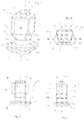
Figs. 3 to 6 are respectively a view in lateral perspective, a top view, a front elevation and a lateral elevation from the left of a stud of the studded tyre ofFig. 1 ; -
Fig. 7 shows a first preferred arrangement of studs in the tyre ofFig. 1 ; -
Fig. 8 shows a second preferred arrangement of studs in the tyre ofFig. 1 ; -
Fig. 9 shows a third preferred arrangement of studs in the tyre ofFig. 1 . - With reference to the attached drawings, a studded tyre is shown overall by 1.
- The tyre 1 generally comprises, in a radially outer position, a tread band 2, shaped as a toroid about an axis of rotation X of said tyre 1, which is disposed in a radially outer position on a belt structure of said tyre 1 according to a configuration which is known per se in the relevant technical field.
- In turn, the belt structure is coupled in a radially outer position to a carcass structure, both known per se and not shown in the appended drawings.
- The tread band 2 is made from elastomer material and is provided with a radially outer tread surface 3 designed to bring said tyre 1 into contact with the road surface during its rolling motion about the axis X.
- The tyre 1 is preferably of the directional type such that it has a preferential rolling direction shown by F in
Fig. 1 . In this way, an advancing direction Y tangential to the tread surface 3 and oriented in the rolling direction F is defined for each point of the tread surface 3. - A plurality of holes 4, identical with one another and positioned in an appropriate manner along the extension of the tread surface 3, is provided on the tread band 2. In greater detail, holes 4 are preferably obtained in a central portion and in lateral portions of said tread band 2.
- Each hole 4, preferably cylindrical, extends in a substantially radial direction and has an opening 4a at the tread surface 3 and a closed base 4b on the longitudinally opposite side.
- Each hole 4 houses in engagement a corresponding stud 10 comprising a body 11, housed in said hole 4 and extending along a longitudinal axis Z, and a pin 12, extending longitudinally from said body 11 so as to project from the tread surface 3 through the opening 4a externally to the hole 4.
- As a result of the resilience of the elastomer material from which the tread band 2 is made and the predetermined dimensions of the hole 4, the walls of the tread band 2 bounding the hole 4 are in direct contact substantially with the whole surface of the body 11, apart from the surface from which the pin 12 extends, and exert an action on the body 11 that retains the stud 10 within the hole 4.
- Each stud 10 has a first surface 10a and an opposite second surface 10b which may be defined as the projections of said stud 10 in a radial plane R passing through the longitudinal axis Z provided in the advancing direction Y and in the opposite direction, or vice versa.
- The body 11 of the stud 10 is preferably made from metal material, for instance steel, and comprises, on longitudinally opposite sides, a
base 13 and a head 14 connected together by a stem 15 extending along the longitudinal axis Z and having a smaller cross-section than thebase 13 and the head 14. - The
base 13 is housed in a radially inner position in the hole 4 and bears on the base 4b, while the head 14 is housed within the hole 4 in a radially outer position and is substantially flush with the tread surface 3. - The pin 12 is made from a material of high strength and resistance to wear, for instance tungsten carbide, and extends longitudinally from the head 14 so as to project from the hole 4 externally to the tread surface 3.
- As better shown in
Fig. 4 , thebase 13 has a configuration in plan view of substantially trapezoidal shape, on which a first side 16, belonging to the first surface 10a, and an opposite second side 17, belonging to the second surface 10b, are defined. Said first and second sides are disposed substantially parallel to the axis of rotation X of the tyre 1. They may also be disposed substantially perpendicular to the advancing direction Y. The first side 16 and second side 17 are joined together by opposite lateral flanks 18. - The configuration in plan view of said
base 13 may, for instance, be shaped substantially as an isosceles trapezium with rounded vertices, in which the first side 16 of thebase 13 represents the longer base of the trapezium, the second side 17 of thebase 13 represents the shorter base of the trapezium and the lateral flanks 18 represent the sides of the trapezium. - Preferably, the first side 16 is larger than the second side 17 by a percentage of between about 20% and about 50%. The dimension of the first side 16 may for instance be between about 8 mm and about 11 mm. The dimension of the second side 17 may for instance be between about 5 mm and 9 mm.
- The distance between the first side 16 and the second side 17, representing the height of the trapezium, may, for instance, be between about 5 mm and 9 mm.
- Towards the head 14, the
base 13 has a substantially planar surface 19 perpendicular to the longitudinal direction Z and appropriately coupled to the stem 15, while on the longitudinally opposite side, it has asurface 20 tapering towards the base 4b of the hole 4 so as to facilitate the insertion of the stud 10 in the hole 4 when the tyre 1 is being produced. - The first side 16 and second side 17 of the configuration in plan view of the base 13 are defined respectively by a first edge 16a and a second edge 17a belonging respectively to the first surface 10a and the second surface 10b. The first edge 16a and second edge 17a also define zones of contact between the base 13 and the wall of the tread band 2 bounding the hole 4.
- These contact zones of the base 13 are disposed on opposite sides with respect to the radial plane R of the tyre 1 passing through the longitudinal axis Z and are intended to counter the stresses on the pin 12 directed in the advancing direction Y or in the opposite direction.
- The edges 16a, 17a extend longitudinally over a relatively small measurement with respect to the dimension perpendicular to the longitudinal axis Z such that the contact zones of the base 13 extend prevalently in a dimension substantially perpendicular to the advancing direction Y.
- In the light of the above, the
base 13 is asymmetrical with respect to the radial plane R passing through the longitudinal axis Z. - The stem 15 has a substantially circular configuration in plan view with a diameter for instance of between about 4 mm and about 5 mm.
- The head 14, like the base 13, has a configuration in plan view of substantially trapezoidal shape, on which a first side 21, belonging to the first surface 10a, and an opposite second side 22, belonging to the second surface 10b, are defined. The first side 21 and second side 22 are preferably substantially parallel to the axis of rotation X of the tyre 1 and are joined together by opposite lateral flanks 23.
- Unlike said
base 13, however, the head 14 has a configuration in plan view which is rotated by 180° about the longitudinal axis Z with respect to that of thebase 13. - The configuration in plan view of the head 14 is preferably shaped substantially as an isosceles trapezium with rounded vertices, in which the first side 21 of the head 14 represents the smaller base of the trapezium, the second side 22 of the head 14 represents the longer base of the trapezium and the lateral flanks 23 represent the sides of the trapezium.
- Preferably, the second side 22 is larger than the first side 21 by a percentage of between about 20% and about 60%. The dimension of the first side 21 may for instance be between about 4 mm and about 7 mm, while the dimension of the second side 17 may be between about 6 mm and about 9 mm.
- The distance between the first side 21 and the second side 22, representing the height of the trapezium, may be between about 5 mm and about 9 mm.
- Preferably, the head 14 has a configuration in plan view having an area of dimensions reduced with respect to the area of the configuration in plan view of the
base 13. This area may be reduced, for instance, by a proportional factor of between 1.2 and 2.5. - The first side 21, the second side 22 and the lateral flanks 23 of the configuration in plan view of the head 14 are defined respectively by a first radial surface 24, a second radial surface 25 and opposite lateral radial surfaces 26 extending along the longitudinal axis Z. The radial surfaces 24, 25, 26 may for instance extend longitudinally over a measurement of between about 3.5 mm and about 5.5 mm.
- The radial surfaces 24, 25, 26 preferably have a concave portion of cylindrical type having an axis spaced from and substantially perpendicular to the longitudinal axis Z. In preferred configurations, they have a radius of curvature of between about 3 mm and about 17 mm.
- Preferably, the walls of the hole 4 in contact with said radial surfaces 24, 25, 26 have a convex profile designed to match the concave profile of said surfaces.
- Moreover, the front and rear radial surfaces 24 and 25, opposite one another with respect to the radial plane R and belonging respectively to the first surface 10a and the second surface 10b of the stud 10, respectively define zones of contact between the head 14 and the wall of the tread band 2 bounding the hole 4.
- The pin 12 of the stud 10 is configured in a configuration in plan view which is not symmetrical at least with respect to an axis and is preferably elongate. As shown in
Fig. 4 , the configuration in plan view is non-symmetrical with respect to the direction shown by R which also represents the main direction of extension of the configuration in plan view of the pin 12. Preferably, the stud 10 is disposed within the respective hole 4 such that the main direction of extension R of the configuration in plan view of the pin 12 is substantially parallel to the axis of rotation X of the tyre 1. - The pin 12 may extend from the head 14 over a measurement for instance of between about 1 mm and about 1.5 mm.
- The configuration in plan view of the pin 12 has a first side 30 and an opposite second side 31, belonging respectively to the first surface 10a and the second surface 10b of the stud 10.
- The first side 30 has a discontinuous profile in which at least one tooth is defined. In the preferred configuration shown in the drawings, two teeth 32 and 33 are defined in the discontinuous profile of the first side 30. At least some of the studs 10 engaged in the holes 4 provided in the tread surface 3 of the tyre 1 are disposed such that the teeth 32, 33 face in a direction substantially opposite to the advancing direction Y. Other studs 10 may be partly disposed such that the teeth 32, 33 face in a direction substantially concordant with the advancing direction Y.
- The second side 31 of the configuration in plan view of the pin 12 has a substantially planar profile. The studs 10 are preferably disposed such that the second side 31 is disposed substantially parallel to the axis of rotation X of the tyre 1. The second side 31 is part of a portion of substantially trapezoidal shape of the configuration in plan view of the pin, opposite the tips 32, 33.
- For the production of the studded tyre 1, the holes 4 are preferably obtained during the stage of moulding and vulcanization of the tread band 2, by appropriately shaped pins extending radially from the inner walls of the mould.
- The studs 10, made by a separate process, are then inserted in the holes 4, typically by means of a semi-automatic machine, which is known per se, such that the
base 13 is housed in the hole 4 and bears on the base 4b and the pin 12 projects from the opening 4a of the hole 4. - The studs 10 are also inserted in the holes 4 with a predetermined orientation and guided by the first side 30 of the profile of the configuration in plan view of the pin 12. At least a first plurality of studs 10 is inserted in the respective holes such that the first side 30 of the profile of the pin 12 of the studs 10 of the first plurality faces in a direction substantially opposite to the advancing direction Y of the tyre. A second plurality of studs 10 may be inserted such that the first side 30 of the profile of the pin 12 of the studs 10 of the second plurality faces in a direction substantially concordant with the advancing direction Y of the tyre. In the first plurality of studs 10, the second side 31 of the profile of the pin 12 therefore faces in the advancing direction Y of the tyre. In the second plurality of studs 10, the second side 31 of the profile of the pin 12 therefore faces in a direction opposite to the advancing direction Y of the tyre.
- The tyre 1 is mounted on a vehicle such that during the forward travel of the vehicle it rotates about the axis of rotation X. In the case of a directional tyre, it is mounted such that it rotates in the preferential rolling direction F.
- During acceleration/deceleration (including braking) of the vehicle, and also when cornering and/or generally in the case of lateral stress , the pin 12 contacts the road surface, cutting any icy surface and causing a tangential stress on the stud 10.
- This stress applied to a longitudinal end of said stud 10 may be assimilated with a force acting on the barycentre of the stud 10 combined with a pair of forces which tend to cause the stud 10 to oscillate about an axis of oscillation passing through its barycentre and substantially perpendicular to the longitudinal axis Z. In particular, in the case of traction/braking and therefore in the case of purely longitudinal forces, the axis of oscillation will be parallel to the axis of rotation X, while in the case of purely lateral forces, the axis of oscillation will be parallel to the advancing direction Y. In the most common case, there will be a combination of lateral and longitudinal forces, and the axis of oscillation will therefore have a given inclination with respect to the axis of rotation X and the direction Y.
- This pair of forces which tends to cause the stud 10 to oscillate within the hole 4 is appropriately countered by the contact zones of said
base 13 and the contact zones of said head 14. - In this way, the oscillating movement of the stud is very small, such that it can be accommodated by the wall of the hole 4, making use of the properties of deformability of the elastomer material of the tread band 2, and thus preventing any mutual movement between the stud 10 and the wall of the hole 4 which, over time, could cause the gradual wear of the latter.
- In the preferred configuration shown in
Figs. 2 to 6 , the wide extension of the radial surfaces 24, 25 of the stud 10 also makes it possible even more effectively to counter the force acting on the barycentre of the stud 10. -
Figs. 7, 8 and 9 diagrammatically show some preferred configurations (or layouts) of the arrangement of the studs 10 in the tread band 2 of the tyre 1 of the present invention. The studs 10 are shown diagrammatically by means of the configuration in plan view of their pin 12. In the diagrammatic illustration shown inFigs. 7, 8 and 9 , four adjacent pins are shown: the two central pins represent a plurality of studs disposed in a central portion of the tread band 2 of the tyre 1, while the lateral pins represent a plurality of studs disposed in lateral portions of the tread band 2 of the tyre 1 (said lateral portions being adjacent to the central portion and disposed towards the shoulder of the tyre). The two central pins may, for instance, represent a plurality of studs disposed in one or a plurality of rows of blocks disposed in the central portion of the tread band; the two lateral pins may represent a plurality of studs disposed in one or a plurality of rows of blocks disposed in the lateral portions of the tread band. -
Fig. 7 shows a first arrangement in which a first plurality of studs A having pins with tips facing in a direction substantially opposite to the advancing direction Y of the tyre is disposed in lateral portions of the tread band, and a second plurality of studs B having pins with tips facing in a direction concordant with the advancing direction Y of the tyre is disposed in a central portion of the tread band. -
Fig. 8 shows a second arrangement in which a first plurality of studs A having pins with tips facing in a direction substantially opposite to the advancing direction Y of the tyre is disposed in a central portion of the tread band, and a second plurality of studs B having pins with tips facing in a direction concordant with the advancing direction Y of the tyre is disposed in lateral portions of the tread band. -
Fig. 9 shows a third arrangement in which the plurality of studs A having pins with tips facing in a direction substantially opposite to the advancing direction Y of the tyre is disposed in all portions of the tread band. - Other arrangements in which some of the studs are disposed such that the tooth or teeth of the pin substantially face in the direction opposite to the advancing direction Y of the tyre are possible. The illustrations of
Figs. 7, 8 and 9 are no more than possible examples. - The Applicants have conducted a series of handling tests on snow with a VW Golf car equipped with 205/55 R16 tyres comprising studs embodied in accordance with the preceding specification.
- Tyres in which said studs were inserted in the holes provided in the surface of the tread band in various arrangements were in particular tested.
- In a first arrangement (layout 1 - comparison), all the studs were inserted such that the teeth of the pin faced in the advancing direction of the tyre, in all portions of the tread.
- In a second arrangement (layout 2 - invention), the studs were inserted such that the teeth of the pin faced in the advancing direction of the tyre in the central portion of the tread, and in the direction opposite to the advancing direction of the tyre in the lateral portions of the tread. In particular, of the total of 130 studs inserted in the tread of each tyre, 68 studs were positioned such that the teeth of the pin faced in the direction opposite to the advancing direction of the tyre.
- In a third arrangement (layout 3 - invention), the studs were inserted such that the teeth of the pin faced in the direction opposite to the advancing direction of the tyre in the central portion of the tread, and in the advancing direction of the tyre in the lateral portions of the tread. In particular, of the total of 130 studs inserted in the tread of each tyre, 62 studs were positioned such that the teeth of the pin faced in the direction opposite to the advancing direction of the tyre.
- In a fourth arrangement (layout 4 - invention), all the studs were inserted such that the teeth of the pin faced in the direction opposite to the advancing direction of the tyre, in all portions of the tread.
- Table 1 summarizes the results of a traction and braking test (carried out on a vehicle fitted with instruments) on an icy surface, taking the performance of tyres equipped with conventional studs as a reference. Starting traction from stationary and the braking distance from a speed of 50 km/h to 0 km/h were measured for the test.
Table 1 Traction Braking Comparison: Layout 1 103 113 Invention: Layout 2 111 114 Invention: Layout 3 107 119 Invention: Layout 4 107 121 - As can be seen, all the layouts 2-4 in which at least some of the studs had pins with teeth facing in the direction opposite to the advancing direction of the tyre obtained better results in terms of performance during both traction and braking than layout 1 in which all the teeth had pins with teeth facing in the direction concordant with the advancing direction of the tyre.
- The following Table 2 summarises the results of the subjective handling tests assessed (in respect of various factors) by a professional tester on an icy surface.
Table 2 Layout 1 Layout 2 Layout 3 Layout 4 Traction 7 7 6.5 6.5 Braking efficiency 7 7 6.5 6.5 Skid effect 7 7 6.5 6.5 Steerability 7 7 6.5 6 Understeering 7 7 6.5 6 Oversteering 6 7 6 6 Progression of loss of grip 6.5 7 6 6 Recovery 6 6.5 6 6 Lateral grip 6 7 6 6 - Table 3 summarises the results of the subjective handling tests assessed (in respect of various factors) by a professional tester on a snow-covered surface.
Table 3 Layout 1 Layout 2 Layout 3 Layout 4 Traction 7.5 7.5 7 7 Braking efficiency 7.5 7.5 7 7 Steerability 7 7 6.5 6.5 Understeering 7 7.5 7 6.5 Oversteering 6.5 7 6.5 6.5 Progression of loss of grip 7 7 7 6.5 Recovery 6.5 7 6.5 6.5 Lateral grip 7 7 6.5 6.5 - The results shown in Tables 2 and 3 show that layout 2 was clearly better, making it possible to provide the vehicle with optimum handling on both icy and snow-covered surfaces, although it did not have the best results in absolute terms in terms of traction and braking (see Table 1). Layouts 3 and 4 enabled adequate handling, but performed better in terms of traction and braking (see Table 1).
- Depending on requirements, a designer can obviously choose the best configuration depending on the type(s) of performance that are considered most important.
Claims (15)
- A studded tyre (1) comprising:- a tread band (2) on which a tread surface (3) of said tyre is defined,- a plurality of holes (4) provided on said tread band (2) and open on said tread surface (3) in which a corresponding plurality of studs (10) is housed in engagement, each stud comprising a body (11) housed in one of said holes, and a pin (12) projecting from said tread band (2) externally to said hole (4),wherein- said pin (12) has a configuration in plan view which is not symmetrical at least with respect to an axis, comprising a first side (30) having a profile on which at least one tip (32, 33) is defined, and a second side (31) having a substantially planar profile, said second side (31) being opposite said first side,- said plurality of studs (10) comprises a first plurality of studs (A), wherein the pins of the studs (10) of said first plurality have their respective tips (32, 33) facing in a direction substantially opposite to an advancing direction (Y) of said tyre (1),- said body (11) of each stud (10) of said plurality of studs comprises a base (13), longitudinally opposite said pin (12) and housed in a radially inner position of the respective hole (4),- said pin (12) extends longitudinally from a head (14) of said body (11) of each stud (10) of said plurality of studs, said head being housed in said hole (4) in a radially outer position with respect to said base (13) of said stud, and- said head (14) has a configuration in plan view analogous to that of said base (13) and is rotated by substantially 180° about a longitudinal axis (Z) of said stud (10) with respect to the configuration in plan view of said base (13),wherein the configuration in plan view means the orthogonal projection in a plane perpendicular to a longitudinal axis of the stud.
- A tyre according to claim 1, wherein said plurality of studs (10) comprises a second plurality of studs (B), wherein the pins of the studs (10) of said second plurality have their respective tips (32, 33) facing substantially towards said advancing direction (Y) of said tyre (1).
- A tyre according to claim 1 or 2, wherein said first plurality of studs (A) is positioned in lateral portions of said tread band (2).
- A tyre according to claim 2 or 3, wherein said second plurality of studs (B) is positioned in a central portion of said tread band (2).
- A tyre according to any one of the preceding claims, wherein said first side (30) of the configuration in plan view of said pin (12) has a profile on which at least two tips (32, 33) are defined.
- A tyre according to any one of the preceding claims, wherein said second side (31) of the configuration in plan view of said pin (12) is included in a portion of substantially trapezoidal shape of said configuration in plan view of said pin (12) opposite said at least one tip (32, 33).
- A tyre according to any one of the preceding claims, wherein said configuration in plan view of said pin (12) is elongate and has a main direction of extension, and wherein each stud (10) of said plurality of studs is positioned such that said main direction of extension extends substantially parallel to an axis of rotation (X) of said tyre (1).
- A tyre according to any one of the preceding claims, wherein said base has a configuration in plan view on which a first side (16) and an opposite second side (17) are defined and disposed substantially parallel to an axis of rotation (X) of said tyre.
- A tyre according to claim 8, wherein said base (13) has a substantially trapezoidal configuration in plan view, said first side (16) of said base (13) representing a longer base of said trapezium and said second side (17) representing a shorter base of said trapezium.
- A tyre according to claim 8 or 9, wherein said first side (30) of said configuration in plan view of said pin (12) is disposed in a direction concordant with said first side (16) of said base (13).
- A tyre according to any one of the preceding claims, wherein said head has a configuration in plan view in which a first side (21) and an opposite second side (22) are defined and disposed substantially parallel to said axis of rotation (X) of said tyre.
- A tyre according to claim 11, wherein said first side (21) of said head has a smaller extension than said second side (22) of said head.
- A tyre according to claim 11 or 12, wherein said head (14) has a substantially trapezoidal configuration in plan view, said first side (21) of said head representing a shorter base of said trapezium and said second side (22) of said head representing a longer base of said trapezium.
- A tyre according to any one of claims 11 to 13, wherein said first side (30) of said configuration in plan view of said pin (12) is disposed in a direction concordant with said first side (21) of said head (14).
- A tyre according to any one of the preceding claims , wherein said head (14) has a configuration in plan view having an area of dimensions reduced by a proportional factor of between about 1.2 and about 2.5 with respect to the area of the configuration in plan view of said base (13).
Applications Claiming Priority (3)
| Application Number | Priority Date | Filing Date | Title |
|---|---|---|---|
| ITPD20130025 | 2013-02-06 | ||
| US201361792292P | 2013-03-15 | 2013-03-15 | |
| PCT/IB2014/058755 WO2014122570A1 (en) | 2013-02-06 | 2014-02-03 | A studded tyre and a method for improving the performance of a studded tyre |
Publications (2)
| Publication Number | Publication Date |
|---|---|
| EP2953801A1 EP2953801A1 (en) | 2015-12-16 |
| EP2953801B1 true EP2953801B1 (en) | 2018-05-16 |
Family
ID=48096052
Family Applications (1)
| Application Number | Title | Priority Date | Filing Date |
|---|---|---|---|
| EP14716919.7A Not-in-force EP2953801B1 (en) | 2013-02-06 | 2014-02-03 | A studded tyre and a method for improving the performance of a studded tyre |
Country Status (5)
| Country | Link |
|---|---|
| EP (1) | EP2953801B1 (en) |
| CN (1) | CN104955662B (en) |
| CA (1) | CA2897677A1 (en) |
| RU (1) | RU2667105C2 (en) |
| WO (1) | WO2014122570A1 (en) |
Cited By (2)
| Publication number | Priority date | Publication date | Assignee | Title |
|---|---|---|---|---|
| EP4461568A1 (en) * | 2023-05-08 | 2024-11-13 | Nokian Renkaat Oyj | A studded tyre having grooves |
| EP4461567A1 (en) * | 2023-05-08 | 2024-11-13 | Nokian Renkaat Oyj | A studded tyre having sipes |
Families Citing this family (15)
| Publication number | Priority date | Publication date | Assignee | Title |
|---|---|---|---|---|
| JP6515498B2 (en) * | 2014-11-18 | 2019-05-22 | 横浜ゴム株式会社 | Pneumatic tire |
| WO2016080294A1 (en) * | 2014-11-21 | 2016-05-26 | 株式会社ブリヂストン | Stud and studdable tire |
| US10377186B2 (en) | 2014-12-15 | 2019-08-13 | The Yokohama Rubber Co., Ltd. | Pneumatic tire |
| US10647163B2 (en) | 2015-06-12 | 2020-05-12 | The Yokohama Rubber Co., Ltd. | Stud pin and pneumatic tire |
| RU2681454C1 (en) | 2015-10-07 | 2019-03-06 | Дзе Йокогама Раббер Ко., Лтд. | Pneumatic tire and spike stud |
| JP6579906B2 (en) * | 2015-10-16 | 2019-09-25 | 株式会社ブリヂストン | tire |
| DE102015225224A1 (en) * | 2015-12-15 | 2017-06-22 | Continental Reifen Deutschland Gmbh | Vehicle tires |
| JP6730161B2 (en) | 2016-10-26 | 2020-07-29 | Toyo Tire株式会社 | Stud pin and pneumatic tire with stud pin |
| JP6860063B2 (en) * | 2017-02-28 | 2021-04-14 | 横浜ゴム株式会社 | Stud pins and stud tires |
| EP3421266B1 (en) * | 2017-06-28 | 2022-06-01 | Spikesafe OY | A discharge head for an anti-skid insert installation tool, an anti-skid insert and a system for providing a traction device with an anti-skid insert |
| DE102018201611A1 (en) * | 2018-02-02 | 2019-08-08 | Continental Reifen Deutschland Gmbh | Spike and pneumatic vehicle tire with spikes |
| DE202018006249U1 (en) | 2018-03-15 | 2019-10-04 | Sitek-Spikes Gmbh & Co. Kg | Spike tires |
| FI3674105T3 (en) * | 2018-12-28 | 2025-01-20 | Sumitomo Rubber Ind | Advanced ice grip device and pneumatic tire with advanced ice grip device |
| JP7056695B2 (en) * | 2020-07-29 | 2022-04-19 | 横浜ゴム株式会社 | Stud pins and tires with them |
| DE102021213319A1 (en) * | 2021-11-26 | 2023-06-01 | Continental Reifen Deutschland Gmbh | Spike and combination of spikes |
Family Cites Families (11)
| Publication number | Priority date | Publication date | Assignee | Title |
|---|---|---|---|---|
| FR447945A (en) * | 1912-09-04 | 1913-01-18 | Jean Joseph Gonon | Non-slip rivets for wheel tires |
| ATE381448T1 (en) | 2000-10-18 | 2008-01-15 | Continental Ag | SPIKE FOR VEHICLE TIRES |
| FI123702B (en) | 2002-11-04 | 2013-09-30 | Nokian Renkaat Oyj | Vehicle studded pneumatic tire |
| FI123775B (en) * | 2002-12-11 | 2013-10-31 | Nokian Renkaat Oyj | Installation of non-circular anti-slip studs in vehicle tires |
| DE102004056823A1 (en) * | 2004-11-24 | 2006-06-08 | Continental Aktiengesellschaft | Spikestift, Spike and vehicle tires with spikes mounted in the tread |
| FI119182B (en) | 2005-12-16 | 2008-08-29 | Scason Oy | Double for double deck |
| WO2009068744A1 (en) | 2007-11-26 | 2009-06-04 | Sancus Oy | Anti-skid stud for a tyre |
| DE102009042720A1 (en) | 2009-09-23 | 2011-04-07 | Sitek Spikes Gmbh & Co. Kg | anti-skid |
| JP5706192B2 (en) | 2011-03-01 | 2015-04-22 | 株式会社ブリヂストン | Tire spike |
| US20130000807A1 (en) * | 2011-06-28 | 2013-01-03 | Frederic Michel-Jean Pons | Anti-skid stud for insertion into the tread of a vehicle tire and pneumatic tire comprising such anti-skid studs |
| JP5883246B2 (en) * | 2011-07-22 | 2016-03-09 | 株式会社ブリヂストン | Tire spikes and spike tires |
-
2014
- 2014-02-03 WO PCT/IB2014/058755 patent/WO2014122570A1/en not_active Ceased
- 2014-02-03 CN CN201480006675.5A patent/CN104955662B/en active Active
- 2014-02-03 CA CA2897677A patent/CA2897677A1/en not_active Abandoned
- 2014-02-03 EP EP14716919.7A patent/EP2953801B1/en not_active Not-in-force
- 2014-02-03 RU RU2015136978A patent/RU2667105C2/en active
Non-Patent Citations (1)
| Title |
|---|
| None * |
Cited By (2)
| Publication number | Priority date | Publication date | Assignee | Title |
|---|---|---|---|---|
| EP4461568A1 (en) * | 2023-05-08 | 2024-11-13 | Nokian Renkaat Oyj | A studded tyre having grooves |
| EP4461567A1 (en) * | 2023-05-08 | 2024-11-13 | Nokian Renkaat Oyj | A studded tyre having sipes |
Also Published As
| Publication number | Publication date |
|---|---|
| RU2667105C2 (en) | 2018-09-14 |
| CN104955662A (en) | 2015-09-30 |
| CN104955662B (en) | 2017-08-11 |
| EP2953801A1 (en) | 2015-12-16 |
| WO2014122570A1 (en) | 2014-08-14 |
| CA2897677A1 (en) | 2014-08-14 |
| RU2015136978A (en) | 2017-03-13 |
Similar Documents
| Publication | Publication Date | Title |
|---|---|---|
| CA2897677A1 (en) | A studded tyre and a method for improving the performance of a studded tyre | |
| CN101181864B (en) | Pneumatic tire for off-road traveling | |
| EP3539798B1 (en) | Tyre | |
| JP6786927B2 (en) | Pneumatic tires | |
| EP2116397B1 (en) | Pneumatic tire | |
| CN108859613B (en) | Tyre for vehicle wheels | |
| EP3549795B1 (en) | Method for improving the performance of a studded tyre and studded tyre produced according to this method | |
| US11040576B2 (en) | Tire with grooves having variable depth | |
| CN101588934B (en) | pneumatic tire | |
| US20070089821A1 (en) | Pneumatic tire and mold | |
| CN105873775A (en) | Tyre for vehicle wheels having improved tread pattern | |
| US20230322028A1 (en) | Tire | |
| EP3530488A1 (en) | Tyre for winter | |
| CN101992659B (en) | Pneumatic tire | |
| CN101472748A (en) | Pneumatic tire | |
| JP2018531842A (en) | Twisted sipe | |
| CN108778780B (en) | tires for vehicle wheels | |
| EP3360700B1 (en) | Pneumatic tire and stud pin | |
| JP4717865B2 (en) | Pneumatic tire | |
| JP2007182096A (en) | Pneumatic tire for running on rough terrain | |
| JP5503185B2 (en) | Construction vehicle tire and method of use thereof | |
| CN118284523A (en) | Studs for vehicle wheels and studded tires |
Legal Events
| Date | Code | Title | Description |
|---|---|---|---|
| PUAI | Public reference made under article 153(3) epc to a published international application that has entered the european phase |
Free format text: ORIGINAL CODE: 0009012 |
|
| 17P | Request for examination filed |
Effective date: 20150623 |
|
| AK | Designated contracting states |
Kind code of ref document: A1 Designated state(s): AL AT BE BG CH CY CZ DE DK EE ES FI FR GB GR HR HU IE IS IT LI LT LU LV MC MK MT NL NO PL PT RO RS SE SI SK SM TR |
|
| AX | Request for extension of the european patent |
Extension state: BA ME |
|
| DAX | Request for extension of the european patent (deleted) | ||
| STAA | Information on the status of an ep patent application or granted ep patent |
Free format text: STATUS: EXAMINATION IS IN PROGRESS |
|
| 17Q | First examination report despatched |
Effective date: 20170124 |
|
| GRAP | Despatch of communication of intention to grant a patent |
Free format text: ORIGINAL CODE: EPIDOSNIGR1 |
|
| STAA | Information on the status of an ep patent application or granted ep patent |
Free format text: STATUS: GRANT OF PATENT IS INTENDED |
|
| INTG | Intention to grant announced |
Effective date: 20180126 |
|
| GRAS | Grant fee paid |
Free format text: ORIGINAL CODE: EPIDOSNIGR3 |
|
| GRAA | (expected) grant |
Free format text: ORIGINAL CODE: 0009210 |
|
| STAA | Information on the status of an ep patent application or granted ep patent |
Free format text: STATUS: THE PATENT HAS BEEN GRANTED |
|
| AK | Designated contracting states |
Kind code of ref document: B1 Designated state(s): AL AT BE BG CH CY CZ DE DK EE ES FI FR GB GR HR HU IE IS IT LI LT LU LV MC MK MT NL NO PL PT RO RS SE SI SK SM TR |
|
| REG | Reference to a national code |
Ref country code: GB Ref legal event code: FG4D |
|
| REG | Reference to a national code |
Ref country code: CH Ref legal event code: EP |
|
| REG | Reference to a national code |
Ref country code: IE Ref legal event code: FG4D |
|
| REG | Reference to a national code |
Ref country code: DE Ref legal event code: R096 Ref document number: 602014025529 Country of ref document: DE |
|
| REG | Reference to a national code |
Ref country code: AT Ref legal event code: REF Ref document number: 999198 Country of ref document: AT Kind code of ref document: T Effective date: 20180615 |
|
| REG | Reference to a national code |
Ref country code: SE Ref legal event code: TRGR |
|
| REG | Reference to a national code |
Ref country code: NL Ref legal event code: MP Effective date: 20180516 |
|
| REG | Reference to a national code |
Ref country code: LT Ref legal event code: MG4D |
|
| PG25 | Lapsed in a contracting state [announced via postgrant information from national office to epo] |
Ref country code: ES Free format text: LAPSE BECAUSE OF FAILURE TO SUBMIT A TRANSLATION OF THE DESCRIPTION OR TO PAY THE FEE WITHIN THE PRESCRIBED TIME-LIMIT Effective date: 20180516 Ref country code: LT Free format text: LAPSE BECAUSE OF FAILURE TO SUBMIT A TRANSLATION OF THE DESCRIPTION OR TO PAY THE FEE WITHIN THE PRESCRIBED TIME-LIMIT Effective date: 20180516 Ref country code: NO Free format text: LAPSE BECAUSE OF FAILURE TO SUBMIT A TRANSLATION OF THE DESCRIPTION OR TO PAY THE FEE WITHIN THE PRESCRIBED TIME-LIMIT Effective date: 20180816 Ref country code: BG Free format text: LAPSE BECAUSE OF FAILURE TO SUBMIT A TRANSLATION OF THE DESCRIPTION OR TO PAY THE FEE WITHIN THE PRESCRIBED TIME-LIMIT Effective date: 20180816 |
|
| PG25 | Lapsed in a contracting state [announced via postgrant information from national office to epo] |
Ref country code: GR Free format text: LAPSE BECAUSE OF FAILURE TO SUBMIT A TRANSLATION OF THE DESCRIPTION OR TO PAY THE FEE WITHIN THE PRESCRIBED TIME-LIMIT Effective date: 20180817 Ref country code: NL Free format text: LAPSE BECAUSE OF FAILURE TO SUBMIT A TRANSLATION OF THE DESCRIPTION OR TO PAY THE FEE WITHIN THE PRESCRIBED TIME-LIMIT Effective date: 20180516 Ref country code: RS Free format text: LAPSE BECAUSE OF FAILURE TO SUBMIT A TRANSLATION OF THE DESCRIPTION OR TO PAY THE FEE WITHIN THE PRESCRIBED TIME-LIMIT Effective date: 20180516 Ref country code: LV Free format text: LAPSE BECAUSE OF FAILURE TO SUBMIT A TRANSLATION OF THE DESCRIPTION OR TO PAY THE FEE WITHIN THE PRESCRIBED TIME-LIMIT Effective date: 20180516 Ref country code: HR Free format text: LAPSE BECAUSE OF FAILURE TO SUBMIT A TRANSLATION OF THE DESCRIPTION OR TO PAY THE FEE WITHIN THE PRESCRIBED TIME-LIMIT Effective date: 20180516 |
|
| REG | Reference to a national code |
Ref country code: AT Ref legal event code: MK05 Ref document number: 999198 Country of ref document: AT Kind code of ref document: T Effective date: 20180516 |
|
| PG25 | Lapsed in a contracting state [announced via postgrant information from national office to epo] |
Ref country code: SK Free format text: LAPSE BECAUSE OF FAILURE TO SUBMIT A TRANSLATION OF THE DESCRIPTION OR TO PAY THE FEE WITHIN THE PRESCRIBED TIME-LIMIT Effective date: 20180516 Ref country code: RO Free format text: LAPSE BECAUSE OF FAILURE TO SUBMIT A TRANSLATION OF THE DESCRIPTION OR TO PAY THE FEE WITHIN THE PRESCRIBED TIME-LIMIT Effective date: 20180516 Ref country code: DK Free format text: LAPSE BECAUSE OF FAILURE TO SUBMIT A TRANSLATION OF THE DESCRIPTION OR TO PAY THE FEE WITHIN THE PRESCRIBED TIME-LIMIT Effective date: 20180516 Ref country code: PL Free format text: LAPSE BECAUSE OF FAILURE TO SUBMIT A TRANSLATION OF THE DESCRIPTION OR TO PAY THE FEE WITHIN THE PRESCRIBED TIME-LIMIT Effective date: 20180516 Ref country code: AT Free format text: LAPSE BECAUSE OF FAILURE TO SUBMIT A TRANSLATION OF THE DESCRIPTION OR TO PAY THE FEE WITHIN THE PRESCRIBED TIME-LIMIT Effective date: 20180516 Ref country code: EE Free format text: LAPSE BECAUSE OF FAILURE TO SUBMIT A TRANSLATION OF THE DESCRIPTION OR TO PAY THE FEE WITHIN THE PRESCRIBED TIME-LIMIT Effective date: 20180516 Ref country code: CZ Free format text: LAPSE BECAUSE OF FAILURE TO SUBMIT A TRANSLATION OF THE DESCRIPTION OR TO PAY THE FEE WITHIN THE PRESCRIBED TIME-LIMIT Effective date: 20180516 |
|
| REG | Reference to a national code |
Ref country code: DE Ref legal event code: R097 Ref document number: 602014025529 Country of ref document: DE |
|
| PG25 | Lapsed in a contracting state [announced via postgrant information from national office to epo] |
Ref country code: SM Free format text: LAPSE BECAUSE OF FAILURE TO SUBMIT A TRANSLATION OF THE DESCRIPTION OR TO PAY THE FEE WITHIN THE PRESCRIBED TIME-LIMIT Effective date: 20180516 |
|
| PLBE | No opposition filed within time limit |
Free format text: ORIGINAL CODE: 0009261 |
|
| STAA | Information on the status of an ep patent application or granted ep patent |
Free format text: STATUS: NO OPPOSITION FILED WITHIN TIME LIMIT |
|
| 26N | No opposition filed |
Effective date: 20190219 |
|
| PG25 | Lapsed in a contracting state [announced via postgrant information from national office to epo] |
Ref country code: SI Free format text: LAPSE BECAUSE OF FAILURE TO SUBMIT A TRANSLATION OF THE DESCRIPTION OR TO PAY THE FEE WITHIN THE PRESCRIBED TIME-LIMIT Effective date: 20180516 |
|
| REG | Reference to a national code |
Ref country code: CH Ref legal event code: PL |
|
| GBPC | Gb: european patent ceased through non-payment of renewal fee |
Effective date: 20190203 |
|
| PG25 | Lapsed in a contracting state [announced via postgrant information from national office to epo] |
Ref country code: LU Free format text: LAPSE BECAUSE OF NON-PAYMENT OF DUE FEES Effective date: 20190203 Ref country code: MC Free format text: LAPSE BECAUSE OF FAILURE TO SUBMIT A TRANSLATION OF THE DESCRIPTION OR TO PAY THE FEE WITHIN THE PRESCRIBED TIME-LIMIT Effective date: 20180516 |
|
| REG | Reference to a national code |
Ref country code: BE Ref legal event code: MM Effective date: 20190228 |
|
| REG | Reference to a national code |
Ref country code: IE Ref legal event code: MM4A |
|
| PG25 | Lapsed in a contracting state [announced via postgrant information from national office to epo] |
Ref country code: AL Free format text: LAPSE BECAUSE OF FAILURE TO SUBMIT A TRANSLATION OF THE DESCRIPTION OR TO PAY THE FEE WITHIN THE PRESCRIBED TIME-LIMIT Effective date: 20180516 |
|
| PG25 | Lapsed in a contracting state [announced via postgrant information from national office to epo] |
Ref country code: LI Free format text: LAPSE BECAUSE OF NON-PAYMENT OF DUE FEES Effective date: 20190228 Ref country code: CH Free format text: LAPSE BECAUSE OF NON-PAYMENT OF DUE FEES Effective date: 20190228 |
|
| PG25 | Lapsed in a contracting state [announced via postgrant information from national office to epo] |
Ref country code: GB Free format text: LAPSE BECAUSE OF NON-PAYMENT OF DUE FEES Effective date: 20190203 Ref country code: IE Free format text: LAPSE BECAUSE OF NON-PAYMENT OF DUE FEES Effective date: 20190203 |
|
| PG25 | Lapsed in a contracting state [announced via postgrant information from national office to epo] |
Ref country code: BE Free format text: LAPSE BECAUSE OF NON-PAYMENT OF DUE FEES Effective date: 20190228 Ref country code: FR Free format text: LAPSE BECAUSE OF NON-PAYMENT OF DUE FEES Effective date: 20190228 |
|
| PG25 | Lapsed in a contracting state [announced via postgrant information from national office to epo] |
Ref country code: TR Free format text: LAPSE BECAUSE OF FAILURE TO SUBMIT A TRANSLATION OF THE DESCRIPTION OR TO PAY THE FEE WITHIN THE PRESCRIBED TIME-LIMIT Effective date: 20180516 |
|
| PG25 | Lapsed in a contracting state [announced via postgrant information from national office to epo] |
Ref country code: PT Free format text: LAPSE BECAUSE OF FAILURE TO SUBMIT A TRANSLATION OF THE DESCRIPTION OR TO PAY THE FEE WITHIN THE PRESCRIBED TIME-LIMIT Effective date: 20180917 Ref country code: MT Free format text: LAPSE BECAUSE OF NON-PAYMENT OF DUE FEES Effective date: 20190203 |
|
| PG25 | Lapsed in a contracting state [announced via postgrant information from national office to epo] |
Ref country code: CY Free format text: LAPSE BECAUSE OF FAILURE TO SUBMIT A TRANSLATION OF THE DESCRIPTION OR TO PAY THE FEE WITHIN THE PRESCRIBED TIME-LIMIT Effective date: 20180516 |
|
| PG25 | Lapsed in a contracting state [announced via postgrant information from national office to epo] |
Ref country code: IS Free format text: LAPSE BECAUSE OF FAILURE TO SUBMIT A TRANSLATION OF THE DESCRIPTION OR TO PAY THE FEE WITHIN THE PRESCRIBED TIME-LIMIT Effective date: 20180916 |
|
| PG25 | Lapsed in a contracting state [announced via postgrant information from national office to epo] |
Ref country code: HU Free format text: LAPSE BECAUSE OF FAILURE TO SUBMIT A TRANSLATION OF THE DESCRIPTION OR TO PAY THE FEE WITHIN THE PRESCRIBED TIME-LIMIT; INVALID AB INITIO Effective date: 20140203 |
|
| PG25 | Lapsed in a contracting state [announced via postgrant information from national office to epo] |
Ref country code: MK Free format text: LAPSE BECAUSE OF FAILURE TO SUBMIT A TRANSLATION OF THE DESCRIPTION OR TO PAY THE FEE WITHIN THE PRESCRIBED TIME-LIMIT Effective date: 20180516 |
|
| PGFP | Annual fee paid to national office [announced via postgrant information from national office to epo] |
Ref country code: FI Payment date: 20240226 Year of fee payment: 11 Ref country code: DE Payment date: 20240228 Year of fee payment: 11 |
|
| PGFP | Annual fee paid to national office [announced via postgrant information from national office to epo] |
Ref country code: SE Payment date: 20240307 Year of fee payment: 11 Ref country code: IT Payment date: 20240222 Year of fee payment: 11 |
|
| REG | Reference to a national code |
Ref country code: DE Ref legal event code: R119 Ref document number: 602014025529 Country of ref document: DE |
|
| REG | Reference to a national code |
Ref country code: SE Ref legal event code: EUG |
|
| PG25 | Lapsed in a contracting state [announced via postgrant information from national office to epo] |
Ref country code: FI Free format text: LAPSE BECAUSE OF NON-PAYMENT OF DUE FEES Effective date: 20250203 |
|
| PG25 | Lapsed in a contracting state [announced via postgrant information from national office to epo] |
Ref country code: DE Free format text: LAPSE BECAUSE OF NON-PAYMENT OF DUE FEES Effective date: 20250902 |
|
| PG25 | Lapsed in a contracting state [announced via postgrant information from national office to epo] |
Ref country code: IT Free format text: LAPSE BECAUSE OF NON-PAYMENT OF DUE FEES Effective date: 20250203 |