EP2116397B1 - Pneumatic tire - Google Patents
Pneumatic tire Download PDFInfo
- Publication number
- EP2116397B1 EP2116397B1 EP07859952A EP07859952A EP2116397B1 EP 2116397 B1 EP2116397 B1 EP 2116397B1 EP 07859952 A EP07859952 A EP 07859952A EP 07859952 A EP07859952 A EP 07859952A EP 2116397 B1 EP2116397 B1 EP 2116397B1
- Authority
- EP
- European Patent Office
- Prior art keywords
- groove
- tire
- main groove
- stone trapping
- tread
- Prior art date
- Legal status (The legal status is an assumption and is not a legal conclusion. Google has not performed a legal analysis and makes no representation as to the accuracy of the status listed.)
- Not-in-force
Links
- 239000004575 stone Substances 0.000 claims abstract description 72
- 238000005452 bending Methods 0.000 claims abstract description 21
- 238000005259 measurement Methods 0.000 description 5
- 230000000694 effects Effects 0.000 description 3
- 239000011324 bead Substances 0.000 description 2
- 239000012141 concentrate Substances 0.000 description 2
- 230000003247 decreasing effect Effects 0.000 description 2
- 238000009434 installation Methods 0.000 description 2
- 206010016256 fatigue Diseases 0.000 description 1
- 238000004519 manufacturing process Methods 0.000 description 1
- 238000012986 modification Methods 0.000 description 1
- 230000004048 modification Effects 0.000 description 1
- XLYOFNOQVPJJNP-UHFFFAOYSA-N water Substances O XLYOFNOQVPJJNP-UHFFFAOYSA-N 0.000 description 1
Images


Classifications
-
- B—PERFORMING OPERATIONS; TRANSPORTING
- B60—VEHICLES IN GENERAL
- B60C—VEHICLE TYRES; TYRE INFLATION; TYRE CHANGING; CONNECTING VALVES TO INFLATABLE ELASTIC BODIES IN GENERAL; DEVICES OR ARRANGEMENTS RELATED TO TYRES
- B60C11/00—Tyre tread bands; Tread patterns; Anti-skid inserts
- B60C11/03—Tread patterns
- B60C11/04—Tread patterns in which the raised area of the pattern consists only of continuous circumferential ribs, e.g. zig-zag
- B60C11/042—Tread patterns in which the raised area of the pattern consists only of continuous circumferential ribs, e.g. zig-zag further characterised by the groove cross-section
- B60C11/047—Tread patterns in which the raised area of the pattern consists only of continuous circumferential ribs, e.g. zig-zag further characterised by the groove cross-section the groove bottom comprising stone trapping protection elements, e.g. ribs
-
- B—PERFORMING OPERATIONS; TRANSPORTING
- B60—VEHICLES IN GENERAL
- B60C—VEHICLE TYRES; TYRE INFLATION; TYRE CHANGING; CONNECTING VALVES TO INFLATABLE ELASTIC BODIES IN GENERAL; DEVICES OR ARRANGEMENTS RELATED TO TYRES
- B60C11/00—Tyre tread bands; Tread patterns; Anti-skid inserts
- B60C11/03—Tread patterns
- B60C11/04—Tread patterns in which the raised area of the pattern consists only of continuous circumferential ribs, e.g. zig-zag
- B60C11/042—Tread patterns in which the raised area of the pattern consists only of continuous circumferential ribs, e.g. zig-zag further characterised by the groove cross-section
-
- B—PERFORMING OPERATIONS; TRANSPORTING
- B60—VEHICLES IN GENERAL
- B60C—VEHICLE TYRES; TYRE INFLATION; TYRE CHANGING; CONNECTING VALVES TO INFLATABLE ELASTIC BODIES IN GENERAL; DEVICES OR ARRANGEMENTS RELATED TO TYRES
- B60C11/00—Tyre tread bands; Tread patterns; Anti-skid inserts
- B60C11/03—Tread patterns
- B60C11/13—Tread patterns characterised by the groove cross-section, e.g. for buttressing or preventing stone-trapping
- B60C11/1307—Tread patterns characterised by the groove cross-section, e.g. for buttressing or preventing stone-trapping with special features of the groove walls
- B60C11/1315—Tread patterns characterised by the groove cross-section, e.g. for buttressing or preventing stone-trapping with special features of the groove walls having variable inclination angles, e.g. warped groove walls
Definitions
- the present invention relates to a pneumatic tire with a countermeasure for stone trapping, and more particularly to a pneumatic tire suitable for a heavy load tire such as a truck and bus tire.
- a pneumatic tire tends to trap a stone in a circumferential groove (main groove) of a tread portion during a move on a road.
- a harem effect such as damage to a groove portion or a belt is prone to occur due to the trapped stone, so a countermeasure for stone trapping is important.
- the document JP 2001-30717 A discloses a tire in which a number of projections for preventing stone trapping are arranged on a groove bottom of a center main groove extending along a tire equator plane to eject any trapped stones.
- This countermeasure has a problem that a tire of which a part of the projections for preventing stone trapping appear on the surface of the tire due to a progress of wear is often judged as one having a completely worn tread portion, and thus the tire is discarded at an early stage although the tire is still usable.
- a pneumatic time having the features of the preamble of claim 1 is disclosed in the document JP-A-60189608 .
- the present invention is based on the above-mentioned facts and its object is to provide a pneumatic tire with an operation life elongated by a countermeasure for stone trapping.
- the present inventor studied a structure in which no projections for preventing stone trapping appear on the tire surface as far as the tire is still in a usable condition.
- the inventor focused attention on the following points:
- the invention recited in claim1 is a pneumatic tire provided with a plurality of main grooves extending along a tire circumference direction in a zigzag manner on a tread portion, characterized in that projections for preventing stone trapping are disposed on a groove bottom only of a bending portion of at least a main groove closest to a tire equator plane where the main groove bends in a zigzag manner, and an angle of a groove wall of a main groove portion connecting the adjacent bending portions with respect to a tread normal line direction is larger than an angle of a groove wall of the bending portion with respect to the tread normal line direction.
- extending along a tire circumference direction in a zigzag manner means that the groove extends along the tire circumferential direction while the groove portions inclined with respect to the tire circumferential direction alternate their incline directions one after another.
- the main groove portion often has a straight shape but it is not limited to a straight shape and may conceptually include a groove portion having a curved shape without no bending part.
- the invention recited claim 1 sets the angle of the groove wall of the above-mentioned main groove portion with respect to the tread normal direction larger than the angle of the groove wall of the bending portion with respect to the tread normal line. Therefore, it is possible to suppress stone trapping at the same level as the conventional tire without providing a projection for preventing stone trapping on the above-mentioned main groove portion to significantly reduce the number of projections for preventing stone trapping as compared to the conventional tire. Accordingly, there is remarkably decreased likelihood of appearing the projections for preventing stone trapping on the tire surface while the tire is still usable.
- the projections for preventing stone trapping are disposed on a groove bottom only of a bending portion of at least a main groove closest to the tire equator plane where stone trapping often occurs.
- the bending portion where stress tends to concentrate has an angle of the groove wall with respect to the tread normal line direction not as large as that of the main groove portion, so that the radius of curvature of the groove bottom is not too small even if the groove width is not wide.
- a crack resistance (improbability of causing a crack) of the bending portion can be maintained at the same level as that of a conventional tire.
- the invention recited in claim 1 can significantly reduce likelihood of appearance of the projection for preventing stone trapping on the tire surface during the tire is still in a usable condition while maintaining the crack resistance and stone-trapping resistance at the same levels as those of a conventional tire to thereby provide a pneumatic tire with a countermeasure for stone trapping and an elongated operation life.
- the height of the projection for preventing stone trapping is preferably from 5% to 50% of the depth of the main groove from the viewpoint of suppressing stone trapping between the wall surface of the main groove and the projection for preventing stone trapping.
- the angle of the groove wall of the main groove portion with respect to the tread normal line direction is within a range of 15 degrees to 20 degrees.
- a ratio of a groove width W of the main groove portion on the tread surface to a groove depth h of the main groove portion is within a range of 0.8 to 1.2.
- the groove tends to be too deep.
- the groove width tends to be too large.
- the angle of the groove wall of the main groove portion with respect to the tread normal line direction varies within a range of 2.0 mm from the bending portion along the main groove portion.
- a pneumatic tire with an operation life elongated by a countermeasure for stone trapping can be provided.
- a pneumatic tire 10 is a tire for truck and bus and has a carcass 12.
- the carcass 12 has turn-up portions 12E formed by turning up both end portions around bead core 11C of bead portions 11.
- Belts 14 are embedded radially outside of a crown portion 12C of the carcass 12.
- a tread portion 18 (see also Fig. 2 ) provided with grooves is arranged radially outside of the belts 14.
- a center main groove 20 extending on the tire equator plane CL along the tire circumference direction U in a zigzag shape
- shoulder main grooves 22L, 22R arranged in both side in the tire width direction and extending along the tire circumferential direction U in a zigzag shape, which forms so-called a "rib and lug pattern" as a tread pattern of the tire.
- These three main grooves define four land portion rows, i.e., inner land portion rows 30L, 30R and outer land portion rows 50L, 50R on the tread portion 18.
- inner land portion row 30L there are formed inner lug grooves 34L which extend from bent concave portions 32L in the center main groove side formed by the center main groove 20 and which terminate within the land portion row and outer lug groove 38L which extend from bent concave portions 36L in the shoulder main groove side formed by the shoulder main groove 22L and which terminate within the land portion.
- inner land portion row 30R there are formed inner lug grooves 34R which extend from bent concave portions 32R in the center main groove side formed by the center main groove 20 and which terminate within the land portion row and outer lug groove 38R which extend from bent concave portions 3 6R in the shoulder main groove side formed by the shoulder main groove 22R and which terminate within the land portion.
- inner first sipes 44L which extend from bent convex portions 42L in the center main groove side formed by the center main groove 20 and which terminate within the land portion row; inner second sipes 46L which extend from near bent concave portion 32L in the center main groove and which terminate within the land portion; and outer sipes 48L which extend from the bent concave portion 36L and terminate within the land portion.
- inner first sipes 44R which extend from bent convex portions 42R in the center main groove side formed by the center main groove 20 and which terminate within the land portion row
- inner second sipes 46R which extend from near bent concave portion 32R in the center main groove and which terminate within the land portion
- outer sipes 48R which extend from the bent concave portion 36R and terminate within the land portion.
- a plurality of lug grooves 52 crossing the tire circumference direction U are formed in the outer land portion rows 50L, 50R
- a widthwise outer end portion of each lug groove 52 extends beyond the tread end T to be able to drain water to the outer side in the tire width direction.
- the term "tread end” refers to an outermost part of a ground contacting area in the tire width direction under a condition where a pneumatic tire is mounted on a standard rim specified in JATMA YEAR BOOK (2006 Edition, Japan Automobile Tire Manufacturers Association Standards ), 100% of air pressure (maximum air pressure) corresponding to the maximum load capacity at applied size and ply rating defined in JATMA YEAR BOOK (load indicated in bold characters in the internal pressure-load capacity correspondence table) is filled as internal pressure, and then the maximum load capacity is applied. It is noted that where the TRA standard or the ETRTO standard is effective in the place of use or manufacturing, the above-mentioned definition follows such standard
- the center main groove 20 consists of flexion portions (bending portions) 24 bending in a zigzag shape and linear main groove portions (hereinafter referred to as linear portions) 26 connecting flexion portions adjacent in the tire circumference direction U.
- the projections for preventing stone trapping (stone ejectors) 28 are disposed only on the groove bottoms of the flexion portions 24. This can significantly reduce the number of projections for preventing stone trapping to be disposed as compared with the conventional tire to thereby remarkably decrease likelihood of appearing the projections for preventing stone trapping on the tire surface while the tire is still usable.
- the projections preventing stone trapping are disposed only on the flexion portions 24 of the center groove 20 where stone trapping most likely occurs to ensure the durability of the center groove 20, but not disposed in the shoulder main grooves 22L, 22R.
- the tire can have a configuration in which the number of projection 28 for preventing stone trapping to be arranged is minimized, so that there is remarkably decreased likelihood of appearing the projection for preventing stone trapping on the tire surface while the tire is still usable. This does not give the user an impression of early worn-out and can improve the user's impression that the tire is completely used.
- the height J (see Fig. 3 ) of the projections 28 for preventing stone trapping in this embodiment is within a range of 5% to 50% of the groove depth of the center groove 20. Due to this, a stone is difficult to be trapped between the wall surface (groove wall 24W in Fig. 3 ) and the projection 28 for preventing stone trapping.
- the groove wall angle ⁇ ( ⁇ 1 in Fig. 4 and ⁇ 2 in Fig. 5 ) of the groove wall 26W of the linear portion 26 with respect to the tread normal line direction N gradually varies (fluctuate) within a range D of 2.0 mm from the end of the flexion portion 24 along the linear portion 26 (a section of a linear portion). That is, the angle ⁇ gradually increase from the end of the flexion potion 24. This makes it difficult to cause stone trapping at the fluctuating section of the linear portion and its neighbors.
- the both ends of the projection 28 for preventing stone trapping are at the both end portions of the flexion portion 24, so the wall groove angle ⁇ fluctuates within 2.0 mm from the end portion of the projection 28 for preventing stone trapping.
- the groove wall angle ⁇ of the groove wall 26W of the linear portion 26 with respect to the tread normal line direction N is within a range of 15 degrees to 18 degrees, which is larger than the groove wall angle ⁇ of the groove wall 24W of the flexion portion 24 with respect to the tread normal line direction N. This enlarges the groove width of the linear portion 26 modestly to enable a further improvement of the stone-trapping resistance.
- the flexion portion 24 has a dogleg shape where stress tends to concentrate.
- the present embodiment makes the groove wall angle ⁇ of the groove wall 24W of the flexion portion 24 with respect to the tread normal line direction N smaller than the groove wall angle ⁇ of the groove wall 26W of the linear portion 26 with respect to the tread normal line direction N, so that the radius of curvature of the groove bottom of the flexion portion 24 is not necessarily small even if the groove width of the flexion portion 24 is not widen. This gives the same level of crack resistance at the groove bottom of the flexion portion 24 as that of the conventional tire.
- a ratio of the groove width W of the linear portion 26 on the tread surface to the groove depth h is within a range of 0.8 to 1.2., which provide the linear portion 26 with a shape with less likelihood of stone trapping.
- Both of the end portions of the projection 28 for preventing stone trapping are rounded with, for example, so-called single R to give a shape which hardly causes damage such as chipping.
- the present inventor prepared one example of the pneumatic tire 10 of the above embodiment (herein after referred to as Example Tire) and two examples of conventional pneumatic tire (hereinafter referred to as Conventional Tire 1 and Conventional Tire 2), and also measured the amount of ware during the field test for each tire to evaluate the stone-trapping resistance and tire operation life.
- Conventional Tire 1 had a center main groove 70 without a projection 28 for preventing stone trapping, and an angle of the groove wall (groove wall angle) of the linear portion 76 constituting the center main groove 70 with respect to the tread normal line direction smaller than that of Example Tire, as shown in Fig. 6 .
- Conventional Tire 2 was similar to the pneumatic tire disclosed in Patent Document 1. It had projections 88 for preventing stone trapping in a linear portion which were arranged in a line along the linear portion 86 on the bottom portions of the linear portions 86 constituting the center main groove 80, and an angle of the groove wall (groove wall angle) of the linear portion 86 with respect to the tread normal line direction smaller than that of Example Tire, as shown in Fig. 7 .
- the groove shape of the linear portion 26 at the central portion in the longitudinal direction was such that groove depth h: groove width W equaled to 5:4 and W/h was 0.8, as shown in Fig. 5 .
- each tire was mounted on a regular rim, and then installed on a drive shaft of a vehicle (2D4) with a regular load and a regular internal pressure being applied to.
- regular rim refers to a standard rim for an applied size specified in, for example, YEAR BOOK 2006 Edition published by JATMA
- regular load and “regular internal pressure” refer to a maximum load capacity and an air pressure for this maximum load at applied size and ply rating defined in YEAR BOOK 2006 Edition published by JATMA as well.
- the inventor also mounted each of Example Tire, Conventional Tire 1 and Conventional Tire 2 on a regular rim, and then installed it on a drive shaft of a vehicle (2D4) with a regular load and a regular internal pressure being applied to. Thereafter, the tire was practically used, and when the user judged the rubber portion of the tire equator plan CL as being completely wom out, the groove depth of the remaining shoulder main groove was measured. In this test again, the installation positions of the tires on the vehicle were fixed, but the tires were swapped between the test vehicles. Measurements were conducted five times and the averages of measured values were used as remaining groove depths. The remaining groove depths of the tires are shown in Table 2.
- the remaining groove depth of the shoulder main grooves 22L, 22R was 2.1 mm in Conventional Tire 1
- the remaining groove depth of the shoulder main grooves 22L, 22R was 5.0 mm in Conventional Tire 2.
- the remaining groove depth of the shoulder main grooves 22L, 22R was 2.9 mm in Example Tire. Accordingly, Example Tire was used until the remaining groove depth became the same level as that of Conventional Tire 1, which proves that the operation life of Example Tire is much longer than that of Conventional Tire 2.
- the present embodiment arranges projections 28 for preventing stone trapping only in the flexion portions 24 of the center main groove 20, but the projections for preventing stone trapping may be arranged in the shoulder main grooves 22L, 22R and their groove wall angle may be adjusted as having been described for the center main groove 20.
Landscapes
- Engineering & Computer Science (AREA)
- Mechanical Engineering (AREA)
- Tires In General (AREA)
- Pharmaceuticals Containing Other Organic And Inorganic Compounds (AREA)
- Acyclic And Carbocyclic Compounds In Medicinal Compositions (AREA)
- Transition And Organic Metals Composition Catalysts For Addition Polymerization (AREA)
Abstract
Description
- The present invention relates to a pneumatic tire with a countermeasure for stone trapping, and more particularly to a pneumatic tire suitable for a heavy load tire such as a truck and bus tire.
- A pneumatic tire tends to trap a stone in a circumferential groove (main groove) of a tread portion during a move on a road. A harem effect such as damage to a groove portion or a belt is prone to occur due to the trapped stone, so a countermeasure for stone trapping is important.
- As a countermeasure for stone trapping, the document
JP 2001-30717 A
A pneumatic time having the features of the preamble of claim 1 is disclosed in the documentJP-A-60189608 - The present invention is based on the above-mentioned facts and its object is to provide a pneumatic tire with an operation life elongated by a countermeasure for stone trapping.
- The present inventor studied a structure in which no projections for preventing stone trapping appear on the tire surface as far as the tire is still in a usable condition. In this regard, the inventor focused attention on the following points:
-
- 1) A wider groove width and a shallower groove depth make a wear volume of a tire smaller to give a shorter operation life of the tire;
- 2) A larger angle of a groove wall (groove wall angle) with respect to a tread normal line direction makes a radius of curvature of a groove bottom face smaller to give more stress concentration, which often causes a crack;
- 3) The projections for preventing stone trapping are conventionally arranged over entire tire circumference, so that a user thinks that the tire is worn out to reach its end stage of the operation life when the wear has developed to the projections for preventing stone trapping:
- 4) In a rib groove extending along the tire circumference direction in a zigzag shape, bending portions where the groove bends in a zigzag manner often trap stones while straight portions seldom trap stones, and the center main groove trap stones more frequently than the shoulder main groove does; and
- 5) Therefore, even if the groove width, groove depth and groove angle are adjusted, stones are still trapped and besides, arranging projections for preventing stone trapping over entire tire circumference remains concern about the above-mentioned point 3).
- As a result of keen examinations, the inventor found that the above-mentioned object can be solved by restricting areas to which the projections for preventing stone trapping are arranged to certain regions, and further conducted experiments to complete the present invention.
- The invention recited in claim1 is a pneumatic tire provided with a plurality of main grooves extending along a tire circumference direction in a zigzag manner on a tread portion, characterized in that projections for preventing stone trapping are disposed on a groove bottom only of a bending portion of at least a main groove closest to a tire equator plane where the main groove bends in a zigzag manner, and an angle of a groove wall of a main groove portion connecting the adjacent bending portions with respect to a tread normal line direction is larger than an angle of a groove wall of the bending portion with respect to the tread normal line direction.
- The term "extending along a tire circumference direction in a zigzag manner" as used herein means that the groove extends along the tire circumferential direction while the groove portions inclined with respect to the tire circumferential direction alternate their incline directions one after another.
- The main groove portion often has a straight shape but it is not limited to a straight shape and may conceptually include a groove portion having a curved shape without no bending part.
- In this way, the invention recited claim 1 sets the angle of the groove wall of the above-mentioned main groove portion with respect to the tread normal direction larger than the angle of the groove wall of the bending portion with respect to the tread normal line. Therefore, it is possible to suppress stone trapping at the same level as the conventional tire without providing a projection for preventing stone trapping on the above-mentioned main groove portion to significantly reduce the number of projections for preventing stone trapping as compared to the conventional tire. Accordingly, there is remarkably decreased likelihood of appearing the projections for preventing stone trapping on the tire surface while the tire is still usable.
- It is noted that stone trapping occurs in the main groove closer to the tire equator plane (center main groove) more often that in the main groove farther from the tire equator plane (shoulder main groove). It is, therefore, possible to reduce the arranged number of the projections for preventing stone trapping to the minimum by arranging the projection for preventing stone trapping only on the groove bottom at the bending portions of the main groove closest to the tire equator plane.
- In the invention recited in claim 1, the projections for preventing stone trapping are disposed on a groove bottom only of a bending portion of at least a main groove closest to the tire equator plane where stone trapping often occurs. The bending portion where stress tends to concentrate has an angle of the groove wall with respect to the tread normal line direction not as large as that of the main groove portion, so that the radius of curvature of the groove bottom is not too small even if the groove width is not wide. Thus, a crack resistance (improbability of causing a crack) of the bending portion can be maintained at the same level as that of a conventional tire.
- In this way, the invention recited in claim 1 can significantly reduce likelihood of appearance of the projection for preventing stone trapping on the tire surface during the tire is still in a usable condition while maintaining the crack resistance and stone-trapping resistance at the same levels as those of a conventional tire to thereby provide a pneumatic tire with a countermeasure for stone trapping and an elongated operation life.
- The height of the projection for preventing stone trapping is preferably from 5% to 50% of the depth of the main groove from the viewpoint of suppressing stone trapping between the wall surface of the main groove and the projection for preventing stone trapping.
- In the invention recited in claim 2, the angle of the groove wall of the main groove portion with respect to the tread normal line direction is within a range of 15 degrees to 20 degrees.
- When the angle is less than 15 degrees, stones are often trapped. When the angle is more than 20 degrees, the groove width tends to be too large. With the invention recited in claim 2, it is possible to appropriately expand the groove width of the above-mentioned main groove portion to suppress the occurrence of stone trapping.
- In the invention recited in
claim 3, a ratio of a groove width W of the main groove portion on the tread surface to a groove depth h of the main groove portion (W/h) is within a range of 0.8 to 1.2. - When the ratio is less than 0.8, the groove tends to be too deep. When the ratio is more than 1.2, the groove width tends to be too large. With the invention recited in
claim 3, it is possible to form the main groove portion in a shape of suppressing stone trapping. - In the invention recited in claim 4, the angle of the groove wall of the main groove portion with respect to the tread normal line direction varies within a range of 2.0 mm from the bending portion along the main groove portion.
- This is because if the angle is varied within a range of more than 2.0 mm, the range of W/h with which stone trapping often occurs may be broadened. With the invention recited in claim 4, it is possible to further suppress stone trapping.
- According to the present invention, a pneumatic tire with an operation life elongated by a countermeasure for stone trapping can be provided.
-
-
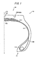
Fig. 1 is a sectional view in the tire radial direction of a pneumatic tire according one embodiment of the present invention. -
Fig. 2 is a developed plane view showing a tread pattern of a pneumatic tire according to one embodiment of the present invention. -
Fig. 3 is a sectional view taken along the arrow 3-3 ofFig. 2 . -
Fig. 4 is a sectional view taken along the arrow 4-4 ofFig. 2 . -
Fig. 5 is a sectional view taken along the arrow 5-5 ofFig. 2 . -
Fig. 6 is a plane view showing a tread pattern of one example of a conventional pneumatic tire. -
Fig. 7 is a plane view showing a tread pattern of another example of a conventional pneumatic tire. -
- 10 pneumatic tire
- 18 tread portion
- 20 center main groove (main groove)
- 22L shoulder main groove (main groove)
- 22R shoulder main groove (main groove)
- 24 flexion portion (bending portion)
- 26 linear portion (main groove portion)
- 28 projection for preventing stone trapping
- 26W groove wall
- 70 center main groove
- 76 linear portion (main groove portion)
- 80 center main groove (main groove)
- 86 linear portion (main groove portion)
- CL tire equator plane
- N tread normal line direction
- θ1 groove wall angle
- θ2 groove wall angle
- W groove width
- U tire circumferential direction
- Hereinafter, embodiments of the present invention will be discussed. As shown in
Fig. 1 , apneumatic tire 10 according one embodiment of the present invention is a tire for truck and bus and has acarcass 12. Thecarcass 12 has turn-upportions 12E formed by turning up both end portions aroundbead core 11C ofbead portions 11. -
Belts 14 are embedded radially outside of acrown portion 12C of thecarcass 12. A tread portion 18 (see alsoFig. 2 ) provided with grooves is arranged radially outside of thebelts 14. - As shown in
Fig. 2 , formed on thetread portion 18 are a centermain groove 20 extending on the tire equator plane CL along the tire circumference direction U in a zigzag shape, shouldermain grooves land portion rows land portion rows tread portion 18. - In the inner
land portion row 30L, there are formedinner lug grooves 34L which extend from bent concave portions 32L in the center main groove side formed by the centermain groove 20 and which terminate within the land portion row andouter lug groove 38L which extend from bentconcave portions 36L in the shoulder main groove side formed by the shouldermain groove 22L and which terminate within the land portion. Likewise, in the innerland portion row 30R, there are formedinner lug grooves 34R which extend from bentconcave portions 32R in the center main groove side formed by the centermain groove 20 and which terminate within the land portion row andouter lug groove 38R which extend from bentconcave portions 3 6R in the shoulder main groove side formed by the shouldermain groove 22R and which terminate within the land portion. - Further, in the inner
land portion row 30L, there are formed inner first sipes 44L which extend from bent convex portions 42L in the center main groove side formed by the centermain groove 20 and which terminate within the land portion row; inner second sipes 46L which extend from near bent concave portion 32L in the center main groove and which terminate within the land portion; andouter sipes 48L which extend from the bentconcave portion 36L and terminate within the land portion. Likewise, in the innerland portion row 30R, there are formed inner first sipes 44R which extend from bent convex portions 42R in the center main groove side formed by the centermain groove 20 and which terminate within the land portion row; innersecond sipes 46R which extend from near bentconcave portion 32R in the center main groove and which terminate within the land portion; andouter sipes 48R which extend from the bentconcave portion 36R and terminate within the land portion. - A plurality of
lug grooves 52 crossing the tire circumference direction U are formed in the outerland portion rows lug groove 52 extends beyond the tread end T to be able to drain water to the outer side in the tire width direction. In this specification, the term "tread end" refers to an outermost part of a ground contacting area in the tire width direction under a condition where a pneumatic tire is mounted on a standard rim specified in JATMA YEAR BOOK (2006 Edition, Japan Automobile Tire Manufacturers Association Standards), 100% of air pressure (maximum air pressure) corresponding to the maximum load capacity at applied size and ply rating defined in JATMA YEAR BOOK (load indicated in bold characters in the internal pressure-load capacity correspondence table) is filled as internal pressure, and then the maximum load capacity is applied. It is noted that where the TRA standard or the ETRTO standard is effective in the place of use or manufacturing, the above-mentioned definition follows such standard - The center
main groove 20 consists of flexion portions (bending portions) 24 bending in a zigzag shape and linear main groove portions (hereinafter referred to as linear portions) 26 connecting flexion portions adjacent in the tire circumference direction U. In this embodiment, the projections for preventing stone trapping (stone ejectors) 28 are disposed only on the groove bottoms of theflexion portions 24. This can significantly reduce the number of projections for preventing stone trapping to be disposed as compared with the conventional tire to thereby remarkably decrease likelihood of appearing the projections for preventing stone trapping on the tire surface while the tire is still usable. - Furthermore, in this embodiment, the projections preventing stone trapping are disposed only on the
flexion portions 24 of thecenter groove 20 where stone trapping most likely occurs to ensure the durability of thecenter groove 20, but not disposed in the shouldermain grooves projection 28 for preventing stone trapping to be arranged is minimized, so that there is remarkably decreased likelihood of appearing the projection for preventing stone trapping on the tire surface while the tire is still usable. This does not give the user an impression of early worn-out and can improve the user's impression that the tire is completely used. - It is noted that the height J (see
Fig. 3 ) of theprojections 28 for preventing stone trapping in this embodiment is within a range of 5% to 50% of the groove depth of thecenter groove 20. Due to this, a stone is difficult to be trapped between the wall surface (groove wall 24W inFig. 3 ) and theprojection 28 for preventing stone trapping. - As shown in
Figs. 4 and 5 , the groove wall angle θ (θ1 inFig. 4 and θ2 inFig. 5 ) of thegroove wall 26W of thelinear portion 26 with respect to the tread normal line direction N gradually varies (fluctuate) within a range D of 2.0 mm from the end of theflexion portion 24 along the linear portion 26 (a section of a linear portion). That is, the angle θ gradually increase from the end of theflexion potion 24. This makes it difficult to cause stone trapping at the fluctuating section of the linear portion and its neighbors. It is noted that in this embodiment, the both ends of theprojection 28 for preventing stone trapping are at the both end portions of theflexion portion 24, so the wall groove angle θ fluctuates within 2.0 mm from the end portion of theprojection 28 for preventing stone trapping. - Further, the groove wall angle θ of the
groove wall 26W of thelinear portion 26 with respect to the tread normal line direction N is within a range of 15 degrees to 18 degrees, which is larger than the groove wall angle α of thegroove wall 24W of theflexion portion 24 with respect to the tread normal line direction N. This enlarges the groove width of thelinear portion 26 modestly to enable a further improvement of the stone-trapping resistance. - Meanwhile, the
flexion portion 24 has a dogleg shape where stress tends to concentrate. The present embodiment, however, makes the groove wall angle θ of thegroove wall 24W of theflexion portion 24 with respect to the tread normal line direction N smaller than the groove wall angle θ of thegroove wall 26W of thelinear portion 26 with respect to the tread normal line direction N, so that the radius of curvature of the groove bottom of theflexion portion 24 is not necessarily small even if the groove width of theflexion portion 24 is not widen. This gives the same level of crack resistance at the groove bottom of theflexion portion 24 as that of the conventional tire. - In addition, a ratio of the groove width W of the
linear portion 26 on the tread surface to the groove depth h (W/h) is within a range of 0.8 to 1.2., which provide thelinear portion 26 with a shape with less likelihood of stone trapping. - Both of the end portions of the
projection 28 for preventing stone trapping are rounded with, for example, so-called single R to give a shape which hardly causes damage such as chipping. - In order to confirm the result of the present invention, the present inventor prepared one example of the
pneumatic tire 10 of the above embodiment (herein after referred to as Example Tire) and two examples of conventional pneumatic tire (hereinafter referred to as Conventional Tire 1 and Conventional Tire 2), and also measured the amount of ware during the field test for each tire to evaluate the stone-trapping resistance and tire operation life. - In this test, Conventional Tire 1 had a center
main groove 70 without aprojection 28 for preventing stone trapping, and an angle of the groove wall (groove wall angle) of thelinear portion 76 constituting the centermain groove 70 with respect to the tread normal line direction smaller than that of Example Tire, as shown inFig. 6 . Conventional Tire 2 was similar to the pneumatic tire disclosed in Patent Document 1. It hadprojections 88 for preventing stone trapping in a linear portion which were arranged in a line along thelinear portion 86 on the bottom portions of thelinear portions 86 constituting the centermain groove 80, and an angle of the groove wall (groove wall angle) of thelinear portion 86 with respect to the tread normal line direction smaller than that of Example Tire, as shown inFig. 7 . - It is noted that in Example Tire, the
projection 28 for preventing stone trapping had a shape bending along theflexion portion 24 and was sized to extend L = 4 mm from the center of bending toward the respective end portions along the groove. As shown inFig. 5 , the groove shape of thelinear portion 26 at the central portion in the longitudinal direction was such that groove depth h: groove width W equaled to 5:4 and W/h was 0.8, as shown inFig. 5 . - In this test, all the tire were for truck and bus and had a tire size of 11R22.5. In this test, each tire was mounted on a regular rim, and then installed on a drive shaft of a vehicle (2D4) with a regular load and a regular internal pressure being applied to. The term "regular rim" as used herein refers to a standard rim for an applied size specified in, for example, YEAR BOOK 2006 Edition published by JATMA, and the terms "regular load" and "regular internal pressure" refer to a maximum load capacity and an air pressure for this maximum load at applied size and ply rating defined in YEAR BOOK 2006 Edition published by JATMA as well.
- Thereafter, the tires were driven on off roads and average numbers of stones trapped in the center main groove (average stone-trapping numbers) were measured for the tires installed on the F shaft.
- In this test, the installation positions of the tires on the vehicle were fixed, but the tires were swapped between the test vehicles. The measurements were conducted every 15,000 km in total of five times. The results are shown in Table 1.
- [Table 1]
Measurement Total number of
stone trapping1 2 3 4 5 Conventional Tire 1 15 11 9 6 3 44 Conventional Tire 2 0 0 0 0 0 0 Example Tire 0 1 1 0 0 2 - As can be seen from Table 1, the total number of stone trapping over five measurements was 44 for Conventional Tire 1, and 0 for Conventional Tire 2. Meanwhile, the total number of stone trapping was 2 for Example Tire, which proves that Example Tire has the same level of stone-trapping resistance as that of Conventional Tire 2.
- The inventor also mounted each of Example Tire, Conventional Tire 1 and Conventional Tire 2 on a regular rim, and then installed it on a drive shaft of a vehicle (2D4) with a regular load and a regular internal pressure being applied to. Thereafter, the tire was practically used, and when the user judged the rubber portion of the tire equator plan CL as being completely wom out, the groove depth of the remaining shoulder main groove was measured. In this test again, the installation positions of the tires on the vehicle were fixed, but the tires were swapped between the test vehicles. Measurements were conducted five times and the averages of measured values were used as remaining groove depths. The remaining groove depths of the tires are shown in Table 2.
- [Table 2]
Remaining groove depth
of shoulder main grooveConventional Tire 1 2.1 mm Conventional Tire 2 5.0 mm Example Tire 2.9 mm - As can be seen from Table 2, the remaining groove depth of the shoulder
main grooves Fig. 6 ) was 2.1 mm in Conventional Tire 1, and the remaining groove depth of the shouldermain grooves Fig. 7 ) was 5.0 mm in Conventional Tire 2. Meanwhile, the remaining groove depth of the shouldermain grooves - It is noted that the present embodiment arranges
projections 28 for preventing stone trapping only in theflexion portions 24 of the centermain groove 20, but the projections for preventing stone trapping may be arranged in the shouldermain grooves main groove 20. - Although the present invention has been described above with reference to a preferred embodiment, it is apparent that the embodiment is merely an example and various modifications may be made without departing from the scope of the invention as defined in the claims. Needless to say, the scope of the present invention is not limited to the above-described embodiment.
Claims (4)
- A pneumatic tire provided with a plurality of main grooves (20) extending along a tire circumference direction in a zigzag manner on a tread portion, wherein projections (28) for preventing stone trapping are disposed on a groove bottom only of a bending portion (24) of at least a main groove (20) closest to a tire equator plane where the main groove bends in a zigzag manner, characterized in that an angle (θ) of a groove wall of a main groove portion connecting the adjacent bending portions (24) with respect to a tread normal line direction is larger than an angle (α) of a groove wall of the bending portion (24) with respect to the tread normal line direction.
- The pneumatic tire according to claim 1, wherein the angle (θ) of the groove wall of the main groove portion with respect to the tread normal line direction is within a range of 15 degrees to 20 degrees.
- The pneumatic tire according to claim 1 or 2, wherein a ratio w/h of a groove width W of the main groove portion on the tread surface to a groove depth h of the main groove portion is within a range of 0.8 to 1.2.
- The pneumatic tire according to any one of claims 1 to 3, wherein the angle (θ) of the groove wall of the main groove portion with respect to the tread normal line direction varies within a range of 2.0 mm from the bending portion (24) along the main groove portion.
Applications Claiming Priority (2)
| Application Number | Priority Date | Filing Date | Title |
|---|---|---|---|
| JP2007019741A JP4838162B2 (en) | 2007-01-30 | 2007-01-30 | Pneumatic tire |
| PCT/JP2007/074672 WO2008093481A1 (en) | 2007-01-30 | 2007-12-21 | Pneumatic tire |
Publications (3)
| Publication Number | Publication Date |
|---|---|
| EP2116397A1 EP2116397A1 (en) | 2009-11-11 |
| EP2116397A4 EP2116397A4 (en) | 2010-10-06 |
| EP2116397B1 true EP2116397B1 (en) | 2011-11-02 |
Family
ID=39673796
Family Applications (1)
| Application Number | Title | Priority Date | Filing Date |
|---|---|---|---|
| EP07859952A Not-in-force EP2116397B1 (en) | 2007-01-30 | 2007-12-21 | Pneumatic tire |
Country Status (7)
| Country | Link |
|---|---|
| US (1) | US8408260B2 (en) |
| EP (1) | EP2116397B1 (en) |
| JP (1) | JP4838162B2 (en) |
| CN (1) | CN101595003B (en) |
| AT (1) | ATE531535T1 (en) |
| BR (1) | BRPI0721358B1 (en) |
| WO (1) | WO2008093481A1 (en) |
Families Citing this family (18)
| Publication number | Priority date | Publication date | Assignee | Title |
|---|---|---|---|---|
| WO2013015408A1 (en) * | 2011-07-27 | 2013-01-31 | 株式会社ブリヂストン | Tyre |
| CN105073450B (en) | 2012-12-21 | 2017-06-13 | 倍耐力轮胎股份公司 | For the tire of heavy-duty vehicle wheel |
| JP5732089B2 (en) * | 2013-02-26 | 2015-06-10 | 住友ゴム工業株式会社 | Pneumatic tire |
| CN103350617B (en) * | 2013-07-25 | 2016-03-02 | 厦门正新橡胶工业有限公司 | Tread structure of radial tyre |
| JP5820442B2 (en) * | 2013-08-23 | 2015-11-24 | 株式会社ブリヂストン | Pneumatic tire |
| JP2017501082A (en) | 2013-12-26 | 2017-01-12 | ブリヂストン アメリカズ タイヤ オペレーションズ、 エルエルシー | Tire tread with flexible gate device |
| EP3102439B1 (en) | 2014-02-04 | 2020-02-19 | Bridgestone Americas Tire Operations, LLC | Radial stone ejectors |
| US20160332491A1 (en) * | 2014-02-04 | 2016-11-17 | Bridgestone Americas Tire Operations, Llc | Rounded stone ejectors |
| JP6603471B2 (en) * | 2015-04-10 | 2019-11-06 | 株式会社ブリヂストン | tire |
| JP2017024662A (en) * | 2015-07-27 | 2017-02-02 | 横浜ゴム株式会社 | Pneumatic tire |
| CN106042788A (en) * | 2016-08-03 | 2016-10-26 | 厦门正新海燕轮胎有限公司 | Stone-clamping-proof tire |
| EP3505368B1 (en) * | 2016-08-26 | 2020-09-30 | Bridgestone Corporation | Tire |
| EP3323637B1 (en) * | 2016-11-22 | 2019-09-04 | Sumitomo Rubber Industries, Ltd. | Tire |
| JP6926679B2 (en) * | 2017-05-29 | 2021-08-25 | 住友ゴム工業株式会社 | tire |
| JP6907758B2 (en) * | 2017-06-28 | 2021-07-21 | 住友ゴム工業株式会社 | tire |
| CN111516435A (en) * | 2020-05-15 | 2020-08-11 | 吉利汽车研究院(宁波)有限公司 | Stone clamping prevention tire and vehicle |
| JP7156337B2 (en) * | 2020-06-16 | 2022-10-19 | 住友ゴム工業株式会社 | tire |
| CN116714395B (en) * | 2023-06-30 | 2026-03-03 | 山东玲珑橡胶科技有限公司 | Tire suitable for long-distance transportation of complex road conditions |
Family Cites Families (12)
| Publication number | Priority date | Publication date | Assignee | Title |
|---|---|---|---|---|
| FR2050653A5 (en) * | 1969-06-19 | 1971-04-02 | Michelin & Cie | |
| JPS595443B2 (en) * | 1979-11-29 | 1984-02-04 | 株式会社ブリヂストン | Pneumatic tires for heavy loads |
| JPS59172005A (en) * | 1983-03-22 | 1984-09-28 | Mitsubishi Electric Corp | Numerical controller |
| JPS59172005U (en) | 1983-05-06 | 1984-11-17 | 住友ゴム工業株式会社 | Tire tread that suppresses uneven wear and stone build-up |
| JPS60189608A (en) * | 1984-03-09 | 1985-09-27 | Yokohama Rubber Co Ltd:The | Pneumatic tire |
| JPH0662042B2 (en) * | 1986-02-22 | 1994-08-17 | 住友ゴム工業株式会社 | Pneumatic tires for heavy vehicles |
| JPH04306105A (en) * | 1991-04-02 | 1992-10-28 | Bridgestone Corp | Pneumatic tire |
| JP3076089B2 (en) * | 1991-06-25 | 2000-08-14 | 株式会社ブリヂストン | Heavy duty pneumatic tires |
| JPH10151914A (en) * | 1996-11-21 | 1998-06-09 | Yokohama Rubber Co Ltd:The | Pneumatic radial tire for heavy load |
| JP2001030717A (en) | 1999-07-23 | 2001-02-06 | Bridgestone Corp | Pneumatic tire |
| JP2004034771A (en) * | 2002-07-01 | 2004-02-05 | Yokohama Rubber Co Ltd:The | Pneumatic radial tire |
| JP4626386B2 (en) * | 2005-05-11 | 2011-02-09 | 横浜ゴム株式会社 | Pneumatic tire |
-
2007
- 2007-01-30 JP JP2007019741A patent/JP4838162B2/en not_active Expired - Fee Related
- 2007-12-21 AT AT07859952T patent/ATE531535T1/en active
- 2007-12-21 EP EP07859952A patent/EP2116397B1/en not_active Not-in-force
- 2007-12-21 US US12/524,954 patent/US8408260B2/en not_active Expired - Fee Related
- 2007-12-21 WO PCT/JP2007/074672 patent/WO2008093481A1/en not_active Ceased
- 2007-12-21 BR BRPI0721358-1A patent/BRPI0721358B1/en not_active IP Right Cessation
- 2007-12-21 CN CN2007800507033A patent/CN101595003B/en not_active Expired - Fee Related
Also Published As
| Publication number | Publication date |
|---|---|
| BRPI0721358A2 (en) | 2014-02-25 |
| EP2116397A4 (en) | 2010-10-06 |
| EP2116397A1 (en) | 2009-11-11 |
| CN101595003A (en) | 2009-12-02 |
| ATE531535T1 (en) | 2011-11-15 |
| BRPI0721358B1 (en) | 2019-10-08 |
| US8408260B2 (en) | 2013-04-02 |
| US20100139827A1 (en) | 2010-06-10 |
| JP4838162B2 (en) | 2011-12-14 |
| CN101595003B (en) | 2012-10-31 |
| WO2008093481A1 (en) | 2008-08-07 |
| JP2008184053A (en) | 2008-08-14 |
Similar Documents
| Publication | Publication Date | Title |
|---|---|---|
| EP2116397B1 (en) | Pneumatic tire | |
| CN108136853B (en) | Pneumatic tire | |
| CN105377587B (en) | Heavy Duty Tires | |
| CN101687441B (en) | Pneumatic tire | |
| AU2015329071B2 (en) | Pneumatic tire | |
| CN104955659B (en) | Pneumatic tire | |
| CN107709047B (en) | Pneumatic tires | |
| JP6720551B2 (en) | Pneumatic tire | |
| AU2016210113B2 (en) | Pneumatic tire | |
| US9902208B2 (en) | Pneumatic tire | |
| US12515479B2 (en) | Tire | |
| US11383559B2 (en) | Pneumatic tire | |
| CN100478196C (en) | Pneumatic tire | |
| JP7290066B2 (en) | tire | |
| CN115379957B (en) | tire | |
| CN112689566A (en) | Pneumatic tire | |
| US8162015B2 (en) | Pneumatic tire having asymmetrical tread pattern | |
| US20210008928A1 (en) | Pneumatic Tire | |
| CN108602389B (en) | Pneumatic tires | |
| US20170253087A1 (en) | Pneumatic tire | |
| CN112384376B (en) | pneumatic tires | |
| CN114007876A (en) | Pneumatic tire | |
| CN119159930A (en) | Tires and Tire Treads | |
| CN115103777B (en) | Tyre for vehicle wheels | |
| WO2025057874A1 (en) | Tire |
Legal Events
| Date | Code | Title | Description |
|---|---|---|---|
| PUAI | Public reference made under article 153(3) epc to a published international application that has entered the european phase |
Free format text: ORIGINAL CODE: 0009012 |
|
| 17P | Request for examination filed |
Effective date: 20090731 |
|
| AK | Designated contracting states |
Kind code of ref document: A1 Designated state(s): AT BE BG CH CY CZ DE DK EE ES FI FR GB GR HU IE IS IT LI LT LU LV MC MT NL PL PT RO SE SI SK TR |
|
| DAX | Request for extension of the european patent (deleted) | ||
| A4 | Supplementary search report drawn up and despatched |
Effective date: 20100906 |
|
| RIC1 | Information provided on ipc code assigned before grant |
Ipc: B60C 11/13 20060101ALI20110324BHEP Ipc: B60C 11/04 20060101AFI20110324BHEP |
|
| GRAP | Despatch of communication of intention to grant a patent |
Free format text: ORIGINAL CODE: EPIDOSNIGR1 |
|
| GRAS | Grant fee paid |
Free format text: ORIGINAL CODE: EPIDOSNIGR3 |
|
| GRAA | (expected) grant |
Free format text: ORIGINAL CODE: 0009210 |
|
| AK | Designated contracting states |
Kind code of ref document: B1 Designated state(s): AT BE BG CH CY CZ DE DK EE ES FI FR GB GR HU IE IS IT LI LT LU LV MC MT NL PL PT RO SE SI SK TR |
|
| REG | Reference to a national code |
Ref country code: GB Ref legal event code: FG4D |
|
| REG | Reference to a national code |
Ref country code: CH Ref legal event code: EP |
|
| REG | Reference to a national code |
Ref country code: IE Ref legal event code: FG4D |
|
| REG | Reference to a national code |
Ref country code: DE Ref legal event code: R096 Ref document number: 602007018525 Country of ref document: DE Effective date: 20120126 |
|
| REG | Reference to a national code |
Ref country code: NL Ref legal event code: VDEP Effective date: 20111102 |
|
| LTIE | Lt: invalidation of european patent or patent extension |
Effective date: 20111102 |
|
| PG25 | Lapsed in a contracting state [announced via postgrant information from national office to epo] |
Ref country code: IS Free format text: LAPSE BECAUSE OF FAILURE TO SUBMIT A TRANSLATION OF THE DESCRIPTION OR TO PAY THE FEE WITHIN THE PRESCRIBED TIME-LIMIT Effective date: 20120302 Ref country code: LT Free format text: LAPSE BECAUSE OF FAILURE TO SUBMIT A TRANSLATION OF THE DESCRIPTION OR TO PAY THE FEE WITHIN THE PRESCRIBED TIME-LIMIT Effective date: 20111102 |
|
| PG25 | Lapsed in a contracting state [announced via postgrant information from national office to epo] |
Ref country code: NL Free format text: LAPSE BECAUSE OF FAILURE TO SUBMIT A TRANSLATION OF THE DESCRIPTION OR TO PAY THE FEE WITHIN THE PRESCRIBED TIME-LIMIT Effective date: 20111102 Ref country code: LV Free format text: LAPSE BECAUSE OF FAILURE TO SUBMIT A TRANSLATION OF THE DESCRIPTION OR TO PAY THE FEE WITHIN THE PRESCRIBED TIME-LIMIT Effective date: 20111102 Ref country code: PL Free format text: LAPSE BECAUSE OF FAILURE TO SUBMIT A TRANSLATION OF THE DESCRIPTION OR TO PAY THE FEE WITHIN THE PRESCRIBED TIME-LIMIT Effective date: 20111102 Ref country code: BE Free format text: LAPSE BECAUSE OF FAILURE TO SUBMIT A TRANSLATION OF THE DESCRIPTION OR TO PAY THE FEE WITHIN THE PRESCRIBED TIME-LIMIT Effective date: 20111102 Ref country code: PT Free format text: LAPSE BECAUSE OF FAILURE TO SUBMIT A TRANSLATION OF THE DESCRIPTION OR TO PAY THE FEE WITHIN THE PRESCRIBED TIME-LIMIT Effective date: 20120302 Ref country code: SE Free format text: LAPSE BECAUSE OF FAILURE TO SUBMIT A TRANSLATION OF THE DESCRIPTION OR TO PAY THE FEE WITHIN THE PRESCRIBED TIME-LIMIT Effective date: 20111102 Ref country code: GR Free format text: LAPSE BECAUSE OF FAILURE TO SUBMIT A TRANSLATION OF THE DESCRIPTION OR TO PAY THE FEE WITHIN THE PRESCRIBED TIME-LIMIT Effective date: 20120203 Ref country code: SI Free format text: LAPSE BECAUSE OF FAILURE TO SUBMIT A TRANSLATION OF THE DESCRIPTION OR TO PAY THE FEE WITHIN THE PRESCRIBED TIME-LIMIT Effective date: 20111102 |
|
| PG25 | Lapsed in a contracting state [announced via postgrant information from national office to epo] |
Ref country code: CY Free format text: LAPSE BECAUSE OF FAILURE TO SUBMIT A TRANSLATION OF THE DESCRIPTION OR TO PAY THE FEE WITHIN THE PRESCRIBED TIME-LIMIT Effective date: 20111102 |
|
| PG25 | Lapsed in a contracting state [announced via postgrant information from national office to epo] |
Ref country code: BG Free format text: LAPSE BECAUSE OF FAILURE TO SUBMIT A TRANSLATION OF THE DESCRIPTION OR TO PAY THE FEE WITHIN THE PRESCRIBED TIME-LIMIT Effective date: 20120202 Ref country code: CZ Free format text: LAPSE BECAUSE OF FAILURE TO SUBMIT A TRANSLATION OF THE DESCRIPTION OR TO PAY THE FEE WITHIN THE PRESCRIBED TIME-LIMIT Effective date: 20111102 Ref country code: SK Free format text: LAPSE BECAUSE OF FAILURE TO SUBMIT A TRANSLATION OF THE DESCRIPTION OR TO PAY THE FEE WITHIN THE PRESCRIBED TIME-LIMIT Effective date: 20111102 Ref country code: DK Free format text: LAPSE BECAUSE OF FAILURE TO SUBMIT A TRANSLATION OF THE DESCRIPTION OR TO PAY THE FEE WITHIN THE PRESCRIBED TIME-LIMIT Effective date: 20111102 Ref country code: MC Free format text: LAPSE BECAUSE OF NON-PAYMENT OF DUE FEES Effective date: 20111231 Ref country code: EE Free format text: LAPSE BECAUSE OF FAILURE TO SUBMIT A TRANSLATION OF THE DESCRIPTION OR TO PAY THE FEE WITHIN THE PRESCRIBED TIME-LIMIT Effective date: 20111102 |
|
| REG | Reference to a national code |
Ref country code: CH Ref legal event code: PL |
|
| PG25 | Lapsed in a contracting state [announced via postgrant information from national office to epo] |
Ref country code: RO Free format text: LAPSE BECAUSE OF FAILURE TO SUBMIT A TRANSLATION OF THE DESCRIPTION OR TO PAY THE FEE WITHIN THE PRESCRIBED TIME-LIMIT Effective date: 20111102 |
|
| PLBE | No opposition filed within time limit |
Free format text: ORIGINAL CODE: 0009261 |
|
| STAA | Information on the status of an ep patent application or granted ep patent |
Free format text: STATUS: NO OPPOSITION FILED WITHIN TIME LIMIT |
|
| REG | Reference to a national code |
Ref country code: AT Ref legal event code: MK05 Ref document number: 531535 Country of ref document: AT Kind code of ref document: T Effective date: 20111102 |
|
| REG | Reference to a national code |
Ref country code: IE Ref legal event code: MM4A |
|
| 26N | No opposition filed |
Effective date: 20120803 |
|
| PG25 | Lapsed in a contracting state [announced via postgrant information from national office to epo] |
Ref country code: LI Free format text: LAPSE BECAUSE OF NON-PAYMENT OF DUE FEES Effective date: 20111231 Ref country code: IE Free format text: LAPSE BECAUSE OF NON-PAYMENT OF DUE FEES Effective date: 20111221 Ref country code: CH Free format text: LAPSE BECAUSE OF NON-PAYMENT OF DUE FEES Effective date: 20111231 |
|
| REG | Reference to a national code |
Ref country code: DE Ref legal event code: R097 Ref document number: 602007018525 Country of ref document: DE Effective date: 20120803 |
|
| PG25 | Lapsed in a contracting state [announced via postgrant information from national office to epo] |
Ref country code: AT Free format text: LAPSE BECAUSE OF FAILURE TO SUBMIT A TRANSLATION OF THE DESCRIPTION OR TO PAY THE FEE WITHIN THE PRESCRIBED TIME-LIMIT Effective date: 20111102 |
|
| PG25 | Lapsed in a contracting state [announced via postgrant information from national office to epo] |
Ref country code: MT Free format text: LAPSE BECAUSE OF FAILURE TO SUBMIT A TRANSLATION OF THE DESCRIPTION OR TO PAY THE FEE WITHIN THE PRESCRIBED TIME-LIMIT Effective date: 20111102 |
|
| PGFP | Annual fee paid to national office [announced via postgrant information from national office to epo] |
Ref country code: GB Payment date: 20121219 Year of fee payment: 6 Ref country code: IT Payment date: 20121218 Year of fee payment: 6 |
|
| PGFP | Annual fee paid to national office [announced via postgrant information from national office to epo] |
Ref country code: FR Payment date: 20130107 Year of fee payment: 6 |
|
| PG25 | Lapsed in a contracting state [announced via postgrant information from national office to epo] |
Ref country code: ES Free format text: LAPSE BECAUSE OF FAILURE TO SUBMIT A TRANSLATION OF THE DESCRIPTION OR TO PAY THE FEE WITHIN THE PRESCRIBED TIME-LIMIT Effective date: 20120213 |
|
| PGFP | Annual fee paid to national office [announced via postgrant information from national office to epo] |
Ref country code: DE Payment date: 20121219 Year of fee payment: 6 |
|
| PG25 | Lapsed in a contracting state [announced via postgrant information from national office to epo] |
Ref country code: LU Free format text: LAPSE BECAUSE OF NON-PAYMENT OF DUE FEES Effective date: 20111221 |
|
| PG25 | Lapsed in a contracting state [announced via postgrant information from national office to epo] |
Ref country code: FI Free format text: LAPSE BECAUSE OF FAILURE TO SUBMIT A TRANSLATION OF THE DESCRIPTION OR TO PAY THE FEE WITHIN THE PRESCRIBED TIME-LIMIT Effective date: 20111102 |
|
| PG25 | Lapsed in a contracting state [announced via postgrant information from national office to epo] |
Ref country code: TR Free format text: LAPSE BECAUSE OF FAILURE TO SUBMIT A TRANSLATION OF THE DESCRIPTION OR TO PAY THE FEE WITHIN THE PRESCRIBED TIME-LIMIT Effective date: 20111102 |
|
| PG25 | Lapsed in a contracting state [announced via postgrant information from national office to epo] |
Ref country code: HU Free format text: LAPSE BECAUSE OF FAILURE TO SUBMIT A TRANSLATION OF THE DESCRIPTION OR TO PAY THE FEE WITHIN THE PRESCRIBED TIME-LIMIT Effective date: 20111102 |
|
| REG | Reference to a national code |
Ref country code: DE Ref legal event code: R119 Ref document number: 602007018525 Country of ref document: DE |
|
| GBPC | Gb: european patent ceased through non-payment of renewal fee |
Effective date: 20131221 |
|
| REG | Reference to a national code |
Ref country code: FR Ref legal event code: ST Effective date: 20140829 |
|
| REG | Reference to a national code |
Ref country code: DE Ref legal event code: R119 Ref document number: 602007018525 Country of ref document: DE Effective date: 20140701 |
|
| PG25 | Lapsed in a contracting state [announced via postgrant information from national office to epo] |
Ref country code: DE Free format text: LAPSE BECAUSE OF NON-PAYMENT OF DUE FEES Effective date: 20140701 |
|
| PG25 | Lapsed in a contracting state [announced via postgrant information from national office to epo] |
Ref country code: GB Free format text: LAPSE BECAUSE OF NON-PAYMENT OF DUE FEES Effective date: 20131221 Ref country code: FR Free format text: LAPSE BECAUSE OF NON-PAYMENT OF DUE FEES Effective date: 20131231 |
|
| PG25 | Lapsed in a contracting state [announced via postgrant information from national office to epo] |
Ref country code: IT Free format text: LAPSE BECAUSE OF NON-PAYMENT OF DUE FEES Effective date: 20131231 |
|
| PG25 | Lapsed in a contracting state [announced via postgrant information from national office to epo] |
Ref country code: IT Free format text: LAPSE BECAUSE OF NON-PAYMENT OF DUE FEES Effective date: 20131221 |