EP2953583B1 - Augmentation tibiale conique - Google Patents
Augmentation tibiale conique Download PDFInfo
- Publication number
- EP2953583B1 EP2953583B1 EP14706397.8A EP14706397A EP2953583B1 EP 2953583 B1 EP2953583 B1 EP 2953583B1 EP 14706397 A EP14706397 A EP 14706397A EP 2953583 B1 EP2953583 B1 EP 2953583B1
- Authority
- EP
- European Patent Office
- Prior art keywords
- tibial
- augment
- taper
- medial
- lateral
- Prior art date
- Legal status (The legal status is an assumption and is not a legal conclusion. Google has not performed a legal analysis and makes no representation as to the accuracy of the status listed.)
- Active
Links
- 210000000988 bone and bone Anatomy 0.000 claims description 28
- 210000003127 knee Anatomy 0.000 claims description 14
- 239000007943 implant Substances 0.000 claims description 8
- 230000003190 augmentative effect Effects 0.000 claims description 2
- 210000002303 tibia Anatomy 0.000 description 26
- 238000001356 surgical procedure Methods 0.000 description 10
- 238000007373 indentation Methods 0.000 description 4
- 125000006850 spacer group Chemical group 0.000 description 4
- 210000000689 upper leg Anatomy 0.000 description 4
- 230000006378 damage Effects 0.000 description 3
- 210000000629 knee joint Anatomy 0.000 description 3
- 238000002271 resection Methods 0.000 description 3
- 239000000203 mixture Substances 0.000 description 2
- 208000027418 Wounds and injury Diseases 0.000 description 1
- 230000003416 augmentation Effects 0.000 description 1
- 239000004568 cement Substances 0.000 description 1
- 230000007850 degeneration Effects 0.000 description 1
- 201000010099 disease Diseases 0.000 description 1
- 208000037265 diseases, disorders, signs and symptoms Diseases 0.000 description 1
- 238000009472 formulation Methods 0.000 description 1
- 208000014674 injury Diseases 0.000 description 1
- 238000013150 knee replacement Methods 0.000 description 1
- 239000000463 material Substances 0.000 description 1
- 238000005259 measurement Methods 0.000 description 1
- 238000000034 method Methods 0.000 description 1
- 230000009528 severe injury Effects 0.000 description 1
- 210000001694 thigh bone Anatomy 0.000 description 1
Images


Classifications
-
- A—HUMAN NECESSITIES
- A61—MEDICAL OR VETERINARY SCIENCE; HYGIENE
- A61F—FILTERS IMPLANTABLE INTO BLOOD VESSELS; PROSTHESES; DEVICES PROVIDING PATENCY TO, OR PREVENTING COLLAPSING OF, TUBULAR STRUCTURES OF THE BODY, e.g. STENTS; ORTHOPAEDIC, NURSING OR CONTRACEPTIVE DEVICES; FOMENTATION; TREATMENT OR PROTECTION OF EYES OR EARS; BANDAGES, DRESSINGS OR ABSORBENT PADS; FIRST-AID KITS
- A61F2/00—Filters implantable into blood vessels; Prostheses, i.e. artificial substitutes or replacements for parts of the body; Appliances for connecting them with the body; Devices providing patency to, or preventing collapsing of, tubular structures of the body, e.g. stents
- A61F2/02—Prostheses implantable into the body
- A61F2/30—Joints
- A61F2/38—Joints for elbows or knees
- A61F2/389—Tibial components
-
- A—HUMAN NECESSITIES
- A61—MEDICAL OR VETERINARY SCIENCE; HYGIENE
- A61F—FILTERS IMPLANTABLE INTO BLOOD VESSELS; PROSTHESES; DEVICES PROVIDING PATENCY TO, OR PREVENTING COLLAPSING OF, TUBULAR STRUCTURES OF THE BODY, e.g. STENTS; ORTHOPAEDIC, NURSING OR CONTRACEPTIVE DEVICES; FOMENTATION; TREATMENT OR PROTECTION OF EYES OR EARS; BANDAGES, DRESSINGS OR ABSORBENT PADS; FIRST-AID KITS
- A61F2/00—Filters implantable into blood vessels; Prostheses, i.e. artificial substitutes or replacements for parts of the body; Appliances for connecting them with the body; Devices providing patency to, or preventing collapsing of, tubular structures of the body, e.g. stents
- A61F2/02—Prostheses implantable into the body
- A61F2/30—Joints
- A61F2/30721—Accessories
- A61F2/30734—Modular inserts, sleeves or augments, e.g. placed on proximal part of stem for fixation purposes or wedges for bridging a bone defect
-
- A—HUMAN NECESSITIES
- A61—MEDICAL OR VETERINARY SCIENCE; HYGIENE
- A61F—FILTERS IMPLANTABLE INTO BLOOD VESSELS; PROSTHESES; DEVICES PROVIDING PATENCY TO, OR PREVENTING COLLAPSING OF, TUBULAR STRUCTURES OF THE BODY, e.g. STENTS; ORTHOPAEDIC, NURSING OR CONTRACEPTIVE DEVICES; FOMENTATION; TREATMENT OR PROTECTION OF EYES OR EARS; BANDAGES, DRESSINGS OR ABSORBENT PADS; FIRST-AID KITS
- A61F2/00—Filters implantable into blood vessels; Prostheses, i.e. artificial substitutes or replacements for parts of the body; Appliances for connecting them with the body; Devices providing patency to, or preventing collapsing of, tubular structures of the body, e.g. stents
- A61F2/02—Prostheses implantable into the body
- A61F2/30—Joints
- A61F2/46—Special tools or methods for implanting or extracting artificial joints, accessories, bone grafts or substitutes, or particular adaptations therefor
- A61F2/468—Testing instruments for artificial joints
-
- A—HUMAN NECESSITIES
- A61—MEDICAL OR VETERINARY SCIENCE; HYGIENE
- A61F—FILTERS IMPLANTABLE INTO BLOOD VESSELS; PROSTHESES; DEVICES PROVIDING PATENCY TO, OR PREVENTING COLLAPSING OF, TUBULAR STRUCTURES OF THE BODY, e.g. STENTS; ORTHOPAEDIC, NURSING OR CONTRACEPTIVE DEVICES; FOMENTATION; TREATMENT OR PROTECTION OF EYES OR EARS; BANDAGES, DRESSINGS OR ABSORBENT PADS; FIRST-AID KITS
- A61F2/00—Filters implantable into blood vessels; Prostheses, i.e. artificial substitutes or replacements for parts of the body; Appliances for connecting them with the body; Devices providing patency to, or preventing collapsing of, tubular structures of the body, e.g. stents
- A61F2/02—Prostheses implantable into the body
- A61F2/30—Joints
- A61F2002/30001—Additional features of subject-matter classified in A61F2/28, A61F2/30 and subgroups thereof
- A61F2002/30316—The prosthesis having different structural features at different locations within the same prosthesis; Connections between prosthetic parts; Special structural features of bone or joint prostheses not otherwise provided for
- A61F2002/30535—Special structural features of bone or joint prostheses not otherwise provided for
- A61F2002/30604—Special structural features of bone or joint prostheses not otherwise provided for modular
Definitions
- a human knee is a joint that connects a femur to a tibia (sometimes referred to as the thigh bone and the shin bone, respectively).
- the knee allows for pivoting between the femur and the tibia.
- the pivoting has a pivot axis aligned with the medial-lateral direction.
- Some types of injury, disease, or degeneration can produce pain and/or restricted motion in the knee joint.
- One treatment for certain types of damage to a knee joint is surgery. For relatively mild knee damage, the knee may be repaired. For more severe damage, the knee may be replaced.
- a distal end (sometimes referred to as an inferior end or a bottom end) of the femur is cut to a particular shape, and then a femoral implant is attached to the cut distal end of the femur.
- the femoral implant typically includes a pair of convex condylar surfaces.
- the condylar surfaces are shaped to slide within corresponding concave bearing indentations on a tibial bearing surface.
- the tibial bearing surface is typically formed from a hard plastic, which allows the condylar surfaces to slide in the indentations with reduced friction.
- the tibial bearing surface is typically attached to a proximal side (sometimes referred to as a superior side or a top side) of a tibial platform.
- the tibial platform can include a tibial stem coupled to its distal side. During surgery, a proximal end of the tibia is cut to a particular size or shape, and then the tibial stem is attached to the proximal end of the tibia.
- a tibial augment can be implanted. Tibial augments can be attached between a distal side of the tibial platform and the proximal end of the tibia.
- US2012/3100361 discloses a tibial support structure
- UD5344461 discloses a modular augmentation block
- US5387241 discloses a prosthetic joint implant
- US 5152797 discloses a modular prosthesis system.
- a femoral implant in typical knee repair or replacement surgery, includes a pair of convex condylar surfaces that can slide within corresponding concave bearing indentations on a tibial bearing surface.
- the tibial bearing surface is disposed on a proximal side of a tibial platform.
- a stem extends distally from the tibial platform, and attaches to a cut proximal end of the tibia.
- a tibial augment can attach to the distal side of the tibial platform, and can reduce or eliminate a lateral overhang of the tibial platform with respect to the cut proximal end of the tibia.
- the tibial augment may have a tapered periphery.
- the taper may extend inward in a distal direction.
- the taper may vary along the periphery of the tibial augment, so that at least a portion of a medial taper is different from at least a portion of a lateral taper.
- Such a taper that varies along the periphery of the tibial augment may help reduce or eliminate the lateral overhang of the tibial platform with respect to the cut proximal end of the tibia, and may do so better than a taper that does not vary along the periphery of the tibial augment.
- the present invention is defined in claim 1 and is directed towards a device for augmenting a tibial stem for a human knee. The Detailed Description is included to provide further information about the present invention.
- FIG. 1 is a perspective drawing of an example tibial platform 120, an example tibial augment 100, and an example proximal end of a tibia 108.
- the elements shown are for a left knee, viewed upright and from behind. It will be understood that similar elements may be used for a right knee, but with the features on the elements being flipped about a plane of symmetry that extends between lateral and medial halves of the knee.
- a proximal end of the tibia 108 can be cut to have a flat portion 110.
- the flat portion 110 may be oriented so that the tibial augment 100 and the tibial platform 120 may be parallel to the flat portion 110, and may remain in contact with the flat portion 110 after the surgery has been completed.
- the tibial platform 120 may be generally planar, and may have a longitudinal axis (A) extending perpendicular to a plane of the tibial platform 120.
- the tibial platform has a footprint (i.e., a cross-section taken perpendicular to the longitudinal axis) that roughly matches a footprint 102 of the tibia bone at the flat portion 110.
- the tibial platform 120 may include features on its proximal side for supporting a tibial bearing surface.
- the tibial bearing surface is a formed as a proximal side of a spacer (not shown).
- the tibial bearing surface may have one or more concave bearing indentations on its proximal side for articulation with one or more corresponding condylar surfaces on a femoral implant.
- the spacer may be formed from a hard plastic material that has a relatively low friction with the femoral implant.
- the tibial bearing surface may have a flat distal side, which may be cemented during surgery to a corresponding flat portion on the proximal side of the tibial platform 120.
- the proximal side of the tibial platform 120 may optionally include a ridge or other suitable features around its perimeter, which may help place the spacer during surgery, and may help protect the spacer during use after surgery.
- the example tibial platform 120 includes a hole 126 therethrough, which defines a longitudinal axis (A) for the tibial elements.
- the tibial platform 120 has a lateral side 122 and a medial side 124 on opposite sides of the longitudinal axis (A).
- the hole 126 may be used to secure a stem (not shown) extending distally from the tibial platform 120, and extending into the bone of the tibia 108.
- the proximal portion of the tibia 108 shows a loss of bone.
- the tibial platform 120 and the tibia 108 may be spaced apart by a tibial augment 100.
- a tibial augment 100 is configured to attach to the tibial platform 120 at or near a distal side of the tibial platform 120.
- the tibial augment 100 may be formed as a single element, the tibial augment 100 is more commonly formed as two discrete elements, which include a medial side 106 and a lateral side 104.
- the medial 106 and lateral 104 sides 106 of the tibial augment 100 attach to the medial 124 and lateral 122 sides of the tibial platform 120, respectively.
- the tibial augment 100 is an augment trial that attaches removably to the tibial platform 120, such as with one or more set screws.
- the tibial augment 100 is an augment implant that attaches fixedly to the tibial platform 120, such as with cement.
- the tibial augment 100 includes a taper on at least a portion of its periphery. Such a tapering may reduce or prevent a lateral overhang of the implanted tibial elements over the edge of the bone at the proximal end of the tibia 108. For instance, note that a footprint of the tibial augment 100 is smaller at its distal side than at its proximal side. Such a reduced lateral footprint helps ensure that that the tibial augment 100 does not hang over the edge of the bone at the proximal end of the tibia 108, or at least reduces the overhang to an acceptably small region. In the example of FIG.
- a medial posterior portion 150 of the tibial augment 100 is tapered inward, so that a small region of the flat portion 110 of the bone extends radially outward beyond the medial posterior portion 150 of the tibial augment 100.
- a small region of the flat portion 110 of the bone extends readily outward beyond a lateral edge of the tibial augment 110.
- the shape of the tibia bone varies from patient to patient, and that the specific bone shape shown in FIG. 1 is just an example, and should not be construed as limiting in any way.
- the present inventors have found that having a taper that varies along its periphery may be further advantageous. Such a varying taper may more closely follow the footprint of the bone at the proximal end of the tibia 108, and may desirably reduce the amount of exposed bone or overhang over the edge of the bone.
- the taper has values that differ in different regions of the tibial augment 100.
- the medial side 106 of the tibial augment 100 has a medial taper 118 on at least a portion of its periphery
- the lateral side 104 of the tibial augment 100 has a lateral taper 116 on at least a portion of its periphery
- at least a portion of the medial taper 118 is different from at least a portion of the lateral taper 116.
- An example range of medial tapers 118 may be between thirteen degrees and eighteen degrees, inclusive, although other values of the medial taper 118 may also be used.
- An example range of lateral tapers 116 may be between ten degrees and eighteen degrees, inclusive, although other values of the lateral taper 116 may also be used.
- the angles for these example numerical ranges are formed between the longitudinal axis (A) and the periphery; the angle would be zero if the periphery were parallel to the longitudinal axis (A).
- the lateral taper 116 has a first value that is constant around the periphery of the lateral side 104 of the tibial augment 100
- the medial taper 118 has a second value that is constant around the periphery of the medial side 106 of the tibial augment 100
- the first and second values are different.
- the lateral taper 116 may vary around the periphery of the lateral side 104 of the tibial augment 100, and/or the medial taper 118 may vary around the periphery of the medial side 106 of the tibial augment 100.
- the lateral side 104 of the tibial augment 100 may include a lateral posterior portion 112, which has a lateral posterior taper 148 on at least a portion of its periphery. At least a portion of the lateral posterior taper 148 may be different from at least a portion of the lateral taper 116.
- the medial side 106 of the tibial augment 100 may include a medial posterior portion 114, which has a medial posterior taper 150 on at least a portion of its periphery. At least a portion of the medial posterior taper 150 may be different from at least a portion of the medial taper 118. In most examples, the value of taper varies gradually, rather than discontinuously, in order to avoid sharp corners on the tibial augment 100. As such, there may be regions of the periphery that have a constant taper, and other regions in which the taper is continuously changing.
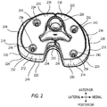
- FIG. 2 is a perspective drawing of an example tibial augment 200 and an example tibial platform 220.
- the elements shown are for a right knee, viewed upside-down and from behind, as if looking upward from the point of view of the tibia.
- the distal side of the tibial augment 200 is more clearly shown in FIG. 2 , along with the taper of the periphery of the tibial augment 200.
- the tibial augment 200 includes a lateral side 204.
- the lateral side 204 includes a lateral taper 216 on at least a portion of its periphery.
- the lateral side 204 includes a lateral posterior portion 212.
- the lateral posterior portion 212 includes a lateral portion taper 248 on at least a portion of its periphery.
- the tibial augment 200 also includes a medial side 206, which, in this example, is separate from the lateral side 204.
- the lateral 204 and medial 206 sides are located on opposite sides of the hole 226 that can couple to a stem (not shown).
- the medial side 206 includes a medial taper 218 on at least a portion of its periphery.
- the medial side 206 includes a medial posterior portion 214.
- the medial posterior portion 214 includes a medial portion taper 250 on at least a portion of its periphery.
- the tibial platform 220 has a periphery that is typically perpendicular to its proximal and distal sides, so that a footprint 228 of the proximal side of tibial platform 220 is the same size and shape as a footprint 230 of the distal side of tibial platform 220.
- the footprint of the proximal side of the tibial augment 200 is typically selected to match the footprint 230 of the distal side of tibial platform 220.
- the tibial augment 200 includes a lateral distal face 236, having a lateral distal footprint 232, and a medial distal face 238, having a medial distal footprint 234.
- the lateral distal footprint 232 and the medial distal footprint 234 are selected to coincide with or be slightly smaller than a footprint of the bone of the tibia.
- the tibial augment 200 may include a plurality of augment holes 240, 242, 244, 246 extending longitudinally through the tibial augment 200. In the example of FIG. 2 , four holes are shown, although other suitable numbers of augment holes can include two, three, five, six, or more than six.
- the augment holes 240, 242, 244, 246 coincide with and are parallel to a respective plurality of platform holes 252, 254, 256, 258.
- the platform holes 252, 254, 256, 258 extend into a distal side of the tibial platform 220. In some examples, the platform holes 252, 254, 256, 258 do not extend fully though the tibial platform 220.
- the platform holes 252, 254, 256, 258 are threaded, and the augment holes 240, 242, 244, 246 are unthreaded, so that the platform and augment holes may be used to securely screw the tibial augment 200 to the tibial platform 220.
- the tibial augments are sold as systems.
- FIGS. 3-14 show an example configuration of a system that can span a range of bone sizes and resection values.
- the tibial augments are available for two discrete values of resection, and three discrete augment sizes that can each accommodate a respective range of bone sizes.
- a system may include more or fewer numbers of parts. Using more parts in the system may be able to better fit a part to a particular set of patient conditions, but at the expense of maintaining inventory of more parts in the system, and possibly higher costs due to the increased number of part variations in the system.
- FIGS. 3-14 includes an end-on view of the distal side of a tibial augment.
- Each tibial augment has a lateral side, on the left-hand side of the figure, and has a medial side, on the right-hand side of the figure.
- the lateral sides are denoted by element numbers ending in 04
- the medial sides are denoted by element numbers ending in 06.
- FIGS. 3-14 An outline of a particular tibial bone footprint is superimposed onto each tibial augment.
- the bone footprints in FIGS. 3-14 are denoted by element numbers ending in 02.
- a practitioner can measure the size and/or shape of a particular bone of a patient, compare the measured bone size and/or shape to several specified sizes, and select one of the specified sizes as best representing the size and/or shape of the bone.
- An established convention for tibial measurements uses six specified bone sizes, denoted as C, D, E, F, G, and H, although other conventions may be used.
- Each footprint shown in FIGS. 3-14 is intended to represent an average bone size and shape for a particular specified bone size. For example, an average D-bone may have the footprint shown in FIGS.
- an actual bone classified as D-bone may be a little larger or a little smaller than the average, or may be shaped slightly differently than the average.
- the six specified bone sizes of C, D, E, F, G, and H are addressed by three discrete augment sizes, denoted as C/D, E/F, and G/H. More or fewer discrete augment sizes may also be used.
- the footprint of the distal side of the tapered augment fits entirely within the footprint of the tibia bone.
- there is no overhang of the tibial augment for an average bone size.
- the other five of the twelve examples show small regions around the periphery where there is a small overhang, mostly at the lateral posterior portion of the augment, and at the larger of the two resection values.
- having a taper around the periphery reduces the footprint of the tibial augment, especially compared with a comparable tibial augment that has no taper.
- having a taper that can vary on at least a portion of the tibial augment can further reduce the footprint of the tibial augment, especially in the lateral posterior portion of the tibial augment.
- the taper in the lateral posterior portion of the tibial augment may be larger than in other portions of the tibial augment.
Landscapes
- Health & Medical Sciences (AREA)
- Orthopedic Medicine & Surgery (AREA)
- Vascular Medicine (AREA)
- Life Sciences & Earth Sciences (AREA)
- Transplantation (AREA)
- Engineering & Computer Science (AREA)
- Biomedical Technology (AREA)
- Heart & Thoracic Surgery (AREA)
- Cardiology (AREA)
- Oral & Maxillofacial Surgery (AREA)
- Animal Behavior & Ethology (AREA)
- General Health & Medical Sciences (AREA)
- Public Health (AREA)
- Veterinary Medicine (AREA)
- Physical Education & Sports Medicine (AREA)
- Prostheses (AREA)
- Surgical Instruments (AREA)
Claims (11)
- Dispositif permettant d'augmenter une tige tibiale d'un genou humain, la tige tibiale étant couplée à un côté distal d'une plate-forme tibiale (120), un côté proximal de la plate-forme tibiale pouvant être couplé à une surface à des fins d'articulation avec un composant fémoral, la plate-forme tibiale comportant un côté interne (124) et un côté latéral (122), le dispositif comprenant :une augmentation tibiale (100) conçue pour être couplée à la plate-forme tibiale (120) à proximité d'un côté distal de la plate-forme tibiale, l'augmentation tibiale comprenant un côté interne (106) permettant une fixation au côté interne de la plate-forme tibiale, le côté interne de l'augmentation tibiale ayant une conicité interne (118) sur au moins une partie de sa périphérie s'étendant vers l'intérieur dans un sens distal, et un côté latéral (104) permettant une fixation au côté latéral de la plate-forme tibiale, le côté latéral de l'augmentation tibiale ayant une conicité latérale (116) sur au moins une partie de sa périphérie s'étendant vers l'intérieur dans un sens distal ;dans lequel au moins une partie de la conicité interne est différente d'au moins une partie de la conicité latérale ; etdans lequel la conicité interne (118) est constante sur la périphérie du côté interne (106) de l'augmentation tibiale ; etdans lequel la conicité latérale (116) est constante sur la périphérie du côté latéral (104) de l'augmentation tibiale.
- Dispositif selon la revendication 1, dans lequel la conicité interne (118) est comprise entre treize degrés et dix-huit degrés, inclus.
- Dispositif selon l'une quelconque des revendications 1 et 2, dans lequel la conicité latérale (116) est comprise entre dix degrés et dix-huit degrés, inclus.
- Dispositif selon l'une quelconque des revendications 1 à 3, dans lequel l'augmentation tibiale (100) est un implant d'augmentation tibiale conçu pour être fixé à demeure à la plate-forme tibiale (120).
- Dispositif selon l'une quelconque des revendications 1 à 4, dans lequel le côté interne (106) et le côté latéral (104) de l'augmentation tibiale (100) peuvent être disposés sur des côtés opposés de la tige tibiale.
- Dispositif selon l'une quelconque des revendications 1 à 5, dans lequel l'augmentation tibiale (200) comprend une pluralité de trous d'augmentation (240, 242, 244, 246) s'étendant à travers cette dernière, la pluralité de trous d'augmentation étant conçue pour s'aligner avec une pluralité de trous de la plate-forme tibiale.
- Dispositif selon l'une quelconque des revendications 1 à 6, dans lequel le côté interne (106) et le côté latéral (104) de l'augmentation tibiale sont des éléments discrets.
- Dispositif selon l'une quelconque des revendications 1 à 7, dans lequel l'augmentation tibiale (100, 200) comprend une périphérie dimensionnée et formée de façon à correspondre à une taille et une forme de périphérie de la plate-forme tibiale (120).
- Dispositif selon l'une quelconque des revendications 1 à 8, dans lequel l'augmentation tibiale (100, 200) comprend des surfaces proximale et distale planes.
- Dispositif selon l'une quelconque des revendications 1 à 9, dans lequel la conicité interne (118) et la conicité latérale (116) sont conçues pour correspondre à un profil osseux existant.
- Dispositif selon l'une quelconque des revendications 1 à 10, dans lequel l'augmentation tibiale (100, 200) fait partie d'un système qui comprend une pluralité d'augmentations de tailles différentes.
Applications Claiming Priority (3)
| Application Number | Priority Date | Filing Date | Title |
|---|---|---|---|
| US201361762040P | 2013-02-07 | 2013-02-07 | |
| US201361789245P | 2013-03-15 | 2013-03-15 | |
| PCT/US2014/014834 WO2014123979A1 (fr) | 2013-02-07 | 2014-02-05 | Augmentation tibiale conique |
Publications (2)
| Publication Number | Publication Date |
|---|---|
| EP2953583A1 EP2953583A1 (fr) | 2015-12-16 |
| EP2953583B1 true EP2953583B1 (fr) | 2017-08-23 |
Family
ID=50159544
Family Applications (1)
| Application Number | Title | Priority Date | Filing Date |
|---|---|---|---|
| EP14706397.8A Active EP2953583B1 (fr) | 2013-02-07 | 2014-02-05 | Augmentation tibiale conique |
Country Status (7)
| Country | Link |
|---|---|
| US (1) | US20140222155A1 (fr) |
| EP (1) | EP2953583B1 (fr) |
| JP (1) | JP6306612B2 (fr) |
| CN (1) | CN104968301B (fr) |
| AU (1) | AU2014215037B2 (fr) |
| ES (1) | ES2640380T3 (fr) |
| WO (1) | WO2014123979A1 (fr) |
Families Citing this family (5)
| Publication number | Priority date | Publication date | Assignee | Title |
|---|---|---|---|---|
| AU2014348630B2 (en) | 2013-11-13 | 2019-08-01 | Zimmer, Inc. | Fastener system |
| CN104814815B (zh) * | 2015-05-22 | 2016-10-05 | 北京爱康宜诚医疗器材股份有限公司 | 骨关节假体 |
| KR101872791B1 (ko) * | 2017-11-30 | 2018-06-29 | 주식회사 코렌텍 | 해부학적 형상을 가진 슬관절 보강요소 |
| EP3838226B1 (fr) * | 2019-12-17 | 2022-08-17 | implantcast GmbH | Composant prothétique |
| DE102022124193A1 (de) * | 2022-09-21 | 2024-03-21 | Aesculap Ag | Kniegelenkimplantataugment und Kniegelenkimplantat |
Family Cites Families (9)
| Publication number | Priority date | Publication date | Assignee | Title |
|---|---|---|---|---|
| US4769040A (en) * | 1986-11-18 | 1988-09-06 | Queen's University At Kingston | Tibial prosthesis |
| US5152797A (en) * | 1991-10-25 | 1992-10-06 | Johnson & Johnson Orthopaedics, Inc. | Modular prosthesis |
| US5344461A (en) * | 1993-02-12 | 1994-09-06 | Zimmer, Inc. | Modular implant provisional |
| US5387241A (en) * | 1994-01-28 | 1995-02-07 | Zimmer, Inc. | Ribbed augment for a prosthetic implant |
| ES2695400T3 (es) * | 2010-01-29 | 2019-01-04 | Smith & Nephew Inc | Prótesis de rodilla de retención de cruzado |
| CN201668542U (zh) * | 2010-05-12 | 2010-12-15 | 中国人民解放军第四军医大学 | 钽涂层人工膝关节假体 |
| AU2012217694B2 (en) * | 2011-02-15 | 2016-01-14 | Omnilife Science, Inc. | Modular prosthesis |
| CH704563B1 (de) * | 2011-02-21 | 2015-04-30 | Microport Orthopedics Inc | Patientenspezifischer Proberepositionsblock. |
| US8900317B2 (en) * | 2011-05-20 | 2014-12-02 | Zimmer, Inc. | Stabilizing prosthesis support structure |
-
2014
- 2014-02-05 EP EP14706397.8A patent/EP2953583B1/fr active Active
- 2014-02-05 JP JP2015557017A patent/JP6306612B2/ja active Active
- 2014-02-05 US US14/173,280 patent/US20140222155A1/en not_active Abandoned
- 2014-02-05 ES ES14706397.8T patent/ES2640380T3/es active Active
- 2014-02-05 CN CN201480007661.5A patent/CN104968301B/zh active Active
- 2014-02-05 WO PCT/US2014/014834 patent/WO2014123979A1/fr active Application Filing
- 2014-02-05 AU AU2014215037A patent/AU2014215037B2/en active Active
Non-Patent Citations (1)
| Title |
|---|
| None * |
Also Published As
| Publication number | Publication date |
|---|---|
| CN104968301B (zh) | 2017-03-22 |
| US20140222155A1 (en) | 2014-08-07 |
| WO2014123979A1 (fr) | 2014-08-14 |
| AU2014215037B2 (en) | 2017-11-16 |
| EP2953583A1 (fr) | 2015-12-16 |
| AU2014215037A1 (en) | 2015-09-17 |
| JP6306612B2 (ja) | 2018-04-04 |
| ES2640380T3 (es) | 2017-11-02 |
| JP2016506817A (ja) | 2016-03-07 |
| CN104968301A (zh) | 2015-10-07 |
Similar Documents
| Publication | Publication Date | Title |
|---|---|---|
| EP3352708B1 (fr) | Système de prothèse comprenant un élément porteur tibial | |
| US8480752B2 (en) | Tibial bearing having increased axial-rotation | |
| EP2143403B1 (fr) | Prothèse de genou | |
| US8192498B2 (en) | Posterior cructiate-retaining orthopaedic knee prosthesis having controlled condylar curvature | |
| US8187335B2 (en) | Posterior stabilized orthopaedic knee prosthesis having controlled condylar curvature | |
| EP2953583B1 (fr) | Augmentation tibiale conique | |
| US9855147B2 (en) | Modular prosthesis | |
| US9883948B2 (en) | Adjustable height arthroplasty plate | |
| AU2012275459B2 (en) | Posterior stabilized orthopaedic prosthesis assembly | |
| CA2430809A1 (fr) | Prothese de genou | |
| EP3302370B1 (fr) | Système d'essai de palier | |
| US9119723B2 (en) | Posterior stabilized orthopaedic prosthesis assembly | |
| US9867628B2 (en) | Device for extraction of prosthetic implants | |
| US20140277536A1 (en) | Orthopaedic knee prosthesis having stem components with a varying number of slots | |
| CN109077833A (zh) | 股骨髁假体组件 | |
| US20160367369A1 (en) | Cartilage prosthetic implant | |
| US20210251765A1 (en) | Radial Head Orthopedic Implant Apparatus and Method of Using Same | |
| RU2592606C1 (ru) | Имплантат позвонка | |
| BG1793U1 (bg) | Стебло на тазобедрена става |
Legal Events
| Date | Code | Title | Description |
|---|---|---|---|
| PUAI | Public reference made under article 153(3) epc to a published international application that has entered the european phase |
Free format text: ORIGINAL CODE: 0009012 |
|
| 17P | Request for examination filed |
Effective date: 20150903 |
|
| AK | Designated contracting states |
Kind code of ref document: A1 Designated state(s): AL AT BE BG CH CY CZ DE DK EE ES FI FR GB GR HR HU IE IS IT LI LT LU LV MC MK MT NL NO PL PT RO RS SE SI SK SM TR |
|
| AX | Request for extension of the european patent |
Extension state: BA ME |
|
| DAX | Request for extension of the european patent (deleted) | ||
| 17Q | First examination report despatched |
Effective date: 20160907 |
|
| RIC1 | Information provided on ipc code assigned before grant |
Ipc: A61F 2/38 20060101ALI20170124BHEP Ipc: A61F 2/30 20060101AFI20170124BHEP |
|
| GRAP | Despatch of communication of intention to grant a patent |
Free format text: ORIGINAL CODE: EPIDOSNIGR1 |
|
| INTG | Intention to grant announced |
Effective date: 20170307 |
|
| GRAS | Grant fee paid |
Free format text: ORIGINAL CODE: EPIDOSNIGR3 |
|
| GRAA | (expected) grant |
Free format text: ORIGINAL CODE: 0009210 |
|
| AK | Designated contracting states |
Kind code of ref document: B1 Designated state(s): AL AT BE BG CH CY CZ DE DK EE ES FI FR GB GR HR HU IE IS IT LI LT LU LV MC MK MT NL NO PL PT RO RS SE SI SK SM TR |
|
| REG | Reference to a national code |
Ref country code: GB Ref legal event code: FG4D |
|
| REG | Reference to a national code |
Ref country code: CH Ref legal event code: EP Ref country code: CH Ref legal event code: NV Representative=s name: MICHELI AND CIE SA, CH |
|
| REG | Reference to a national code |
Ref country code: AT Ref legal event code: REF Ref document number: 920492 Country of ref document: AT Kind code of ref document: T Effective date: 20170915 |
|
| REG | Reference to a national code |
Ref country code: IE Ref legal event code: FG4D |
|
| REG | Reference to a national code |
Ref country code: DE Ref legal event code: R096 Ref document number: 602014013469 Country of ref document: DE |
|
| REG | Reference to a national code |
Ref country code: ES Ref legal event code: FG2A Ref document number: 2640380 Country of ref document: ES Kind code of ref document: T3 Effective date: 20171102 |
|
| REG | Reference to a national code |
Ref country code: DE Ref legal event code: R082 Ref document number: 602014013469 Country of ref document: DE Representative=s name: VENNER SHIPLEY LLP, DE Ref country code: DE Ref legal event code: R082 Ref document number: 602014013469 Country of ref document: DE Representative=s name: VENNER SHIPLEY LLP, CAMBRIDGE, GB |
|
| REG | Reference to a national code |
Ref country code: NL Ref legal event code: MP Effective date: 20170823 |
|
| REG | Reference to a national code |
Ref country code: LT Ref legal event code: MG4D |
|
| REG | Reference to a national code |
Ref country code: FR Ref legal event code: PLFP Year of fee payment: 5 |
|
| REG | Reference to a national code |
Ref country code: AT Ref legal event code: MK05 Ref document number: 920492 Country of ref document: AT Kind code of ref document: T Effective date: 20170823 |
|
| PG25 | Lapsed in a contracting state [announced via postgrant information from national office to epo] |
Ref country code: FI Free format text: LAPSE BECAUSE OF FAILURE TO SUBMIT A TRANSLATION OF THE DESCRIPTION OR TO PAY THE FEE WITHIN THE PRESCRIBED TIME-LIMIT Effective date: 20170823 Ref country code: AT Free format text: LAPSE BECAUSE OF FAILURE TO SUBMIT A TRANSLATION OF THE DESCRIPTION OR TO PAY THE FEE WITHIN THE PRESCRIBED TIME-LIMIT Effective date: 20170823 Ref country code: NL Free format text: LAPSE BECAUSE OF FAILURE TO SUBMIT A TRANSLATION OF THE DESCRIPTION OR TO PAY THE FEE WITHIN THE PRESCRIBED TIME-LIMIT Effective date: 20170823 Ref country code: NO Free format text: LAPSE BECAUSE OF FAILURE TO SUBMIT A TRANSLATION OF THE DESCRIPTION OR TO PAY THE FEE WITHIN THE PRESCRIBED TIME-LIMIT Effective date: 20171123 Ref country code: HR Free format text: LAPSE BECAUSE OF FAILURE TO SUBMIT A TRANSLATION OF THE DESCRIPTION OR TO PAY THE FEE WITHIN THE PRESCRIBED TIME-LIMIT Effective date: 20170823 Ref country code: SE Free format text: LAPSE BECAUSE OF FAILURE TO SUBMIT A TRANSLATION OF THE DESCRIPTION OR TO PAY THE FEE WITHIN THE PRESCRIBED TIME-LIMIT Effective date: 20170823 Ref country code: LT Free format text: LAPSE BECAUSE OF FAILURE TO SUBMIT A TRANSLATION OF THE DESCRIPTION OR TO PAY THE FEE WITHIN THE PRESCRIBED TIME-LIMIT Effective date: 20170823 |
|
| PG25 | Lapsed in a contracting state [announced via postgrant information from national office to epo] |
Ref country code: LV Free format text: LAPSE BECAUSE OF FAILURE TO SUBMIT A TRANSLATION OF THE DESCRIPTION OR TO PAY THE FEE WITHIN THE PRESCRIBED TIME-LIMIT Effective date: 20170823 Ref country code: RS Free format text: LAPSE BECAUSE OF FAILURE TO SUBMIT A TRANSLATION OF THE DESCRIPTION OR TO PAY THE FEE WITHIN THE PRESCRIBED TIME-LIMIT Effective date: 20170823 Ref country code: BG Free format text: LAPSE BECAUSE OF FAILURE TO SUBMIT A TRANSLATION OF THE DESCRIPTION OR TO PAY THE FEE WITHIN THE PRESCRIBED TIME-LIMIT Effective date: 20171123 Ref country code: GR Free format text: LAPSE BECAUSE OF FAILURE TO SUBMIT A TRANSLATION OF THE DESCRIPTION OR TO PAY THE FEE WITHIN THE PRESCRIBED TIME-LIMIT Effective date: 20171124 Ref country code: IS Free format text: LAPSE BECAUSE OF FAILURE TO SUBMIT A TRANSLATION OF THE DESCRIPTION OR TO PAY THE FEE WITHIN THE PRESCRIBED TIME-LIMIT Effective date: 20171223 Ref country code: PL Free format text: LAPSE BECAUSE OF FAILURE TO SUBMIT A TRANSLATION OF THE DESCRIPTION OR TO PAY THE FEE WITHIN THE PRESCRIBED TIME-LIMIT Effective date: 20170823 |
|
| PG25 | Lapsed in a contracting state [announced via postgrant information from national office to epo] |
Ref country code: RO Free format text: LAPSE BECAUSE OF FAILURE TO SUBMIT A TRANSLATION OF THE DESCRIPTION OR TO PAY THE FEE WITHIN THE PRESCRIBED TIME-LIMIT Effective date: 20170823 Ref country code: DK Free format text: LAPSE BECAUSE OF FAILURE TO SUBMIT A TRANSLATION OF THE DESCRIPTION OR TO PAY THE FEE WITHIN THE PRESCRIBED TIME-LIMIT Effective date: 20170823 Ref country code: CZ Free format text: LAPSE BECAUSE OF FAILURE TO SUBMIT A TRANSLATION OF THE DESCRIPTION OR TO PAY THE FEE WITHIN THE PRESCRIBED TIME-LIMIT Effective date: 20170823 |
|
| REG | Reference to a national code |
Ref country code: DE Ref legal event code: R097 Ref document number: 602014013469 Country of ref document: DE |
|
| PG25 | Lapsed in a contracting state [announced via postgrant information from national office to epo] |
Ref country code: SK Free format text: LAPSE BECAUSE OF FAILURE TO SUBMIT A TRANSLATION OF THE DESCRIPTION OR TO PAY THE FEE WITHIN THE PRESCRIBED TIME-LIMIT Effective date: 20170823 Ref country code: SM Free format text: LAPSE BECAUSE OF FAILURE TO SUBMIT A TRANSLATION OF THE DESCRIPTION OR TO PAY THE FEE WITHIN THE PRESCRIBED TIME-LIMIT Effective date: 20170823 Ref country code: EE Free format text: LAPSE BECAUSE OF FAILURE TO SUBMIT A TRANSLATION OF THE DESCRIPTION OR TO PAY THE FEE WITHIN THE PRESCRIBED TIME-LIMIT Effective date: 20170823 |
|
| PLBE | No opposition filed within time limit |
Free format text: ORIGINAL CODE: 0009261 |
|
| STAA | Information on the status of an ep patent application or granted ep patent |
Free format text: STATUS: NO OPPOSITION FILED WITHIN TIME LIMIT |
|
| 26N | No opposition filed |
Effective date: 20180524 |
|
| PG25 | Lapsed in a contracting state [announced via postgrant information from national office to epo] |
Ref country code: SI Free format text: LAPSE BECAUSE OF FAILURE TO SUBMIT A TRANSLATION OF THE DESCRIPTION OR TO PAY THE FEE WITHIN THE PRESCRIBED TIME-LIMIT Effective date: 20170823 |
|
| PG25 | Lapsed in a contracting state [announced via postgrant information from national office to epo] |
Ref country code: MC Free format text: LAPSE BECAUSE OF FAILURE TO SUBMIT A TRANSLATION OF THE DESCRIPTION OR TO PAY THE FEE WITHIN THE PRESCRIBED TIME-LIMIT Effective date: 20170823 |
|
| REG | Reference to a national code |
Ref country code: BE Ref legal event code: MM Effective date: 20180228 |
|
| PG25 | Lapsed in a contracting state [announced via postgrant information from national office to epo] |
Ref country code: LU Free format text: LAPSE BECAUSE OF NON-PAYMENT OF DUE FEES Effective date: 20180205 |
|
| PG25 | Lapsed in a contracting state [announced via postgrant information from national office to epo] |
Ref country code: BE Free format text: LAPSE BECAUSE OF NON-PAYMENT OF DUE FEES Effective date: 20180228 |
|
| PG25 | Lapsed in a contracting state [announced via postgrant information from national office to epo] |
Ref country code: MT Free format text: LAPSE BECAUSE OF NON-PAYMENT OF DUE FEES Effective date: 20180205 |
|
| PG25 | Lapsed in a contracting state [announced via postgrant information from national office to epo] |
Ref country code: PT Free format text: LAPSE BECAUSE OF FAILURE TO SUBMIT A TRANSLATION OF THE DESCRIPTION OR TO PAY THE FEE WITHIN THE PRESCRIBED TIME-LIMIT Effective date: 20170823 |
|
| PG25 | Lapsed in a contracting state [announced via postgrant information from national office to epo] |
Ref country code: CY Free format text: LAPSE BECAUSE OF FAILURE TO SUBMIT A TRANSLATION OF THE DESCRIPTION OR TO PAY THE FEE WITHIN THE PRESCRIBED TIME-LIMIT Effective date: 20170823 Ref country code: HU Free format text: LAPSE BECAUSE OF FAILURE TO SUBMIT A TRANSLATION OF THE DESCRIPTION OR TO PAY THE FEE WITHIN THE PRESCRIBED TIME-LIMIT; INVALID AB INITIO Effective date: 20140205 Ref country code: MK Free format text: LAPSE BECAUSE OF NON-PAYMENT OF DUE FEES Effective date: 20170823 |
|
| PG25 | Lapsed in a contracting state [announced via postgrant information from national office to epo] |
Ref country code: AL Free format text: LAPSE BECAUSE OF FAILURE TO SUBMIT A TRANSLATION OF THE DESCRIPTION OR TO PAY THE FEE WITHIN THE PRESCRIBED TIME-LIMIT Effective date: 20170823 |
|
| REG | Reference to a national code |
Ref country code: DE Ref legal event code: R082 Ref document number: 602014013469 Country of ref document: DE Representative=s name: VENNER SHIPLEY GERMANY LLP, DE Ref country code: DE Ref legal event code: R082 Ref document number: 602014013469 Country of ref document: DE Representative=s name: VENNER SHIPLEY LLP, DE |
|
| PGFP | Annual fee paid to national office [announced via postgrant information from national office to epo] |
Ref country code: FR Payment date: 20230109 Year of fee payment: 10 |
|
| PGFP | Annual fee paid to national office [announced via postgrant information from national office to epo] |
Ref country code: TR Payment date: 20230203 Year of fee payment: 10 Ref country code: IT Payment date: 20221220 Year of fee payment: 10 |
|
| P01 | Opt-out of the competence of the unified patent court (upc) registered |
Effective date: 20230525 |
|
| PGFP | Annual fee paid to national office [announced via postgrant information from national office to epo] |
Ref country code: ES Payment date: 20240305 Year of fee payment: 11 Ref country code: IE Payment date: 20240122 Year of fee payment: 11 |
|
| PGFP | Annual fee paid to national office [announced via postgrant information from national office to epo] |
Ref country code: DE Payment date: 20240109 Year of fee payment: 11 Ref country code: CH Payment date: 20240301 Year of fee payment: 11 Ref country code: GB Payment date: 20240108 Year of fee payment: 11 |