EP2953564B2 - Ensemble d'implantation comprenant un instrument d'entraînement pre-monté sur un implant osseux - Google Patents
Ensemble d'implantation comprenant un instrument d'entraînement pre-monté sur un implant osseux Download PDFInfo
- Publication number
- EP2953564B2 EP2953564B2 EP14706889.4A EP14706889A EP2953564B2 EP 2953564 B2 EP2953564 B2 EP 2953564B2 EP 14706889 A EP14706889 A EP 14706889A EP 2953564 B2 EP2953564 B2 EP 2953564B2
- Authority
- EP
- European Patent Office
- Prior art keywords
- anchoring element
- bone anchoring
- bone
- instrument
- drive shaft
- Prior art date
- Legal status (The legal status is an assumption and is not a legal conclusion. Google has not performed a legal analysis and makes no representation as to the accuracy of the status listed.)
- Active
Links
Images


Classifications
-
- A—HUMAN NECESSITIES
- A61—MEDICAL OR VETERINARY SCIENCE; HYGIENE
- A61B—DIAGNOSIS; SURGERY; IDENTIFICATION
- A61B17/00—Surgical instruments, devices or methods
- A61B17/56—Surgical instruments or methods for treatment of bones or joints; Devices specially adapted therefor
- A61B17/58—Surgical instruments or methods for treatment of bones or joints; Devices specially adapted therefor for osteosynthesis, e.g. bone plates, screws or setting implements
- A61B17/68—Internal fixation devices, including fasteners and spinal fixators, even if a part thereof projects from the skin
- A61B17/70—Spinal positioners or stabilisers, e.g. stabilisers comprising fluid filler in an implant
- A61B17/7097—Stabilisers comprising fluid filler in an implant, e.g. balloon; devices for inserting or filling such implants
- A61B17/7098—Stabilisers comprising fluid filler in an implant, e.g. balloon; devices for inserting or filling such implants wherein the implant is permeable or has openings, e.g. fenestrated screw
-
- A—HUMAN NECESSITIES
- A61—MEDICAL OR VETERINARY SCIENCE; HYGIENE
- A61B—DIAGNOSIS; SURGERY; IDENTIFICATION
- A61B17/00—Surgical instruments, devices or methods
- A61B17/56—Surgical instruments or methods for treatment of bones or joints; Devices specially adapted therefor
- A61B17/58—Surgical instruments or methods for treatment of bones or joints; Devices specially adapted therefor for osteosynthesis, e.g. bone plates, screws or setting implements
- A61B17/68—Internal fixation devices, including fasteners and spinal fixators, even if a part thereof projects from the skin
- A61B17/685—Elements to be fitted on the end of screws or wires, e.g. protective caps
-
- A—HUMAN NECESSITIES
- A61—MEDICAL OR VETERINARY SCIENCE; HYGIENE
- A61B—DIAGNOSIS; SURGERY; IDENTIFICATION
- A61B17/00—Surgical instruments, devices or methods
- A61B17/56—Surgical instruments or methods for treatment of bones or joints; Devices specially adapted therefor
- A61B17/58—Surgical instruments or methods for treatment of bones or joints; Devices specially adapted therefor for osteosynthesis, e.g. bone plates, screws or setting implements
- A61B17/68—Internal fixation devices, including fasteners and spinal fixators, even if a part thereof projects from the skin
- A61B17/70—Spinal positioners or stabilisers, e.g. stabilisers comprising fluid filler in an implant
- A61B17/7074—Tools specially adapted for spinal fixation operations other than for bone removal or filler handling
- A61B17/7076—Tools specially adapted for spinal fixation operations other than for bone removal or filler handling for driving, positioning or assembling spinal clamps or bone anchors specially adapted for spinal fixation
- A61B17/7082—Tools specially adapted for spinal fixation operations other than for bone removal or filler handling for driving, positioning or assembling spinal clamps or bone anchors specially adapted for spinal fixation for driving, i.e. rotating, screws or screw parts specially adapted for spinal fixation, e.g. for driving polyaxial or tulip-headed screws
-
- A—HUMAN NECESSITIES
- A61—MEDICAL OR VETERINARY SCIENCE; HYGIENE
- A61B—DIAGNOSIS; SURGERY; IDENTIFICATION
- A61B17/00—Surgical instruments, devices or methods
- A61B17/56—Surgical instruments or methods for treatment of bones or joints; Devices specially adapted therefor
- A61B17/58—Surgical instruments or methods for treatment of bones or joints; Devices specially adapted therefor for osteosynthesis, e.g. bone plates, screws or setting implements
- A61B17/68—Internal fixation devices, including fasteners and spinal fixators, even if a part thereof projects from the skin
- A61B17/84—Fasteners therefor or fasteners being internal fixation devices
- A61B17/86—Pins or screws or threaded wires; nuts therefor
- A61B17/864—Pins or screws or threaded wires; nuts therefor hollow, e.g. with socket or cannulated
-
- A—HUMAN NECESSITIES
- A61—MEDICAL OR VETERINARY SCIENCE; HYGIENE
- A61B—DIAGNOSIS; SURGERY; IDENTIFICATION
- A61B17/00—Surgical instruments, devices or methods
- A61B17/56—Surgical instruments or methods for treatment of bones or joints; Devices specially adapted therefor
- A61B17/58—Surgical instruments or methods for treatment of bones or joints; Devices specially adapted therefor for osteosynthesis, e.g. bone plates, screws or setting implements
- A61B17/88—Osteosynthesis instruments; Methods or means for implanting or extracting internal or external fixation devices
- A61B17/8875—Screwdrivers, spanners or wrenches
- A61B17/8886—Screwdrivers, spanners or wrenches holding the screw head
- A61B17/8888—Screwdrivers, spanners or wrenches holding the screw head at its central region
-
- A—HUMAN NECESSITIES
- A61—MEDICAL OR VETERINARY SCIENCE; HYGIENE
- A61B—DIAGNOSIS; SURGERY; IDENTIFICATION
- A61B17/00—Surgical instruments, devices or methods
- A61B17/34—Trocars; Puncturing needles
- A61B17/3468—Trocars; Puncturing needles for implanting or removing devices, e.g. prostheses, implants, seeds, wires
-
- A—HUMAN NECESSITIES
- A61—MEDICAL OR VETERINARY SCIENCE; HYGIENE
- A61B—DIAGNOSIS; SURGERY; IDENTIFICATION
- A61B17/00—Surgical instruments, devices or methods
- A61B17/34—Trocars; Puncturing needles
- A61B17/3417—Details of tips or shafts, e.g. grooves, expandable, bendable; Multiple coaxial sliding cannulas, e.g. for dilating
- A61B17/3421—Cannulas
- A61B2017/3445—Cannulas used as instrument channel for multiple instruments
Definitions
- the invention relates to the field of osteosynthesis, in particular spinal osteosynthesis, and more particularly that of the placement of bone implants.
- the invention relates more particularly to an implantation assembly comprising a bone anchoring element and an instrument for driving the bone anchoring element, the instrument being intended to drive the bone anchoring element by screwing into a hole previously drilled or not in a bony structure.
- bone anchoring elements for spinal osteosynthesis comprise, in known manner, a threaded rod provided, at one of its ends, with a head capable of receiving directly or via a connector a connecting element.
- the bone anchoring elements are intended to be fixed on the vertebrae concerned for stabilization and/or osteosynthesis.
- the threaded rod of the bone anchoring element is positioned in a hole drilled, previously or not, in a vertebra.
- the insertion of the bone anchoring element into the vertebra is continued using a driving instrument, of the screwdriver type, placed on the head of the element of bone anchorage.
- the insertion of the bone anchoring element is carried out until reaching a sufficient insertion to ensure the fixing of the bone anchoring element in the vertebra.
- An implantation assembly according to the preamble of claim 1 is known from US patent application US 2012/0197311 .
- a bone anchoring element, provided with a drive shaft and arranged in a packaging, is known from the French patent application 2,954,689 .
- One of the drawbacks encountered with the training instruments conventionally implemented is the wear of their coupling end with the head of the bone anchoring element. If this wear is linked to the repeated use of training instruments (pairing combined with the tightening torque exerted by the extremity on the bone anchoring element), it is also linked, or even accelerated, by recurring cycles of sterilization after each surgical intervention, during which the instruments undergo aggressive actions of solvents, decontaminants, etc. When the training instruments are worn, the result is a loss of rigidity of the training instrument/bone anchoring element assembly, thus increasing the risks of incorrect placement of the training element. bone anchorage in the vertebral body.
- the invention aims to remedy these problems by proposing an implantation assembly eliminating any problem of wear of the training instruments and any problem of pairing between such an instrument and a bone anchoring element during an intervention. surgical.
- Another object of the invention is to provide a functional implantation assembly making it possible to ensure, at each surgical intervention, surgical instruments free of any wear and whose sterility is guaranteed.
- Another object of the invention is to provide an implantation assembly allowing optimum tolerance so as to ensure the maintenance of the training instrument on the bone anchoring element, in particular when they are subjected to stresses. bending.
- the invention relates to an implantation assembly as stated in claim 1.
- pre-assembled is meant a drive instrument whose drive shaft is integrally coupled to the bone anchoring element, and this prior to the implantation of the bone anchorage.
- the pre-assembly of the training instrument on the bone anchoring element allows on the one hand a saving of surgical time due to the elimination of the operation of setting up the instrument. training on the bone anchoring element and on the other hand a reduction in the operative risk, the duration of anesthesia being correspondingly reduced.
- the implantation assembly comprises means for axial retention of the drive shaft on the bone anchoring element.
- the head is mounted on the threaded rod free in rotation with respect to the threaded rod.
- the head has a threaded longitudinal cavity opening into a transverse channel capable of receiving a connecting element, the drive shaft of said instrument having one end cooperating with the bottom of the transverse channel of the head of the element bone anchor.
- the implantation assembly comprises at least one extension tube of the bone anchoring element dimensioned to receive within it the drive axis, the extension tube having an end of coupling with the head of the bone anchoring element.
- the extension tube is provided so that, when it is coupled to the head of the bone anchoring element, it is arranged with the drive shaft so as to allow the rotational movement of the drive axis around its longitudinal axis.
- said implantation assembly comprises a tissue protection tube arranged to receive within it the bone anchoring element.
- the bone anchoring element on which at least the drive instrument is pre-mounted, is placed in a sealed packaging in sterile packaging.
- the sterile packaging packaging further comprises the extension tube and/or the protective tube.
- the implantation assembly is sterile.
- the implantation assembly is for single use.
- the driving instrument forms a guide for a surgical instrument having a tubular body. It thus makes it possible to fix again on the bone anchoring element a correction instrument of the tube type.
- the drive shaft is a screwdriver bar.
- the implantation instrument is disposable.
- the threaded rod comprises an axial bore having an end opening at the level of the head and at least one radial slot communicating with the axial bore
- the drive instrument comprises a drive shaft pre - mounted in a removable manner on the bone anchoring element, the drive shaft being traversed longitudinally by a passage channel communicating with the axial bore of the bone anchoring element.
- communicating means a passage channel arranged to provide access to the axial bore of the bone anchoring element. It can be a direct or indirect communication.
- pre-assembled means a drive instrument whose drive shaft is integrally coupled to the bone anchoring element, and this prior to the implantation of the bone anchoring element.
- the implantation assembly thus configured makes it possible to ensure the distribution of a fixing substance, such as cement, or of any other product, such as for example a bone treatment substance, in the bone structure in which the bone anchoring element is implanted, by eliminating any risk of leakage of the substance distributed outside the bone structure during its distribution.
- a fixing substance such as cement
- any other product such as for example a bone treatment substance
- this configuration allows the distribution of a substance during the driving of the bone anchoring element by the driving instrument. This has the advantage of not limiting the distribution of the substance in localized areas of the bone structure corresponding to the location of the radial lumen of the threaded rod but on the contrary of distributing it over a greater height.
- the substance dispensed is a fixation substance, an improvement in the fixation of the bone anchoring element in the bone structure ensues.
- the threaded rod may comprise a plurality of radial slots arranged in pairs, each pair of slots being arranged at the same distance from each other, the radial slots of each pair being arranged diametrically opposite.
- the threaded rod comprises a plurality of radial slots arranged at equal distance from each other in the axial direction and equidistant from each other by 120 degrees in the radial direction.
- extension tube Once the extension tube is in place, provision may be made to dismantle the driving instrument from the bone anchoring element.
- an implantation assembly 1 for osteosynthesis comprising a bone anchoring element 2 on which is removably pre-mounted a driving instrument 3 of the element bone anchor 2.
- the bone anchoring element 2 may also be designated by the term screw.
- the bone anchoring element 2 comprises a threaded rod 4 provided at one of its ends 40 with a head 5 in the shape of a tulip.
- the head 5 thus has a threaded longitudinal cavity 6 opening into a transverse channel 7.
- the transverse channel 7 is intended to receive a connecting element, for example a connecting rod, the threaded longitudinal cavity 6 being intended to receive a blocking cap of the connecting element on the head 5 of the bone anchoring element 2.
- the bone anchoring element 2 is a multiaxial screw. More particularly, the head 5 is mounted free in rotation on the threaded rod 4. To do this, the threaded rod 4 has an end 40 of spherical shape housed in the lower part of the head 5, in a space provided under the transverse channel 7 and leading into the latter. The space has an exit opening for the passage of the threaded rod 4 during assembly of the bone anchoring element in the head 5.
- a part forming a cradle 9 is provided at the bottom of the transverse channel 7 of the screw head 5, said part having an upper housing intended to receive the connecting element once the driving instrument 3 has been removed.
- the part forming a cradle 9 also has a lower face of a shape complementary to that on which it is intended to be placed. In the illustrated embodiment, the lower face has a shape complementary to that of the end 40 of the rod threaded.
- the part forming the cradle 9 further comprises a through hole to allow the passage of a portion of the training instrument 3.
- the drive instrument 3 comprises a drive shaft 8 having an end 80 arranged to cooperate with the bottom of the transverse channel 7 of the head 5 of the screw 2. This end 80 of "fitting or mating end 80".
- the head 5 and the threaded rod 4 of the bone anchoring element 2 are arranged relative to each other so that the threaded rod 4 opens into the transverse channel 7
- the drive shaft 8 is then pre-mounted directly on the end 40 of the threaded rod opening into the transverse channel 7.
- the end 40 of the threaded rod has a cavity 41 of complementary shape with the connection end 80 of the drive shaft 8.
- the gripping and handling part 8A is provided with a recess 8C for receiving a gripping handle (handle not shown).
- a gripping handle handle not shown.
- the presence of a handle has the advantage of facilitating the handling of the drive shaft 8.
- the implantation assembly 1 advantageously comprises an intermediate retaining part placed between the head 5 of the anchoring element bone 2 and the drive shaft 8 of the instrument.
- the intermediate holding piece is arranged with the head 5 and the drive shaft 8 to hold the latter in alignment with the threaded rod 4 of the bone anchoring element 2 on which the drive instrument 3 is pre-assembled.
- the intermediate retaining piece is made of a flexible material, such as an elastomer for example.
- the intermediate elastomer holding piece advantageously has a section slightly greater than the section of the longitudinal cavity 6 of the screw head 5.
- the intermediate piece formed of flexible material deforms. The intermediate piece thus released makes it possible to maintain the drive shaft 8 coupled to the bone anchoring element 2.
- the intermediate holding piece is sized to cover at least the portion of the connecting piece 8B extending into the longitudinal cavity 6 when the training instrument 3 is pre-mounted on the bone anchoring element 2.
- the intermediate retaining piece advantageously has a length equal to the depth P of the longitudinal cavity to which is added the length L of the portion of the drive shaft 8 extending between the opening of the longitudinal cavity 6 of the screw head 6 and the end 90 of the gripping part 8A.
- the intermediate holding piece is mounted on the drive shaft 8 in a removable manner.
- the drive shaft 8 constitutes a guide for surgical instruments having a tubular body.
- it can be implemented to guide a tube itself serving as a guide for the connecting element.
- an implantation assembly comprising an extension tube of the bone anchoring element, said tube being pre-mounted on the head 5 of the screw and traversed within it by the drive shaft 8.
- the extension tube has an internal section allowing the axial rotational movement of the drive shaft 8.
- Such a tube is shown not mounted on the figure 7 (reference 30).
- the pre-assembled bone anchoring element 2 of the training instrument 3 according to the invention is placed in a sterile packaging packaging 20 .
- a tube extension tube 30 of the bone anchoring element adapted to be mounted on the bone anchoring element 2.
- the extension tube 30 is arranged so that, when it is coupled to the head 5 of the bone anchoring element 2, it is traversed by the drive shaft 8 and is arranged with the latter so as to allow the rotational movement of said drive shaft 8 around its longitudinal axis (axis longitudinal of the drive axis 8).
- the implantation assembly and the extension tube 30 thus placed in a sterile packaging package 20 form a kit 100.
- the illustrated kit 100 comprises an implantation assembly 1 and an extension tube 30.
- kit is not limited to these two instruments and that it can comprise several sets of implantation like several mounting tubes or like any other type of single-use instruments necessary for a surgical intervention.
- provision may be made to produce a kit comprising an implantation assembly as described above on which the extension tube is also pre-mounted.
- the kit may include, like that described previously, any type of single-use instruments necessary for a surgical intervention.
- kits 110 comprising an implantation assembly 1 as described previously and a tissue protection or expansion tube 21 or a set of protection/dilation tubes nested one inside the other, and arranged in sterile packaging 20.
- the figure 8 illustrates an implantation assembly 1 and a tube or assembly of protection/dilation tubes 21 not pre-assembled.
- a kit can be provided in which the tissue protection/dilation tube(s) is (are) pre-mounted on the bone anchoring element, the drive shaft passing through the said tube(s).
- the figures 4 to 6 illustrate an implantation assembly 1 according to another embodiment.
- the means for retaining the drive shaft 8 on the bone anchoring element 2, formed in the embodiment previously described by the intermediate retaining part, are provided directly on the shaft training 8.
- the connecting piece 8B comprises two elastic tabs 12, 13 extending on either side of its body in a direction substantially longitudinal. Said lugs 12, 13 are arranged so as to become embedded in the longitudinal cavity 6 of the screw head 5 when the driving instrument 3 is pre-mounted on the bone anchoring element 2.
- the connecting piece 8B has, at the level of the shaft portion delimited by the lateral lugs 12, 13, an external section slightly greater than the internal section of the longitudinal cavity 6.
- the flexible tabs 12, 13 respectively comprise an external shoulder 14, 15, each shoulder being intended to come into abutment on the upper face 50 of the head 5 of screws.
- external shoulder is meant a shoulder extending in the direction opposite to the longitudinal cavity 6 when the training instrument 3 is pre-mounted on the bone anchoring element 2.
- upper is given with reference to the figures.
- the connecting piece 8B is represented as “full”. According to an advantageous embodiment, it can be provided that the connecting piece 8B has a longitudinal channel 83 like the connecting piece 8B represented on the picture 2 .
- the gripping and handling part 8A being itself tubular, this makes it possible, when the training instrument 3 is implemented with a suitable bone anchoring element (cannulated element with windows), to inject cement or other product. Such a configuration is illustrated in the figure 13 .
- the bone anchoring element 2 comprises an axial bore 42 extending from the end opposite the anchoring end 45 (spherical end 40 for the embodiment illustrated in the figure 13 ). It further comprises radial slots 44 communicating with the axial bore 42 (only six are shown).
- the axial bore 42 has an end opening at the end 40 of the threaded rod opening into the cavity 41.
- the axial bore does not have an opening at the end opposite end 40, in the axial direction.
- the bone anchoring element comprises eight radial slots (only six being shown). It is of course obvious that the number of radial slots can vary without departing from the scope of the invention.
- the radial slots 44 are arranged in pairs.
- the radial lumens of each pair are arranged diametrically opposite, while each pair is arranged at a set distance from each other.
- the pairs of lights are arranged at equal distance from each other.
- the slots are arranged at equal distance from each other in the axial direction and equidistant from each other by 120 degrees in the radial direction. It is of course obvious that the invention is not limited to these configurations, the number and location of the lights can vary without departing from the scope of the invention.
- the driving instrument is cannulated. More particularly, the drive shaft 8 is arranged to have a passage channel extending over the entire length of said shaft 8. The channel is arranged so as to communicate, directly or indirectly, in the axial bore of the bone anchoring element.
- Direct communication denotes a passage channel opening directly into the axial bore of the bone anchoring element;
- indirect communication is meant a passage channel communicating with the axial bore of the bone angel element via a cavity: the connection end 80 is not embedded to the bottom of the cavity 41 provided at the spherical end 40 of the bone anchoring element. Therefore, the passage channel opens into a portion of the cavity 41 which itself communicates with the axial bore 42.
- the injection of cement or other substance is carried out using a cannula 60 inserted into the passage channel of the drive shaft.
- the figure 13 shows a partial view of the cannula 60 mounted in the channel. It is of course obvious that this is a particular embodiment of injecting substances.
- the use of a cannula is not essential, cement and other substances can be injected directly into the passage channel.
- the implant assembly illustrated in the figure 13 is placed in a sterile packaging package.
- this same packaging there may also be provided one or more tube(s) for extending the bone anchoring element capable of being mounted on the bone anchoring element, one or more protective tube(s) or tissue dilation or any other type of disposable instruments necessary for a surgical intervention so as to form a kit.
Landscapes
- Health & Medical Sciences (AREA)
- Orthopedic Medicine & Surgery (AREA)
- Life Sciences & Earth Sciences (AREA)
- Surgery (AREA)
- Neurology (AREA)
- Heart & Thoracic Surgery (AREA)
- Engineering & Computer Science (AREA)
- Biomedical Technology (AREA)
- Nuclear Medicine, Radiotherapy & Molecular Imaging (AREA)
- Medical Informatics (AREA)
- Molecular Biology (AREA)
- Animal Behavior & Ethology (AREA)
- General Health & Medical Sciences (AREA)
- Public Health (AREA)
- Veterinary Medicine (AREA)
- Surgical Instruments (AREA)
- Prostheses (AREA)
Description
- L'invention concerne le domaine de l'ostéosynthèse, notamment rachidienne, et plus particulièrement celui de la pose d'implants osseux.
- L'invention concerne plus particulièrement un ensemble d'implantation comprenant un élément d'ancrage osseux et un instrument d'entrainement de l'élément d'ancrage osseux, l'instrument étant destiné à entrainer par vissage l'élément d'ancrage osseux dans un trou préalablement foré ou non dans une structure osseuse.
- A titre d'exemple, les éléments d'ancrage osseux pour une ostéosynthèse rachidienne comportent, de manière connue, une tige filetée pourvue, à l'une de ses extrémités, d'une tête apte à recevoir directement ou par l'intermédiaire d'un connecteur un élément de liaison.
- Les éléments d'ancrage osseux sont destinés à être fixés sur les vertèbres concernées pour stabilisation et/ou ostéosynthèse. Pour ce faire, la tige filetée de l'élément d'ancrage osseux est positionnée dans un trou foré, préalablement ou non, dans une vertèbre. Une fois en place dans le trou, l'enfoncement de l'élément d'ancrage osseux dans la vertèbre est poursuivi à l'aide d'un instrument d'entrainement, du type tournevis, placé sur la tête de l'élément d'ancrage osseux. L'enfoncement de l'élément d'ancrage osseux est effectué jusqu'à atteindre un enfoncement suffisant pour assurer la fixation de l'élément d'ancrage osseux dans la vertèbre. Un ensemble d'implantation selon le préambule de la revendication 1 est connu de la demande de brevet américaine
US 2012/0197311 . Un élément d'ancrage osseux, pourvu d'une axe d'entraînement et disposé dans un emballage, est connu de la demande de brevet française2 954 689 - L'un des inconvénients rencontrés avec les instruments d'entrainement classiquement mis en œuvre est l'usure de leur extrémité d'accouplement avec la tête de l'élément d'ancrage osseux. Si cette usure est liée à l'utilisation répétée des instruments d'entrainement (appairage combiné au couple de serrage exercé par l'extrémité sur l'élément d'ancrage osseux), elle est également liée, voire accélérée, par des cycles récurrents de stérilisation après chaque intervention chirurgicale, au cours desquels les instruments subissent des actions agressives de solvants, de décontaminants, etc.. Lorsque les instruments d'entrainement sont usés, il s'ensuit une perte de rigidité de l'ensemble instrument d'entrainement/élément d'ancrage osseux, augmentant alors les risques de mauvais placement de l'élément d'ancrage osseux dans le corps vertébral.
- Il n'est par ailleurs pas rare pour un chirurgien de rencontrer des difficultés d'appairage de l'instrument d'entrainement avec l'élément d'ancrage osseux. Ces difficultés sont d'autant plus importantes que l'élément d'ancrage osseux présente une tête mobile en rotation sur la tige filetée (vis multiaxiale). Or, de telles difficultés d'appairage peuvent avoir des conséquences lourdes en termes non seulement de durée d'une opération chirurgicale mais également de risques opératoires. Les temps chirurgicaux étant plus longs, il est alors en général nécessaire de recourir à des durées d'anesthésie plus longues. Afin de palier ces difficultés d'appairage d'un instrument d'entrainement avec un élément d'ancrage osseux, il est d'usage de prévoir une tolérance au niveau de la liaison instrument/élément d'ancrage. Le montage de l'instrument d'entrainement sur l'élément d'ancrage osseux est alors réalisé au détriment du maintien de l'élément d'ancrage osseux par l'instrument d'entrainement. Il est alors fréquent de « perdre » la liaison entre l'élément d'ancrage osseux et l'instrument d'entrainement, en particulier lors d'un effort de flexion sur l'instrument d'entrainement et donc sur l'élément d'ancrage osseux.
- L'invention vise à remédier à ces problèmes en proposant un ensemble d'implantation supprimant tout problème d'usure des instruments d'entrainement et tout problème d'appairage entre un tel instrument et un élément d'ancrage osseux au cours d'une intervention chirurgicale.
- L'invention a également pour objet de proposer un ensemble d'implantation fonctionnel permettant d'assurer, à chaque intervention chirurgicale, des instruments chirurgicaux dépourvus de toute usure et dont la stérilité est garantie.
- L'invention a également pour objet de proposer un ensemble d'implantation autorisant une tolérance optimale de sorte à assurer le maintien de l'instrument d'entrainement sur l'élément d'ancrage osseux, notamment lorsqu'ils sont soumis à des efforts de flexion.
- A cet effet, l'invention concerne un ensemble d'implantation tel qu'énoncé par la revendication 1.
- Par le terme « pré-monté », on entend un instrument d'entrainement dont l'axe d'entrainement est couplé de manière solidaire à l'élément d'ancrage osseux, et ce préalablement à l'implantation de l'élément d'ancrage osseux.
- Ainsi, du fait d'un pré-montage d'un instrument d'entrainement à usage unique sur l'élément d'ancrage osseux, le problème d'usure de l'instrument d'entrainement ainsi que le problème d'appairage entre les deux pièces sont évités conjointement. De ce fait, une réduction de la tolérance est autorisée et le maintien rigide de l'élément d'ancrage osseux par l'instrument d'entrainement est assuré lorsque l'ensemble est soumis à des efforts de tension.
- De même, le pré-montage de l'instrument d'entrainement sur l'élément d'ancrage osseux permet d'une part un gain de temps chirurgical du fait de la suppression de l'opération de mise en place de l'instrument d'entrainement sur l'élément d'ancrage osseux et d'autre part une diminution du risque opératoire, la durée d'anesthésie étant d'autant diminuée.
- L'ensemble d'implantation comporte des moyens de retenue axiale de l'axe d'entrainement sur l'élément d'ancrage osseux.
- Avantageusement, la tête est montée sur la tige filetée libre en rotation par rapport à la tige filetée.
- Selon une configuration particulière, la tête présente une cavité longitudinale taraudée débouchant dans un canal transversal apte à recevoir un élément de liaison, l'axe d'entrainement dudit instrument présentant une extrémité coopérant avec le fond du canal transversal de la tête de l'élément d'ancrage osseux.
- Selon une configuration particulièrement avantageuse, l'ensemble d'implantation comporte au moins un tube d'extension de l'élément d'ancrage osseux dimensionné pour recevoir en son sein l'axe d'entrainement, le tube d'extension présentant une extrémité d'accouplement avec la tête de l'élément d'ancrage osseux. De manière avantageuse, le tube d'extension est prévu pour que, lorsqu'il est couplé à la tête de l'élément d'ancrage osseux, il est agencé avec l'axe d'entrainement de façon à permettre le mouvement de rotation de l'axe d'entrainement autour de son axe longitudinal.
- Selon une autre configuration avantageuse, ledit ensemble d'implantation comporte un tube de protection des tissus arrangé pour recevoir en son sein l'élément d'ancrage osseux.
- Selon l'invention, l'élément d'ancrage osseux, sur lequel est pré-monté au moins l'instrument d'entrainement, est disposé dans un emballage scellé de conditionnement stérile.
- Avantageusement, l'emballage de conditionnement stérile comporte en outre le tube d'extension et/ou le tube de protection.
- Avantageusement, l'ensemble d'implantation est stérile.
- Avantageusement, l'ensemble d'implantation est à usage unique.
- Avantageusement, l'instrument d'entrainement forme un guide pour un instrument chirurgical présentant un corps tubulaire. Il permet ainsi de fixer à nouveau sur l'élément d'ancrage osseux un instrument de correction du type tube.
- Avantageusement, l'axe d'entrainement est une barre de tournevis.
- Avantageusement, l'instrument d'implantation est à usage unique.
- Selon l'invention, la tige filetée comprend un alésage axial présentant une ouverture d'extrémité au niveau de la tête et au moins une lumière radiale communiquant avec l'alésage axial, et l'instrument d'entrainement comporte un axe d'entrainement pré-monté de manière amovible sur l'élément d'ancrage osseux, l'axe d'entrainement étant traversé longitudinalement par un canal de passage communiquant avec l'alésage axial de l'élément d'ancrage osseux.
- Par le terme « communiquant », on entend un canal de passage agencé pour donner accès à l'alésage axial de l'élément d'ancrage osseux. Il peut s'agir d'une communication directe ou indirecte.
- Comme indiqué précédemment, par le terme « pré-monté », on entend un instrument d'entrainement dont l'axe d'entrainement est couplé de manière solidaire à l'élément d'ancrage osseux, et ce préalablement à l'implantation de l'élément d'ancrage osseux.
- L'ensemble d'implantation ainsi configuré permet d'assurer la distribution d'une substance de fixation, tel que du ciment, ou de tout autre produit, comme par exemple une substance de traitement osseux, dans la structure osseuse dans laquelle l'élément d'ancrage osseux est implanté, en supprimant tout risque de fuite de la substance distribuée en dehors de la structure osseuse lors de sa distribution.
- En outre, cette configuration autorise la distribution d'une substance durant l'entrainement de l'élément d'ancrage osseux par l'instrument d'entrainement. Cela a pour avantage de ne pas limiter la distribution de la substance dans des zones localisées de la structure osseuse correspondant à l'emplacement de la lumière radiale de la tige filetée mais au contraire de la distribuer sur une hauteur plus importante. Lorsque la substance distribuée est une substance de fixation, il s'ensuit une amélioration de la fixation de l'élément d'ancrage osseux dans la structure osseuse.
- En outre, la tige filetée peut comporter une pluralité de lumières radiales disposées par paire, chaque paire de lumières étant disposée à une même distance les unes des autres, les lumières radiales de chaque paire étant disposées diamétralement opposées. Selon une autre configuration avantageuse, la tige filetée comporte une pluralité de lumières radiales disposées à égale distance les unes des autres dans le sens axial et équidistantes les unes des autres de 120 degrés dans le sens radial.
- Un procédé de préparation d'un ensemble d'implantation comprenant un élément d'ancrage comportant une tige filetée destinée à être implantée dans une structure osseuse et une tête comprend une étape de montage d'un tube d'extension sur la tête de l'élément d'ancrage osseux, le tube d'extension étant guidé le long d'un axe d'entrainement d'un instrument d'entrainement pré-monté sur l'élément d'ancrage osseux.
- Une fois le tube d'extension en place, il peut être prévu de démonter l'instrument d'entrainement de l'élément d'ancrage osseux.
- D'autres objets et avantages de l'invention apparaîtront au cours de la description qui suit, faite en référence aux dessins annexés, dans lesquels :
- la
figure 1 représente une vue schématique d'un ensemble d'implantation comprenant un instrument d'entrainement pré-monté sur un élément d'ancrage osseux ; - la
figure 4 représente une vue schématique d'un ensemble d'implantation selon un mode de réalisation de l'invention ; - la
figure 5 représente une vue en coupe longitudinale de l'ensemble d'implantation de lafigure 4 selon l'axe V-V ; - la
figure 6 représente une vue de détail de l'axe d'entrainement de l'ensemble d'implantation de lafigure 4 ; - la
figure 7 représente une vue d'un kit d'instruments comprenant l'ensemble d'implantation de lafigure 1 et un tube d'extension ; - la
figure 8 illustre une vue d'un kit d'instruments comprenant l'ensemble d'implantation de lafigure 1 et un tube de protection des tissus ; - la
figure 13 représente une vue schématique en coupe d'un ensemble d'implantation selon un deuxième mode de réalisation. - En relation avec la
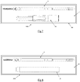
figure 1 , il est décrit un ensemble d'implantation 1 pour ostéosynthèse selon un mode de réalisation, ledit ensemble d'implantation comprenant un élément d'ancrage osseux 2 sur lequel est pré-monté de manière amovible un instrument d'entrainement 3 de l'élément d'ancrage osseux 2. - Dans ce qui suit, l'élément d'ancrage osseux 2 pourra être également désigné par le terme de vis.
- L'élément d'ancrage osseux 2 comporte une tige filetée 4 pourvue à l'une de ses extrémités 40 d'une tête 5 en forme de tulipe. La tête 5 présente ainsi une cavité longitudinale 6 taraudée débouchant dans un canal transversal 7. De manière classique en soi, le canal transversal 7 est destiné à recevoir un élément de liaison, par exemple une tige de liaison, la cavité longitudinale taraudée 6 étant destinée à recevoir un bouchon de blocage de l'élément de liaison sur la tête 5 de l'élément d'ancrage osseux 2.
- Dans le mode de réalisation décrit, l'élément d'ancrage osseux 2 est une vis multiaxiale. Plus particulièrement, la tête 5 est montée libre en rotation sur la tige filetée 4. Pour ce faire, la tige filetée 4 comporte une extrémité 40 de forme sphérique logée en partie inférieure de la tête 5, dans un espace ménagé sous le canal transversal 7 et débouchant dans ce dernier. L'espace présente une ouverture de sortie pour le passage de la tige filetée 4 lors du montage de l'élément d'ancrage osseux dans la tête 5.
- Avantageusement, une pièce formant berceau 9 est prévue au fond du canal transversal 7 de la tête 5 de vis, ladite pièce présentant un logement supérieur destiné à recevoir l'élément de liaison une fois l'instrument d'entrainement 3 retiré. La pièce formant berceau 9 présente en outre une face inférieure de forme complémentaire à celle sur laquelle elle est destinée à être placée. Dans le mode de réalisation illustré, la face inférieure présente une forme complémentaire à celle de l'extrémité 40 de la tige filetée. La pièce formant berceau 9 comporte en outre un trou traversant pour permettre le passage d'une portion de l'instrument d'entrainement 3.
- Dans le mode de réalisation décrit, l'instrument d'entrainement 3 comporte un axe d'entrainement 8 présentant une extrémité 80 agencée pour coopérer avec le fond du canal transversal 7 de la tête 5 de la vis 2. On désignera par la suite cette extrémité 80 d' « extrémité de raccordement ou d'accouplement 80 ». Dans le mode de réalisation illustré, la tête 5 et la tige filetée 4 de l'élément d'ancrage osseux 2 sont agencées l'une par rapport à l'autre de manière à ce que la tige filetée 4 débouche dans le canal transversal 7. L'axe d'entrainement 8 est alors pré-monté directement sur l'extrémité 40 de la tige filetée débouchant dans le canal transversal 7. Comme représenté sur la
figure 2 , l'extrémité 40 de la tige filetée comporte une cavité 41 de forme complémentaire avec l'extrémité de raccordement 80 de l'axe d'entrainement 8. - Avantageusement, comme illustré sur la
figure 1 , la pièce de préhension et de manipulation 8A est pourvue d'une empreinte de réception 8C d'une poignée de préhension (poignée non représentée). La présence d'une poignée a pour avantage de faciliter la manipulation de l'axe d'entrainement 8. - Afin d'améliorer la retenue de l'axe d'entrainement 8 sur l'élément d'ancrage osseux 2, l'ensemble d'implantation 1 comporte avantageusement une pièce intermédiaire de maintien disposée entre la tête 5 de l'élément d'ancrage osseux 2 et l'axe d'entrainement 8 de l'instrument. La pièce intermédiaire de maintien est arrangée avec la tête 5 et l'axe d'entrainement 8 pour maintenir ce dernier dans l'alignement de la tige filetée 4 de l'élément d'ancrage osseux 2 sur lequel l'instrument d'entrainement 3 est pré-monté.
- Avantageusement, la pièce intermédiaire de maintien est réalisée en un matériau souple, comme par exemple un élastomère. La pièce intermédiaire de maintien en élastomère présente avantageusement une section légèrement supérieure à la section de la cavité longitudinale 6 de la tête de vis 5. Ainsi, lors du montage de l'axe d'entrainement 8 sur l'élément d'ancrage osseux, la pièce intermédiaire formée de matériau souple se déforme. La pièce intermédiaire ainsi libérée permet de maintenir l'axe d'entrainement 8 couplé à l'élément d'ancrage osseux 2.
- La pièce intermédiaire de maintien est dimensionnée pour recouvrir au moins la portion de la pièce de raccordement 8B s'étendant dans la cavité longitudinale 6 lorsque l'instrument d'entrainement 3 est pré-monté sur l'élément d'ancrage osseux 2. Dans le mode de réalisation décrit, la pièce intermédiaire de maintien présente avantageusement une longueur égale à la profondeur P de la cavité longitudinale auquel s'ajoute la longueur L de la portion de l'axe d'entrainement 8 s'étendant entre l'ouverture de la cavité longitudinale 6 de la tête de vis 6 et l'extrémité 90 de la pièce de préhension 8A. En prévoyant une telle longueur de la pièce intermédiaire, il suffit de glisser la pièce intermédiaire de maintien le long de l'axe d'entrainement 8 jusqu'à venir en butée sur la face inférieure de la pièce de préhension 8A pour assurer un positionnement correct de la pièce de maintien sur l'axe. Par positionnement correct, on entend qu'une portion de la pièce intermédiaire de maintien s'étend dans la cavité longitudinale 6. Le terme « inférieur » est donné en référence aux figures. Par ailleurs, en prévoyant une mise en butée sur la pièce de préhension 8A, tout glissement de la pièce intermédiaire de maintien lors du pré-montage de l'instrument d'entrainement 3 sur l'élément d'ancrage osseux 2 est empêché.
- Avantageusement, la pièce intermédiaire de maintien est montée sur l'axe d'entrainement 8 de manière amovible.
- Outre l'implantation de l'élément d'ancrage osseux 2 dans une vertèbre, l'axe d'entrainement 8 constitue un guide pour des instruments chirurgicaux présentant un corps tubulaire. En particulier, il peut être mis en oeuvre pour guider un tube servant luimême de guide pour l'élément de liaison.
- Selon un mode de réalisation particulier non illustré, il peut être prévu un ensemble d'implantation comprenant un tube d'extension de l'élément d'ancrage osseux, ledit tube étant pré-monté sur la tête 5 de vis et traversé en son sein par l'axe d'entrainement 8. Avantageusement, le tube d'extension présente une section interne permettant le mouvement de rotation axiale de l'axe d'entrainement 8. Un tel tube est représenté non monté sur la
figure 7 (référence 30). - Comme l'illustre la
figure 7 , l'élément d'ancrage osseux 2 pré-monté de l'instrument d'entrainement 3 selon l'invention est disposé dans un emballage de conditionnement 20 stérile. Dans ce même emballage, il est prévu également un tube d'extension 30 de l'élément d'ancrage osseux apte à être monté sur l'élément d'ancrage osseux 2. De manière avantageuse, le tube de d'extension 30 est agencé pour que, lorsqu'il est couplé à la tête 5 de l'élément d'ancrage osseux 2, il est traversé par l'axe d'entrainement 8 et est agencé avec celui-ci de façon à permettre le mouvement de rotation dudit axe d'entrainement 8 autour de son axe longitudinal (axe longitudinal de l'axe d'entrainement 8). L'ensemble d'implantation et le tube d'extension 30 ainsi disposés dans un emballage de conditionnement stérile 20 forment un kit 100. Le kit 100 illustré comporte un ensemble d'implantation 1 et un tube d'extension 30. Il est bien entendu évident que le kit ne se limite pas à ces deux instruments et qu'il peut comporter plusieurs ensembles d'implantation comme plusieurs tubes de montage ou comme tout autre type d'instruments à usage unique nécessaire à une intervention chirurgicale. Selon une autre variante de réalisation non représentée, il peut être prévu de réaliser un kit comprenant un ensemble d'implantation tel que décrit précédemment sur lequel le tube d'extension est également pré-monté. Le kit pourra comprendre, comme celui décrit précédemment, tout type d'instruments à usage unique nécessaire à une intervention chirurgicale. - Selon une variante de réalisation illustrée sur la
figure 8 , il peut être prévu de réaliser un kit 110 comprenant un ensemble d'implantation 1 tel que décrit précédemment et un tube de protection ou de dilatation 21 des tissus ou un ensemble de tubes de protection/dilation emboités les uns dans les autres, et disposés dans un emballage stérile 20. Lafigure 8 illustre un ensemble d'implantation 1 et un tube ou ensemble de tubes de protection/dilatation 21 non pré-monté(s). Il peut être prévu bien entendu un kit dans lequel le ou les tubes de protection/dilation des tissus est(sont) pré-monté(s) sur l'élément d'ancrage osseux, l'axe d'entrainement traversant le(s)dit(s) tube(s). - Les
figures 4 à 6 illustrent un ensemble d'implantation 1 selon un autre mode de réalisation. Dans ce mode de réalisation, les moyens de retenue de l'axe d'entrainement 8 sur l'élément d'ancrage osseux 2, formés dans le mode de réalisation précédemment décrit par la pièce intermédiaire de maintien, sont ménagés directement sur l'axe d'entrainement 8. - Plus particulièrement, la pièce de raccordement 8B comporte deux pattes élastiques 12, 13 s'étendant de part et d'autre de son corps suivant une direction sensiblement longitudinale. Lesdites pattes 12, 13 sont arrangées de manière à venir s'enchâsser dans la cavité longitudinale 6 de la tête de vis 5 lorsque l'instrument d'entrainement 3 est pré-monté sur l'élément d'ancrage osseux 2. Afin d'assurer une retenue suffisante de l'axe d'entrainement 3 dans la tête 5 de vis, la pièce de raccordement 8B présente, au niveau de la portion d'axe délimitée par les pattes latérales 12, 13, une section externe légèrement supérieure à la section interne de la cavité longitudinale 6. Ainsi, lors du pré-montage de l'axe d'entrainement 8 sur la tête 5 de vis 2, les pattes élastiques 12, 13 sont rapprochées l'une de l'autre pour permettre l'insertion de la portion d'axe portant les pattes. Une fois relâchées, les pattes exercent une pression sur la surface interne de la cavité longitudinale 6 de la tête de vis 5, coinçant ainsi l'axe d'entrainement 3 dans la tête 2 de vis.
- Avantageusement, les pattes flexibles 12, 13 comportent respectivement un épaulement externe 14, 15, chaque épaulement étant destiné à venir en butée sur la face supérieure 50 de la tête 5 de vis. Par l'expression « épaulement externe », on entend un épaulement s'étendant dans la direction opposée à la cavité longitudinale 6 lorsque l'instrument d'entrainement 3 est pré-monté sur l'élément d'ancrage osseux 2. Le terme « supérieur » est donné en référence aux figures.
- Dans le mode de réalisation illustré sur la
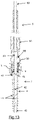
figure 5 , la pièce de raccordement 8B est représentée « pleine ». Selon un mode de réalisation avantageux, il peut être prévu que la pièce de raccordement 8B présente un canal longitudinal 83 comme la pièce de raccordement 8B représentée sur lafigure 2 . La pièce de préhension et de manipulation 8A étant elle même tubulaire, cela permet, lorsque l'instrument d'entrainement 3 est mis en oeuvre avec un élément d'ancrage osseux adapté (élément canulé avec fenêtres), d'injecter du ciment ou autre produit. Une telle configuration est illustrée sur lafigure 13 . - En complément de ces caractéristiques, l'élément d'ancrage osseux 2 comprend un alésage axial 42 s'étendant à partir de l'extrémité opposée à l'extrémité d'ancrage 45 (extrémité sphérique 40 pour le mode de réalisation illustré sur la
figure 13 ). Il comprend en outre des lumières radiales 44 communiquant avec l'alésage axial 42 (seulement six sont représentées). Dans le mode de réalisation décrit, l'alésage axial 42 présente une ouverture d'extrémité au niveau de l'extrémité 40 de la tige filetée débouchant dans la cavité 41. L'alésage axial ne présente pas en revanche d'ouverture à l'extrémité opposée à l'extrémité 40, dans le sens axial. Dans l'exemple illustré l'élément d'ancrage osseux comprend huit lumières radiales (seulement six étant représentées). Il est bien entendu évident que le nombre de lumières radiales peut varier sans sortir du cadre de l'invention. - Selon une configuration particulière, les lumières radiales 44 sont disposées par paire. Les lumières radiales de chaque paire sont disposées diamétralement opposées, tandis que chaque paire est disposée à une distance déterminée les unes des autres. Avantageusement, les paires de lumières sont disposées à distance égale les unes des autres. Selon une autre configuration non représentée, les lumières sont disposées à égale distance les unes des autres dans le sens axial et équidistantes les unes des autres de 120 degrés dans le sens radial. Il est bien entendu évident que l'invention ne se limite pas à ces configurations, le nombre et l'emplacement des lumières pouvant varier sans sortir du cadre de l'invention.
- Par ailleurs, et comme indiqué précédemment, l'instrument d'entrainement est canulé. Plus particulièrement, l'axe d'entrainement 8 est agencé pour présenter un canal de passage s'étendant sur toute la longueur dudit axe 8. Le canal est agencé de manière à communiquer, directement ou indirectement, dans l'alésage axial de l'élément d'ancrage osseux. Par communication directe, on désigne un canal de passage débouchant directement dans l'alésage axial de l'élément d'ancrage osseux; par communication indirecte, on entend un canal de passage communiquant avec l'alésage axial de l'élément d'ange osseux par l'intermédiaire d'une cavité : l'extrémité de raccordement 80 n'est pas enchâssée jusqu'au fond de la cavité 41 ménagée à l'extrémité 40 sphérique de l'élément d'ancrage osseux. De ce fait, le canal de passage débouche dans une portion de la cavité 41 qui elle-même communique avec l'alésage axial 42.
- Avantageusement, l'injection de ciment ou autre substance est réalisée à l'aide d'une canule 60 insérée dans le canal de passage de l'axe d'entrainement. La
figure 13 montre une vue partielle de la canule 60 montée dans le canal. Il est bien entendu évident qu'il s'agit d'un mode de réalisation particulier d'injection de substances. Le recours à une canule n'est en effet pas indispensable, le ciment et les autres substances pouvant être injectés directement dans le canal de passage. - Comme dans les modes de réalisation précédemment décrits, l'ensemble d'implantation illustré sur la
figure 13 est disposé dans un emballage de conditionnement 20 stérile. Dans ce même emballage, il pourra être prévu également un ou plusieurs tube(s) d'extension de l'élément d'ancrage osseux apte à être monté sur l'élément d'ancrage osseux, un ou plusieurs tube(s) de protection ou de dilatation des tissus ou tout autre type d'instruments à usage unique nécessaire à une intervention chirurgicale de sorte à former un kit. - L'invention est décrite dans ce qui précède à titre d'exemple. Il est entendu que l'homme du métier est à même de réaliser différentes variantes de réalisation de l'invention sans pour autant sortir du cadre de l'invention.
Claims (1)
- Ensemble d'implantation (1) comprenant un élément d'ancrage osseux (2) comportant une tige filetée (4) pourvue à l'une de ses extrémités d'une tête (5), la tige filetée (4) comprenant un alésage axial (42) présentant une ouverture d'extrémité au niveau de la tête (5) et au moins une lumière radiale (44) communiquant avec l'alésage axial (42), l'élément d'ancrage osseux (2) étant pourvu solidairement d'un axe amovible, traversé longitudinalement par un canal de passage communiquant avec l'alésage axial (42) de l'élément d'ancrage osseux pour l'injection de substances, ledit axe constituant un axe d'entrainement (8) d'un instrument d'entrainement (3) de l'élément d'ancrage osseux,
caractérisé en ce que• ledit axe d'entrainement (8) comporte deux pattes flexibles (12, 13) s'étendant longitudinalement, lesdites pattes (12, 13) formant des moyens de retenue axiale dudit axe d'entrainement (8) sur ledit élément d'ancrage osseux (2)• et en ce que ledit élément d'ancrage osseux (2) pourvu dudit axe est disposé dans un emballage scellé de conditionnement stérile (20).
Applications Claiming Priority (2)
| Application Number | Priority Date | Filing Date | Title |
|---|---|---|---|
| FR1350989A FR3001628B1 (fr) | 2013-02-05 | 2013-02-05 | Ensemble d'implantation comprenant un instrument d'entrainement pre-monte sur un implant osseux. |
| PCT/FR2014/050214 WO2014122395A1 (fr) | 2013-02-05 | 2014-02-05 | Ensemble d'implantation comprenant un instrument d'entraînement pre-monté sur un implant osseux |
Publications (3)
| Publication Number | Publication Date |
|---|---|
| EP2953564A1 EP2953564A1 (fr) | 2015-12-16 |
| EP2953564B1 EP2953564B1 (fr) | 2018-08-01 |
| EP2953564B2 true EP2953564B2 (fr) | 2022-07-27 |
Family
ID=48652220
Family Applications (1)
| Application Number | Title | Priority Date | Filing Date |
|---|---|---|---|
| EP14706889.4A Active EP2953564B2 (fr) | 2013-02-05 | 2014-02-05 | Ensemble d'implantation comprenant un instrument d'entraînement pre-monté sur un implant osseux |
Country Status (5)
| Country | Link |
|---|---|
| US (1) | US10835299B2 (fr) |
| EP (1) | EP2953564B2 (fr) |
| ES (1) | ES2688694T5 (fr) |
| FR (1) | FR3001628B1 (fr) |
| WO (1) | WO2014122395A1 (fr) |
Families Citing this family (10)
| Publication number | Priority date | Publication date | Assignee | Title |
|---|---|---|---|---|
| US10799300B2 (en) * | 2018-10-18 | 2020-10-13 | Warsaw Orthopedic, Inc. | Spinal implant system and method |
| FR3094887B1 (fr) | 2019-04-09 | 2023-05-19 | Safe Orthopaedics | Systeme pour la restauration en hauteur d’une vertebre affaissee |
| US11660134B2 (en) | 2019-06-13 | 2023-05-30 | Medos International Sarl | Instruments and methods for delivering bone cement to a bone screw |
| US11325231B2 (en) * | 2019-11-22 | 2022-05-10 | DePuy Synthes Products, Inc. | Self-retaining screwdriver with engaging tip feature |
| US12004782B2 (en) | 2020-03-26 | 2024-06-11 | Warsaw Orthopedic, Inc. | Instrument for locking orthopedic screws |
| US11627998B2 (en) | 2020-12-11 | 2023-04-18 | Warsaw Orthopedic, Inc. | Head position and driver combination instrument |
| US11291477B1 (en) | 2021-05-04 | 2022-04-05 | Warsaw Orthopedic, Inc. | Dorsal adjusting implant and methods of use |
| US11432848B1 (en) | 2021-05-12 | 2022-09-06 | Warsaw Orthopedic, Inc. | Top loading quick lock construct |
| US11712270B2 (en) | 2021-05-17 | 2023-08-01 | Warsaw Orthopedic, Inc. | Quick lock clamp constructs and associated methods |
| US11957391B2 (en) | 2021-11-01 | 2024-04-16 | Warsaw Orthopedic, Inc. | Bone screw having an overmold of a shank |
Citations (1)
| Publication number | Priority date | Publication date | Assignee | Title |
|---|---|---|---|---|
| US20090264895A1 (en) † | 2008-04-22 | 2009-10-22 | Warsaw Orthopedic, Inc. | Systems and methods for implanting a bone fastener and delivering a bone filling material |
Family Cites Families (19)
| Publication number | Priority date | Publication date | Assignee | Title |
|---|---|---|---|---|
| US6269716B1 (en) * | 1998-11-18 | 2001-08-07 | Macropore, Inc. | High-torque resorbable screws |
| FR2820630A1 (fr) | 2001-02-15 | 2002-08-16 | Karim Benazzouz | Dispositif pour vehiculer un substitut osseux ou du ciment au niveau d'une instabilite osseuse, et instrument pour la mise en oeuvre de ce dispositif |
| FR2839640B1 (fr) * | 2002-05-14 | 2005-04-01 | Xavier Renard | Vis osseuse |
| US7476228B2 (en) * | 2002-10-11 | 2009-01-13 | Abdou M Samy | Distraction screw for skeletal surgery and method of use |
| US20050033430A1 (en) | 2003-08-05 | 2005-02-10 | Russell Powers | Surgical kit and method for providing sterilized equipment for use in spinal surgery |
| US7967826B2 (en) * | 2003-10-21 | 2011-06-28 | Theken Spine, Llc | Connector transfer tool for internal structure stabilization systems |
| US7559943B2 (en) * | 2004-06-09 | 2009-07-14 | Zimmer Spine, Inc. | Spinal fixation device with internal drive structure |
| DE102005027400A1 (de) * | 2005-06-13 | 2006-12-14 | Heraeus Kulzer Gmbh | Verfahren zur Aufnahme eines medizinischen Elements an einer Handhabungsvorrichtung, Handhabungsvorrichtung für ein medizinisches Element und medizinisches Implantat |
| US7846093B2 (en) | 2005-09-26 | 2010-12-07 | K2M, Inc. | Minimally invasive retractor and methods of use |
| US8221426B2 (en) | 2008-02-12 | 2012-07-17 | Warsaw Orthopedic, Inc. | Methods and devices for deformity correction |
| US8747407B2 (en) | 2008-02-28 | 2014-06-10 | K2M, Inc. | Minimally invasive retractor and methods of use |
| AU2009308866B2 (en) | 2008-10-30 | 2015-03-12 | Depuy Spine, Inc. | Systems and methods for delivering bone cement to a bone anchor |
| EP2727546A3 (fr) * | 2009-08-20 | 2014-07-30 | Biedermann Technologies GmbH & Co. KG | Dispositif d'ancrage d'os, outil et procédé d'assemblage de celui-ci et outil destiné à être utilisé avec celui-ci. |
| US8747411B2 (en) | 2009-09-30 | 2014-06-10 | Michael David Mitchell | Fluid delivery and bone screw driver apparatus |
| US8262670B2 (en) * | 2009-10-28 | 2012-09-11 | Aesculap Implant Systems, Llc | Self-retaining surgical driver |
| FR2954689B1 (fr) | 2009-12-28 | 2012-12-21 | Sterispine | Dispositif et methode pour la chirurgie rachidienne. |
| US8535318B2 (en) | 2010-04-23 | 2013-09-17 | DePuy Synthes Products, LLC | Minimally invasive instrument set, devices and related methods |
| US8394108B2 (en) * | 2010-06-18 | 2013-03-12 | Spine Wave, Inc. | Screw driver for a multiaxial bone screw |
| US8945193B2 (en) | 2010-07-20 | 2015-02-03 | X-Spine Systems, Inc. | Minimally invasive spinal facet compression screw and system for bone joint fusion and fixation |
-
2013
- 2013-02-05 FR FR1350989A patent/FR3001628B1/fr not_active Expired - Fee Related
-
2014
- 2014-02-05 US US14/765,384 patent/US10835299B2/en active Active
- 2014-02-05 EP EP14706889.4A patent/EP2953564B2/fr active Active
- 2014-02-05 WO PCT/FR2014/050214 patent/WO2014122395A1/fr not_active Ceased
- 2014-02-05 ES ES14706889T patent/ES2688694T5/es active Active
Patent Citations (1)
| Publication number | Priority date | Publication date | Assignee | Title |
|---|---|---|---|---|
| US20090264895A1 (en) † | 2008-04-22 | 2009-10-22 | Warsaw Orthopedic, Inc. | Systems and methods for implanting a bone fastener and delivering a bone filling material |
Also Published As
| Publication number | Publication date |
|---|---|
| ES2688694T3 (es) | 2018-11-06 |
| WO2014122395A1 (fr) | 2014-08-14 |
| EP2953564A1 (fr) | 2015-12-16 |
| EP2953564B1 (fr) | 2018-08-01 |
| US10835299B2 (en) | 2020-11-17 |
| FR3001628A1 (fr) | 2014-08-08 |
| US20150374417A1 (en) | 2015-12-31 |
| ES2688694T5 (es) | 2022-11-29 |
| FR3001628B1 (fr) | 2017-11-24 |
Similar Documents
| Publication | Publication Date | Title |
|---|---|---|
| EP2953564B2 (fr) | Ensemble d'implantation comprenant un instrument d'entraînement pre-monté sur un implant osseux | |
| CA2321895C (fr) | Dispositif orthopedique monolateral de fixation externe | |
| EP2526888B2 (fr) | Dispositif pour la chirurgie rachidienne. | |
| EP3119298B1 (fr) | Ensemble chirurgical, vis d'ancrage osseux et dispositif d'extension d'une telle vis faisant parties dudit ensemble chirurgical | |
| FR2459650A1 (fr) | Dispositif intramedullaire de compression pour fracture des os | |
| FR2831049A1 (fr) | Plaque pour dispositif d'osteosynthese et procede de premontage | |
| FR2831048A1 (fr) | Dispositif d'osteosynthese a approche progressive et procede de premontage | |
| EP2874552B1 (fr) | Dispositif de guidage d'un instrument chirurgical en position sur un element d'ancrage osseux comprenant des moyens de realignement d'une tige de liaison avec l'element d'ancrage et systeme d'instrumentation chirurgical associe | |
| FR2887434A1 (fr) | Materiel de traitement chirurgical de deux vertebres | |
| FR2927791A1 (fr) | Prothese articulaire posterieure lombaire a rotule | |
| EP2833808A1 (fr) | Kit d'intrumentation d'osteosynthèse rachidienne | |
| EP2854674B1 (fr) | Systeme d'instrumentation pour la realisation d'une intervention chirurgicale sur des vertebres comprenant des moyens de blocage temporaire | |
| FR2959113A1 (fr) | Vis pediculaire polaxiale et dispositif de fixation pediculaire en faisant application, pour osteosynthese vertebrale | |
| FR2930719A1 (fr) | Crochet pour dispositif d'osteosynthese vertebrale et dispositif le comprenant | |
| FR2920663A1 (fr) | Instrument d'aide a la pose d'un systeme d'osteosynthese. | |
| FR2790941A1 (fr) | Instrumentation d'osteosynthese rachidienne a plaque et vis pediculaire ou a connecteur transversal entre une tige vertebrale et une vis pediculaire | |
| EP2184083B1 (fr) | Dispositif de fixation transcranien pour sondes de stimulation cérébrale profonde | |
| EP3209228A1 (fr) | Dispositif d'ancrage vertebral multiaxial pour le redressement d'une vertebre | |
| EP0779796A1 (fr) | Dispositif d'osteosynthese rachidienne | |
| EP3116426A1 (fr) | Systeme d'osteosynthese comprenant des moyens de redressement d'un element d'ancrage osseux par rapport a une tete de vis et vis d'ancrage mise en oeuvre dans un tel systeme | |
| WO2018024617A1 (fr) | Implant deployable | |
| EP3565491B1 (fr) | Vis osseuse pour dispositif d'ostéosynthèse, ensemble formé par une vis, un connecteur et un écrou, et kit comportant au moins un tel ensemble | |
| EP3952770B1 (fr) | Ensemble de positionnement et de blocage en position d'un ballonnet gonflable au sein d'un corps vertebral | |
| FR2913330A1 (fr) | Dispositif d'ancrage vertebral par clou intrapediculaire | |
| FR3076199A1 (fr) | Systeme pour relier deux portions d'os entre elles quand l'une doit se deplacer par rapport a l'autre |
Legal Events
| Date | Code | Title | Description |
|---|---|---|---|
| PUAI | Public reference made under article 153(3) epc to a published international application that has entered the european phase |
Free format text: ORIGINAL CODE: 0009012 |
|
| 17P | Request for examination filed |
Effective date: 20150731 |
|
| AK | Designated contracting states |
Kind code of ref document: A1 Designated state(s): AL AT BE BG CH CY CZ DE DK EE ES FI FR GB GR HR HU IE IS IT LI LT LU LV MC MK MT NL NO PL PT RO RS SE SI SK SM TR |
|
| AX | Request for extension of the european patent |
Extension state: BA ME |
|
| DAX | Request for extension of the european patent (deleted) | ||
| STAA | Information on the status of an ep patent application or granted ep patent |
Free format text: STATUS: EXAMINATION IS IN PROGRESS |
|
| 17Q | First examination report despatched |
Effective date: 20170301 |
|
| GRAP | Despatch of communication of intention to grant a patent |
Free format text: ORIGINAL CODE: EPIDOSNIGR1 |
|
| STAA | Information on the status of an ep patent application or granted ep patent |
Free format text: STATUS: GRANT OF PATENT IS INTENDED |
|
| INTG | Intention to grant announced |
Effective date: 20180509 |
|
| RIN1 | Information on inventor provided before grant (corrected) |
Inventor name: MAESTRETTI, GIANLUCA Inventor name: DELAHAYE, CONSTANT Inventor name: PETIT, DOMINIQUE Inventor name: FUENTES, STEPHANE |
|
| GRAS | Grant fee paid |
Free format text: ORIGINAL CODE: EPIDOSNIGR3 |
|
| GRAA | (expected) grant |
Free format text: ORIGINAL CODE: 0009210 |
|
| STAA | Information on the status of an ep patent application or granted ep patent |
Free format text: STATUS: THE PATENT HAS BEEN GRANTED |
|
| AK | Designated contracting states |
Kind code of ref document: B1 Designated state(s): AL AT BE BG CH CY CZ DE DK EE ES FI FR GB GR HR HU IE IS IT LI LT LU LV MC MK MT NL NO PL PT RO RS SE SI SK SM TR |
|
| REG | Reference to a national code |
Ref country code: GB Ref legal event code: FG4D Free format text: NOT ENGLISH |
|
| REG | Reference to a national code |
Ref country code: CH Ref legal event code: EP Ref country code: AT Ref legal event code: REF Ref document number: 1023396 Country of ref document: AT Kind code of ref document: T Effective date: 20180815 |
|
| REG | Reference to a national code |
Ref country code: IE Ref legal event code: FG4D Free format text: LANGUAGE OF EP DOCUMENT: FRENCH |
|
| REG | Reference to a national code |
Ref country code: DE Ref legal event code: R096 Ref document number: 602014029475 Country of ref document: DE |
|
| REG | Reference to a national code |
Ref country code: CH Ref legal event code: NV Representative=s name: ABREMA AGENCE BREVET ET MARQUES, GANGUILLET, CH |
|
| REG | Reference to a national code |
Ref country code: ES Ref legal event code: FG2A Ref document number: 2688694 Country of ref document: ES Kind code of ref document: T3 Effective date: 20181106 |
|
| REG | Reference to a national code |
Ref country code: NL Ref legal event code: MP Effective date: 20180801 |
|
| REG | Reference to a national code |
Ref country code: LT Ref legal event code: MG4D |
|
| REG | Reference to a national code |
Ref country code: AT Ref legal event code: MK05 Ref document number: 1023396 Country of ref document: AT Kind code of ref document: T Effective date: 20180801 |
|
| PG25 | Lapsed in a contracting state [announced via postgrant information from national office to epo] |
Ref country code: FI Free format text: LAPSE BECAUSE OF FAILURE TO SUBMIT A TRANSLATION OF THE DESCRIPTION OR TO PAY THE FEE WITHIN THE PRESCRIBED TIME-LIMIT Effective date: 20180801 Ref country code: GR Free format text: LAPSE BECAUSE OF FAILURE TO SUBMIT A TRANSLATION OF THE DESCRIPTION OR TO PAY THE FEE WITHIN THE PRESCRIBED TIME-LIMIT Effective date: 20181102 Ref country code: NO Free format text: LAPSE BECAUSE OF FAILURE TO SUBMIT A TRANSLATION OF THE DESCRIPTION OR TO PAY THE FEE WITHIN THE PRESCRIBED TIME-LIMIT Effective date: 20181101 Ref country code: IS Free format text: LAPSE BECAUSE OF FAILURE TO SUBMIT A TRANSLATION OF THE DESCRIPTION OR TO PAY THE FEE WITHIN THE PRESCRIBED TIME-LIMIT Effective date: 20181201 Ref country code: RS Free format text: LAPSE BECAUSE OF FAILURE TO SUBMIT A TRANSLATION OF THE DESCRIPTION OR TO PAY THE FEE WITHIN THE PRESCRIBED TIME-LIMIT Effective date: 20180801 Ref country code: AT Free format text: LAPSE BECAUSE OF FAILURE TO SUBMIT A TRANSLATION OF THE DESCRIPTION OR TO PAY THE FEE WITHIN THE PRESCRIBED TIME-LIMIT Effective date: 20180801 Ref country code: LT Free format text: LAPSE BECAUSE OF FAILURE TO SUBMIT A TRANSLATION OF THE DESCRIPTION OR TO PAY THE FEE WITHIN THE PRESCRIBED TIME-LIMIT Effective date: 20180801 Ref country code: SE Free format text: LAPSE BECAUSE OF FAILURE TO SUBMIT A TRANSLATION OF THE DESCRIPTION OR TO PAY THE FEE WITHIN THE PRESCRIBED TIME-LIMIT Effective date: 20180801 Ref country code: NL Free format text: LAPSE BECAUSE OF FAILURE TO SUBMIT A TRANSLATION OF THE DESCRIPTION OR TO PAY THE FEE WITHIN THE PRESCRIBED TIME-LIMIT Effective date: 20180801 Ref country code: BG Free format text: LAPSE BECAUSE OF FAILURE TO SUBMIT A TRANSLATION OF THE DESCRIPTION OR TO PAY THE FEE WITHIN THE PRESCRIBED TIME-LIMIT Effective date: 20181101 Ref country code: PL Free format text: LAPSE BECAUSE OF FAILURE TO SUBMIT A TRANSLATION OF THE DESCRIPTION OR TO PAY THE FEE WITHIN THE PRESCRIBED TIME-LIMIT Effective date: 20180801 |
|
| PG25 | Lapsed in a contracting state [announced via postgrant information from national office to epo] |
Ref country code: AL Free format text: LAPSE BECAUSE OF FAILURE TO SUBMIT A TRANSLATION OF THE DESCRIPTION OR TO PAY THE FEE WITHIN THE PRESCRIBED TIME-LIMIT Effective date: 20180801 Ref country code: LV Free format text: LAPSE BECAUSE OF FAILURE TO SUBMIT A TRANSLATION OF THE DESCRIPTION OR TO PAY THE FEE WITHIN THE PRESCRIBED TIME-LIMIT Effective date: 20180801 Ref country code: HR Free format text: LAPSE BECAUSE OF FAILURE TO SUBMIT A TRANSLATION OF THE DESCRIPTION OR TO PAY THE FEE WITHIN THE PRESCRIBED TIME-LIMIT Effective date: 20180801 |
|
| REG | Reference to a national code |
Ref country code: DE Ref legal event code: R026 Ref document number: 602014029475 Country of ref document: DE |
|
| PLBI | Opposition filed |
Free format text: ORIGINAL CODE: 0009260 |
|
| PG25 | Lapsed in a contracting state [announced via postgrant information from national office to epo] |
Ref country code: RO Free format text: LAPSE BECAUSE OF FAILURE TO SUBMIT A TRANSLATION OF THE DESCRIPTION OR TO PAY THE FEE WITHIN THE PRESCRIBED TIME-LIMIT Effective date: 20180801 Ref country code: CZ Free format text: LAPSE BECAUSE OF FAILURE TO SUBMIT A TRANSLATION OF THE DESCRIPTION OR TO PAY THE FEE WITHIN THE PRESCRIBED TIME-LIMIT Effective date: 20180801 Ref country code: EE Free format text: LAPSE BECAUSE OF FAILURE TO SUBMIT A TRANSLATION OF THE DESCRIPTION OR TO PAY THE FEE WITHIN THE PRESCRIBED TIME-LIMIT Effective date: 20180801 |
|
| 26 | Opposition filed |
Opponent name: NEO MEDICAL SA Effective date: 20190411 |
|
| PLAX | Notice of opposition and request to file observation + time limit sent |
Free format text: ORIGINAL CODE: EPIDOSNOBS2 |
|
| PG25 | Lapsed in a contracting state [announced via postgrant information from national office to epo] |
Ref country code: DK Free format text: LAPSE BECAUSE OF FAILURE TO SUBMIT A TRANSLATION OF THE DESCRIPTION OR TO PAY THE FEE WITHIN THE PRESCRIBED TIME-LIMIT Effective date: 20180801 Ref country code: SM Free format text: LAPSE BECAUSE OF FAILURE TO SUBMIT A TRANSLATION OF THE DESCRIPTION OR TO PAY THE FEE WITHIN THE PRESCRIBED TIME-LIMIT Effective date: 20180801 Ref country code: SK Free format text: LAPSE BECAUSE OF FAILURE TO SUBMIT A TRANSLATION OF THE DESCRIPTION OR TO PAY THE FEE WITHIN THE PRESCRIBED TIME-LIMIT Effective date: 20180801 |
|
| PG25 | Lapsed in a contracting state [announced via postgrant information from national office to epo] |
Ref country code: SI Free format text: LAPSE BECAUSE OF FAILURE TO SUBMIT A TRANSLATION OF THE DESCRIPTION OR TO PAY THE FEE WITHIN THE PRESCRIBED TIME-LIMIT Effective date: 20180801 |
|
| PLBB | Reply of patent proprietor to notice(s) of opposition received |
Free format text: ORIGINAL CODE: EPIDOSNOBS3 |
|
| PG25 | Lapsed in a contracting state [announced via postgrant information from national office to epo] |
Ref country code: MC Free format text: LAPSE BECAUSE OF FAILURE TO SUBMIT A TRANSLATION OF THE DESCRIPTION OR TO PAY THE FEE WITHIN THE PRESCRIBED TIME-LIMIT Effective date: 20180801 Ref country code: LU Free format text: LAPSE BECAUSE OF NON-PAYMENT OF DUE FEES Effective date: 20190205 |
|
| REG | Reference to a national code |
Ref country code: BE Ref legal event code: MM Effective date: 20190228 |
|
| REG | Reference to a national code |
Ref country code: IE Ref legal event code: MM4A |
|
| PG25 | Lapsed in a contracting state [announced via postgrant information from national office to epo] |
Ref country code: IE Free format text: LAPSE BECAUSE OF NON-PAYMENT OF DUE FEES Effective date: 20190205 |
|
| PG25 | Lapsed in a contracting state [announced via postgrant information from national office to epo] |
Ref country code: BE Free format text: LAPSE BECAUSE OF NON-PAYMENT OF DUE FEES Effective date: 20190228 |
|
| PG25 | Lapsed in a contracting state [announced via postgrant information from national office to epo] |
Ref country code: TR Free format text: LAPSE BECAUSE OF FAILURE TO SUBMIT A TRANSLATION OF THE DESCRIPTION OR TO PAY THE FEE WITHIN THE PRESCRIBED TIME-LIMIT Effective date: 20180801 |
|
| PG25 | Lapsed in a contracting state [announced via postgrant information from national office to epo] |
Ref country code: PT Free format text: LAPSE BECAUSE OF FAILURE TO SUBMIT A TRANSLATION OF THE DESCRIPTION OR TO PAY THE FEE WITHIN THE PRESCRIBED TIME-LIMIT Effective date: 20181201 Ref country code: MT Free format text: LAPSE BECAUSE OF FAILURE TO SUBMIT A TRANSLATION OF THE DESCRIPTION OR TO PAY THE FEE WITHIN THE PRESCRIBED TIME-LIMIT Effective date: 20180801 |
|
| REG | Reference to a national code |
Ref country code: CH Ref legal event code: PFUS Owner name: SAFE ORTHOPAEDICS, FR Free format text: FORMER OWNER: SAFE ORTHOPAEDICS, FR |
|
| PG25 | Lapsed in a contracting state [announced via postgrant information from national office to epo] |
Ref country code: CY Free format text: LAPSE BECAUSE OF FAILURE TO SUBMIT A TRANSLATION OF THE DESCRIPTION OR TO PAY THE FEE WITHIN THE PRESCRIBED TIME-LIMIT Effective date: 20180801 |
|
| PG25 | Lapsed in a contracting state [announced via postgrant information from national office to epo] |
Ref country code: HU Free format text: LAPSE BECAUSE OF FAILURE TO SUBMIT A TRANSLATION OF THE DESCRIPTION OR TO PAY THE FEE WITHIN THE PRESCRIBED TIME-LIMIT; INVALID AB INITIO Effective date: 20140205 |
|
| PGFP | Annual fee paid to national office [announced via postgrant information from national office to epo] |
Ref country code: ES Payment date: 20220308 Year of fee payment: 9 |
|
| PUAH | Patent maintained in amended form |
Free format text: ORIGINAL CODE: 0009272 |
|
| STAA | Information on the status of an ep patent application or granted ep patent |
Free format text: STATUS: PATENT MAINTAINED AS AMENDED |
|
| PG25 | Lapsed in a contracting state [announced via postgrant information from national office to epo] |
Ref country code: MK Free format text: LAPSE BECAUSE OF FAILURE TO SUBMIT A TRANSLATION OF THE DESCRIPTION OR TO PAY THE FEE WITHIN THE PRESCRIBED TIME-LIMIT Effective date: 20180801 |
|
| 27A | Patent maintained in amended form |
Effective date: 20220727 |
|
| AK | Designated contracting states |
Kind code of ref document: B2 Designated state(s): AL AT BE BG CH CY CZ DE DK EE ES FI FR GB GR HR HU IE IS IT LI LT LU LV MC MK MT NL NO PL PT RO RS SE SI SK SM TR |
|
| REG | Reference to a national code |
Ref country code: DE Ref legal event code: R102 Ref document number: 602014029475 Country of ref document: DE |
|
| REG | Reference to a national code |
Ref country code: ES Ref legal event code: DC2A Ref document number: 2688694 Country of ref document: ES Kind code of ref document: T5 Effective date: 20221129 |
|
| PGFP | Annual fee paid to national office [announced via postgrant information from national office to epo] |
Ref country code: FR Payment date: 20230221 Year of fee payment: 10 Ref country code: CH Payment date: 20230307 Year of fee payment: 10 |
|
| PGFP | Annual fee paid to national office [announced via postgrant information from national office to epo] |
Ref country code: IT Payment date: 20230223 Year of fee payment: 10 Ref country code: GB Payment date: 20230221 Year of fee payment: 10 Ref country code: DE Payment date: 20230216 Year of fee payment: 10 |
|
| REG | Reference to a national code |
Ref country code: ES Ref legal event code: FD2A Effective date: 20240404 |
|
| PG25 | Lapsed in a contracting state [announced via postgrant information from national office to epo] |
Ref country code: ES Free format text: LAPSE BECAUSE OF NON-PAYMENT OF DUE FEES Effective date: 20230206 |
|
| PG25 | Lapsed in a contracting state [announced via postgrant information from national office to epo] |
Ref country code: ES Free format text: LAPSE BECAUSE OF NON-PAYMENT OF DUE FEES Effective date: 20230206 |
|
| REG | Reference to a national code |
Ref country code: DE Ref legal event code: R119 Ref document number: 602014029475 Country of ref document: DE |
|
| REG | Reference to a national code |
Ref country code: CH Ref legal event code: PL |
|
| PG25 | Lapsed in a contracting state [announced via postgrant information from national office to epo] |
Ref country code: CH Free format text: LAPSE BECAUSE OF NON-PAYMENT OF DUE FEES Effective date: 20240229 |
|
| GBPC | Gb: european patent ceased through non-payment of renewal fee |
Effective date: 20240205 |
|
| PG25 | Lapsed in a contracting state [announced via postgrant information from national office to epo] |
Ref country code: CH Free format text: LAPSE BECAUSE OF NON-PAYMENT OF DUE FEES Effective date: 20240229 |
|
| PG25 | Lapsed in a contracting state [announced via postgrant information from national office to epo] |
Ref country code: DE Free format text: LAPSE BECAUSE OF NON-PAYMENT OF DUE FEES Effective date: 20240903 |
|
| PG25 | Lapsed in a contracting state [announced via postgrant information from national office to epo] |
Ref country code: GB Free format text: LAPSE BECAUSE OF NON-PAYMENT OF DUE FEES Effective date: 20240205 |
|
| PG25 | Lapsed in a contracting state [announced via postgrant information from national office to epo] |
Ref country code: FR Free format text: LAPSE BECAUSE OF NON-PAYMENT OF DUE FEES Effective date: 20240229 |
|
| PG25 | Lapsed in a contracting state [announced via postgrant information from national office to epo] |
Ref country code: GB Free format text: LAPSE BECAUSE OF NON-PAYMENT OF DUE FEES Effective date: 20240205 Ref country code: FR Free format text: LAPSE BECAUSE OF NON-PAYMENT OF DUE FEES Effective date: 20240229 Ref country code: DE Free format text: LAPSE BECAUSE OF NON-PAYMENT OF DUE FEES Effective date: 20240903 |
|
| PG25 | Lapsed in a contracting state [announced via postgrant information from national office to epo] |
Ref country code: IT Free format text: LAPSE BECAUSE OF NON-PAYMENT OF DUE FEES Effective date: 20240205 |