EP2953287B1 - Procédé et appareil permettant de transmettre un accusé de réception dans un système de communication sans fil - Google Patents
Procédé et appareil permettant de transmettre un accusé de réception dans un système de communication sans fil Download PDFInfo
- Publication number
- EP2953287B1 EP2953287B1 EP14745669.3A EP14745669A EP2953287B1 EP 2953287 B1 EP2953287 B1 EP 2953287B1 EP 14745669 A EP14745669 A EP 14745669A EP 2953287 B1 EP2953287 B1 EP 2953287B1
- Authority
- EP
- European Patent Office
- Prior art keywords
- subframe
- ecce
- pucch
- ack
- aro
- Prior art date
- Legal status (The legal status is an assumption and is not a legal conclusion. Google has not performed a legal analysis and makes no representation as to the accuracy of the status listed.)
- Active
Links
- 238000000034 method Methods 0.000 title claims description 21
- 238000004891 communication Methods 0.000 title claims description 20
- 230000005540 biological transmission Effects 0.000 claims description 73
- 230000004044 response Effects 0.000 claims description 39
- 230000007774 longterm Effects 0.000 claims description 5
- 101000741965 Homo sapiens Inactive tyrosine-protein kinase PRAG1 Proteins 0.000 description 120
- 102100038659 Inactive tyrosine-protein kinase PRAG1 Human genes 0.000 description 120
- 230000007480 spreading Effects 0.000 description 19
- 238000010586 diagram Methods 0.000 description 9
- 230000011664 signaling Effects 0.000 description 9
- 238000013468 resource allocation Methods 0.000 description 8
- 230000006870 function Effects 0.000 description 7
- 238000005259 measurement Methods 0.000 description 7
- 108010003272 Hyaluronate lyase Proteins 0.000 description 6
- 101001056707 Homo sapiens Proepiregulin Proteins 0.000 description 5
- 102100025498 Proepiregulin Human genes 0.000 description 5
- 125000004122 cyclic group Chemical group 0.000 description 5
- 230000002776 aggregation Effects 0.000 description 4
- 238000004220 aggregation Methods 0.000 description 4
- 230000001427 coherent effect Effects 0.000 description 4
- 238000000794 confocal Raman spectroscopy Methods 0.000 description 4
- 238000011500 cytoreductive surgery Methods 0.000 description 4
- 238000005516 engineering process Methods 0.000 description 4
- 238000013507 mapping Methods 0.000 description 4
- 230000008569 process Effects 0.000 description 4
- 239000002699 waste material Substances 0.000 description 4
- 230000008859 change Effects 0.000 description 3
- 230000008901 benefit Effects 0.000 description 2
- 230000000694 effects Effects 0.000 description 2
- 238000010295 mobile communication Methods 0.000 description 2
- 238000012986 modification Methods 0.000 description 2
- 230000004048 modification Effects 0.000 description 2
- 230000000737 periodic effect Effects 0.000 description 2
- 230000010363 phase shift Effects 0.000 description 2
- 201000000913 Duane retraction syndrome Diseases 0.000 description 1
- 108010076504 Protein Sorting Signals Proteins 0.000 description 1
- 230000004913 activation Effects 0.000 description 1
- 230000004931 aggregating effect Effects 0.000 description 1
- 238000003491 array Methods 0.000 description 1
- 230000015556 catabolic process Effects 0.000 description 1
- 230000001413 cellular effect Effects 0.000 description 1
- 230000006835 compression Effects 0.000 description 1
- 238000007906 compression Methods 0.000 description 1
- 238000006731 degradation reaction Methods 0.000 description 1
- 238000013461 design Methods 0.000 description 1
- 238000001514 detection method Methods 0.000 description 1
- 238000000162 direct recoil spectroscopy Methods 0.000 description 1
- 239000011159 matrix material Substances 0.000 description 1
- 238000012544 monitoring process Methods 0.000 description 1
- 238000012545 processing Methods 0.000 description 1
- 230000009467 reduction Effects 0.000 description 1
Images


Classifications
-
- H—ELECTRICITY
- H04—ELECTRIC COMMUNICATION TECHNIQUE
- H04W—WIRELESS COMMUNICATION NETWORKS
- H04W72/00—Local resource management
- H04W72/20—Control channels or signalling for resource management
- H04W72/21—Control channels or signalling for resource management in the uplink direction of a wireless link, i.e. towards the network
-
- H—ELECTRICITY
- H04—ELECTRIC COMMUNICATION TECHNIQUE
- H04L—TRANSMISSION OF DIGITAL INFORMATION, e.g. TELEGRAPHIC COMMUNICATION
- H04L1/00—Arrangements for detecting or preventing errors in the information received
- H04L1/12—Arrangements for detecting or preventing errors in the information received by using return channel
- H04L1/16—Arrangements for detecting or preventing errors in the information received by using return channel in which the return channel carries supervisory signals, e.g. repetition request signals
- H04L1/1607—Details of the supervisory signal
- H04L1/1621—Group acknowledgement, i.e. the acknowledgement message defining a range of identifiers, e.g. of sequence numbers
-
- H—ELECTRICITY
- H04—ELECTRIC COMMUNICATION TECHNIQUE
- H04L—TRANSMISSION OF DIGITAL INFORMATION, e.g. TELEGRAPHIC COMMUNICATION
- H04L1/00—Arrangements for detecting or preventing errors in the information received
- H04L1/12—Arrangements for detecting or preventing errors in the information received by using return channel
- H04L1/16—Arrangements for detecting or preventing errors in the information received by using return channel in which the return channel carries supervisory signals, e.g. repetition request signals
- H04L1/18—Automatic repetition systems, e.g. Van Duuren systems
- H04L1/1829—Arrangements specially adapted for the receiver end
- H04L1/1854—Scheduling and prioritising arrangements
-
- H—ELECTRICITY
- H04—ELECTRIC COMMUNICATION TECHNIQUE
- H04L—TRANSMISSION OF DIGITAL INFORMATION, e.g. TELEGRAPHIC COMMUNICATION
- H04L1/00—Arrangements for detecting or preventing errors in the information received
- H04L1/12—Arrangements for detecting or preventing errors in the information received by using return channel
- H04L1/16—Arrangements for detecting or preventing errors in the information received by using return channel in which the return channel carries supervisory signals, e.g. repetition request signals
- H04L1/18—Automatic repetition systems, e.g. Van Duuren systems
- H04L1/1829—Arrangements specially adapted for the receiver end
- H04L1/1861—Physical mapping arrangements
-
- H—ELECTRICITY
- H04—ELECTRIC COMMUNICATION TECHNIQUE
- H04L—TRANSMISSION OF DIGITAL INFORMATION, e.g. TELEGRAPHIC COMMUNICATION
- H04L1/00—Arrangements for detecting or preventing errors in the information received
- H04L1/12—Arrangements for detecting or preventing errors in the information received by using return channel
- H04L1/16—Arrangements for detecting or preventing errors in the information received by using return channel in which the return channel carries supervisory signals, e.g. repetition request signals
- H04L1/18—Automatic repetition systems, e.g. Van Duuren systems
- H04L1/1829—Arrangements specially adapted for the receiver end
- H04L1/1864—ARQ related signaling
-
- H—ELECTRICITY
- H04—ELECTRIC COMMUNICATION TECHNIQUE
- H04L—TRANSMISSION OF DIGITAL INFORMATION, e.g. TELEGRAPHIC COMMUNICATION
- H04L1/00—Arrangements for detecting or preventing errors in the information received
- H04L1/12—Arrangements for detecting or preventing errors in the information received by using return channel
- H04L1/16—Arrangements for detecting or preventing errors in the information received by using return channel in which the return channel carries supervisory signals, e.g. repetition request signals
- H04L1/18—Automatic repetition systems, e.g. Van Duuren systems
- H04L1/1867—Arrangements specially adapted for the transmitter end
- H04L1/1893—Physical mapping arrangements
-
- H—ELECTRICITY
- H04—ELECTRIC COMMUNICATION TECHNIQUE
- H04L—TRANSMISSION OF DIGITAL INFORMATION, e.g. TELEGRAPHIC COMMUNICATION
- H04L1/00—Arrangements for detecting or preventing errors in the information received
- H04L1/12—Arrangements for detecting or preventing errors in the information received by using return channel
- H04L1/16—Arrangements for detecting or preventing errors in the information received by using return channel in which the return channel carries supervisory signals, e.g. repetition request signals
- H04L1/18—Automatic repetition systems, e.g. Van Duuren systems
- H04L1/1867—Arrangements specially adapted for the transmitter end
- H04L1/1896—ARQ related signaling
-
- H—ELECTRICITY
- H04—ELECTRIC COMMUNICATION TECHNIQUE
- H04L—TRANSMISSION OF DIGITAL INFORMATION, e.g. TELEGRAPHIC COMMUNICATION
- H04L5/00—Arrangements affording multiple use of the transmission path
- H04L5/003—Arrangements for allocating sub-channels of the transmission path
- H04L5/0053—Allocation of signaling, i.e. of overhead other than pilot signals
- H04L5/0055—Physical resource allocation for ACK/NACK
-
- H—ELECTRICITY
- H04—ELECTRIC COMMUNICATION TECHNIQUE
- H04W—WIRELESS COMMUNICATION NETWORKS
- H04W72/00—Local resource management
- H04W72/04—Wireless resource allocation
- H04W72/044—Wireless resource allocation based on the type of the allocated resource
- H04W72/0453—Resources in frequency domain, e.g. a carrier in FDMA
-
- H—ELECTRICITY
- H04—ELECTRIC COMMUNICATION TECHNIQUE
- H04W—WIRELESS COMMUNICATION NETWORKS
- H04W72/00—Local resource management
- H04W72/20—Control channels or signalling for resource management
- H04W72/23—Control channels or signalling for resource management in the downlink direction of a wireless link, i.e. towards a terminal
Definitions
- the present invention relates to a method and device for transmitting a reception acknowledgement response in a wireless communication system and, more particularly, to a method and device for transmitting reception acknowledgement in a wireless communication system using an enhanced physical downlink channel (EPDCCH).
- EPDCCH enhanced physical downlink channel
- Wireless communication systems are widely deployed to provide various kinds of communication content such as voice and data.
- these communication systems are multiple access systems capable of supporting communication with multiple users by sharing available system resources (e.g., bandwidth and transmit power).
- multiple access systems include a code division multiple access (CDMA) system, a frequency division multiple access (FDMA) system, a time division multiple access (TDMA) system, an orthogonal frequency division multiple access (OFDMA) system, a single carrier frequency-division multiple access (SC-FDMA) system, and a multi-carrier frequency division multiple access (MC-FDMA) system.
- CDMA code division multiple access
- FDMA frequency division multiple access
- TDMA time division multiple access
- OFDMA orthogonal frequency division multiple access
- SC-FDMA single carrier frequency-division multiple access
- MC-FDMA multi-carrier frequency division multiple access
- 3GPP document R1-130475 titled "Remaining issues on TDD HARQ-ACK resource allocation for data scheduled via EPDCCH" provides comments on details related to ACK/NACK resource allocation principles to support EPDCCH operation in Release 11. More specifically, TDD-specific aspects related to HARQ-ACK resource allocation for the PUSCH transport block scheduled via EPDCCH are discussed. Regarding the need for TDD-specific measures to avoid collisions it is observed that large negative HARQ-ACK resource offset (ARO) values for TDD are necessary for avoiding excessive PUCCH overhead in TDD when EPDCCH is used. A proposal for selecting ARO values is made.
- ARO HARQ-ACK resource offset
- An object of the present invention devised to solve the problem lies in a method for transmitting reception acknowledgement upon receiving control information on an enhanced physical downlink channel (EPDCCH) in time division duplex (TDD).
- EPDCCH enhanced physical downlink channel
- TDD time division duplex
- the present invention provides a method according to claim 1 for transmitting a reception acknowledgement response by a user equipment in a Long Term Evolution (LTE) / LTE advanced (LTE-A) Time Divisional Duplex (TDD) communication system and a user equipment (UE) apparatus according to claim 5 for transmitting a reception acknowledgement response in an LTE/LTE-A TDD communication system.
- LTE Long Term Evolution
- LTE-A LTE advanced
- TDD Time Divisional Duplex
- UE user equipment
- a method for transmitting a reception acknowledgement response by a user equipment in a wireless communication system is disclosed.
- It includes receiving an enhanced physical downlink control channel (EPDCCH), determining a physical uplink control channel (PUCCH) resource based on a lowest enhanced control channel element (ECCE) index of ECCE indexes constructing the EPDCCH and a HARQ-ACK resource offset (ARO), and transmitting a reception acknowledgement response through the PUCCH resource, wherein, when a reception acknowledgement responses related to two or more subframes are transmitted in a subframe for transmission of the reception acknowledgement response, a set of possible values for the ARO includes a first ARO value which shifts a PUCCH resource of a specific subframe to a PUCCH resource region for at least one subframe prior to the specific subframe, wherein the first ARO value provides a different shift amount depending on which group the specific subframe belongs to among groups related to the two or more subframes.
- EPCCH enhanced physical downlink control channel
- PUCCH physical uplink control channel
- ECCE enhanced control channel element index of ECCE indexes constructing the EPDCCH
- a user equipment (UE) apparatus for transmitting a reception acknowledgement response in a wireless communication system. It includes a receive module and a processor, wherein the processor receives an enhanced physical downlink control channel (EPDCCH), determines a physical uplink control channel (PUCCH) resource based on a lowest enhanced control channel element (ECCE) index of ECCE indexes constructing the EPDCCH and a HARQ-ACK resource offset (ARO), and transmits a reception acknowledgement response through the PUCCH resource, wherein, when a reception acknowledgement responses related to two or more subframes are transmitted in a subframe for transmission of the reception acknowledgement response, a set of possible values for the ARO includes a first ARO value which shifts a PUCCH resource of a specific subframe to a PUCCH resource region for at least one subframe prior to the specific subframe, the first ARO value providing a different shift amount depending on which group the specific subframe belongs among groups related to the two or more sub
- the groups may include a first group including a second subframe to a fourth subframe, a second group including a fifth subframe to a seventh subframe, and a third group including an eighth subframe and a ninth subframe.
- the first ARO value may provide a shift amount of the number of ECCEs of a last preceding subframe+1 for a subframe corresponding to the first group, a shift amount of the number of ECCEs of last two preceding subframes+1 for a subframe corresponding to the second group, and a shift amount of the number of ECCEs of last three preceding subframes+1 for a subframe corresponding to the third group.
- the set of possible values for the ARO may be ⁇ -2,-1,0,2 ⁇ .
- the ARO may be indicated by downlink control information (DCI), the DCI being transmitted over the EPDCCH.
- DCI downlink control information
- EPDCCH enhanced physical downlink
- the first two of the above aspects of the present disclosure may include the following details.
- the set of possible values for the ARO may be
- the set of possible values for the ARO may be ⁇ -2-1,0,2 ⁇ .
- the ARO may be indicated by downlink control information (DCI), the DCI being transmitted over the EPDCCH.
- DCI downlink control information
- PUCCH physical uplink control channel
- the embodiments described below are constructed by combining elements and features of the present invention in a predetermined form.
- the elements or features may be considered selective unless explicitly mentioned otherwise.
- Each of the elements or features can be implemented without being combined with other elements.
- some elements and/or features may be combined to configure an embodiment of the present invention.
- the sequence of the operations discussed in the embodiments of the present invention may be changed.
- Some elements or features of one embodiment may also be included in another embodiment, or may be replaced by corresponding elements or features of another embodiment.
- Embodiments of the present invention will be described, focusing on a data communication relationship between a base station and a terminal.
- the base station serves as a terminal node of a network over which the base station directly communicates with the terminal. Specific operations illustrated as being conducted by the base station in this specification may also be conducted by an upper node of the base station, as necessary.
- base station may be replaced with terms such as “fixed station,” “Node-B,” “eNode-B (eNB),” and “access point”.
- relay may be replaced with such terms as “relay node (RN)” and “relay station (RS)”.
- terminal may also be replaced with such terms as "user equipment (UE),” “a mobile station (MS),” “mobile subscriber station (MSS)” and “subscriber station (SS)”.
- Exemplary embodiments of the present invention are supported by standard documents disclosed for at least one of wireless access systems including an institute of electrical and electronics engineers (IEEE) 802 system, a 3rd generation partnership project (3GPP) system, a 3GPP long term evolution (LTE) system, an LTE-advanced (LTE-A) system, and a 3GPP2 system.
- IEEE institute of electrical and electronics engineers
- 3GPP 3rd generation partnership project
- LTE 3GPP long term evolution
- LTE-A LTE-advanced
- 3GPP2 3rd generation partnership project
- CDMA code division multiple access
- FDMA frequency division multiple access
- TDMA time division multiple access
- OFDMA orthogonal frequency division multiple access
- SC-FDMA single carrier frequency division multiple access
- CDMA may be embodied through wireless technologies such as universal terrestrial radio access (UTRA) or CDMA2000.
- TDMA may be embodied through wireless technologies such as global system for mobile communication (GSM)/general packet radio service (GPRS)/enhanced data rates for GSM evolution (EDGE).
- GSM global system for mobile communication
- GPRS general packet radio service
- EDGE enhanced data rates for GSM evolution
- OFDMA may be embodied through wireless technologies such as IEEE 802.11 (Wi-Fi), IEEE 802.16 (WiMAX), IEEE 802-20, and evolved UTRA (E-UTRA).
- UTRA is a part of universal mobile telecommunications system (UMTS).
- 3rd generation partnership project (3GPP) long term evolution (LTE) is a part of evolved UMTS (E-UMTS), which uses E-UTRA.
- 3GPP LTE employs OFDMA for downlink and employs SC-FDMA for uplink.
- LTE-Advanced (LTE-A) is an evolved version of 3GPP LTE.
- WiMAX can be explained by IEEE 802.16e (wirelessMAN-OFDMA reference system) and advanced IEEE 802.16m (wirelessMAN-OFDMA advanced system). For clarity, the following description focuses on 3GPP LTE and 3GPP LTE-A systems. However, no limitation thereto is intended.
- an uplink (UL)/downlink (DL) data packet is transmitted on a subframe basis, and one subframe is defined as a predetermined time interval including a plurality of OFDM symbols.
- 3GPP LTE standard supports a type-1 radio frame structure applicable to frequency division duplex (FDD) and a type-2 radio frame structure applicable to time division duplex (TDD).
- FIG. 1(a) illustrates the type-1 radio frame structure.
- a downlink radio frame is divided into ten subframes. Each subframe includes two slots in the time domain. The time taken to transmit one subframe is defined as a transmission time interval (TTI).
- TTI transmission time interval
- a subframe may have a duration of 1 ms and one slot may have a duration of 0.5 ms.
- a slot may include a plurality of OFDM symbols in the time domain and includes a plurality of resource blocks (RBs) in the frequency domain. Since 3GPP LTE adopts OFDMA for downlink, an OFDM symbol represents one symbol period. An OFDM symbol may be referred to as an SC-FDMA symbol or a symbol period.
- a resource block (RB) which is a resource allocation unit, may include a plurality of consecutive subcarriers in a slot.
- the number of OFDM symbols included in one slot depends on the configuration of a cyclic prefix (CP).
- CPs are divided into an extended CP and a normal CP.
- a slot may include 7 OFDM symbols.
- the duration of each OFDM symbol extends and thus the number of OFDM symbols included in a slot is smaller than in the case of the normal CP.
- a slot may include, for example, 6 OFDM symbols.
- each slot includes 7 OFDM symbols, and thus each subframe includes 14 OFDM symbols.
- the first two or three OFDM symbols of each subframe may be allocated to a physical downlink control channel (PDCCH) and the other three OFDM symbols may be allocated to a physical downlink shared channel (PDSCH).
- PDCCH physical downlink control channel
- PDSCH physical downlink shared channel
- FIG. 1(b) illustrates the type-2 radio frame structure.
- the type-2 radio frame includes two half frames, each of which has 5 subframes, a downlink pilot time slot (DwPTS), a guard period (GP), and an uplink pilot time slot (UpPTS).
- Each subframe includes two slots.
- the DwPTS is used for initial cell search, synchronization, or channel estimation in a UE
- the UpPTS is used for channel estimation in an eNB and UL transmission synchronization in a UE.
- the GP is provided to eliminate interference taking place in UL due to multipath delay of a DL signal between DL and UL.
- a subframe of the radio frame includes two slots.
- radio frame structures are merely examples, and various modifications may be made to the number of subframes included in a radio frame, the number of slots included in a subframe, or the number of symbols included in a slot.
- FIG. 2 is a diagram illustrating a resource grid for one DL slot.
- a DL slot includes 7 OFDM symbols in the time domain and an RB includes 12 subcarriers in the frequency domain.
- a slot may include 7 OFDM symbols.
- a slot may include 6 OFDM symbols.
- Each element in the resource grid is referred to as a resource element (RE).
- An RB includes 12 ⁇ 7 REs.
- the number N DL of RBs included in a downlink slot depends on a DL transmission bandwidth.
- a UL slot may have the same structure as a DL slot.
- FIG. 3 illustrates a DL subframe structure.
- DL control channels used in 3GPP LTE include, for example, a physical control format indicator channel (PCFICH), a physical downlink control channel (PDCCH), and a physical hybrid automatic repeat request (HARQ) indicator channel (PHICH).
- PCFICH is transmitted at the first OFDM symbol of a subframe, carrying information about the number of OFDM symbols used for transmission of control channels in the subframe.
- the PHICH carries a HARQ ACK/NACK signal in response to uplink transmission.
- Control information carried on the PDCCH is called downlink control information (DCI).
- the DCI includes UL or DL scheduling information or UL transmission power control commands for UE groups.
- the PDCCH delivers information about resource allocation and a transport format for a DL shared channel (DL-SCH), resource allocation information about an UL shared channel (UL-SCH), paging information of a paging channel (PCH), system information on the DL-SCH, information about resource allocation for a higher-layer control message such as a random access response transmitted on the PDSCH, a set of transmission power control commands for individual UEs of a UE group, transmission power control information, and voice over internet protocol (VoIP) activation information.
- a plurality of PDCCHs may be transmitted in the control region.
- a UE may monitor a plurality of PDCCHs.
- a PDCCH is formed by aggregating one or more consecutive control channel elements (CCEs).
- a CCE is a logical allocation unit used to provide a PDCCH at a coding rate based on the state of a radio channel.
- a CCE corresponds to a plurality of RE groups.
- the format of a PDCCH and the number of available bits for the PDCCH are determined depending on the correlation between the number of CCEs and a coding rate provided by the CCEs.
- An eNB determines the PDCCH format according to DCI transmitted to a UE and adds a cyclic redundancy check (CRC) to the control information.
- the CRC is masked by an identifier (ID) known as a radio network temporary identifier (RNTI) according to the owner or usage of the PDCCH.
- ID identifier
- RNTI radio network temporary identifier
- the PDCCH may be masked by a cell-RNTI (C-RNTI) of the UE. If the PDCCH is for a paging message, the CRC of the PDCCH may be masked by a paging indicator identifier (P-RNTI). If the PDCCH delivers system information, particularly, a system information block (SIB), the CRC thereof may be masked by a system information ID and a system information RNTI (SI-RNTI). To indicate that the PDCCH delivers a random access response in response to a random access preamble transmitted by a UE, the CRC thereof may be masked by a random access-RNTI (RA-RNTI).
- SIB system information block
- SI-RNTI system information RNTI
- RA-RNTI random access-RNTI
- FIG. 4 illustrates a UL subframe structure.
- a UL subframe may be divided into a control region and a data region in the frequency domain.
- a physical uplink control channel (PUCCH) carrying uplink control information is allocated to the control region and a physical uplink shared channel (PUSCH) carrying user data is allocated to the data region.
- PUCCH physical uplink control channel
- PUSCH physical uplink shared channel
- a UE does not simultaneously transmit a PUSCH and a PUCCH.
- a PUCCH for a UE is allocated to an RB pair in a subframe. The RBs of the RB pair occupy different subcarriers in two slots. This is often called frequency hopping of the RB pair allocated to the PUCCH over a slot boundary.
- UL control information (UCI) transmitted over a PUCCH may include a scheduling request (SR), HARQ ACK/NACK information, and DL channel measurement information.
- SR scheduling request
- HARQ ACK/NACK HARQ ACK/NACK information
- DL channel measurement information DL channel measurement information
- the HARQ ACK/NACK information may be generated depending on whether decoding of a DL data packet on a PDSCH is successful.
- 1 bit is transmitted as ACK/NACK information for DL single codeword transmission and 2 bits are transmitted as ACK/NACK information DL 2-codeword transmission.
- the channel measurement information may refer to feedback information associated with a multiple input multiple output (MIMO) scheme and include a channel quality indicator (CQI), a precoding matrix index (PMI), and a rank indicator (RI).
- CQI channel quality indicator
- PMI precoding matrix index
- RI rank indicator
- the channel measurement information may be collectively referred to as CQI. 20 bits may be used per subframe to transmit CQI.
- the PUCCH may be demodulated using a binary phase shift keying (BPSK) scheme and a quadrature phase shift keying (QPSK) scheme.
- Control information of a plurality of UEs may be transmitted over the PUCCH.
- CDM code division multiplexing
- CAZAC constant amplitude zero autocorrelation
- the CAZAC sequence has characteristics of maintaining a constant amplitude in the time domain and frequency domain and thus is suitable for reduction in peak-to-average power ratio (PAPR) or cubic metric (CM) of a UE to increase coverage.
- PAPR peak-to-average power ratio
- CM cubic metric
- ACK/NACK information in response to DL data transmitted over a PUCCH is covered using an orthogonal sequence or orthogonal cover (OC).
- control information transmitted on a PUCCH may be distinguished using cyclically shifted sequences having different cyclic shift (CS) values.
- a cyclically shifted sequence may be generated by cyclically shifting a base sequence by a specific CS amount.
- the specific CS amount is indicated by a CS index.
- the number of available CSs may change depending on channel delay spread.
- Various types of sequences may be used as the base sequence and the aforementioned CAZAC sequence is an example of the base sequence.
- the amount of control information that a UE can transmit in a subframe may be determined depending on the number of SC-FDMA symbols (i.e., SC-FDMA symbols except for an SC-FDMA symbol used to transmit a reference signal (RS) for coherent detection of PUCCH) that can be used to transmit the control information.
- SC-FDMA symbols i.e., SC-FDMA symbols except for an SC-FDMA symbol used to transmit a reference signal (RS) for coherent detection of PUCCH
- a PUCCH is defined in seven different formats according to transmitted control information, a modulation scheme and the amount of control information. Attributes of transmitted uplink control information (UCI) for each PUCCH format may be summarized as shown in Table 1. TABLE 1 PUCCH format Modulation Scheme Number of bits per subframe Usage Etc.
- N/A N/A SR (Scheduling Request) 1a BPSK 1 ACK/NACK One codeword 1b QPSK 2 ACK/NACK Two codeword 2 QPSK 20 CQI Joint Coding ACK/NACK (extended CP) 2a QPSK+BPSK 21 CQI+ ACK/NACK Normal CP only 2b QPSK+BPSK 22 CQI+ ACK/NACK Normal CP only
- PUCCH format 1 is used to transmit an SR only.
- an unmodulated waveform is applied, which will be described in detail below.
- PUCCH format la or 1b is used for transmission of HARQ ACK/NACK.
- PUCCH format la or 1b may be used.
- HARQ ACK/NACK and SR may be transmitted in the same subframe using PUCCH format la or 1b.
- PUCCH format 2 is used for transmission of CQI, whereas PUCCH format 2a or 2b is used for transmission of CQI and HARQ ACK/NACK.
- PUCCH format 2 may be used for transmission of CQI and HARQ ACK/NACK.
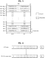
- FIG. 5 illustrates mapping of PUCCH formats to PUCCH regions in UL physical resource blocks.
- a PUCCH is mapped to opposite edges of a UL frequency block.
- the number of available PUCCH RBs may be indicated to UEs in a cell by the PUCCH format 2/2a/2b, through broadcast signaling.
- a BS allocates a PUCCH resource for UCI transmission to a UE in an implicit or explicit manner through higher layer signaling.
- a plurality of PUCCH resource candidates may be set for the UE by a higher layer.
- a PUCCH resource to be used by the UE may be determined in an implicit manner. For example, the UE may receive a PDSCH from the BS and transmit ACK/NACK for a corresponding data unit through a PUCCH resource implicitly determined by a PDCCH resource that carries scheduling information about the PDSCH.
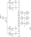
- FIG. 6 illustrates an example of determining PUCCH resources for ACK/NACK.
- a PUCCH resource for ACK/NACK information is not pre-allocated to UEs. Rather, PUCCH resources are used separately by a plurality of UEs within a cell at each time. Specifically, a PUCCH resource that a UE uses to transmit ACK/NACK is implicitly determined based on a PDCCH carrying scheduling information about a PDSCH that delivers the DL data.
- An entire area in which a PDCCH is transmitted in a DL subframe includes a plurality of control channel elements (CCEs) and a PDCCH transmitted to a UE includes one or more CCEs.
- a CCE includes a plurality of (e.g., 9) resource element groups (REGs).
- One REG includes four resource elements (REs) that neighbors each other with an RS excluded.
- the UE transmits ACK/NACK through an implicit PUCCH resource that is derived or calculated according to a function of a specific CCE index (e.g., the first or lowest CCE index) from among the CCE indexes included in a PDCCH received by the UE.
- a specific CCE index e.g., the first or lowest CCE index
- each PUCCH resource index corresponds to a PUCCH resource for ACK/NACK.
- scheduling information about the PDSCH is transmitted to the UE on a PDCCH including CCEs #4, #5 and #6.
- the UE transmits ACK/NACK to a BS on a PUCCH, for example, PUCCH #4 that is derived or calculated from the lowest CCE index 4 constituting the PDCCH.
- FIG. 6 illustrates a case in which up to M' CCEs are present in the DL and up to M PUCCHs are present in UL.
- M may be equal to M', but it is also possible to set M to be different from M' and to map CCEs to PUCCHs in an overlapping manner.
- n PUCCH 1 denotes the index of a PUCCH resource for transmission of ACK/NACK
- N PUCCH 1 denotes a signaling value received from a higher layer
- n CCE may denote the lowest index of the CCE indexes used for transmission of a PDCCH.
- PUCCH formats 1a/1b will be described first below.
- a symbol modulated using BPSK or QPSK is multiplied by a CAZAC sequence having a length of 12.
- Symbols y(0), y(1), y(2), ..., and y(N-1) may be called a block of symbols.
- block-wise-spreading using an orthogonal sequence is applied.
- a Hadamard sequence with a length of 4 is employed for general ACK/NACK information, while a discrete Fourier transform (DFT) with a length of 3 is employed for shortened ACK/NACK information and a reference signal.
- DFT discrete Fourier transform
- a Hadamard sequence with a length of 2 is employed for a reference signal.
- FIG. 7 illustrates an ACK/NACK channel structure for a normal CP.
- FIG. 7 exemplarily shows the structure of a PUCCH channel for transmission of HARQ ACK/NACK without CQI.
- Three consecutive SC-FDMA symbols in the middle of seven SC-FDMA symbols carry RSs and the remaining four SC-FDMA symbols carry ACK/NACK signals.
- two consecutive symbols in the middle of SC-FDMA symbols may carry RSs.
- the number and positions of symbols used for an RS may change depending on a control channel, and the number and positions of symbols used for a ACK/NACK signal associated with the RS may change depending on the number and positions of symbols used for the RS.
- 1-bit ACK/NACK information and 2-bit ACK/NACK information may be represented in a HARQ ACK/NACK modulation symbol using BPSK and QPSK, respectively.
- ACK may be encoded as 1
- NACK may be encoded as 0.
- 2-dimensional spreading is applied to enhance multiplexing capacity. That is, frequency domain spreading and time domain spreading are simultaneously applied to increase the number of UEs or control channels that can be multiplexed.
- a frequency domain sequence is used as a basic sequence.
- a Zadoff-Chu (ZC) sequence one of CAZAC sequences, may be used as the frequency domain sequence.
- ZC Zadoff-Chu
- CSs cyclic shifts
- the number of CS resources supported by SC-FDMA symbols for PUCCH RBs for HARQ ACK/NACK transmission is set by a cell-specific higher-layer signaling parameter ⁇ shif ⁇ t PUCCH , and ⁇ shif ⁇ t PUCCH ⁇ 1 , 2 , 3 represents 12, 6 or 4 shifts.
- a frequency-domain-spread ACK/NACK signal is spread in the time domain using an orthogonal spreading code.
- the orthogonal spreading code a Walsh-Hadamard sequence or a DFT sequence may be used.
- the ACK/NACK signal may be spread using orthogonal sequences (w0, w1, w2, w3) with a length of 4 for four symbols.
- the RS may also be spread using an orthogonal sequence with a length of 3 or 2, which is referred to as orthogonal covering (OC).
- a plurality of UEs may be multiplexed in a code division multiplexing (CDM) scheme using CS resources in the frequency domain and OC resources in the time domain as described above. That is, ACK/NACK information and RSs of a large number of UEs may be multiplexed on the same PUCCH RB.
- CDM code division multiplexing
- the number of supported spreading codes for the ACK/NACK information is restricted by the number of RS symbols. That is, the number of SC-FDMA symbols for RS transmission is smaller than the number of SC-FDMA symbols for ACK/NACK transmission, and therefore multiplexing capacity of an RS is lower than multiplexing capacity of the ACK/NACK information.
- the ACK/NACK information may be transmitted in four symbols, but three orthogonal spreading codes are used rather than four orthogonal spreading codes for the ACK/NACK information. This is because the number of RS transmission symbols is limited to three and thus only three orthogonal spreading codes can be used for the RS.
- Tables 2 and 3 Examples of an orthogonal sequence used in spreading ACK/NACK information are shown in Tables 2 and 3.
- Table 2 shows a sequence for a symbol having a length of 4
- Table 3 shows a sequence for a symbol having a length of 3.
- the sequence for the symbol having a length of 4 is used in PUCCH formats 1/la/lb of a normal subframe configuration.
- the sequence for the symbol with the length of 4 may be applied to the first slot and shortened PUCCH formats 1/1a/1b of the sequence for the symbol with the length of 3 may be applied to the second slot.
- HARQ ACK/NACK signals from 18 different UEs may be multiplexed in a PUCCH RB.
- two symbols are used for RS transmission and four symbols are used for ACK/NACK information transmission in a slot of a subframe of the extended CP if, for example, six CSs in the frequency domain and two OC resources in the time domain are allowed to be used, HARQ ACK/NACK signals from 12 different UEs may be multiplexed in a PUCCH RB.
- a scheduling request is transmitted by requesting scheduling of the UE or not requesting scheduling of the UE.
- An SR channel reuses an ACK/NACK channel structure in PUCCH formats 1a/1b and is configured in an on-off keying (OOK) manner based on the design of the ACK/NACK channel.
- An RS is not transmitted on an SR channel.
- a sequence with a length of 7 is used in the case of the normal CP, and a sequence with a length of 6 is used in the case of the extended CP.
- Different CSs or orthogonal covers may be allocated to an SR and ACK/NACK.
- the UE transmits HARQ ACK/NACK through resources allocated for the SR.
- the UE transmits HARQ ACK/NACK through resources allocated for ACK/NACK.
- PUCCH formats 2/2a/2b are control channels for transmission of channel measurement feedback (CQI, PMI and RI).
- a report period of the channel measurement feedback (hereinafter, referred to as CQI information) and a frequency unit (or frequency resolution) subject to measurement may be controlled by a BS.
- Periodic and aperiodic CQI reports may be supported in the time domain.
- PUCCH format 2 may be used only for the periodic report and a PUSCH may be used for the aperiodic report.
- the BS may instruct the UE to transmit an individual CQI report on a resource scheduled for UL data transmission.
- FIG. 8 illustrates a CQI channel structure for a normal CP.
- SC-FDMA symbols #1 and #5 (second and sixth symbols) from among SC-FDMA symbols #0 to #6 of a slot may be used to transmit a demodulation reference signal (DMRS), and CQI information may be transmitted in the remaining SC-FDMA symbols.
- DMRS demodulation reference signal
- SC-FDMA symbol #3 one SC-FDMA symbol (SC-FDMA symbol #3) is used to transmit the DMRS.
- PUCCH formats 2/2a/2b modulation by a CAZAC sequence is supported, and a symbol modulated according to QPSK is multiplied by a CAZAC sequence with a length of 12.
- the CS of the sequence is changed between symbols and between slots.
- OC is used for the DMRS.
- SC-FDMA symbols Of the seven SC-FDMA symbols included in a slot, two SC-FDMA symbols spaced apart by an interval of three SC-FDMA symbols carry DMRSs and the remaining five SC-FDMA symbols carry CQI information. Two RSs are used in a slot in order to support a high-speed UE.
- a UE is identified using a CS sequence.
- CQI information symbols are modulated into SC-FDMA symbols and transmitted.
- An SC-FDMA symbol includes a sequence. That is, a UE modulates CQI into each sequence and transmits the sequences.
- the number of symbols that can be transmitted in a TTI is 10 and QPSK is determined for modulation of CQI information.
- QPSK mapping is employed for the SC-FDMA symbols
- an SC-FDMA symbol may carry a 2-bit CQI value and thus a slot may carry a 10-bit CQI value. Accordingly, a maximum of a 20-bit CQI value may be carried in a subframe.
- a frequency domain spreading code is used to spread the CQI information in the frequency domain.
- a CAZAC sequence with a length of 12 may be used for the frequency domain spreading code.
- Control channels may be distinguished from each other using CAZAC sequences having different CS values.
- the frequency-domain-spread CQI information is subjected to IFFT.
- 12 different UEs may be orthogonally multiplexed in the same PUCCH RB using 12 equally spaced CSs.
- a DMRS sequence on SC-FDMA symbols #1 and #5 (SC-FDMA symbols #3 for the extended CP) is similar to a CQI signal sequence in the frequency domain, but the DMRS sequence is not modulated as in the case of the CQI information.
- a UE may be semi-statically set by higher layer signaling so as to periodically report different CQI, PMI and RI types on a PUCCH resource indicated by a PUCCH resource index n PUCCH 2 .
- the PUCCH resource index N PUCCH 2 is information indicating a PUCCH region and a CS value used for PUCCH format 2/2a/2b transmission.
- the e-PUCCH format may correspond to PUCCH format 3 in LTE-A.
- Block spreading may be applied to ACK/NACK transmission using PUCCH format 3.
- Block spreading is a method of modulating a control signal using SC-FDMA, which is distinguished from the PUCCH format 1 or 2 series,.
- a symbol sequence may be spread in the time domain using an orthogonal cover code (OCC) and transmitted.
- Control signals of a plurality UEs may be multiplexed in the same RB using the OCC.
- OCC orthogonal cover code
- a symbol sequence is transmitted in the time domain and control signals of multiple UEs are multiplexed using a CS of a CAZAC sequence.
- a symbol sequence is transmitted in the frequency domain and control signals of multiple UEs are multiplexed through the time domain spreading based on an OCC.
- SC-FDMA symbols i.e., data portions
- SF spreading factor
- two RS symbols may be used in one slot.
- the PUCCH channel structure employing the block spreading scheme it may be possible to transmit extended control information compared to the case of existing PUCCH formats 1 and 2.
- content of an ACK/NACK to a plurality of data units may be identified by a combination of an ACK/NACK unit actually used for ACK/NACK transmission and one of QPSK-modulated symbols.
- an ACK/NACK unit carries 2-bit information and receives a maximum of two data units.
- a HARQ ACK/NACK for each of the received data units is represented by an ACK/NACK bit.
- a transmitter that has transmitted data may identify the ACK/NACK results as shown below in Table 4.
- DTX Discontinuous Transmission
- n PUCCH , X 1 denotes an ACK/NACK unit actually used for ACK/NACK transmission.
- the ACK/NACK units may be represented as n PUCCH , 0 1 and n PUCCH , 1 1 .
- b(0), b(1) denote two bits transmitted by selected ACK/NACK units. Modulation symbols transmitted through ACK/NACK units are determined depending on bits of b(0) and b(1).
- the receiver when the receiver successfully receives and decodes two data units (as indicated by ACK, ACK in Table 4), the receiver transmits two bits (1, 1) using the ACK/NACK unit n PUCCH , 1 1 . If the receiver fails to decode (or detect) the first data unit (i.e., data unit 0 corresponding to HARQ-ACK(O)) of the two received data units and successfully decodes the second data unit (i.e. data unit 1 corresponding to HARQ-ACK(1)) (as indicated by NACK/DTX, ACK in Table 4), the receiver transmits two bits (0, 0) using the ACK/NACK unit n PUCCH , 1 1 .
- the first data unit i.e., data unit 0 corresponding to HARQ-ACK(O)
- the receiver transmits two bits (0, 0) using the ACK/NACK unit n PUCCH , 1 1 .
- ACK/NACK information about a plurality of data units using one ACK/NACK unit by linking or mapping a combination of a selected ACK/NACK unit and actual bits of the transmitted ACK/NACK unit (i.e., a combination of selected n PUCCH , 0 1 or n PUCCH , 1 1 and b(0), b(1) in Table 4) to the content of actual ACK/NACK.
- ACK/NACK multiplexing for more than two data units may be readily implemented by extending the principle of the above-described ACK/NACK multiplexing.
- NACK and DTX may not be discriminated from each other when at least one ACK is present for each data unit (that is, NACK and DTX may be coupled as NACK/DTX as shown in Table 4). This is because all ACK/NACK states (i.e., ACK/NACK hypotheses) that may be generated when NACK and DTX are discriminated from each other cannot be represented by only combinations of ACK/NACK units and QPSK-modulated symbols.
- ACK/NACK unit corresponding to a data unit for a definite NACK may be reserved for transmission of a plurality of ACK/NACK signals.
- single carrier transmission with good cubic metric (CM) property or a good peak-to-average power ratio (PAPR), which affects performance of a power amplifier is maintained to effectively utilize the power amplifier of the UE. That is, single carrier characteristics of data to be transmitted may be maintained through DFT-precoding in the case of PUSCH transmission in the legacy LTE system. In the case of PUCCH transmission, single carrier characteristics may be maintained by carrying information on a sequence having single carrier characteristics. However, if DFT-precoded data is non-continuously assigned on a frequency axis, or if PUSCH and PUCCH are simultaneously transmitted, such single carrier characteristics are not maintained.
- CM cubic metric
- PAPR peak-to-average power ratio
- uplink control information (UCI) to be transmitted on a PUCCH may be piggybacked together with data over a PUSCH in order to maintain the single carrier characteristics.
- the legacy LTE UE cannot simultaneously transmit the PUCCH and the PUSCH, and thus the UE multiplexes UCI (CQI/PMI, HARQ-ACK, RI, etc.) in a PUSCH region in a subframe in which the PUSCH is transmitted.
- UCI CQI/PMI, HARQ-ACK, RI, etc.
- UL-SCH data and CQI/PMI may be multiplexed prior to DFT-spreading, such that control information and data are simultaneously transmitted.
- rate matching is performed for the UL-SCH data in consideration of CQI/PMI resources.
- control information such as HARQ ACK and RI may be multiplexed in the PUSCH region by puncturing the UL-SCH data.
- the packets are transmitted over a radio channel, and therefore signal distortion may occur in the transmission process.
- the received distorted signal should be corrected using channel information.
- a signal which is known to both the transmitter and the receiver is transmitted and the degree of distortion of the signal received over the channel is used to detect the channel information. This signal is referred to as a pilot signal or a reference signal.
- a channel state between a transmit antenna and a receive antenna needs to be identified to receive a correct signal. Accordingly, a separate RS is needed for each transmit antenna and, more particularly, for each antenna port.
- the UL RS includes:
- the DL RS includes:
- the RSs may be broadly divided into two reference signals according to the purposes thereof. There are an RS used to acquire channel information and an RS used for data demodulation. Since the former is used when the UE acquires channel information on DL, this RS should be transmitted over a wide band and even a UE which does not receive DL data in a specific sub frame should receive the RS. This RS is also applied to situations such as handover.
- the latter RS is sent by the BS along with a resource on DL.
- the UE may receive the RS to perform channel measurement to implement data modulation. This RS should be transmitted in a region in which data is transmitted.
- the CRS is used for acquisition of channel information and for data demodulation, and the UE-specific RS is used only for data demodulation.
- the CRS is transmitted in every subframe in a wide band and RSs for up to four antenna ports are transmitted according to the number of transmit antennas of the BS.
- CRSs for antenna ports #0 and #1 are transmitted. If the number of transmit antennas of the BS is 4, CRSs for antenna ports #0 to #3 are respectively transmitted.
- FIG. 11 is a diagram illustrating a pattern in which CRSs and DRSs defined in a legacy 3GPP LTE system (e.g., Release-8) are mapped onto resource block (RB) pairs.
- a downlink RB pair as a unit to which an RS is mapped, may be represented as a unit of one subframe in the time domain times 12 subcarriers in the frequency domain. That is, one RB pair has a length of 14 OFDM symbols for a normal CP ( FIG. 11(a) ) and a length of 12 OFDM symbols for an extended CP ( FIG. 11(b) ).
- FIG. 11 shows locations of RSs on RB pairs in a system in which the BS supports four transmit antennas.
- resource elements denoted by “0", “1", “2” and “3” represent the locations of the CRSs for antenna port indexes 0, 1, 2 and 3, respectively.
- REs denoted by “D” represent locations of the DMRSs.
- an enhanced-PDCCH which can be transmitted through the existing PDSCH region is considered as a solution to lack of capacity of a PDCCH due to coordinated multi-point (CoMP), multi user-multiple input multiple output (MU-MIMO), and the like and degradation of PDCCH performance due to inter-cell interference.
- channel estimation may be performed based on DMRSs contrary to the existing CRS-based PDCCH in order to obtain a pre-coding gain.
- EPDCCH transmission may be divided into localized EPDCCH transmission and distributed EPDCCH transmission according to configuration of a physical resource block (PRB) used for EPDCCH transmission.
- the localized EPDCCH transmission represents the case in which enhanced control channel elements (ECCEs) used in transmitting one DCI neighbor each other in the frequency domain, and may employ specific pre-coding to obtain a beamforming gain.
- ECCEs enhanced control channel elements
- localized EPDCCH transmission may be based on consecutive ECCEs the number of which corresponds to an aggregation level.
- the distributed EPDCCH transmission represents the case in which an EPDCCH is transmitted on separated PRB pairs in the frequency domain. Distributed EPDCCH transmission has a benefit in terms of frequency diversity.
- distributed EPDCCH transmission may be based on ECCEs including four EREGs contained in each PRB pair separated in the frequency domain.
- one or two EPDCCH PRB sets may be configured by higher layer signaling, and each EPDCCH PRB set may be intended for one of localized EDPCCH transmission and distributed EPDCCH transmission.
- the UE may perform blind decoding as in a legacy LTE/LTE-A system to receive/acquire DCI over an EPDCCH. More specifically, the UE may attempt to decode (or monitor) a set of EPDCCH candidates at each aggregation level, for DCI formats corresponding to set transmission modes.
- the set of EPDCCH candidates subjected to monitoring may be referred to as a specific search space for the EPDCCH UE, and the search space may be set/configured for each aggregation level.
- the aggregation levels may be ⁇ 1, 2, 4, 8, 16, 32 ⁇ according to a type of a subframe, the length of a CP, and the amount of available resources in a PRB pair, which is more or less different from the case of a legacy LTE/LTE-A system.
- REs included in a PRB pair set are indexed by EREGs, and the EREGs are in turn indexed by ECCEs.
- EPDCCH candidates configuring the search space may be determined based on the indexed ECCEs and then blind decoding may be performed. Thereby, control information may be received.
- EREG corresponds to REG in the legacy LTE/LTE-A
- ECCE corresponds to CCE in the legacy LTE/LTE-A.
- a PRB pair may include 16 EREGs.
- the UE having received an EPDCCH may transmit an ACK/NACK/DTX for the EPDCCH over the PUCCH.
- the index of a resource i.e., a PUCCH resource may be determined by the lowest ECCE index of the ECCE indexes used for transmission of the EPDCCH in a manner similar to Equation 1 discussed above. That is, the index may be expressed as Equation 2 given below.
- n PUCCH ⁇ ECCE 1 n ECCE + N PUCCH 1
- n PUCCH ⁇ ECCE 1 is the index of the PUCCH resource
- n ECCE is the lowest ECCE index of the ECCE indexes used in transmitting the EPDCCH
- N PUCCH 1 (which may be replaced by N PUCCH , EPDCCH 1 ) , which is a value delivered through higher layer signaling, represents the point where the PUCCH resource index starts.
- a PUCCH resource index is determined solely by Equation 2
- resource collision may occur.
- ECCE indexing is independently conducted in each EPDCCH PRB set, and thus the lowest ECCE indexes of the EPDCCH PRB sets may equal each other.
- This problem may be addressed by setting different start points of the PUCCH resources for different users.
- setting the start point of the PUCCH resource differently for every user results in reservation of many PUCCH resources and is thus inefficient.
- DCI of multiple users may be transmitted over the EPDCCH at the same ECCE location as in the case of MU-MIMO, and therefore there is also a need for a method for allocation of PUCCH resources considering the aforementioned case.
- ARO HARQ-ACK Resource Offset
- a BS designates one of the ARO values in Table 5 for a specific UE, and then informs, through a DCI format, the specific UE of an ARO to use in determining a PUCCH resource.
- the UE may detect an ARO field in the DCI format thereof and transmit a reception acknowledgement through a PUCCH resource determined using the detected field value.
- FIG. 11(a) illustrates uplink-downlink configurations used in TDD
- FIG. 11(b) illustrates ACK/NACK for TDD UL-DL configuration 2.
- FIG. 11 in TDD UL-DL configuration 2, subframes usable for UL are limited to subframes #2 and #7.
- DL association set indexes are defined as shown in Table 6 below.
- each number indicates the number of subframes back to a DL subframe from the current UL subframe.
- ACK/NACK for the 8th, 7th, 4th and 6th subframes i.e., subframes 4, 5, 8 and 6 of the previous radio frame
- preceding subframe #2 is transmitted in subframe #2 as shown in FIG. 11(b) .
- a resource allocation scheme in which PUCCH resources are sequentially attached to each other according to the order of the association set for each EPDCCH PRB set is used.
- UL-DL configuration 5 for example, a PUCCH resource region for subframes corresponding to association set ⁇ 13, 12, 9, 8, 7, 5, 4, 11, 6 ⁇ is reserved in subframe 2 for EPDCCH-PRB set j . This example is illustrated in FIG. 12 . Referring to FIG. 12 .
- each block is a PUCCH resource region for each subframe corresponding to an association set
- m is the index of a DL subframe to be transmitted in subframe #2 (i.e., the sequential indexes in association set ⁇ 13, 12, 9, 8, 7, 5, 4, 11, 6 ⁇ .
- N eCCE , i,j is the number of ECCEs of i-th subframe in EPDCCH-PRB-set j .
- reserving all the PUCCH resource regions for multiple DL subframes in a UL subframe as in FIG. 12 may result in waste of the PUCCH resources.
- a set of possible value for the ARO includes an ARO value as in Equation 3 below.
- m denotes an index of two or more subframes (the aforementioned sequential index)
- N eCCE,i,j denotes the number of ECCEs of i-th subframe in EPDCCH-PRB-set j .
- the ARO value according to Equation 3 may move/shift the PUCCH resource of a specific subframe to a PUCCH resource region for a subframe prior to the specific subframe (which may correspond to the ARO region of the specific subframe even after application of ARO depending on the shift amount). Further, the first ARO value performes functions to provide a different shift amount depending on which group the specific subframe belongs to among the groups related to two or more subframes, which will be described in more detail with reference to FIG. 13 .
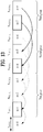
- FIG. 13 is a diagram illustrating stacking of PUCCH resource regions for DL subframes corresponding to an association set in subframe #2 in the case of UL-DL configuration 5 as shown in FIG. 12 .
- Each block is a PUCCH resource region for each subframe corresponding to an association set
- m is the index of a DL subframe to transmit in subframe #2 (i.e., the sequential indexes in association set ⁇ 13, 12, 9, 8, 7, 5, 4, 11, 6 ⁇ )
- N ecCE,i,j is the number of ECCEs of i-th subframe in EPDCCH-PRB-set j .
- the ARO value is -(the number of ECCEs of the last preceding subframe+1).
- the ARO value is -(the number of ECCEs of the last two preceding subframes+1).
- the ARO value is -(the number of ECCEs of the last three preceding subframes+1).
- the first ARO value provides/allocates different shift amounts (i.e., a shift amount by the number of ECCEs of the last preceding subframe+1 for the first group, a shift amount by the number of ECCEs of the last two preceding subframes+1 for the second group, and a shift amount by the number of ECCEs of the last three preceding subframes+1 for the third group) to the groups, when the association set into up to three groups (i.e., a first group of the second subframe to the fourth subframe, a second group of the fifth subframe to the seventh subframe, and a third group of the eighth subframe to the ninth subframe).
- shift amounts i.e., a shift amount by the number of ECCEs of the last preceding subframe+1 for the first group, a shift amount by the number of ECCEs of the last two preceding subframes+1 for the second group, and a shift amount by the number of ECCEs of the last three preceding subframes+1 for the third group
- the ARO set is ⁇ -2,-1,0,2 ⁇ .
- ARO sets according to Embodiment 2 may be given by Equation 4 below.
- a and b have values by which DL subframes in a bundling window are divided into groups.
- PUCCH resources of subframes having m between 1 and a may be shifted to the PUCCH resource region for the first subframe
- PUCCH resources of subframes having m between a and b may be shifted to the PUCCH resource region for the second subframe
- PUCCH resources of subframes having m greater than or equal to b+1 may be shifted to the PUCCH resource region for the third subframe.
- x, y, z, x', y' and z' are integers much less than N eCCE , i,j , and may have predetermined values or signaled values.
- ARO set according to Embodiment 3 may be given by Equation 5 below.
- the first ARO value is for shift of PUCCH resources to the PUCCH resource region for the first subframe
- the second ARO value is for shift of PUCCH resources to the PUCCH resource region for the second subframe.
- ARO sets according to Embodiment 4 may be given by Equation 6 below.
- ARO sets according to Embodiment 5 may be given by Equation 7 below.
- the subframes in the association set are divided into three groups. Maximum shift amounts are provided to the groups such that the first group is shifted up to the PUCCH resource region for the first and second subframes, the second group is shifted up to the PUCCH resource region for the second and third subframes, and the third group is shifted up to the PUCCH resource region for the third and fourth subframes. While the subframes are illustrated as being divided into three groups in the above example, the subframes may be divided into two groups as necessary. In this case, the ARO set of the last group or the second group of the above embodiment may not be used.
- ARO sets according to Embodiment 6 may be given by Equation 8 below.
- the subframes in the association set are divided into up to two groups.
- an ARO value to shift the resources to the PUCCH resource region for the first subframe or an ARO to shift the resources to the PUCCH resource region for a previous subframe may be applied.
- an ARO value to shift the resources to the PUCCH resource region for the second subframe or an ARO value to shift the resources to the PUCCH resource region for a previous subframe may be applied.
- ARO sets according to Embodiment 7 may be given by Equation 9 below.
- the subframes in the association set are divided into up to two groups, and an ARO value to shift PUCCH resources to the PUCCH resource region for the first and second subframes may be applied to the first group.
- An ARO value to shift PUCCH resources to the PUCCH resource region for the third and fourth subframes may be applied to the second group.
- ARO sets according to Embodiment 8 may be given by Equation 10 below.
- ARO sets according to Embodiment 9 may be given by Equation 11 below.
- ARO sets according to Embodiment 10 may be given by Equation 12 below.
- ARO sets according to Embodiment 11 may be given by Equation 13 below.
- ARO sets according to Embodiment 12 may be given by Equation 14 below.
- the subframes in the association set are divided into up to two groups, and ARO having an offset value which is variable depending on the value of m may be used for the second group.
- the subframes in the association set may be divided into some groups and an ARO set applied to the respective groups may be set such that the large offset values are equal to each other, and small offset values of x, y and z are different from each other.
- the ARO set is ⁇ - X-x,-Y-y-Z-z, 0 ⁇ or ⁇ - X - x-Y - y ,0,2 ⁇ , only the small offsets of x, y and z may be set to different values.
- number 11 may come last in order, unlike the example of Table 6. That is, Table 6 is changed to Table 8. In this case, excessive reservation of PUCCH resources may be suppressed.
- the subframe corresponding to number 11 is a special subframe since an EPDCCH is not transmitted in that subframe.
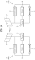
- FIG. 14 is a diagram illustrating configuration of a transmit point apparatus and a UE according to one embodiment of the present invention.
- a transmit point apparatus 10 may include a receive module 11, a transmit module 12, a processor 13, a memory 14, and a plurality of antennas 15.
- the antennas 15 represent the transmit point apparatus that supports MIMO transmission and reception.
- the receive module 11 may receive various signals, data and information from a UE on an uplink.
- the transmit module 12 may transmit various signals, data and information to a UE on a downlink.
- the processor 13 may control overall operation of the transmit point apparatus 10.
- the processor 13 of the transmit point apparatus 10 may perform processes necessary for the embodiments described above.
- the processor 13 of the transmit point apparatus 10 may function to operationally process information received by the transmit point apparatus 10 or information to be transmitted from the transmit point apparatus 10, and the memory 14, which may be replaced with an element such as a buffer (not shown), may store the processed information for a predetermined time.
- a UE 20 may include a receive module 21, a transmit module 22, a processor 23, a memory 24, and a plurality of antennas 25.
- the antennas 25 represent the UE that supports MIMO transmission and reception.
- the receive module 21 may receive various signals, data and information from an eNB on a downlink.
- the transmit module 22 may transmit various signals, data and information to an eNB on an uplink.
- the processor 23 may control overall operation of the UE 20.
- the processor 23 of the UE 20 may perform processes necessary for the embodiments described above.
- the processor 23 of the UE 20 may function to operationally process information received by the UE 20 or information to be transmitted from the UE 20, and the memory 24, which may be replaced with an element such as a buffer (not shown), may store the processed information for a predetermined time.
- the configurations of the transmit point apparatus and the UE as described above may be implemented such that the above-described embodiments can be independently applied or two or more thereof can be simultaneously applied, and description of redundant parts is omitted for clarity.
- Description of the transmit point apparatus 10 in FIG. 14 may be equally applied to a relay as a downlink transmitter or an uplink receiver, and description of the UE 20 may be equally applied to a relay as a downlink receiver or an uplink transmitter.
- the embodiments of the present invention may be implemented through various means, for example, hardware, firmware, software, or a combination thereof.
- a method according to embodiments of the present invention may be embodied as one or more application specific integrated circuits (ASICs), one or more digital signal processors (DSPs), one or more digital signal processing devices (DSPDs), one or more programmable logic devices (PLDs), one or more field programmable gate arrays (FPGAs), a processor, a controller, a microcontroller, a microprocessor, etc.
- ASICs application specific integrated circuits
- DSPs digital signal processors
- DSPDs digital signal processing devices
- PLDs programmable logic devices
- FPGAs field programmable gate arrays
- processor a controller, a microcontroller, a microprocessor, etc.
- a method according to embodiments of the present invention may be embodied as a module, a procedure, or a function that performs the functions or operations described above.
- Software code may be stored in a memory unit and executed by a processor.
- the memory unit is located at the interior or exterior of the processor and may transmit and receive data to and from the processor via various known means.
- Embodiments of the present invention are applicable to various mobile communication systems.
Claims (5)
- Procédé pour transmettre une réponse d'acquittement de réception par un équipement utilisateur (20) dans un système de communication par duplexage à répartition dans le temps, TDD, d'évolution à long terme, LTE, /LTE évolué, LTE-A, comprenant :recevoir un canal de commande de liaison descendante physique amélioré, EPDCCH ;déterminer une ressource de canal de commande de liaison montante physique, PUCCH, sur la base d'un indice d'élément de canal de commande amélioré, ECCE, le plus faible parmi des indices ECCE construisant l'EPDCCH et d'un décalage de ressource HARQ-ACK, ARO ; ettransmettre une réponse d'acquittement de réception par l'intermédiaire de la ressource de PUCCH,caractérisé par le fait quelorsqu'une réponse d'acquittement de réception associée à au moins deux sous-trames de liaison descendante, DL, planifiées par l'EPDCCH est transmise dans une sous-trame pour la transmission de la réponse d'acquittement de réception, un ensemble de valeurs possibles pour l'ARO comprend
 où m est un indice des au moins deux sous-trames DL et le m est égal ou supérieur à 4, et où N eCCE,i,j est le nombre d'ECCE d'une ième sous-trame dans l'ensemble EPDCCH-PRB j.
 - Procédé selon la revendication 1, dans lequel l'ensemble de valeurs possibles pour l'ARO est

- Procédé selon la revendication 1, dans lequel, lorsqu'une réponse d'acquittement de réception associée à une sous-trame est transmise dans une sous-trame pour la transmission de la réponse d'acquittement de réception, l'ensemble de valeurs possibles pour l'ARO est

- Procédé selon la revendication 1, dans lequel l'ARO est indiqué par des informations de commande de liaison descendante, DCI, les DCI étant transmises sur l'EPDCCH.
- Appareil d'équipement utilisateur, UE, (20) pour transmettre une réponse d'acquittement de réception dans un système de communication par duplexage à répartition dans le temps, TDD, d'évolution à long terme, LTE, /LTE évolué, LTE-A, comprenant :un module de réception (21) ; etun processeur (23),le processeur (23) recevant un canal de commande de liaison descendante physique amélioré, EPDCCH, déterminant une ressource de canal de commande de liaison montante physique, PUCCH, sur la base d'un indice d'élément de canal de commande amélioré, ECCE, le plus faible parmi des indices ECCE construisant l'EPDCCH et d'un décalage de ressource HARQ-ACK, ARO, et transmettant une réponse d'acquittement de réception par l'intermédiaire de la ressource de PUCCH,caractérisé par le fait quelorsqu'une réponse d'acquittement de réception associée à au moins deux sous-trames DL planifiées par l'EPDCCH est transmise dans une sous-trame pour la transmission de la réponse d'acquittement de réception, un ensemble de valeurs possibles pour l'ARO comprend
 où m est un indice des au moins deux sous-trames DL et le m est égal ou supérieur à 4, etoù NeCCE,i,j est le nombre d'ECCE d'une ième sous-trame dans l'ensemble EPDCCH-PRB j.
Applications Claiming Priority (3)
| Application Number | Priority Date | Filing Date | Title |
|---|---|---|---|
| US201361758766P | 2013-01-31 | 2013-01-31 | |
| US201361759382P | 2013-01-31 | 2013-01-31 | |
| PCT/KR2014/000884 WO2014119944A1 (fr) | 2013-01-31 | 2014-01-29 | Procédé et appareil permettant de transmettre un accusé de réception dans un système de communication sans fil |
Publications (3)
| Publication Number | Publication Date |
|---|---|
| EP2953287A1 EP2953287A1 (fr) | 2015-12-09 |
| EP2953287A4 EP2953287A4 (fr) | 2016-09-21 |
| EP2953287B1 true EP2953287B1 (fr) | 2019-12-04 |
Family
ID=51262592
Family Applications (1)
| Application Number | Title | Priority Date | Filing Date |
|---|---|---|---|
| EP14745669.3A Active EP2953287B1 (fr) | 2013-01-31 | 2014-01-29 | Procédé et appareil permettant de transmettre un accusé de réception dans un système de communication sans fil |
Country Status (6)
| Country | Link |
|---|---|
| US (3) | US9401795B2 (fr) |
| EP (1) | EP2953287B1 (fr) |
| JP (2) | JP6006881B2 (fr) |
| KR (1) | KR102214071B1 (fr) |
| CN (2) | CN108494531B (fr) |
| WO (1) | WO2014119944A1 (fr) |
Families Citing this family (17)
| Publication number | Priority date | Publication date | Assignee | Title |
|---|---|---|---|---|
| KR20150032857A (ko) * | 2012-06-12 | 2015-03-30 | 엘지전자 주식회사 | 무선 통신 시스템에서 epdcch(enhanced physical downlink channel)를 통한 제어정보 수신 방법 및 장치 |
| CN108494531B (zh) | 2013-01-31 | 2021-07-13 | Lg 电子株式会社 | 在无线通信系统中发送接收肯定应答的方法和装置 |
| EP3107237B1 (fr) * | 2014-02-14 | 2019-06-05 | LG Electronics Inc. | Procédé et appareil de transmission d'accusé de réception harq (harq-ack) dans un système de communication sans fil |
| EP3119024B1 (fr) * | 2014-03-12 | 2021-02-17 | LG Electronics Inc. | Procédé permettant de transmettre un canal de commande en liaison montante dans un système de communication sans fil qui prend en charge un changement d'utilisation de ressources radio, et appareil associé |
| CA3112710C (fr) * | 2014-08-25 | 2024-01-16 | ONE Media, LLC | Configuration dynamique d'un preambule de trame de donnees de transport phy de multiplexage par repartition orthogonale de la frequence souple |
| KR102451527B1 (ko) | 2015-03-09 | 2022-10-06 | 원 미디어, 엘엘씨 | 시스템 발견 및 시그널링 |
| US10554346B2 (en) * | 2015-09-25 | 2020-02-04 | Telefonaktiebolaget Lm Ericsson (Publ) | Allocating space for a plurality of control sets for HARQ |
| US10681708B2 (en) * | 2016-12-16 | 2020-06-09 | Qualcomm Incorporated | Subslot bundling and acknowledgement |
| WO2018170930A1 (fr) * | 2017-03-24 | 2018-09-27 | 华为技术有限公司 | Procédé et dispositif de transmission d'informations de commande de liaison montante |
| CN108809524B (zh) * | 2017-04-28 | 2021-04-09 | 华为技术有限公司 | 传输反馈信息的方法和装置 |
| WO2019026514A1 (fr) | 2017-08-01 | 2019-02-07 | 日本電気株式会社 | Station de base, dispositif terminal, premier dispositif terminal, procédé, programme, support d'enregistrement et système |
| US10644765B2 (en) * | 2017-10-24 | 2020-05-05 | Intel Corporation | Enhanced acknowledgment and power saving for wireless communications |
| CN109802772B (zh) * | 2017-11-17 | 2020-12-08 | 华为技术有限公司 | 一种信息发送的方法及设备 |
| WO2020208679A1 (fr) * | 2019-04-08 | 2020-10-15 | 株式会社Nttドコモ | Terminal utilisateur et procédé de communication sans fil |
| CN112583543B (zh) * | 2019-09-27 | 2022-08-02 | 维沃移动通信有限公司 | 资源确定方法及通信设备 |
| US11261692B2 (en) | 2020-04-15 | 2022-03-01 | Saudi Arabian Oil Company | Method and apparatus for identifying and remediating loss circulation zone |
| US11956171B2 (en) * | 2021-12-08 | 2024-04-09 | Qualcomm Incorporated | Cyclic shift reporting for a reference signal |
Family Cites Families (23)
| Publication number | Priority date | Publication date | Assignee | Title |
|---|---|---|---|---|
| CN1237746C (zh) * | 1998-08-18 | 2006-01-18 | 束达网络公司 | 多层载波离散多音通信技术 |
| JP5283423B2 (ja) * | 2008-05-02 | 2013-09-04 | 株式会社エヌ・ティ・ティ・ドコモ | 移動通信システムにおける基地局装置、ユーザ装置及び方法 |
| US8767632B2 (en) * | 2009-02-05 | 2014-07-01 | Motorola Mobility Llc | Method for uplink acknowledgement/non-acknowledgement messages in a wireless communication system |
| KR20110055367A (ko) * | 2009-11-17 | 2011-05-25 | 엘지전자 주식회사 | 다중 안테나 시스템에서 harq 수행 방법 및 장치 |
| CN101795492B (zh) * | 2010-01-15 | 2015-01-28 | 中兴通讯股份有限公司 | 一种多载波系统中物理上行控制信道资源的确定方法 |
| US20110235599A1 (en) * | 2010-03-29 | 2011-09-29 | Samsung Electronics Co., Ltd. | Method and system for uplink acknowledgement signaling in carrier-aggregated wireless communication systems |
| CN102378373A (zh) * | 2010-08-17 | 2012-03-14 | 电信科学技术研究院 | 一种控制信道传输和资源确定方法、基站及终端 |
| CN103797736B (zh) * | 2011-06-07 | 2017-06-23 | 韩国电子通信研究院 | 移动通信系统的传送和接收控制信息的方法 |
| CN102223215B (zh) * | 2011-06-23 | 2016-09-21 | 电信科学技术研究院 | Ack/nack的传输方法、接收方法及其装置 |
| US9265017B2 (en) * | 2012-02-07 | 2016-02-16 | Telefonaktiebolaget L M Ericsson | Reference signals in wireless communication |
| US9526091B2 (en) * | 2012-03-16 | 2016-12-20 | Intel Corporation | Method and apparatus for coordination of self-optimization functions in a wireless network |
| CN103327614B (zh) * | 2012-03-19 | 2016-08-03 | 上海贝尔股份有限公司 | 将用于ACK/NACK的扩展的PUCCH资源与ePDCCH所使用的eCCE隐式关联的方法 |
| US9198181B2 (en) * | 2012-03-19 | 2015-11-24 | Blackberry Limited | Enhanced common downlink control channels |
| WO2014025140A1 (fr) * | 2012-08-06 | 2014-02-13 | Kt Corporation | Transmission d'informations de commande et mappage de ressource de canal de commande de liaison montante |
| CN104798429B (zh) * | 2012-09-27 | 2018-09-21 | 瑞典爱立信有限公司 | 对于增强物理下行链路控制信道的tdd pucch harq资源分配的方法和系统 |
| EP2912796B1 (fr) * | 2012-10-26 | 2023-03-29 | Apple Inc. | Attribution de ressources (ra) de canal de commande de liaison montante physique (pucch) pour une transmission d'accusé de réception de demande de retransmission automatique hybride (harq-ack). |
| US11245507B2 (en) * | 2012-11-02 | 2022-02-08 | Texas Instruments Incorporated | Efficient allocation of uplink HARQ-ACK resources for LTE enhanced control channel |
| US9407302B2 (en) * | 2012-12-03 | 2016-08-02 | Intel Corporation | Communication device, mobile terminal, method for requesting information and method for providing information |
| CN103874096B (zh) * | 2012-12-18 | 2017-12-26 | 中兴通讯股份有限公司 | 一种下行控制信息的发送和检测方法、发送端和接收端 |
| US9271242B2 (en) | 2013-01-14 | 2016-02-23 | Intel IP Corporation | Energy-harvesting devices in wireless networks |
| CN108494531B (zh) | 2013-01-31 | 2021-07-13 | Lg 电子株式会社 | 在无线通信系统中发送接收肯定应答的方法和装置 |
| US9160515B2 (en) * | 2013-04-04 | 2015-10-13 | Intel IP Corporation | User equipment and methods for handover enhancement using scaled time-to-trigger and time-of-stay |
| US9667386B2 (en) * | 2013-11-13 | 2017-05-30 | Samsung Electronics Co., Ltd | Transmission of control channel and data channels for coverage enhancements |
-
2014
- 2014-01-29 CN CN201810153565.1A patent/CN108494531B/zh active Active
- 2014-01-29 WO PCT/KR2014/000884 patent/WO2014119944A1/fr active Application Filing
- 2014-01-29 EP EP14745669.3A patent/EP2953287B1/fr active Active
- 2014-01-29 JP JP2015534404A patent/JP6006881B2/ja active Active
- 2014-01-29 US US14/431,024 patent/US9401795B2/en active Active
- 2014-01-29 CN CN201480002761.9A patent/CN104737484B/zh active Active
- 2014-01-29 KR KR1020157023648A patent/KR102214071B1/ko active IP Right Grant
-
2015
- 2015-04-06 US US14/679,692 patent/US9608790B2/en active Active
-
2016
- 2016-09-09 JP JP2016176207A patent/JP6272969B2/ja active Active
-
2017
- 2017-02-02 US US15/423,506 patent/US9900870B2/en active Active
Non-Patent Citations (1)
| Title |
|---|
| None * |
Also Published As
| Publication number | Publication date |
|---|---|
| CN104737484B (zh) | 2018-03-23 |
| KR20150140637A (ko) | 2015-12-16 |
| JP6006881B2 (ja) | 2016-10-12 |
| EP2953287A1 (fr) | 2015-12-09 |
| US9900870B2 (en) | 2018-02-20 |
| WO2014119944A1 (fr) | 2014-08-07 |
| CN104737484A (zh) | 2015-06-24 |
| JP2017011751A (ja) | 2017-01-12 |
| CN108494531B (zh) | 2021-07-13 |
| JP6272969B2 (ja) | 2018-01-31 |
| US20170150495A1 (en) | 2017-05-25 |
| KR102214071B1 (ko) | 2021-02-09 |
| US9401795B2 (en) | 2016-07-26 |
| EP2953287A4 (fr) | 2016-09-21 |
| US20150215081A1 (en) | 2015-07-30 |
| US9608790B2 (en) | 2017-03-28 |
| US20160020884A1 (en) | 2016-01-21 |
| CN108494531A (zh) | 2018-09-04 |
| JP2015536089A (ja) | 2015-12-17 |
Similar Documents
| Publication | Publication Date | Title |
|---|---|---|
| US9900870B2 (en) | Method and apparatus for transmitting receipt acknowledgement in wireless communication system | |
| US10581562B2 (en) | Method and apparatus for transmitting HARQ-ACK in wireless communication system | |
| EP2908446B1 (fr) | Méthode et appareil de transmission d'accusé de réception dans un système de communication sans fil | |
| US9717089B2 (en) | Method and apparatus for transmitting acknowledgement of reception in wireless communication system | |
| EP2830244B1 (fr) | Procédé et appareil de réception d'informations de commande dans un système de communication sans fil | |
| EP2945310B1 (fr) | Procédé et appareil pour la réponse de confirmation de réception dans un système de communications sans fil | |
| US20180255542A1 (en) | Method and apparatus for transmitting and receiving uplink in wireless communication system | |
| US9660787B2 (en) | Method and apparatus for transmitting reception acknowledgement in wireless communication system | |
| US9848441B2 (en) | Method and apparatus for receiving downlink control information through an enhanced physical downlink control channel in wireless communication | |
| US9750005B2 (en) | Method and apparatus for transmitting control information in wireless communication system | |
| US9768926B2 (en) | Method and apparatus for receiving control information in wireless communication system |
Legal Events
| Date | Code | Title | Description |
|---|---|---|---|
| PUAI | Public reference made under article 153(3) epc to a published international application that has entered the european phase |
Free format text: ORIGINAL CODE: 0009012 |
|
| 17P | Request for examination filed |
Effective date: 20150302 |
|
| AK | Designated contracting states |
Kind code of ref document: A1 Designated state(s): AL AT BE BG CH CY CZ DE DK EE ES FI FR GB GR HR HU IE IS IT LI LT LU LV MC MK MT NL NO PL PT RO RS SE SI SK SM TR |
|
| AX | Request for extension of the european patent |
Extension state: BA ME |
|
| DAX | Request for extension of the european patent (deleted) | ||
| A4 | Supplementary search report drawn up and despatched |
Effective date: 20160819 |
|
| RIC1 | Information provided on ipc code assigned before grant |
Ipc: H04L 1/16 20060101AFI20160815BHEP Ipc: H04W 72/04 20090101ALI20160815BHEP Ipc: H04L 5/00 20060101ALI20160815BHEP Ipc: H04L 1/18 20060101ALI20160815BHEP |
|
| STAA | Information on the status of an ep patent application or granted ep patent |
Free format text: STATUS: EXAMINATION IS IN PROGRESS |
|
| 17Q | First examination report despatched |
Effective date: 20190104 |
|
| GRAP | Despatch of communication of intention to grant a patent |
Free format text: ORIGINAL CODE: EPIDOSNIGR1 |
|
| STAA | Information on the status of an ep patent application or granted ep patent |
Free format text: STATUS: GRANT OF PATENT IS INTENDED |
|
| INTG | Intention to grant announced |
Effective date: 20190626 |
|
| GRAS | Grant fee paid |
Free format text: ORIGINAL CODE: EPIDOSNIGR3 |
|
| GRAA | (expected) grant |
Free format text: ORIGINAL CODE: 0009210 |
|
| STAA | Information on the status of an ep patent application or granted ep patent |
Free format text: STATUS: THE PATENT HAS BEEN GRANTED |
|
| AK | Designated contracting states |
Kind code of ref document: B1 Designated state(s): AL AT BE BG CH CY CZ DE DK EE ES FI FR GB GR HR HU IE IS IT LI LT LU LV MC MK MT NL NO PL PT RO RS SE SI SK SM TR |
|
| REG | Reference to a national code |
Ref country code: GB Ref legal event code: FG4D |
|
| REG | Reference to a national code |
Ref country code: CH Ref legal event code: EP |
|
| REG | Reference to a national code |
Ref country code: AT Ref legal event code: REF Ref document number: 1210788 Country of ref document: AT Kind code of ref document: T Effective date: 20191215 |
|
| REG | Reference to a national code |
Ref country code: DE Ref legal event code: R096 Ref document number: 602014057807 Country of ref document: DE |
|
| REG | Reference to a national code |
Ref country code: IE Ref legal event code: FG4D |
|
| REG | Reference to a national code |
Ref country code: SE Ref legal event code: TRGR |
|
| REG | Reference to a national code |
Ref country code: LT Ref legal event code: MG4D |
|
| PG25 | Lapsed in a contracting state [announced via postgrant information from national office to epo] |
Ref country code: GR Free format text: LAPSE BECAUSE OF FAILURE TO SUBMIT A TRANSLATION OF THE DESCRIPTION OR TO PAY THE FEE WITHIN THE PRESCRIBED TIME-LIMIT Effective date: 20200305 Ref country code: NO Free format text: LAPSE BECAUSE OF FAILURE TO SUBMIT A TRANSLATION OF THE DESCRIPTION OR TO PAY THE FEE WITHIN THE PRESCRIBED TIME-LIMIT Effective date: 20200304 Ref country code: BG Free format text: LAPSE BECAUSE OF FAILURE TO SUBMIT A TRANSLATION OF THE DESCRIPTION OR TO PAY THE FEE WITHIN THE PRESCRIBED TIME-LIMIT Effective date: 20200304 Ref country code: LT Free format text: LAPSE BECAUSE OF FAILURE TO SUBMIT A TRANSLATION OF THE DESCRIPTION OR TO PAY THE FEE WITHIN THE PRESCRIBED TIME-LIMIT Effective date: 20191204 Ref country code: LV Free format text: LAPSE BECAUSE OF FAILURE TO SUBMIT A TRANSLATION OF THE DESCRIPTION OR TO PAY THE FEE WITHIN THE PRESCRIBED TIME-LIMIT Effective date: 20191204 Ref country code: FI Free format text: LAPSE BECAUSE OF FAILURE TO SUBMIT A TRANSLATION OF THE DESCRIPTION OR TO PAY THE FEE WITHIN THE PRESCRIBED TIME-LIMIT Effective date: 20191204 |
|
| REG | Reference to a national code |
Ref country code: NL Ref legal event code: FP |
|
| PG25 | Lapsed in a contracting state [announced via postgrant information from national office to epo] |
Ref country code: HR Free format text: LAPSE BECAUSE OF FAILURE TO SUBMIT A TRANSLATION OF THE DESCRIPTION OR TO PAY THE FEE WITHIN THE PRESCRIBED TIME-LIMIT Effective date: 20191204 Ref country code: RS Free format text: LAPSE BECAUSE OF FAILURE TO SUBMIT A TRANSLATION OF THE DESCRIPTION OR TO PAY THE FEE WITHIN THE PRESCRIBED TIME-LIMIT Effective date: 20191204 |
|
| PG25 | Lapsed in a contracting state [announced via postgrant information from national office to epo] |
Ref country code: AL Free format text: LAPSE BECAUSE OF FAILURE TO SUBMIT A TRANSLATION OF THE DESCRIPTION OR TO PAY THE FEE WITHIN THE PRESCRIBED TIME-LIMIT Effective date: 20191204 |
|
| PG25 | Lapsed in a contracting state [announced via postgrant information from national office to epo] |
Ref country code: PT Free format text: LAPSE BECAUSE OF FAILURE TO SUBMIT A TRANSLATION OF THE DESCRIPTION OR TO PAY THE FEE WITHIN THE PRESCRIBED TIME-LIMIT Effective date: 20200429 Ref country code: ES Free format text: LAPSE BECAUSE OF FAILURE TO SUBMIT A TRANSLATION OF THE DESCRIPTION OR TO PAY THE FEE WITHIN THE PRESCRIBED TIME-LIMIT Effective date: 20191204 Ref country code: CZ Free format text: LAPSE BECAUSE OF FAILURE TO SUBMIT A TRANSLATION OF THE DESCRIPTION OR TO PAY THE FEE WITHIN THE PRESCRIBED TIME-LIMIT Effective date: 20191204 Ref country code: RO Free format text: LAPSE BECAUSE OF FAILURE TO SUBMIT A TRANSLATION OF THE DESCRIPTION OR TO PAY THE FEE WITHIN THE PRESCRIBED TIME-LIMIT Effective date: 20191204 Ref country code: EE Free format text: LAPSE BECAUSE OF FAILURE TO SUBMIT A TRANSLATION OF THE DESCRIPTION OR TO PAY THE FEE WITHIN THE PRESCRIBED TIME-LIMIT Effective date: 20191204 |
|
| PG25 | Lapsed in a contracting state [announced via postgrant information from national office to epo] |
Ref country code: SM Free format text: LAPSE BECAUSE OF FAILURE TO SUBMIT A TRANSLATION OF THE DESCRIPTION OR TO PAY THE FEE WITHIN THE PRESCRIBED TIME-LIMIT Effective date: 20191204 Ref country code: IS Free format text: LAPSE BECAUSE OF FAILURE TO SUBMIT A TRANSLATION OF THE DESCRIPTION OR TO PAY THE FEE WITHIN THE PRESCRIBED TIME-LIMIT Effective date: 20200404 Ref country code: SK Free format text: LAPSE BECAUSE OF FAILURE TO SUBMIT A TRANSLATION OF THE DESCRIPTION OR TO PAY THE FEE WITHIN THE PRESCRIBED TIME-LIMIT Effective date: 20191204 |
|
| REG | Reference to a national code |
Ref country code: CH Ref legal event code: PL |
|
| REG | Reference to a national code |
Ref country code: DE Ref legal event code: R097 Ref document number: 602014057807 Country of ref document: DE |
|
| REG | Reference to a national code |
Ref country code: AT Ref legal event code: MK05 Ref document number: 1210788 Country of ref document: AT Kind code of ref document: T Effective date: 20191204 |
|
| PG25 | Lapsed in a contracting state [announced via postgrant information from national office to epo] |
Ref country code: MC Free format text: LAPSE BECAUSE OF FAILURE TO SUBMIT A TRANSLATION OF THE DESCRIPTION OR TO PAY THE FEE WITHIN THE PRESCRIBED TIME-LIMIT Effective date: 20191204 |
|
| PLBE | No opposition filed within time limit |
Free format text: ORIGINAL CODE: 0009261 |
|
| STAA | Information on the status of an ep patent application or granted ep patent |
Free format text: STATUS: NO OPPOSITION FILED WITHIN TIME LIMIT |
|
| REG | Reference to a national code |
Ref country code: BE Ref legal event code: MM Effective date: 20200131 |
|
| PG25 | Lapsed in a contracting state [announced via postgrant information from national office to epo] |
Ref country code: LU Free format text: LAPSE BECAUSE OF NON-PAYMENT OF DUE FEES Effective date: 20200129 Ref country code: DK Free format text: LAPSE BECAUSE OF FAILURE TO SUBMIT A TRANSLATION OF THE DESCRIPTION OR TO PAY THE FEE WITHIN THE PRESCRIBED TIME-LIMIT Effective date: 20191204 |
|
| 26N | No opposition filed |
Effective date: 20200907 |
|
| PG25 | Lapsed in a contracting state [announced via postgrant information from national office to epo] |
Ref country code: LI Free format text: LAPSE BECAUSE OF NON-PAYMENT OF DUE FEES Effective date: 20200131 Ref country code: AT Free format text: LAPSE BECAUSE OF FAILURE TO SUBMIT A TRANSLATION OF THE DESCRIPTION OR TO PAY THE FEE WITHIN THE PRESCRIBED TIME-LIMIT Effective date: 20191204 Ref country code: CH Free format text: LAPSE BECAUSE OF NON-PAYMENT OF DUE FEES Effective date: 20200131 Ref country code: SI Free format text: LAPSE BECAUSE OF FAILURE TO SUBMIT A TRANSLATION OF THE DESCRIPTION OR TO PAY THE FEE WITHIN THE PRESCRIBED TIME-LIMIT Effective date: 20191204 Ref country code: BE Free format text: LAPSE BECAUSE OF NON-PAYMENT OF DUE FEES Effective date: 20200131 Ref country code: PL Free format text: LAPSE BECAUSE OF FAILURE TO SUBMIT A TRANSLATION OF THE DESCRIPTION OR TO PAY THE FEE WITHIN THE PRESCRIBED TIME-LIMIT Effective date: 20191204 |
|
| PG25 | Lapsed in a contracting state [announced via postgrant information from national office to epo] |
Ref country code: IT Free format text: LAPSE BECAUSE OF FAILURE TO SUBMIT A TRANSLATION OF THE DESCRIPTION OR TO PAY THE FEE WITHIN THE PRESCRIBED TIME-LIMIT Effective date: 20191204 Ref country code: IE Free format text: LAPSE BECAUSE OF NON-PAYMENT OF DUE FEES Effective date: 20200129 |
|
| PG25 | Lapsed in a contracting state [announced via postgrant information from national office to epo] |
Ref country code: TR Free format text: LAPSE BECAUSE OF FAILURE TO SUBMIT A TRANSLATION OF THE DESCRIPTION OR TO PAY THE FEE WITHIN THE PRESCRIBED TIME-LIMIT Effective date: 20191204 Ref country code: MT Free format text: LAPSE BECAUSE OF FAILURE TO SUBMIT A TRANSLATION OF THE DESCRIPTION OR TO PAY THE FEE WITHIN THE PRESCRIBED TIME-LIMIT Effective date: 20191204 Ref country code: CY Free format text: LAPSE BECAUSE OF FAILURE TO SUBMIT A TRANSLATION OF THE DESCRIPTION OR TO PAY THE FEE WITHIN THE PRESCRIBED TIME-LIMIT Effective date: 20191204 |
|
| PG25 | Lapsed in a contracting state [announced via postgrant information from national office to epo] |
Ref country code: MK Free format text: LAPSE BECAUSE OF FAILURE TO SUBMIT A TRANSLATION OF THE DESCRIPTION OR TO PAY THE FEE WITHIN THE PRESCRIBED TIME-LIMIT Effective date: 20191204 |
|
| PGFP | Annual fee paid to national office [announced via postgrant information from national office to epo] |
Ref country code: DE Payment date: 20221205 Year of fee payment: 10 |
|
| P01 | Opt-out of the competence of the unified patent court (upc) registered |
Effective date: 20230524 |
|
| PGFP | Annual fee paid to national office [announced via postgrant information from national office to epo] |
Ref country code: GB Payment date: 20231207 Year of fee payment: 11 |
|
| PGFP | Annual fee paid to national office [announced via postgrant information from national office to epo] |
Ref country code: SE Payment date: 20231206 Year of fee payment: 11 Ref country code: NL Payment date: 20231206 Year of fee payment: 11 Ref country code: FR Payment date: 20231206 Year of fee payment: 11 |