EP2952923B1 - Power conversion device for fuel cell and method for controlling same - Google Patents
Power conversion device for fuel cell and method for controlling same Download PDFInfo
- Publication number
- EP2952923B1 EP2952923B1 EP14862007.3A EP14862007A EP2952923B1 EP 2952923 B1 EP2952923 B1 EP 2952923B1 EP 14862007 A EP14862007 A EP 14862007A EP 2952923 B1 EP2952923 B1 EP 2952923B1
- Authority
- EP
- European Patent Office
- Prior art keywords
- fuel cell
- load
- parameter
- voltage
- converter
- Prior art date
- Legal status (The legal status is an assumption and is not a legal conclusion. Google has not performed a legal analysis and makes no representation as to the accuracy of the status listed.)
- Active
Links
- 239000000446 fuel Substances 0.000 title claims description 132
- 238000000034 method Methods 0.000 title claims description 24
- 238000006243 chemical reaction Methods 0.000 title description 3
- 238000003745 diagnosis Methods 0.000 claims description 30
- 238000004146 energy storage Methods 0.000 claims description 30
- 230000002457 bidirectional effect Effects 0.000 claims description 22
- 230000004044 response Effects 0.000 claims description 21
- 238000001453 impedance spectrum Methods 0.000 claims description 13
- 238000007599 discharging Methods 0.000 claims description 8
- 230000001052 transient effect Effects 0.000 claims description 4
- 238000012545 processing Methods 0.000 claims description 2
- 238000010586 diagram Methods 0.000 description 5
- 238000000157 electrochemical-induced impedance spectroscopy Methods 0.000 description 4
- 238000005516 engineering process Methods 0.000 description 4
- 230000006870 function Effects 0.000 description 4
- QVGXLLKOCUKJST-UHFFFAOYSA-N atomic oxygen Chemical compound [O] QVGXLLKOCUKJST-UHFFFAOYSA-N 0.000 description 3
- 239000003990 capacitor Substances 0.000 description 3
- 239000001257 hydrogen Substances 0.000 description 3
- 229910052739 hydrogen Inorganic materials 0.000 description 3
- 239000001301 oxygen Substances 0.000 description 3
- 229910052760 oxygen Inorganic materials 0.000 description 3
- UFHFLCQGNIYNRP-UHFFFAOYSA-N Hydrogen Chemical compound [H][H] UFHFLCQGNIYNRP-UHFFFAOYSA-N 0.000 description 2
- 230000032683 aging Effects 0.000 description 2
- 230000003247 decreasing effect Effects 0.000 description 2
- 238000003487 electrochemical reaction Methods 0.000 description 2
- 239000000463 material Substances 0.000 description 2
- 238000005259 measurement Methods 0.000 description 2
- XLYOFNOQVPJJNP-UHFFFAOYSA-N water Substances O XLYOFNOQVPJJNP-UHFFFAOYSA-N 0.000 description 2
- 230000001419 dependent effect Effects 0.000 description 1
- 238000005868 electrolysis reaction Methods 0.000 description 1
- 238000011156 evaluation Methods 0.000 description 1
- 238000001914 filtration Methods 0.000 description 1
- 150000002431 hydrogen Chemical class 0.000 description 1
- 230000000737 periodic effect Effects 0.000 description 1
- 230000001603 reducing effect Effects 0.000 description 1
- 230000005236 sound signal Effects 0.000 description 1
- 239000000126 substance Substances 0.000 description 1
- 238000012360 testing method Methods 0.000 description 1
Images


Classifications
-
- G—PHYSICS
- G01—MEASURING; TESTING
- G01R—MEASURING ELECTRIC VARIABLES; MEASURING MAGNETIC VARIABLES
- G01R31/00—Arrangements for testing electric properties; Arrangements for locating electric faults; Arrangements for electrical testing characterised by what is being tested not provided for elsewhere
- G01R31/36—Arrangements for testing, measuring or monitoring the electrical condition of accumulators or electric batteries, e.g. capacity or state of charge [SoC]
-
- G—PHYSICS
- G05—CONTROLLING; REGULATING
- G05F—SYSTEMS FOR REGULATING ELECTRIC OR MAGNETIC VARIABLES
- G05F3/00—Non-retroactive systems for regulating electric variables by using an uncontrolled element, or an uncontrolled combination of elements, such element or such combination having self-regulating properties
- G05F3/02—Regulating voltage or current
- G05F3/08—Regulating voltage or current wherein the variable is dc
- G05F3/10—Regulating voltage or current wherein the variable is dc using uncontrolled devices with non-linear characteristics
- G05F3/16—Regulating voltage or current wherein the variable is dc using uncontrolled devices with non-linear characteristics being semiconductor devices
- G05F3/20—Regulating voltage or current wherein the variable is dc using uncontrolled devices with non-linear characteristics being semiconductor devices using diode- transistor combinations
- G05F3/24—Regulating voltage or current wherein the variable is dc using uncontrolled devices with non-linear characteristics being semiconductor devices using diode- transistor combinations wherein the transistors are of the field-effect type only
-
- G—PHYSICS
- G01—MEASURING; TESTING
- G01R—MEASURING ELECTRIC VARIABLES; MEASURING MAGNETIC VARIABLES
- G01R31/00—Arrangements for testing electric properties; Arrangements for locating electric faults; Arrangements for electrical testing characterised by what is being tested not provided for elsewhere
- G01R31/36—Arrangements for testing, measuring or monitoring the electrical condition of accumulators or electric batteries, e.g. capacity or state of charge [SoC]
- G01R31/3644—Constructional arrangements
- G01R31/3648—Constructional arrangements comprising digital calculation means, e.g. for performing an algorithm
-
- G—PHYSICS
- G01—MEASURING; TESTING
- G01R—MEASURING ELECTRIC VARIABLES; MEASURING MAGNETIC VARIABLES
- G01R31/00—Arrangements for testing electric properties; Arrangements for locating electric faults; Arrangements for electrical testing characterised by what is being tested not provided for elsewhere
- G01R31/36—Arrangements for testing, measuring or monitoring the electrical condition of accumulators or electric batteries, e.g. capacity or state of charge [SoC]
- G01R31/385—Arrangements for measuring battery or accumulator variables
- G01R31/386—Arrangements for measuring battery or accumulator variables using test-loads
-
- H—ELECTRICITY
- H01—ELECTRIC ELEMENTS
- H01M—PROCESSES OR MEANS, e.g. BATTERIES, FOR THE DIRECT CONVERSION OF CHEMICAL ENERGY INTO ELECTRICAL ENERGY
- H01M8/00—Fuel cells; Manufacture thereof
- H01M8/04—Auxiliary arrangements, e.g. for control of pressure or for circulation of fluids
- H01M8/04298—Processes for controlling fuel cells or fuel cell systems
- H01M8/04313—Processes for controlling fuel cells or fuel cell systems characterised by the detection or assessment of variables; characterised by the detection or assessment of failure or abnormal function
- H01M8/04537—Electric variables
- H01M8/04634—Other electric variables, e.g. resistance or impedance
- H01M8/04649—Other electric variables, e.g. resistance or impedance of fuel cell stacks
-
- H—ELECTRICITY
- H01—ELECTRIC ELEMENTS
- H01M—PROCESSES OR MEANS, e.g. BATTERIES, FOR THE DIRECT CONVERSION OF CHEMICAL ENERGY INTO ELECTRICAL ENERGY
- H01M8/00—Fuel cells; Manufacture thereof
- H01M8/04—Auxiliary arrangements, e.g. for control of pressure or for circulation of fluids
- H01M8/04298—Processes for controlling fuel cells or fuel cell systems
- H01M8/04694—Processes for controlling fuel cells or fuel cell systems characterised by variables to be controlled
- H01M8/04858—Electric variables
- H01M8/04865—Voltage
-
- H—ELECTRICITY
- H01—ELECTRIC ELEMENTS
- H01M—PROCESSES OR MEANS, e.g. BATTERIES, FOR THE DIRECT CONVERSION OF CHEMICAL ENERGY INTO ELECTRICAL ENERGY
- H01M8/00—Fuel cells; Manufacture thereof
- H01M8/04—Auxiliary arrangements, e.g. for control of pressure or for circulation of fluids
- H01M8/04298—Processes for controlling fuel cells or fuel cell systems
- H01M8/04694—Processes for controlling fuel cells or fuel cell systems characterised by variables to be controlled
- H01M8/04858—Electric variables
- H01M8/04925—Power, energy, capacity or load
- H01M8/0494—Power, energy, capacity or load of fuel cell stacks
-
- H—ELECTRICITY
- H02—GENERATION; CONVERSION OR DISTRIBUTION OF ELECTRIC POWER
- H02J—CIRCUIT ARRANGEMENTS OR SYSTEMS FOR SUPPLYING OR DISTRIBUTING ELECTRIC POWER; SYSTEMS FOR STORING ELECTRIC ENERGY
- H02J7/00—Circuit arrangements for charging or depolarising batteries or for supplying loads from batteries
- H02J7/0068—Battery or charger load switching, e.g. concurrent charging and load supply
-
- G—PHYSICS
- G01—MEASURING; TESTING
- G01R—MEASURING ELECTRIC VARIABLES; MEASURING MAGNETIC VARIABLES
- G01R31/00—Arrangements for testing electric properties; Arrangements for locating electric faults; Arrangements for electrical testing characterised by what is being tested not provided for elsewhere
- G01R31/36—Arrangements for testing, measuring or monitoring the electrical condition of accumulators or electric batteries, e.g. capacity or state of charge [SoC]
- G01R31/389—Measuring internal impedance, internal conductance or related variables
-
- G—PHYSICS
- G01—MEASURING; TESTING
- G01R—MEASURING ELECTRIC VARIABLES; MEASURING MAGNETIC VARIABLES
- G01R31/00—Arrangements for testing electric properties; Arrangements for locating electric faults; Arrangements for electrical testing characterised by what is being tested not provided for elsewhere
- G01R31/36—Arrangements for testing, measuring or monitoring the electrical condition of accumulators or electric batteries, e.g. capacity or state of charge [SoC]
- G01R31/392—Determining battery ageing or deterioration, e.g. state of health
-
- Y—GENERAL TAGGING OF NEW TECHNOLOGICAL DEVELOPMENTS; GENERAL TAGGING OF CROSS-SECTIONAL TECHNOLOGIES SPANNING OVER SEVERAL SECTIONS OF THE IPC; TECHNICAL SUBJECTS COVERED BY FORMER USPC CROSS-REFERENCE ART COLLECTIONS [XRACs] AND DIGESTS
- Y02—TECHNOLOGIES OR APPLICATIONS FOR MITIGATION OR ADAPTATION AGAINST CLIMATE CHANGE
- Y02E—REDUCTION OF GREENHOUSE GAS [GHG] EMISSIONS, RELATED TO ENERGY GENERATION, TRANSMISSION OR DISTRIBUTION
- Y02E60/00—Enabling technologies; Technologies with a potential or indirect contribution to GHG emissions mitigation
- Y02E60/30—Hydrogen technology
- Y02E60/50—Fuel cells
Definitions
- the following description relates to a power converter for a fuel cell which can perform a diagnosis and a load leveling of the fuel cell, and a method of controlling the same.
- Fuel cell technology is new environment-friendly future energy technology generating electric energy from a material which abundantly exists in the Earth such as oxygen and hydrogen, and is one among technologies in which the attention has been focused recently.
- the fuel cell directly converts chemical energy the oxygen and the hydrogen have into the electric energy by an electrochemical reaction, and obtains the electric energy of high efficiency without causing pollution since the oxygen is provided to a cathode and the hydrogen is provided to an anode, and the electrochemical reaction is proceeded in the form of an inverse reaction of a water electrolysis.
- the fuel cell Since the fuel cell is free from a limitation of a Carnot cycle acting as a limitation in a conventional heat engine, the fuel cell can have efficiency which is equal to or more than 40%, and since the material emitted as described above is only water, there is no concern of the pollution, and since a part moving mechanically is not needed unlike the conventional heat engine, there are various advantages in which there is no noise, etc. Accordingly, various kinds of technologies and studies related to the fuel cell are actively being carried out. However, in order to implement the fuel cell as an actual power supply system, it is necessary to compensate various problems of the fuel cell. First, since an overload withstand of the fuel cell is small, the fuel cell is largely used as a hybrid system connecting another energy storage device.
- the hybrid system is needed in order to manage by dividing an abrupt load change or a load exceeding a rated capacity of the fuel cell, and is a system using an auxiliary energy storage device for a high output for a short time besides the fuel cell, a battery or a super capacitor, etc. being used as the auxiliary energy storage device, and there is a cost reducing effect since the auxiliary energy storage device has a smaller cost about by 1/100 than the fuel cell. Further, after configuring the hybrid system by connecting the fuel cell and the auxiliary energy storage device, constant power is continuously output from the fuel cell, when the power is left, the energy storage device is charged using the surplus power, and when the power is insufficient, a load leveling method in which the energy storage device subsidiarily outputs the insufficient power is applied.
- the fuel cell has a problem in which reliability of the system configured together depends on a state of the fuel cell, an evaluation through a periodic test of the fuel cell is needed.
- an offline method in which the fuel cell is separated from the system or an independent measurement device is attached to the outside, etc. can be applied, but the method is inefficient and inconvenient.
- WO 2012/156401 A1 discloses a power converter for a fuel cell, the power converter comprising: a boost converter connected to the fuel cell and configured to control a load voltage at the predetermined magnitude in a normal operation mode and to induce an output response by applying a predetermined perturbation current to the fuel cell in a diagnosis mode, where in the normal operation mode is configured to supply of voltage in response to a change of a load and the diagnosis mode is configured to predict the lifespan of the fuel cell; and a digital signal processor configured to extract an impedance parameter by detecting the output response of the fuel cell in the diagnosis mode, and predict the lifespan of the fuel cell according to the impedance parameter.
- the object of the present invention is directed to providing a power converter for a fuel cell which can perform a load leveling of the fuel cell and diagnose a lifespan of the fuel cell, and a method of controlling the same.
- a power converter of the present disclosure is defined by claim 1 and a method to solve this object is provided in claim 4.
- Preferred embodiments of the invention are described in the dependent claims.
- One aspect of the present invention provides a power converter for a fuel cell which operates according to at least one of a normal operation mode of supplying a voltage needed according a change of a load and a diagnosis mode of predicting a lifespan of the fuel cell, the power converter for the fuel cell, including: a boost converter connected to the fuel cell, and configured to control a load voltage so as to have a predetermined magnitude in the normal operation mode and induce an output response by applying a predetermined perturbation current to the fuel cell in the diagnosis mode; a digital signal processor configured to extract an impedance parameter by detecting the output response of the fuel cell in the diagnosis mode, and predict the lifespan of the fuel cell according to the impedance parameter; an auxiliary energy storage device connected between the boost converter and the load, and configured to charge power output from the fuel cell or discharge so as to supply to the load by increasing the power output from the fuel cell; a bidirectional converter connected to the auxiliary energy storage device, and configured to be switched so as to handle an abrupt change or a transient overload of the load.
- the boost converter may induce the perturbation current having a constant direct current (DC) level in the diagnosis mode, and the bidirectional converter may be switched and control the load voltage by charging or discharging the auxiliary energy storage device.
- the bidirectional converter controls an output voltage of the load in order to generate a perturbation current signal for the diagnosis by the boost converter in the diagnosis mode.
- the digital signal processor may include: a voltage detector configured to measure the output response of the fuel cell; a digital lock-in amplifier configured to calculate an impedance spectrum of a voltage detected by the voltage detector; a parameter extractor configured to calculate a parameter according to the impedance spectrum extracted by the digital lock-in amplifier; a parameter analyzer configured to compare and analyze the parameter calculated by the parameter extractor and a reference parameter; and a lifespan predictor configured to predict the lifespan of the fuel cell according to the comparison result of the impedance parameter compared and analyzed by the parameter analyzer and a reference parameter which is previously stored.
- Another aspect of the present invention provides a method of controlling a power converter for a fuel cell including a load, a fuel cell configured to supply power to the load, a boost converter connected to the fuel cell and configured to be switched, an auxiliary energy storage device connected between the boost converter and the load and configured to charge or discharge, a bidirectional converter configured to switch so that the auxiliary energy storage device is charged or discharged, and a digital signal processor configured to perform a signal processing by detecting an output of the fuel cell, the method, including: operating according to at least one of a normal operation mode of supplying a voltage needed according a change of a load and a diagnosis mode of predicting a lifespan of the fuel cell; and controlling a voltage of the load by charging or discharging the auxiliary energy storage device by switching the boost converter so as to apply a perturbation current having a constant magnitude to the fuel cell when operating in the diagnosis mode, and by switching the bidirectional converter so as to maintain a voltage output from the fuel cell at a constant DC level.
- the boost converter may control the voltage output from the fuel cell so as to have a predetermined magnitude, and the bidirectional converter may charge or discharge the auxiliary energy storage device in order to implement a load leveling operation.
- the digital signal processor may measure an output response of the fuel cell, calculate an impedance spectrum from the output response, calculate a parameter according to the impedance spectrum, and predict the lifespan by comparing the parameter and a reference parameter which is previously stored.
- the digital signal processor may generate a warning signal when it is confirmed that the lifespan of the fuel cell is equal to or less than a reference value.
- the lifespan of the fuel cell can be diagnosed in the circuit capable of implementing the load leveling.
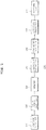
- FIG. 1 is a circuit diagram illustrating a power converter for a fuel cell according to an exemplary embodiment of the present invention.
- a power converter for a fuel cell includes a fuel cell 100, a boost converter L 1 , Q 1 , a bidirectional converter Q 2 , Q 3 , L 2 , an auxiliary energy storage device 200, an output capacitor C out , a load R load , a digital signal processor 300, and a controller 400.
- the power converter for the fuel cell performs an operation according to one of a normal operation mode of supplying a voltage needed according to a change of the load R load , and a diagnosis mode of predicting a lifespan of the fuel cell 100.
- the power converter for the fuel cell may control a voltage applied to the load R load in the normal operation mode, and perform a load leveling in response to an abrupt load change, etc.
- the load leveling compensates for load power using the power of the auxiliary energy storage device 200 when the power of the fuel cell 100 is smaller than the power which should be supplied to the load R load , and adjust the power which is excessively supplied to the load R load by charging surplus power to the auxiliary energy storage device 200 when the power of the fuel cell 100 is greater than the power which should be supplied to the load R load .
- the boost converter L 1 , Q 1 of the power converter for the fuel cell controls a load voltage so as to have a predetermined magnitude
- the bidirectional converter Q 2 , Q 3 , L 2 is used in order to handle the abrupt load change or a transient overload.
- the boost converter L 1 , Q 1 may boost a voltage output from the fuel cell 100 and control so as to maintain a constant magnitude
- the bidirectional converter Q 2 , Q 3 , L 2 may control in order to charge the power of the fuel cell 100 to the auxiliary energy storage device 200 by turning on or off the second switch Q 2 and the third switch Q 3 , or increase the load voltage by discharging the auxiliary energy storage device 200.
- the boost converter L1, Q 1 of the power converter for the fuel cell controls the load voltage so as to have the predetermined magnitude
- the bidirectional converter Q 2 , Q 3 , L 2 adds additional power to the power of the fuel cell 100 by charging the power of the fuel cell 100 to the auxiliary energy storage device 200 or discharging predetermined power from the auxiliary energy storage device 200 in order to handle the abrupt load change or the transient overload.
- the power converter for the fuel cell may perform an integral diagnosis using an electrochemical impedance spectroscopy (EIS) method.
- EIS electrochemical impedance spectroscopy
- the boost converter L 1 , Q 1 of the power converter for the fuel cell may perform an input current control in order to generate a perturbation current signal for performing the EIS method, and the bidirectional converter Q 2 , Q 3 , L 2 may control the load voltage.
- the boost converter L 1 , Q 1 and the bidirectional converter Q 2 , Q 3 , L 2 may be separately performed. This may be a prerequisite condition for successively measuring an impedance in spite of the load change.
- the boost converter L 1 , Q 1 makes a perturbation current
- the bidirectional converter Q 2 , Q 3 , L 2 controls the load voltage by charging or discharging the auxiliary energy storage device 200. Since the bidirectional converter Q 2 , Q 3 , L 2 is suitably controlled, a direct current (DC) level of the voltage output from the fuel cell 100 is not changed according to the change of the load R load .
- DC direct current
- a digital lock-in amplifier may be included in the digital signal processor (DSP), and be used for calculating the same phase and different phase components of the current perturbation and the voltage response, and an alternating current (AC) impedance of the fuel cell 100 for each frequency.
- An equivalent circuit parameter of the fuel cell 100 may be extracted from an impedance measured using a complex non-linear least square method. At this time, the extracted parameter may be used to predict the lifespan of the fuel cell. This may be implemented by comparing the extracted parameter and an initial parameter. A detailed description thereof will be described hereinafter.
- the controller 400 may perform an overall control of the power converter for the fuel cell.
- the controller 400 may switch the boost converter L 1 , Q 1 , and first, second, and third switches Q 1 , Q 2 , Q 3 included in the bidirectional converter Q 2 , Q 3 , L 2 , and control an operation of the digital signal processor 300.
- the controller 400 may control a circuit to operate either one of the normal operation mode or the diagnosis mode described above.
- the controller 400 may control a switching operation at a suitable timing, and control various operations of boosting by charging the power in the inductor L 1 included in the boost converter L 1 , Q 1 , or the inductor L 2 included in the bidirectional converter Q 2 , Q 3 , L 2 or discharging the power, etc.
- FIG. 2 is a control block diagram illustrating a digital signal processor included in a power converter for a fuel cell according to an exemplary embodiment of the present invention.
- the digital signal processor 300 may include a voltage detector 310, a digital lock-in amplifier 320, a memory 330, a parameter extractor 340, a parameter analyzer 350, a lifespan predictor 360, and a warning unit 370.
- the voltage detector 310 may detect a voltage of the fuel cell 100.
- the voltage detector 310 may detect a voltage for each frequency in which the boost converter L 1 , Q 1 induces from the fuel cell 100 by a signal of the digital signal processor 300. Meanwhile, the voltage detector 310 may operate by being substituted by a current and voltage detector 310, and be used as a block which can measure the voltage response by the current perturbation or the current response by the voltage perturbation.
- the digital lock-in amplifier 320 may calculate an impedance spectrum of the voltage for each frequency detected by the voltage detector 310.
- An AC signal received by the digital lock-in amplifier 320 is expressed by the following Equation 1.
- X n A sin 2 ⁇ f f s n + ⁇ + ⁇ A ne sin 2 ⁇ f ne f s n + ⁇ ne
- Equations 2 and 3 may be obtained by multiplying the detected signal X[n] by an in-phase signal C n and a quadrature-phase signal S n .
- the digital lock-in amplifier 320 may obtain a magnitude and a phase as shown in the following Equations 4 and 5 by filtering the AC components of the Equations 2 and 3.
- x 2 ⁇ I n ⁇ A cos ⁇ ;
- the memory 330 may store the impedance spectrum calculated by the digital lock-in amplifier 320.
- the parameter extractor 340 may select an equivalent circuit model of the fuel cell 100 according to the impedance spectrum extracted by the digital lock-in amplifier 320.
- the equivalent circuit model may be modeled by a Randles equivalent circuit which is well known. Referring to FIG. 3 , the equivalent circuit may be configured by two resistors R s , R p , and one capacitor C dl .
- the parameter extractor 340 may calculate an impedance of the equivalent circuit of the fuel cell 100 by the following Equation 6.
- Z ⁇ R s 1 + ⁇ C dl R p 2 + R p 1 + ⁇ C dl R p 2 + j ⁇ ⁇ C dl R p 2 1 + ⁇ C dl R p 2
- the parameter extractor 340 may calculate a parameter of the fuel cell 100 using a complex non-linear least square fitting method which is well known.
- the parameter extractor 340 may convert a complex impedance Z into each frequency function as shown in the following Equation 7.
- R s , R p , and C dl may be calculated by minimizing the following function " ⁇ ".
- y i represents actual measurement data
- Z(w) may be an impedance calculated by the equivalent model.
- ⁇ R s , ⁇ R p , and ⁇ C dl may be calculated by the Equations 8 and 10.
- R s , R p , and C dl may be updated by the ⁇ R s , ⁇ R p , and ⁇ C dl .
- the calculation may be continuously performed until the values are converged to a predetermined limit value (for example, 10-6) in order to obtain an optimum calculation value of the equivalent model parameter of a battery 2.
- the parameter analyzer 350 may analyze by comparing the impedance parameter extracted by the method described above and a reference parameter.
- the parameter analyzer 350 may analyze by comparing the extracted impedance parameter and a corresponding reference value.
- the impedance parameter may be R s , R p , C dl , etc.
- the lifespan predictor 360 may predict the lifespan of the fuel cell 100 according to the comparison result of the impedance parameter compared and analyzed by the parameter analyzer 350 and the reference parameter.
- the lifespan predictor 360 may be detected by comparing the impedance parameter of the fuel cell 100 and the corresponding reference value (the impedance parameter of a reference fuel cell 100).
- the impedance parameter of the fuel cell 100 has a difference with the corresponding reference value or does not have the difference, one the lifespan states may be allotted to the relevant fuel cell 100. For example, when the impedance of the fuel cell 100 is greater than the reference value in a range of a low frequency, an aging state of the fuel cell 100 may be worse than that of the fuel cell 100 having the impedance value which is equal to or less than the reference value.
- the aging state of the fuel cell 10 may be in relation with a magnitude of the difference between the calculated impedance parameter and the reference value.
- a magnitude of the difference between the calculated impedance parameter and the reference value is increased, it may be determined that the lifespan of the fuel cell 100 is decreased.
- the magnitude of the difference between the calculated impedance parameter and the reference value is decreased, it may be determined that the lifespan of the fuel cell 100 is good.
- the warning unit 370 may output a warning signal to the outside when the lifespan of the fuel cell 100 predicted by the lifespan predictor 360 is equal to or less than the predetermined reference value.
- the warning signal may be output by a method of generating an audio signal, or a method of displaying its state on an external display unit.
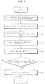
- FIG. 4 is a control flowchart of a power converter for a fuel cell according to an exemplary embodiment of the present invention.
- the power converter for the fuel cell may generate the perturbation current by the boost converter L 1 , Q 1 , and the perturbation current induced by the boost converter L 1 , Q 1 may be applied to the fuel cell 100 (400).
- the voltage detector 310 may detect the voltage of the fuel cell 100.
- the voltage detector 310 may detect the voltage for each frequency induced from the fuel cell 100 by the signal of the digital signal processor 100 (410).
- the digital lock-in amplifier 320 may calculate the impedance spectrum of the voltage for each frequency detected by the voltage detector 310. (420).
- the parameter extractor 340 may select the equivalent circuit model of the fuel cell 100 according to the impedance spectrum extracted by the digital lock-in amplifier 320.
- the equivalent circuit model may be modeled by the Randles equivalent circuit which is well known.
- the parameter extractor 340 may calculate the impedance of the equivalent circuit of the fuel cell 100 (430).
- the parameter analyzer 350 may analyze by comparing the impedance parameter extracted by the method described above and the reference parameter.
- the parameter analyzer 350 may analyze by comparing the extracted impedance parameter and the corresponding reference value.
- the lifespan predictor 360 may predict the lifespan of the fuel cell 100 according to the comparison result of the impedance parameter compared and analyzed by the parameter analyzer 350 and the reference parameter (440).
- the warning unit 370 may output the warning signal to the outside when the lifespan of the fuel cell 100 predicted by the lifespan predictor 360 is equal to or less than the predetermined reference value (450, 460).
Applications Claiming Priority (3)
| Application Number | Priority Date | Filing Date | Title |
|---|---|---|---|
| KR20130138059 | 2013-11-14 | ||
| KR1020140006993A KR101516419B1 (ko) | 2013-11-14 | 2014-01-21 | 연료전지용 전력변환장치 및 그 제어방법 |
| PCT/KR2014/007600 WO2015072653A1 (ko) | 2013-11-14 | 2014-08-14 | 연료전지용 전력변환장치 및 그 제어방법 |
Publications (3)
| Publication Number | Publication Date |
|---|---|
| EP2952923A1 EP2952923A1 (en) | 2015-12-09 |
| EP2952923A4 EP2952923A4 (en) | 2017-01-11 |
| EP2952923B1 true EP2952923B1 (en) | 2018-04-25 |
Family
ID=53393492
Family Applications (1)
| Application Number | Title | Priority Date | Filing Date |
|---|---|---|---|
| EP14862007.3A Active EP2952923B1 (en) | 2013-11-14 | 2014-08-14 | Power conversion device for fuel cell and method for controlling same |
Country Status (5)
| Country | Link |
|---|---|
| US (1) | US9786937B2 (ko) |
| EP (1) | EP2952923B1 (ko) |
| KR (1) | KR101516419B1 (ko) |
| CN (1) | CN105008948B (ko) |
| WO (1) | WO2015072653A1 (ko) |
Families Citing this family (11)
| Publication number | Priority date | Publication date | Assignee | Title |
|---|---|---|---|---|
| KR101637746B1 (ko) * | 2014-11-25 | 2016-07-20 | 현대자동차주식회사 | 연료전지 진단 장치 및 방법 |
| US10393818B2 (en) * | 2015-12-04 | 2019-08-27 | The Trustees Of Dartmouth College | Systems and methods for characterizing impedance of an energy storage device |
| KR101745208B1 (ko) * | 2015-12-14 | 2017-06-09 | 현대오트론 주식회사 | 연료 전지의 스택 상태 진단 장치 |
| DE102016106735A1 (de) * | 2016-04-12 | 2017-10-12 | Thyssenkrupp Marine Systems Gmbh | Ersatzschaltbasiertes Brennstoffzellen-Prognosemodell |
| KR101887787B1 (ko) * | 2016-12-09 | 2018-08-13 | 현대오트론 주식회사 | 연료전지 스택 진단용 교류 전류 생성 장치 및 방법 |
| US10992144B2 (en) * | 2017-05-17 | 2021-04-27 | Galley Power LLC | Battery balancing and current control with bypass circuit for load switch |
| WO2019010585A1 (en) * | 2017-07-13 | 2019-01-17 | The Governing Council Of The University Of Toronto | ELECTRICAL ARCHITECTURE OF ELECTROCHEMICAL IMPEDANCE SPECTROSCOPY |
| KR102119779B1 (ko) * | 2018-07-02 | 2020-06-09 | 현대자동차(주) | 연료전지의 전력 공급 시스템 및 그 제어방법 |
| DE202019102314U1 (de) | 2019-04-25 | 2020-07-29 | Aradex Ag | Vorrichtung mit wenigstens einer Brennstoffzelle |
| KR20210026102A (ko) | 2019-08-29 | 2021-03-10 | 주식회사 이진스 | 배터리 수명 예측 장치 및 그것의 동작 방법 |
| CN116256657B (zh) * | 2023-05-04 | 2024-04-12 | 同济大学 | 一种车载燃料电池交流阻抗在线测量系统和方法 |
Family Cites Families (9)
| Publication number | Priority date | Publication date | Assignee | Title |
|---|---|---|---|---|
| US6428918B1 (en) * | 2000-04-07 | 2002-08-06 | Avista Laboratories, Inc. | Fuel cell power systems, direct current voltage converters, fuel cell power generation methods, power conditioning methods and direct current power conditioning methods |
| KR100460881B1 (ko) * | 2002-06-28 | 2004-12-09 | 현대자동차주식회사 | 연료전지 하이브리드 전기자동차의 동력분배 제어시스템및 제어방법 |
| CN1731614A (zh) * | 2004-08-06 | 2006-02-08 | 三洋电机株式会社 | 燃料电池系统 |
| KR100868609B1 (ko) | 2006-12-11 | 2008-11-13 | 현대자동차주식회사 | 배터리 시스템이 적용되는 연료전지 슈퍼캡 하이브리드차량 및 이의 동력분배 제어 방법 |
| KR101201522B1 (ko) * | 2010-06-04 | 2012-11-14 | 세방전지(주) | 연료전지를 이용한 하이브리드 무정전 전원 시스템 및 그 제어방법 |
| US8981589B2 (en) * | 2010-08-24 | 2015-03-17 | GM Global Technology Operations LLC | Switched battery and capacitor arrangement and related operating methods |
| US8970176B2 (en) * | 2010-11-15 | 2015-03-03 | Bloom Energy Corporation | DC micro-grid |
| FR2975497B1 (fr) * | 2011-05-16 | 2013-06-28 | Centre Nat Rech Scient | Convertisseur electronique de puissance |
| KR101362580B1 (ko) | 2012-01-17 | 2014-02-14 | 세종공업 주식회사 | 연료전지 시스템 및 이의 시동방법 |
-
2014
- 2014-01-21 KR KR1020140006993A patent/KR101516419B1/ko active IP Right Grant
- 2014-08-14 WO PCT/KR2014/007600 patent/WO2015072653A1/ko active Application Filing
- 2014-08-14 CN CN201480011532.3A patent/CN105008948B/zh active Active
- 2014-08-14 US US14/767,573 patent/US9786937B2/en active Active
- 2014-08-14 EP EP14862007.3A patent/EP2952923B1/en active Active
Non-Patent Citations (1)
| Title |
|---|
| None * |
Also Published As
| Publication number | Publication date |
|---|---|
| EP2952923A4 (en) | 2017-01-11 |
| CN105008948B (zh) | 2018-02-16 |
| WO2015072653A1 (ko) | 2015-05-21 |
| KR101516419B1 (ko) | 2015-05-04 |
| US20160006061A1 (en) | 2016-01-07 |
| CN105008948A (zh) | 2015-10-28 |
| EP2952923A1 (en) | 2015-12-09 |
| US9786937B2 (en) | 2017-10-10 |
Similar Documents
| Publication | Publication Date | Title |
|---|---|---|
| EP2952923B1 (en) | Power conversion device for fuel cell and method for controlling same | |
| EP3186651B1 (en) | Electrochemical impedance spectroscopy in battery management systems | |
| Lee et al. | Online embedded impedance measurement using high-power battery charger | |
| Blanke et al. | Impedance measurements on lead–acid batteries for state-of-charge, state-of-health and cranking capability prognosis in electric and hybrid electric vehicles | |
| CN102411126B (zh) | 电池测量方法及装置 | |
| Kim et al. | On-line state-of-health estimation of Lithium-ion battery cells using frequency excitation | |
| US7323848B2 (en) | Battery charging state arithmetic operation device for calculating charging state of battery, and battery charging state arithmetic operation method | |
| Depernet et al. | Integration of electrochemical impedance spectroscopy functionality in proton exchange membrane fuel cell power converter | |
| US20180203073A1 (en) | System for providing an excitation signal to an electrochemical system and method therefor | |
| CN106997026B (zh) | 用于确定铅酸蓄电池的剩余电容量的方法和装置 | |
| Varnosfaderani et al. | Online impedance spectroscopy estimation of a battery | |
| Trovò et al. | Battery management system with testing protocols for kW-class vanadium redox flow batteries | |
| KR20060107473A (ko) | 임피던스 측정 및 개별 자동 충·방전 기능을 가진 축전지관리장치 | |
| CN108713152B (zh) | 用于确定锂离子电池的老化soh的方法 | |
| CN103760491A (zh) | 数字式蓄电池电量监测方法与装置 | |
| Benshatti et al. | Design and control of AC current injector for battery EIS measurement | |
| JP2019200094A (ja) | 蓄電池の劣化診断データ抽出装置及び蓄電池の劣化診断データ抽出方法 | |
| CN111755765A (zh) | 一种基于实时检测的锂离子电池变频脉冲充电方法和系统 | |
| JP2009146744A (ja) | 電池学習システム | |
| KR102509408B1 (ko) | 전기화학소자 스택의 임피던스 측정 장치 | |
| Beiranvand et al. | Review of Power Converter Topologies for Electrochemical Impedance Spectroscopy of Lithium-Ion Batteries | |
| Şanal et al. | Electrotechnical investigation of zinc-air cells for determination of cell-parameters for a battery management system | |
| Kallel et al. | Unipolar excitation signal with two phases for impedance spectroscopy of Li-ion battery cells | |
| Nguyen et al. | Design of a fuel cell power conditioning system for online diagnosis and load leveling | |
| Eddahech et al. | Ultracapacitor performance determination using dynamic model parameter identification |
Legal Events
| Date | Code | Title | Description |
|---|---|---|---|
| PUAI | Public reference made under article 153(3) epc to a published international application that has entered the european phase |
Free format text: ORIGINAL CODE: 0009012 |
|
| 17P | Request for examination filed |
Effective date: 20150901 |
|
| AK | Designated contracting states |
Kind code of ref document: A1 Designated state(s): AL AT BE BG CH CY CZ DE DK EE ES FI FR GB GR HR HU IE IS IT LI LT LU LV MC MK MT NL NO PL PT RO RS SE SI SK SM TR |
|
| AX | Request for extension of the european patent |
Extension state: BA ME |
|
| A4 | Supplementary search report drawn up and despatched |
Effective date: 20161213 |
|
| RIC1 | Information provided on ipc code assigned before grant |
Ipc: G05F 3/24 20060101AFI20161207BHEP Ipc: H01M 8/04828 20160101ALI20161207BHEP Ipc: G01R 31/36 20060101ALN20161207BHEP Ipc: H01M 8/04537 20160101ALI20161207BHEP |
|
| DAX | Request for extension of the european patent (deleted) | ||
| 17Q | First examination report despatched |
Effective date: 20170728 |
|
| REG | Reference to a national code |
Ref country code: DE Ref legal event code: R079 Ref document number: 602014024683 Country of ref document: DE Free format text: PREVIOUS MAIN CLASS: G01R0031400000 Ipc: G05F0003240000 |
|
| GRAP | Despatch of communication of intention to grant a patent |
Free format text: ORIGINAL CODE: EPIDOSNIGR1 |
|
| RIC1 | Information provided on ipc code assigned before grant |
Ipc: G01R 31/36 20060101ALN20171005BHEP Ipc: H01M 8/04828 20160101ALI20171005BHEP Ipc: H01M 8/04537 20160101ALI20171005BHEP Ipc: G05F 3/24 20060101AFI20171005BHEP |
|
| INTG | Intention to grant announced |
Effective date: 20171109 |
|
| GRAA | (expected) grant |
Free format text: ORIGINAL CODE: 0009210 |
|
| GRAS | Grant fee paid |
Free format text: ORIGINAL CODE: EPIDOSNIGR3 |
|
| AK | Designated contracting states |
Kind code of ref document: B1 Designated state(s): AL AT BE BG CH CY CZ DE DK EE ES FI FR GB GR HR HU IE IS IT LI LT LU LV MC MK MT NL NO PL PT RO RS SE SI SK SM TR |
|
| REG | Reference to a national code |
Ref country code: GB Ref legal event code: FG4D |
|
| REG | Reference to a national code |
Ref country code: CH Ref legal event code: EP |
|
| REG | Reference to a national code |
Ref country code: AT Ref legal event code: REF Ref document number: 993566 Country of ref document: AT Kind code of ref document: T Effective date: 20180515 |
|
| REG | Reference to a national code |
Ref country code: IE Ref legal event code: FG4D |
|
| REG | Reference to a national code |
Ref country code: DE Ref legal event code: R096 Ref document number: 602014024683 Country of ref document: DE |
|
| REG | Reference to a national code |
Ref country code: FR Ref legal event code: PLFP Year of fee payment: 5 |
|
| REG | Reference to a national code |
Ref country code: NL Ref legal event code: MP Effective date: 20180425 |
|
| REG | Reference to a national code |
Ref country code: LT Ref legal event code: MG4D |
|
| PG25 | Lapsed in a contracting state [announced via postgrant information from national office to epo] |
Ref country code: NL Free format text: LAPSE BECAUSE OF FAILURE TO SUBMIT A TRANSLATION OF THE DESCRIPTION OR TO PAY THE FEE WITHIN THE PRESCRIBED TIME-LIMIT Effective date: 20180425 |
|
| PG25 | Lapsed in a contracting state [announced via postgrant information from national office to epo] |
Ref country code: ES Free format text: LAPSE BECAUSE OF FAILURE TO SUBMIT A TRANSLATION OF THE DESCRIPTION OR TO PAY THE FEE WITHIN THE PRESCRIBED TIME-LIMIT Effective date: 20180425 Ref country code: PL Free format text: LAPSE BECAUSE OF FAILURE TO SUBMIT A TRANSLATION OF THE DESCRIPTION OR TO PAY THE FEE WITHIN THE PRESCRIBED TIME-LIMIT Effective date: 20180425 Ref country code: LT Free format text: LAPSE BECAUSE OF FAILURE TO SUBMIT A TRANSLATION OF THE DESCRIPTION OR TO PAY THE FEE WITHIN THE PRESCRIBED TIME-LIMIT Effective date: 20180425 Ref country code: NO Free format text: LAPSE BECAUSE OF FAILURE TO SUBMIT A TRANSLATION OF THE DESCRIPTION OR TO PAY THE FEE WITHIN THE PRESCRIBED TIME-LIMIT Effective date: 20180725 Ref country code: BG Free format text: LAPSE BECAUSE OF FAILURE TO SUBMIT A TRANSLATION OF THE DESCRIPTION OR TO PAY THE FEE WITHIN THE PRESCRIBED TIME-LIMIT Effective date: 20180725 Ref country code: SE Free format text: LAPSE BECAUSE OF FAILURE TO SUBMIT A TRANSLATION OF THE DESCRIPTION OR TO PAY THE FEE WITHIN THE PRESCRIBED TIME-LIMIT Effective date: 20180425 Ref country code: FI Free format text: LAPSE BECAUSE OF FAILURE TO SUBMIT A TRANSLATION OF THE DESCRIPTION OR TO PAY THE FEE WITHIN THE PRESCRIBED TIME-LIMIT Effective date: 20180425 |
|
| PG25 | Lapsed in a contracting state [announced via postgrant information from national office to epo] |
Ref country code: GR Free format text: LAPSE BECAUSE OF FAILURE TO SUBMIT A TRANSLATION OF THE DESCRIPTION OR TO PAY THE FEE WITHIN THE PRESCRIBED TIME-LIMIT Effective date: 20180726 Ref country code: RS Free format text: LAPSE BECAUSE OF FAILURE TO SUBMIT A TRANSLATION OF THE DESCRIPTION OR TO PAY THE FEE WITHIN THE PRESCRIBED TIME-LIMIT Effective date: 20180425 Ref country code: LV Free format text: LAPSE BECAUSE OF FAILURE TO SUBMIT A TRANSLATION OF THE DESCRIPTION OR TO PAY THE FEE WITHIN THE PRESCRIBED TIME-LIMIT Effective date: 20180425 Ref country code: HR Free format text: LAPSE BECAUSE OF FAILURE TO SUBMIT A TRANSLATION OF THE DESCRIPTION OR TO PAY THE FEE WITHIN THE PRESCRIBED TIME-LIMIT Effective date: 20180425 |
|
| REG | Reference to a national code |
Ref country code: AT Ref legal event code: MK05 Ref document number: 993566 Country of ref document: AT Kind code of ref document: T Effective date: 20180425 |
|
| PG25 | Lapsed in a contracting state [announced via postgrant information from national office to epo] |
Ref country code: PT Free format text: LAPSE BECAUSE OF FAILURE TO SUBMIT A TRANSLATION OF THE DESCRIPTION OR TO PAY THE FEE WITHIN THE PRESCRIBED TIME-LIMIT Effective date: 20180827 |
|
| REG | Reference to a national code |
Ref country code: DE Ref legal event code: R097 Ref document number: 602014024683 Country of ref document: DE |
|
| PG25 | Lapsed in a contracting state [announced via postgrant information from national office to epo] |
Ref country code: CZ Free format text: LAPSE BECAUSE OF FAILURE TO SUBMIT A TRANSLATION OF THE DESCRIPTION OR TO PAY THE FEE WITHIN THE PRESCRIBED TIME-LIMIT Effective date: 20180425 Ref country code: SK Free format text: LAPSE BECAUSE OF FAILURE TO SUBMIT A TRANSLATION OF THE DESCRIPTION OR TO PAY THE FEE WITHIN THE PRESCRIBED TIME-LIMIT Effective date: 20180425 Ref country code: EE Free format text: LAPSE BECAUSE OF FAILURE TO SUBMIT A TRANSLATION OF THE DESCRIPTION OR TO PAY THE FEE WITHIN THE PRESCRIBED TIME-LIMIT Effective date: 20180425 Ref country code: AT Free format text: LAPSE BECAUSE OF FAILURE TO SUBMIT A TRANSLATION OF THE DESCRIPTION OR TO PAY THE FEE WITHIN THE PRESCRIBED TIME-LIMIT Effective date: 20180425 Ref country code: DK Free format text: LAPSE BECAUSE OF FAILURE TO SUBMIT A TRANSLATION OF THE DESCRIPTION OR TO PAY THE FEE WITHIN THE PRESCRIBED TIME-LIMIT Effective date: 20180425 Ref country code: RO Free format text: LAPSE BECAUSE OF FAILURE TO SUBMIT A TRANSLATION OF THE DESCRIPTION OR TO PAY THE FEE WITHIN THE PRESCRIBED TIME-LIMIT Effective date: 20180425 |
|
| PG25 | Lapsed in a contracting state [announced via postgrant information from national office to epo] |
Ref country code: SM Free format text: LAPSE BECAUSE OF FAILURE TO SUBMIT A TRANSLATION OF THE DESCRIPTION OR TO PAY THE FEE WITHIN THE PRESCRIBED TIME-LIMIT Effective date: 20180425 Ref country code: IT Free format text: LAPSE BECAUSE OF FAILURE TO SUBMIT A TRANSLATION OF THE DESCRIPTION OR TO PAY THE FEE WITHIN THE PRESCRIBED TIME-LIMIT Effective date: 20180425 |
|
| PLBE | No opposition filed within time limit |
Free format text: ORIGINAL CODE: 0009261 |
|
| STAA | Information on the status of an ep patent application or granted ep patent |
Free format text: STATUS: NO OPPOSITION FILED WITHIN TIME LIMIT |
|
| PG25 | Lapsed in a contracting state [announced via postgrant information from national office to epo] |
Ref country code: MC Free format text: LAPSE BECAUSE OF FAILURE TO SUBMIT A TRANSLATION OF THE DESCRIPTION OR TO PAY THE FEE WITHIN THE PRESCRIBED TIME-LIMIT Effective date: 20180425 |
|
| REG | Reference to a national code |
Ref country code: CH Ref legal event code: PL |
|
| 26N | No opposition filed |
Effective date: 20190128 |
|
| PG25 | Lapsed in a contracting state [announced via postgrant information from national office to epo] |
Ref country code: CH Free format text: LAPSE BECAUSE OF NON-PAYMENT OF DUE FEES Effective date: 20180831 Ref country code: LU Free format text: LAPSE BECAUSE OF NON-PAYMENT OF DUE FEES Effective date: 20180814 Ref country code: LI Free format text: LAPSE BECAUSE OF NON-PAYMENT OF DUE FEES Effective date: 20180831 |
|
| REG | Reference to a national code |
Ref country code: BE Ref legal event code: MM Effective date: 20180831 |
|
| REG | Reference to a national code |
Ref country code: IE Ref legal event code: MM4A |
|
| PG25 | Lapsed in a contracting state [announced via postgrant information from national office to epo] |
Ref country code: SI Free format text: LAPSE BECAUSE OF FAILURE TO SUBMIT A TRANSLATION OF THE DESCRIPTION OR TO PAY THE FEE WITHIN THE PRESCRIBED TIME-LIMIT Effective date: 20180425 |
|
| PG25 | Lapsed in a contracting state [announced via postgrant information from national office to epo] |
Ref country code: IE Free format text: LAPSE BECAUSE OF NON-PAYMENT OF DUE FEES Effective date: 20180814 |
|
| PG25 | Lapsed in a contracting state [announced via postgrant information from national office to epo] |
Ref country code: BE Free format text: LAPSE BECAUSE OF NON-PAYMENT OF DUE FEES Effective date: 20180831 |
|
| PG25 | Lapsed in a contracting state [announced via postgrant information from national office to epo] |
Ref country code: AL Free format text: LAPSE BECAUSE OF FAILURE TO SUBMIT A TRANSLATION OF THE DESCRIPTION OR TO PAY THE FEE WITHIN THE PRESCRIBED TIME-LIMIT Effective date: 20180425 |
|
| PG25 | Lapsed in a contracting state [announced via postgrant information from national office to epo] |
Ref country code: MT Free format text: LAPSE BECAUSE OF NON-PAYMENT OF DUE FEES Effective date: 20180814 |
|
| PG25 | Lapsed in a contracting state [announced via postgrant information from national office to epo] |
Ref country code: TR Free format text: LAPSE BECAUSE OF FAILURE TO SUBMIT A TRANSLATION OF THE DESCRIPTION OR TO PAY THE FEE WITHIN THE PRESCRIBED TIME-LIMIT Effective date: 20180425 |
|
| PG25 | Lapsed in a contracting state [announced via postgrant information from national office to epo] |
Ref country code: HU Free format text: LAPSE BECAUSE OF FAILURE TO SUBMIT A TRANSLATION OF THE DESCRIPTION OR TO PAY THE FEE WITHIN THE PRESCRIBED TIME-LIMIT; INVALID AB INITIO Effective date: 20140814 Ref country code: CY Free format text: LAPSE BECAUSE OF FAILURE TO SUBMIT A TRANSLATION OF THE DESCRIPTION OR TO PAY THE FEE WITHIN THE PRESCRIBED TIME-LIMIT Effective date: 20180425 Ref country code: MK Free format text: LAPSE BECAUSE OF NON-PAYMENT OF DUE FEES Effective date: 20180425 |
|
| PG25 | Lapsed in a contracting state [announced via postgrant information from national office to epo] |
Ref country code: IS Free format text: LAPSE BECAUSE OF FAILURE TO SUBMIT A TRANSLATION OF THE DESCRIPTION OR TO PAY THE FEE WITHIN THE PRESCRIBED TIME-LIMIT Effective date: 20180825 |
|
| PGFP | Annual fee paid to national office [announced via postgrant information from national office to epo] |
Ref country code: FR Payment date: 20230608 Year of fee payment: 10 |
|
| PGFP | Annual fee paid to national office [announced via postgrant information from national office to epo] |
Ref country code: GB Payment date: 20230622 Year of fee payment: 10 |
|
| PGFP | Annual fee paid to national office [announced via postgrant information from national office to epo] |
Ref country code: DE Payment date: 20230620 Year of fee payment: 10 |