EP2952875A1 - Gerät und verfahren zur messung einer aerosolkonzentration in einem gasförmigen medium - Google Patents
Gerät und verfahren zur messung einer aerosolkonzentration in einem gasförmigen medium Download PDFInfo
- Publication number
- EP2952875A1 EP2952875A1 EP15001651.7A EP15001651A EP2952875A1 EP 2952875 A1 EP2952875 A1 EP 2952875A1 EP 15001651 A EP15001651 A EP 15001651A EP 2952875 A1 EP2952875 A1 EP 2952875A1
- Authority
- EP
- European Patent Office
- Prior art keywords
- vibrating beam
- measuring
- vibrating
- nanoparticles
- gaseous medium
- Prior art date
- Legal status (The legal status is an assumption and is not a legal conclusion. Google has not performed a legal analysis and makes no representation as to the accuracy of the status listed.)
- Granted
Links
Images





Classifications
-
- G—PHYSICS
- G01—MEASURING; TESTING
- G01N—INVESTIGATING OR ANALYSING MATERIALS BY DETERMINING THEIR CHEMICAL OR PHYSICAL PROPERTIES
- G01N15/00—Investigating characteristics of particles; Investigating permeability, pore-volume or surface-area of porous materials
- G01N15/06—Investigating concentration of particle suspensions
- G01N15/0606—Investigating concentration of particle suspensions by collecting particles on a support
-
- G—PHYSICS
- G01—MEASURING; TESTING
- G01G—WEIGHING
- G01G3/00—Weighing apparatus characterised by the use of elastically-deformable members, e.g. spring balances
- G01G3/12—Weighing apparatus characterised by the use of elastically-deformable members, e.g. spring balances wherein the weighing element is in the form of a solid body stressed by pressure or tension during weighing
- G01G3/16—Weighing apparatus characterised by the use of elastically-deformable members, e.g. spring balances wherein the weighing element is in the form of a solid body stressed by pressure or tension during weighing measuring variations of frequency of oscillations of the body
- G01G3/165—Constructional details
-
- G—PHYSICS
- G01—MEASURING; TESTING
- G01N—INVESTIGATING OR ANALYSING MATERIALS BY DETERMINING THEIR CHEMICAL OR PHYSICAL PROPERTIES
- G01N5/00—Analysing materials by weighing, e.g. weighing small particles separated from a gas or liquid
- G01N5/02—Analysing materials by weighing, e.g. weighing small particles separated from a gas or liquid by absorbing or adsorbing components of a material and determining change of weight of the adsorbent, e.g. determining moisture content
-
- G—PHYSICS
- G01—MEASURING; TESTING
- G01N—INVESTIGATING OR ANALYSING MATERIALS BY DETERMINING THEIR CHEMICAL OR PHYSICAL PROPERTIES
- G01N1/00—Sampling; Preparing specimens for investigation
- G01N1/02—Devices for withdrawing samples
- G01N1/22—Devices for withdrawing samples in the gaseous state
- G01N1/2202—Devices for withdrawing samples in the gaseous state involving separation of sample components during sampling
- G01N1/2205—Devices for withdrawing samples in the gaseous state involving separation of sample components during sampling with filters
-
- G—PHYSICS
- G01—MEASURING; TESTING
- G01N—INVESTIGATING OR ANALYSING MATERIALS BY DETERMINING THEIR CHEMICAL OR PHYSICAL PROPERTIES
- G01N1/00—Sampling; Preparing specimens for investigation
- G01N1/02—Devices for withdrawing samples
- G01N1/22—Devices for withdrawing samples in the gaseous state
- G01N1/2202—Devices for withdrawing samples in the gaseous state involving separation of sample components during sampling
- G01N1/2208—Devices for withdrawing samples in the gaseous state involving separation of sample components during sampling with impactors
-
- G—PHYSICS
- G01—MEASURING; TESTING
- G01N—INVESTIGATING OR ANALYSING MATERIALS BY DETERMINING THEIR CHEMICAL OR PHYSICAL PROPERTIES
- G01N1/00—Sampling; Preparing specimens for investigation
- G01N1/02—Devices for withdrawing samples
- G01N1/22—Devices for withdrawing samples in the gaseous state
- G01N1/2202—Devices for withdrawing samples in the gaseous state involving separation of sample components during sampling
- G01N2001/222—Other features
- G01N2001/2223—Other features aerosol sampling devices
-
- G—PHYSICS
- G01—MEASURING; TESTING
- G01N—INVESTIGATING OR ANALYSING MATERIALS BY DETERMINING THEIR CHEMICAL OR PHYSICAL PROPERTIES
- G01N15/00—Investigating characteristics of particles; Investigating permeability, pore-volume or surface-area of porous materials
- G01N2015/0038—Investigating nanoparticles
-
- G—PHYSICS
- G01—MEASURING; TESTING
- G01N—INVESTIGATING OR ANALYSING MATERIALS BY DETERMINING THEIR CHEMICAL OR PHYSICAL PROPERTIES
- G01N15/00—Investigating characteristics of particles; Investigating permeability, pore-volume or surface-area of porous materials
- G01N2015/0042—Investigating dispersion of solids
- G01N2015/0046—Investigating dispersion of solids in gas, e.g. smoke
Definitions
- Nanotechnology is a fast-growing area of science and industry. Nanoparticles, ie particles with a size of typically 1 to 1000 nanometers, are already found in a variety of applications today. For example, nanoparticles or nanotechnology are commonly used in electronics, monitors, batteries, automobiles, aerospace or healthcare.
- Elements of a generic device for measuring an aerosol concentration for example, from the article of HS Wasisto et al.
- Portable cantilever-based airborne nanoparticle detector published in Sensors and Actuators B 187 (2013), 118-127 , known.
- the article describes a measuring cell with an inlet opening and an outlet opening, in which a vibrating beam or cantilever made of silicon is arranged.
- the vibrating beam is vibrated by a piezoelectric element by applying a sinusoidal voltage to the piezoelectric element.
- a piezoresistive Wheatstone bridge integrated in the vibrating beam the generated oscillation can be read out and thus the resonance frequency can be determined.
- the resonance frequency of the vibrating beam depends on its mass, this is influenced by the attachment of nanoparticles.
- a potential applied to the vibrating beam charged nanoparticles experience a force directed towards the vibrating beam, are deposited thereon and thus influence its resonance frequency.
- the change of the resonance frequency over a certain period of time can thus serve as a measure of the nanoparticles deposited in the same period. Indirectly, conclusions can be drawn about the nanoparticle concentration in the ambient air.
- the invention solves the problem by a generic device for measuring an aerosol concentration in a gaseous medium whose excitation device comprises an electrothermal element, which the vibrating beam to vibrate when an oscillating voltage is applied to the electrothermal element.
- the AC voltage can be superimposed on a DC component.
- the problem is further solved by a generic method for measuring an aerosol concentration in a gaseous medium, in which the vibrating beam is excited by means of an electrothermal element.
- the invention is not a piezoelectric element but an electrothermal element, e.g. a heating resistor, used to excite the vibrating beam. It has been found that in this way a defined region of the vibrating beam, in which the nanoparticles attach and a lower tendency of nanoparticles adhering to the vibrating beam to detach again from the vibrating beam, can be achieved. Due to the electrothermal excitation of the vibrating beam, a bending vibration can be achieved in-plane with a high quality factor, ie in a plane with the separation surface of the nanoparticles. "Out-of-plane" accordingly designates the direction of oscillation which is perpendicular to the plane of the separation surface.
- an electrothermal element e.g. a heating resistor
- the in-plane deflection may be about 25 times less than out-of-plane.
- the smallest possible movement in the vibrating beam is desirable in order to minimize centrifugal forces on the adhering nanoparticles and thus to prevent possible detachment.
- the vibrating beam can be controlled in combination with the oscillating voltage or with the oscillating current controlled to vibrate.
- the oscillation frequency corresponds to the frequency at which the voltage / current oscillates.
- An oscillating voltage in this case means a periodically changed voltage, which may be, for example, a sinusoidal, triangular or rectangular voltage.
- the oscillating voltage can be designed such that a potential is periodically applied and switched off again, so that periods of current flow and corresponding heating with periods without current flow and thus a cooling of the electrothermal element alternate.
- the temperature differences achieved in each period can be in the range of a few degrees centigrade.
- a vibrating beam of silicon having a size of e.g. 1,000 ⁇ m x 170 ⁇ m x 15-20 ⁇ m (length x width x thickness) typically has a resonant frequency in the range of 200 kHz. Larger swing beams are possible as well as smaller dimensions.
- the resonance frequency is e.g. in the range of about 10 kHz.
- this can be done by applying a substantially constant potential difference of at least 200 V with respect to ground potential to the vibrating bars by means of a voltage source. Since a part of the nanoparticles present as aerosol normally has an electrical charge, a force directed onto the vibrating beam can be exerted on these nanoparticles by the electric field thus generated by electrophoresis, so that they preferably attach to the vibrating beam. A higher potential difference of e.g. at least 500 V increases the applied force and thus the yield of nanoparticles. If a negative potential is applied, positively charged nanoparticles are deposited and vice versa. On average, the same number of positively charged and negatively charged nanoparticles are present in the air, so that generally no sign of the applied potential is preferred. Alternatively, the state of charge of the analyzed aerosol can be adjusted by an upstream charging stage.
- thermophoresis Another way to transport the nanoparticles in the direction of the vibrating beam is the thermophoresis.
- a heating element which can be heated to a temperature of at least 100 ° C, preferably of at least 400 ° C, be used to generate a negative temperature gradient in the direction of the vibrating beam.
- a negative temperature gradient in the direction of the vibrating beam means that the immediate ambient temperature of the vibrating beam is lower than the outer regions of the temperature field.
- a heating element can be mounted circumferentially around the vibrating beam in order to produce a corresponding temperature gradient, for example by means of a heating coil which is arranged symmetrically around the vibrating beam.
- nanoparticles can enter the zone immediately around the vibrating beam and then at "switched on" Temperaturgradienten then be driven onto the vibrating beam.
- Thermophoresis has the advantage that it does not rely on an electric charge of the particles to be detected. Both methods can be combined to trap the nanoparticles to be detected. In addition, with thermophoresis preferably very small nanoparticles are detected with diameters smaller than 20 nm.
- the device further comprises a device for generating a gas flow of the gaseous medium through the measuring device. It is continuously added and removed ambient air. As a result of the inevitable turbulences, more nanoparticles come into contact with the vibrating beam, so that the yield is further increased.
- the device for generating a gas flow may be a fan, which has advantages due to its compact design. The use of e.g. But a pump is also conceivable.
- the vibrating beam consists of a doped semiconductor material and on at least one surface of the vibrating beam a surface is formed, which has a higher doping than a main body of the vibrating beam, so that at a voltage applied to this surface negative or positive potential aerosols preferentially deposit on this.
- an electrode made of p-doped material may be provided, while the base material of the vibrating beam consists of n-doped material, for example of n-doped silicon.
- Such a vibrating beam is then designed to collect positively or negatively charged particles, so that for electrophoresis a negative or positive potential must be applied to the vibrating beam.
- a filter at the inlet of the measuring cell.
- the larger particles or particle agglomerates are thus prevented from penetrating into the measuring cell.
- Such a filter may have a pore size of for example 5 microns.
- the filter preferably has a pore size of not more than 2.5 ⁇ m. It may be z, B. to act a microfilter, which consists of a silicon membrane with etched holes. The membrane thickness and thus the height of the hole wall can be determined by e.g.
- a so-called impactor is a simple, possibly circular plate, which is arranged centrally in the gas or air flow between the inlet opening and the vibrating beam is.
- a flow is formed, which preferably carries lighter particles, ie mainly the nanoparticles to be detected, with it. Larger particles bounce on the impactor because of their greater inertia and are deposited there. They are thus removed from the gas stream and can no longer reach the vibrating beam.
- the distance of the impactor to the inlet opening is variable, so that the meter can be adapted to different environmental conditions such as different particle sizes or materials to be detected such as artificial nanoparticles in the workplace or soot particles in traffic.
- the yield of attached nanoparticles can be further increased if the surface of the vibrating beam has a nanostructuring.
- This can e.g. consisting of arranged on the surface of the vibrating beam nanocolumns with diameters of typically 300 nm, heights of 1 to 2 microns in a grid of typically 500 nm.
- the production on the vibrating beam is possible, for example, by a combination of nanoimprint lithography for structuring the nanopillars and photolithography for structuring the vibrating bars. Either the photolithography process first and then the nanoimprint process or, preferably, the nanoimprint process first and then the photolithography process can be performed. Due to the significantly enlarged surface, more particles come into contact with the vibrating beam and can accumulate on it.
- the measuring device for determining the resonant frequency of the vibrating beam may comprise a Wheatstone bridge. This can be carried out integrally with the vibrating beam.
- the Wheatstone bridge comprises a piezoresistive element that provides an output voltage depending on the bending state of the vibrating beam.
- the Wheatstone bridge When a constant voltage is applied to the Wheatstone bridge, the Wheatstone bridge will deliver at its output due to its dependence on the bending state of the vibrating beam changing electrical resistance a oscillating with the current vibration frequency of the vibrating beam signal so that the frequency of the vibration can be measured, via suitable measuring or control mechanisms, then the actual resonant frequency f 0 and the change .DELTA.f 0 can be determined in a time interval .DELTA.t 0 / ⁇ t can then be determined by means of a suitable calibration, the aerosol concentration in the surrounding medium.
- the measurement of ⁇ f 0 / ⁇ t occurs cyclically alternating with the electrophoretic or thermophoretic particle collection: During the measurement, the collection voltage is switched off and during the particle collection the oscillation excitation is switched off.
- the measuring device for determining the resonant frequency of the vibrating beam comprises a phase locked loop (PLL).
- PLL phase locked loop
- the excitation frequency can be changed until the amplitude has a maximum. Then the current resonance frequency is set. It can thus track the resonant frequency of the vibrating beam and recorded their shift.
- the phase-locked loop consists essentially of a phase detector, a loop filter and a voltage-controlled oscillator.
- Support electronics may consist of a preamplifier for signal amplification at the resonator output.
- the excitation device like the Wheatstone bridge, may be integral with the vibrating beam.
- the vibrating beam is then a self-exciting, self-detecting resonator or cantilever.
- Other components to complete the meter may be an energy distribution network be with a high-voltage module, a portable housing in handheld format as well as a microcontroller and display.
- a microcontroller and display Such a prototype has already been produced and tested by the inventors. Thus, for the first time, an extremely compact, highly accurate, easy-to-use and energy-saving device for measuring aerosol concentration in the ambient air was produced.
- the device may e.g. powered by three standard 1.5V batteries or batteries
- the power distribution network provides power to the excitation unit, the microcontroller, and the display, and also includes a high voltage module that powers the electrophoresis unit.
- the high voltage for the electrophoresis unit may e.g. be controllable in the range of 230 V to 930 V by low power consumption of e.g. 0.04 W to 0.28 W results in a long runtime of the device.
- a microcontroller can retrieve the data from the frequency measurement system, e.g. So record from the phase locked loop, further processed and bring in a meaningful for the end user presentation. So it can be e.g. the measured frequency shift of the vibrating beam, on which nanoparticles have deposited, against the resonance frequency of the "naked" vibrating beam and the calculated mass concentration of nanoparticles in the ambient air are displayed. Further evaluations, e.g. a graphical representation of the measured mass concentration as a function of time, are also conceivable and provided.
- the vibrating beam can be exchanged by the user himself, if this is reversibly plugged into the meter without further fasteners.
- Spring-loaded contact tips can then provide both the electrical contact as well as a mechanical attachment.
- the vibrating beams can be reused if they have been cleaned accordingly. This is possible, for example, dry with a stream of gaseous nitrogen or in a wet process. It is easy to carry out a cleaning in an ultrasonic bath, for example with acetone or deionized water as the liquid medium. Also conceivable is a vibrating beam, which has a thin sacrificial layer, which is then removed during cleaning together with the nanoparticles adhering thereto.
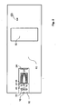
- FIG. 1 shows an embodiment of an inventive device for measuring an aerosol concentration.
- the measuring cell 10 is flowed through by the gas to be examined.
- the gas enters through the inlet opening 12 and out of the measuring cell through the outlet opening 14.
- the fan 24 ensures a continuous gas flow through the measuring cell 10
- Within the measuring cell of the vibrating beam 30 is arranged.
- the aerosols or nanoparticles entrained by the gas stream are deposited at least partially on the vibrating beam 30. The thus changed mass of the vibrating beam 30 influences its resonant frequency.
- the particle filter 16 which partially closes the inlet opening 12, is arranged at the inlet opening 12.
- the particle filter 16 covers with its cross section the cross section of the inlet opening 12 and has openings which are on the order of the largest particles to be detected. Larger particles are prevented by the particle filter or microfilter 16 from penetrating into the measuring cell 10.
- an impactor 20 is arranged between the vibrating beam 30 and the inlet opening 12. This is positioned so that it blocks the shortest path from the inlet opening 12 to the vibrating beam 30. There is therefore a gas flow around the impactor 20 around. Lighter and therefore smaller particles are guided by the gas flow around the impactor 20, whereas larger and therefore heavier particles impact the impactor 20, where they are deposited or "impacted” and thus removed from the gas stream.
- a counter electrode 40 is arranged on several sides of the oscillating beam 30. It can be executed around the vibrating beam 30 encircling and, for example, annular.
- the counterelectrode 40 can be used by applying an electrical potential to exert by means of electrophoresis a directed in the direction of the vibrating beam 30 force on the particles to be detected.
- a temperature gradient within the measuring cell 10 can be generated by optionally periodically heating the counter electrode 40, which likewise leads to a deposition of the particles to be detected on the vibrating beam 30 due to thermophoresis.
- a boundary 26 separates the sensor mounting area from the particle collector.
- the measuring cell 10 also has spring-loaded contact pins 31, which both fix the vibrating beam 30 and electrically contact. It is such a simple change of the swing beam 30 without expensive soldering, screw or other fixing measures possible.
- the contact pins 31 go into pins 32, with which a connection to the housing 60 can be made.
- On top of the housing 60 an LCD display 62 and an on / off switch 64 are provided.
- the housing itself contains a high-voltage module 68, a battery 70 and various measuring, regulating and storage circuits 66.
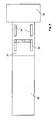
- FIG. 2 shows a plan view of the device according to FIG. 1 ,
- the measuring cell 10 with the microfilter 16, the impactor 20, the counter electrode 40, the vibrating beam 30, the spring-loaded contact pins 31 and the fan 24 can be seen ,
- the boundary 26 also separates the sensor mounting area from the particle collector here.
- FIG. 3 shows a schematic representation of a microfilter 16.
- the microfilter 16 consists of a filter frame 19 which carries a silicon membrane 18, which has a thickness of 12 microns.
- a silicon membrane 18 which has a thickness of 12 microns.
- holes 17 are etched.
- the holes 17 have a diameter of 2.5 microns.
- the representation is not to scale.
- FIG. 4 shows an impactor 20 which is secured by means of the impactor holder 21 in the impactor frame 22.
- the vibrating beam 30 in the assembled state of the device according to the invention, is in the flow direction of the gas flow centrally behind the impactor 20.
- a particle that attaches to the vibrating beam must thus pass the impactor 20 in the radially outer region of the measuring cell 10 and then a movement inwards to perform on the vibrating beam 30. This is all the more likely the smaller and thus lighter the particles are. Larger particles impact against the impactor 20 with high probability and are thus removed from the gas flow, or leave the measuring cell through the outlet opening again.
- FIG. 5 shows an enlarged view of a vibrating beam or cantilever 30 according to the invention in the left part of the figure, the p-type nanoparticle collecting surface 38 can be seen at which the nanoparticles are deposited.
- the existing silicon mounting frame 39 for attachment of the swing beam 30 and for receiving the contacts to see.
- the right region of the vibrating beam 30 is designed as an n-conducting region 37.
- n-conducting region 37 are a p-type, U-shaped piezoresistive Wheatstone bridge 52 and two p-type heating resistors 34.
- the heating resistors 34 are acted upon by an oscillating voltage, so that a corresponding current through the resistors 34 flows.
- the resistors 34 periodically expand and the vibrating beam 30 is vibrated.
- the Wheatstone bridge 52 the current frequency can be read out.
- the resonance frequency can then be determined,
- FIG. 6 shows a side sectional view of the vibrating beam 30 according to FIG. 5 , Again, it can be seen that the vibrating beam 30 is constructed for the most part of n-type silicon 37.
- the heating resistors 34 and the Wheatstone bridge 52 it can be seen here that 30 metal contacts 36, which consist of chromium and gold, are applied to the vibrating beam. In each case under these electrical contacts 36 p + -doped areas for producing the ohmic contacts are present.
- the heating resistors 34 are made of p-type silicon. In this way, a p / n junction blocking the current flow is generated between the region of the heating resistor 34 and the n-conducting main body 37 of the oscillating beam 30. It is thereby possible to conduct a current through selected areas of the oscillating beam 30, in this case through the heating resistors 34, so that only these areas are heated.
- the heating resistors 34 which represent the electrothermal elements here, are arranged close to the surface. An expansion of the heating resistors 34 can therefore also lead to the excitation of a vertical resonance vibration with a bending of the vibrating beam 30 down.
- the direction of oscillation can be influenced.
- the in FIG. 5 shown two heating resistors 34 are alternately supplied with power, so that then a vibration is excited, in the illustration according to FIG. 5 runs vertically and according to the illustration according to FIG. 6 is perpendicular to the paper plane.
- the positions of the heating resistors 34 within the vibrating beam 30 can be adjusted, that is, for example, configured to be more surface-distant.
- the currents used are, for example, in the range of a few mA and the applied heat output in the range of a few mW.
- FIG. 7 shows one of the illustration in FIG. 6 corresponding vibrating beams 30, the surface of which, however, is nanostructured in order to provide the particles to be detected with a larger area.
- the collecting surface 38 consists of a silicon nanopillar array.
- FIG. 8 shows a plan view of the board, the main circuits 66 according to FIG. 1 houses. Specifically, these are Phase Locked Loop Based Frequency Tracking (PLL) 54, a microcontroller 56, a memory unit, in this case configured as an SD memory card 58, a high voltage module 68, and the power distribution network 72.
- PLL Phase Locked Loop Based Frequency Tracking
- FIG. 9 shows the board according to FIG. 8 in the front view.
- the LCD display 62 and various plug connections 74 for connecting the electrostatic or thermophoretic particle collector can be seen here.
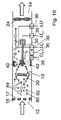
- FIG. 10 schematically shows the gas and particle flow through the measuring cell 10 and illustrates the operation of the impactor 20.
- the gas and particle flow generated by the fan 24 is indicated by the arrows.
- gas is sucked through the inlet opening 12, which leaves the measuring cell 10 in the right-hand area of the figure through the outlet opening 14 again.
- nanoparticles or aerosols 80, 82, 84 are carried along, which can be positively or negatively charged or electrically neutral.
- the positively charged nanoparticles are identified by the reference numeral 80, the negatively charged nanoparticles by the reference numeral 82 and the neutral nanoparticles by the reference numeral 84,
- a flow around the impactor 20 occurs around the impactor 20 in the gas flow.
- the metal contacts 36 can be seen, on which the electrophoresis voltage U EP , the electrothermal excitation voltage u ET , the supply voltage U 0 and the output voltage ⁇ U of the Wheatstone bridge are applied.
- the electrophoresis voltage U ESP is negative, so that positively charged nanoparticles 80 are deposited on the vibrating beam 30.
- the neutral particles 84 and the negatively charged particles 82 are predominantly not in contact with the vibrating bars 30 and leave the measuring cell 10 through the outlet opening 14.
- the deposited nanoparticles 80 influence the resonant frequency of the vibrating beam 30.
- a control loop is controlled, which adjusts the excitation voltage u akt to the current resonant frequency.
- the temporal course of the resonance frequency is recorded and further processed.
Landscapes
- Chemical & Material Sciences (AREA)
- General Physics & Mathematics (AREA)
- Physics & Mathematics (AREA)
- Biochemistry (AREA)
- Life Sciences & Earth Sciences (AREA)
- Analytical Chemistry (AREA)
- Health & Medical Sciences (AREA)
- General Health & Medical Sciences (AREA)
- Immunology (AREA)
- Pathology (AREA)
- Dispersion Chemistry (AREA)
- Sampling And Sample Adjustment (AREA)
- Other Investigation Or Analysis Of Materials By Electrical Means (AREA)
Abstract
Description
- Die Erfindung betrifft ein Gerät zur Messung einer Aerosolkonzentration in einem gasförmigen Medium, umfassend
- a. eine Messzelle mit einem Gehäuse mit einer Eintrittsöffnung und einer Austrittsöffnung,
- b. einen Schwingbalken, der zu Schwingungen angeregt werden kann,
- c. eine Anregungsvorrichtung, um den Schwingbalken zu Schwingungen anzuregen,
- d. eine Vorrichtung zum Erzeugen eines Gasstroms des gasförmigen Mediums durch das Messgerät und
- e. eine Messeinrichtung zum Ermitteln einer Resonanzfrequenz des Schwingbalkens.
- Die Erfindung betrifft weiterhin ein Verfahren zur Messung einer Aerosolkonzentration in einem gasförmigen Medium, mit den Schritten:
- i. Anregen eines Schwingbalkens zu Schwingungen mit einer Resonanzfrequenz des Schwingbalkens
- ii. Abscheiden von in dem gasförmigen Medium vorhandenen Aerosolen auf einem Schwingbalken
- iii. Zeitaufgelöstes Ermitteln der jeweiligen momentanen Resonanzfrequenz des Schwingbalkens
- iv. Weiterverarbeiten der ermittelten Resonanzfrequenzen.
- Die Nanotechnologie ist ein schnell wachsender Bereich der Wissenschaft und der Industrie. Nanopartikel, also Teilchen mit einer Größe von typischerweise 1 bis 1000 Nanometern, finden sich heute bereits in einer Vielzahl von Anwendungen. So werden Nanopartikel oder Nanotechnologie im Allgemeinen z.B, in der Elektronik, in Bildschirmen, für Batterien, Kraftfahrzeuge, Luft- und Raumfahrt oder im Gesundheitswesen eingesetzt.
- Zusätzlich zu den natürlich in der Umgebungsluft vorkommenden Nanopartikeln, die z.B. durch Erosion oder als Pilzsporen in die Luft gelangen, sind mit den genannten Anwendungen auch eine Vielzahl von Quellen von künstlich hergestellten Nanopartikeln entstanden. Es hat sich gezeigt, dass Teilchen mit einer Partikelgröße von unter 100 Nanometern potentiell gesundheitsschädlich sein können bzw. dass ihre toxischen Effekte bei gleicher aufgenommener Masse diejenigen von größeren Partikeln übersteigen können. Eine Aufnahme ist für den Menschen dabei besonders einfach mit der eingeatmeten Luft über die Lunge möglich. Dabei können sich negative Effekte direkt auf die Lunge oder auf andere Systeme des Körpers ergeben, da die Nanopartikel im menschlichen Körper durch ihre Größe bedingt eine hohe Mobilität zeigen.
- Neben der allgemeinen Feinstaub-Konzentration in der Luft ist es daher besonders wünschenswert, Geräte zur Überwachung der Arbeitsbedingungen von Menschen, die in der Produktion von Nanopartikeln oder an anderen Stellen, wo solche Nanopartikel als Nebenprodukt in die Luft gelangen können, tätig sind.
- Elemente eines gattungsgemäßen Geräts zur Messung einer Aerosolkonzentration sind beispielsweise aus dem Artikel von H.S. Wasisto et al. "Portable cantilever-based airborne nanoparticle detector", veröffentlicht in Sensors and Actuators B 187 (2013), 118-127, bekannt. Der Artikel beschreibt eine Messzelle mit einer Eintrittsöffnung und einer Austrittsöffnung, in der ein aus Silizium gefertigter Schwingbalken oder Cantilever, angeordnet ist. Der Schwingbalken wird mittels eines piezoelektrischen Elements zu Schwingungen angeregt, indem eine sinusförmige Spannung an das piezoelektrische Element angelegt wird. Über eine in den Schwingbalken integrierte piezoresistive Wheatstone-Brücke kann die erzeugte Schwingung ausgelesen und so die Resonanzfrequenz bestimmt werden. Da die Resonanzfrequenz des Schwingbalkens von seiner Masse abhängt, wird diese durch die Anlagerung von Nanopartikeln beeinflusst. Durch ein an den Schwingbalken angelegtes Potential erfahren geladene Nanopartikel eine zum Schwingbalken hin gerichtete Kraft, lagern sich auf diesem ab und beeinflussen so seine Resonanzfrequenz. Die Veränderung der Resonanzfrequenz über einen bestimmten Zeitraum kann also als Maß für die im gleichen Zeitraum angelagerten Nanopartikel dienen. Mittelbar lassen sich so Rückschlüsse auf die Nanopartikelkonzentration in der Umgebungsluft ziehen.
- Es hat sich herausgestellt, dass die Anhaftung der Nanopartikel auf dem Schwingbalken bei dem beschriebenen System mangelhaft ist und somit die Effizienz und Genauigkeit des Messgeräts negativ beeinflusst. Ein Teil der angelagerten Teilchen löst sich noch während des Messprozesses wieder vom Schwingbalken, so dass die Messung verfälscht wird. Weiterhin haben beim beschriebenen System auch größere Teilchen Zugang zum Schwingbalken, so dass auch aus diesem Grund Verfälschungen der Messung der Konzentration von Nanopartikeln entstehen können.
- Es ist daher die Aufgabe der vorliegenden Erfindung, ein hochgenaues, kompaktes und möglichst kostengünstig herzustellendes Gerät zur Messung einer Aerosolkonzentration bereitzustellen, das eine Anhaftung einer möglichst großen Menge von Nanopartikeln an dem Schwingbalken ermöglicht.
- Die Erfindung löst das Problem durch ein gattungsgemäßes Gerät zur Messung einer Aerosolkonzentration in einem gasförmigen Medium, dessen Anregungsvorrichtung ein elektrothermisches Element umfasst, welches den Schwingbalken zu Schwingungen anregt, wenn eine oszillierende Spannung an das elektrothermische Element angelegt wird. Der Wechselspannung kann ein Gleichanteil überlagert sein.
- Das Problem wird weiterhin gelöst durch ein gattungsgemäßes Verfahren zur Messung einer Aerosolkonzentration in einem gasförmigen Medium, bei dem der Schwingbalken mittels eines elektrothermischen Elements angeregt wird.
- Es wird erfindungsgemäß also kein piezoelektrisches Element, sondern ein elektrothermisches Element, z.B. ein Heizwiderstand, zur Anregung des Schwingbalkens genutzt. Es hat sich gezeigt, dass auf diese Art und Weise ein definierter Bereich des Schwingbalkens, in dem sich die Nanopartikel anlagern sowie eine geringere Neigung am Schwingbalken haftender Nanopartikel, sich wieder vom Schwingbalken zu lösen, erreicht werden kann. Durch die elektrothermische Anregung des Schwingbalkens lässt sich mit hohem Gütefaktor eine Biegeschwingung in-plane, also in einer Ebene mit der Abscheidefläche der Nanopartikel erreichen. "Out-of-plane" bezeichnet entsprechend die Schwingungsrichtung, die senkrecht zur Ebene der Abscheidefläche steht. Aufgrund eines nicht quadratischen Querschnitts mit einem Breite-zu-Höhe-Verhältnis von z,B, etwa 5 kann die Auslenkung in-plane etwa um den Faktor 25 geringer als out-of-plane sein. Eine möglichst geringe Bewegung im Schwingbalken ist wünschenswert, um Fliehkräfte auf die anhaftenden Nanopartikel zu minimieren und damit eine mögliche Ablösung zu verhindern.
- Zur Anregung des Schwingbalkens wird dabei eine Spannung an das elektrothermische Element oder an die elektrothermischen Elemente angelegt, so dass ein elektrischer Strom fließt. Dieser führt zu einer erhöhten Temperatur im Bereich des jeweiligen elektrothermischen Elements und so zu einer entsprechenden räumlichen Ausdehnung. Da das elektrothermische Element eine räumliche Inhomogenität des Schwingbalkens darstellt, kommt es zu einer Formveränderung des Schwingbalkens in Gestalt einer Biegung. Durch geeignete Ausgestaltung des elektrothermischen Elements bzw. der elektrothermischen Elemente kann der Schwingbalken so in Kombination mit der oszillierenden Spannung bzw. mit dem oszillierenden Strom kontrolliert zu einer Schwingung angeregt werden. Die Schwingungsfrequenz entspricht dabei der Frequenz, mit der die Spannung/der Strom oszilliert. Eine oszillierende Spannung bedeutet hierbei eine periodisch veränderte Spannung, die z.B. eine sinusförmige, eine dreieckförmige oder eine rechteckförmige Spannung sein kann, Bevorzugt kann die oszillierende Spannung derart ausgestaltet sein, dass periodisch ein Potential angelegt und wieder ausgeschaltet wird, so dass sich Perioden von Stromfluss und entsprechender Erwärmung mit Perioden ohne Stromfluss und somit einer Abkühlung des elektrothermischen Elements abwechseln.
- Die in jeder Periode erreichten Temperaturdifferenzen können dabei im Bereich von einigen °C liegen. Ein Schwingbalken aus Silizium mit einer Größe von z.B. 1.000 µm x 170 µm x 15-20 µm (Länge x Breite x Dicke) hat typischerweise eine Resonanzfrequenz im Bereich von 200 kHz. Größere Schwingbalken sind ebenso wie noch kleiner Abmessungen möglich. Für einen Schwingbalken mit Abmessungen von z.B. 2.750 µm x 100 µm x 50 µm liegt die Resonanzfrequenz z.B. im Bereich von etwa 10 kHz. Durch geeignete Positionierung der elektrothermischen Elemente z.B. nahe der Einspannstelle des Schwingbalkens und somit in der Nähe massiver Teile wie z.B. eines Einbaurahmes kann eine schnelle Ableitungsmöglichkeit der eingebrachten Wärme ermöglicht werden, so dass eine elektrothermische Anregung auch mit hohen Frequenzen im Bereich von z.B. 1 kHz bis zu 500 kHz möglich ist.
- Prinzipiell ist es möglich, ausschließlich Nanopartikel zu detektieren, die lediglich aufgrund ihrer thermischen Bewegung auf den Schwingbalken treffen und sich dort ablagern. Da aber eine hohe relative Ausbeute der vorhandenen Nanopartikel wünschenswert ist, um die Genauigkeit der Messung zu erhöhen, ist es sinnvoll, die Nanopartikel zum Schwingbalken hin zu leiten.
- Dies kann zum einen dadurch geschehen, dass an den Schwingbalken mittels einer Spannungsquelle eine im Wesentlichen konstante Potentialdifferenz von zumindest 200 V gegenüber Erdpotential angelegt wird. Da im Normalfall ein Teil der als Aerosol vorliegenden Nanopartikel eine elektrische Ladung aufweist, kann durch das so erzeugte elektrische Feld mittels Elektrophorese eine auf den Schwingbalken hin gerichtete Kraft auf diese Nanopartikel ausgeübt werden, so dass diese sich bevorzugt am Schwingbalken anlagern. Eine höhere Potentialdifferenz von z.B. zumindest 500 V vergrößert die ausgeübte Kraft und somit die Ausbeute an Nanopartikeln. Wird ein negatives Potential angelegt, so werden positiv geladene Nanopartikel angelagert und umgekehrt. Durchschnittlich sind gleich viele positiv geladene wie negativ geladene Nanopartikel in der Luft vorhanden, so dass im Allgemeinen kein Vorzeichen des angelegten Potentials bevorzugt ist. Alternativ kann durch eine vorgeschaltete Ladestufe der Ladungszustand des analysierten Aerosols eingestellt werden.
- Eine weitere Möglichkeit, die Nanopartikel in Richtung des Schwingbalkens zu transportieren ist die Thermophorese. Dabei kann ein Heizelement, das auf eine Temperatur von zumindest 100 °C, bevorzugt von zumindest 400 °C aufgeheizt werden kann, zur Erzeugung eines negativen Temperaturgradienten in Richtung des Schwingbalkens eingesetzt werden. Ein negativer Temperaturgradient in Richtung des Schwingbalkens bedeutet dabei, dass die unmittelbare Umgebungstemperatur des Schwingbalkens niedriger ist als die äußeren Bereiche des Temperaturfeldes. So kann in der Messzelle z.B. umlaufend um den Schwingbalken ein Heizelement angebracht werden, um einen entsprechenden Temperaturgradienten herzustellen z.B. durch eine Heizspule, die symmetrisch um den Schwingbalken herum angeordnet ist. Hierbei ist es entscheidend, den Heizvorgang nicht kontinuierlich, sondern gepulst, z.B. zwischen z.B, 410 °C und 35 °C mit Heiz- und Abkühlzeiten von z.B, etwa 1 min zu betreiben. Bei "abgeschaltetem" Temperaturgradienten können Nanopartikel in die Zone unmittelbar um den Schwingbalken herum gelangen, um dann bei "eingeschaltetem" Temperaturgradienten anschließend auf den Schwingbalken hingetrieben zu werden.
- Die Thermophorese hat den Vorteil, dass sie nicht auf eine elektrische Ladung der zu detektierenden Teilchen angewiesen ist. Zum Einfangen der zu detektierenden Nanopartikel können auch beide Methoden kombiniert werden. Außerdem werden mit Thermophorese bevorzugt sehr kleine Nanopartikel mit Durchmessern kleiner als 20 nm erfasst.
- Um die Ausbeute an am Schwingbalken angelagerten Partikeln zu erhöhen, umfasst das Gerät weiterhin eine Vorrichtung zum Erzeugen eines Gasstroms des gasförmigen Mediums durch das Messgerät. Es wird so kontinuierlich Umgebungsluft zu- und abgeführt. Durch die zwangsläufig entstehenden Turbulenzen kommen mehr Nanopartikel mit dem Schwingbalken in Kontakt, so dass die Ausbeute weiter erhöht wird. Bei der Vorrichtung zum Erzeugen eines Gasstroms kann es sich um einen Ventilator handeln, der Vorteile aufgrund seiner kompakten Bauweise aufweist. Der Einsatz z.B. einer Pumpe ist aber ebenso denkbar.
- Eine Weiterbildung der Erfindung sieht vor, dass der Schwingbalken aus einem dotierten Halbleitermaterial besteht und auf zumindest einer Oberfläche des Schwingbalkens eine Fläche ausgebildet ist, die eine höhere Dotierung als ein Grundkörper des Schwingbalkens aufweist, so dass sich bei einem an dieser Fläche anliegenden negativen bzw. positiven Potential Aerosole bevorzugt auf dieser abscheiden. Zu diesem Zweck kann beispielsweise eine Elektrode aus p-dotiertem Material vorgesehen werden, während das Grundmaterial des Schwingbalkens aus n-dotiertem Material, beispielsweise aus n-dotiertem Silizium, besteht. Ein solcher Schwingbalken ist dann ausgelegt, um positiv oder negativ geladene Teilchen einzusammeln, so dass für die Elektrophorese ein negatives bzw. positives Potential an den Schwingbalken angelegt werden muss. Es hat sich herausgestellt, dass mit einer entsprechenden Dotierung eine verbesserte Haftung der Teilchen auf dem Schwingbalken und eine genauer definierte Abscheidefläche erreicht werden kann Da Feldüberhöhungen an Ecken und Kanten hierbei nicht auftreten, erfolgt die Partikelabscheidung eher flächig gleichmäßig verteilt und nicht bevorzugt an Ecken und Kanten: Es bilden sich keine kettenartigen Agglomerate aus, die sich aufgrund ihrer Trägheit leicht wieder ablösen, sondern an vielen Stellen am Schwingbalken haftende Lagen von Einzelpartikeln.
- Durch Abscheiden von Teilchen, die größer als die zu detektierenden Nanopartikel sind, kann es zu deutlichen Verfälschungen der Messung kommen. Es ist daher sinnvoll, Vorkehrungen zu treffen, dass nur eine möglichst geringe Menge von solchen größeren Teilchen auf den Schwingbalken trifft. Eine Möglichkeit, größere Teilchen vom Schwingbalken fernzuhalten, ist der Einsatz eines Filters an der Eintrittsöffnung der Messzelle. Die größeren Teilchen oder Teilchenagglomerate werden so am Eindringen in die Messzelle gehindert. Ein solcher Filter kann eine Porengröße von beispielsweise 5 µm aufweisen. Bevorzugt weist der Filter eine Porengröße von maximal 2,5 µm auf. Es kann sich dabei z,B. um einen Mikrofilter handeln, der aus einer Siliziummembran mit geätzten Löchern besteht. Die Membrandicke und damit die Höhe der Lochwand kann mit z.B. 12 µm so gering sein, dass eine Anlagerung kleiner Partikel, z.B. durch Diffusionsabscheidung aus dem durchströmenden Luftvolumen vernachlässigt werden kann. Es wird so erreicht, dass einerseits nur die zu detektierenden Nanopartikel Einfluss auf die Resonanzfrequenz des Schwingbalkens nehmen und andererseits, dass sich die Messzelle nicht verschmutzt und mit größeren Teilchen zugesetzt wird.
- Eine weitere Möglichkeit, um möglichst keine Teilchen einer nicht gewünschten Größenordnung zu detektieren, besteht darin, zwischen der Eintrittsöffnung und dem Schwingbalken einen Impaktor anzuordnen. Ein sogenannter Impaktor ist dabei eine einfache, ggf. kreisförmige Platte, die zentral im Gas- bzw. Luftstrom zwischen der Eintrittsöffnung und dem Schwingbalken angeordnet ist. Um den Impaktor herum bildet sich eine Strömung aus, die bevorzugt leichtere Teilchen, also hauptsächlich die zu detektierenden Nanopartikel, mit sich reißt. Größere Teilchen prallen aufgrund ihrer größeren Massenträgheit auf den Impaktor und werden dort abgelagert. Sie sind somit aus dem Gasstrom entfernt und können nicht mehr bis zum Schwingbalken gelangen. Bevorzugt ist der Abstand des Impaktors zur Eintrittsöffnung variabel, so dass das Messgerät an verschiedene Umgebungsbedingungen wie z.B. unterschiedliche zu detektierende Partikelgrößen oder -materialien wie künstliche Nanopartikel am Arbeitsplatz oder Rußpartikel im Straßenverkehr angepasst werden kann.
- Die Ausbeute an angelagerten Nanopartikeln kann weiter erhöht werden, wenn die Oberfläche des Schwingbalkens eine Nanostrukturierung aufweist. Diese kann z.B. aus auf der Oberfläche des Schwingbalkens angeordneten Nanosäulen mit Durchmessern von typischerweise 300 nm, Höhen von 1 bis 2 µm in einem Rastermaß von typischerweise 500 nm bestehen. Die Herstellung auf dem Schwingbalken ist beispielsweise durch eine Kombination von Nano-Imprint-Lithographie zur Strukturierung der Nanosäulen und Photolithographie zur Strukturierung der Schwingbalken möglich. Es kann dabei entweder zuerst der Photolithographie-Prozess und anschließend der Nano-Imprint-Prozess oder bevorzugt zuerst der Nano-Imprint-Prozess und dann anschließend der Photolithographie-Prozess durchgeführt werden. Durch die deutlich vergrößerte Oberfläche kommen mehr Partikel mit dem Schwingbalken in Berührung und können sich auf diesem anlagern.
- Die Messeinrichtung zum Ermitteln der Resonanzfrequenz des Schwingbalkens kann eine Wheatstone-Brücke umfassen. Diese kann integral mit dem Schwingbalken ausgeführt sein. Die Wheatstone-Brücke umfasst ein piezoresistives Element, das in Abhängigkeit des Biegezustands des Schwingbalkens eine Ausgangsspannung liefert. Wenn eine konstante Spannung an die Wheatstone-Brücke angelegt wird, liefert die Wheatstone-Brücke an ihrem Ausgang aufgrund ihres sich in Abhängigkeit vom Biegezustand des Schwingbalkens ändernden elektrischen Widerstands ein mit der aktuellen Schwingungsfrequenz des Schwingbalkens oszillierendes Signal, so dass die Frequenz der Schwingung gemessen werden kann, Über geeignete Mess- bzw. Regelmechanismen kann dann die aktuelle Resonanzfrequenz f0 und deren Änderung Δf0 in einem Zeitintervall Δt bestimmt werden Aus Δf0/Δt kann dann mittels einer geeigneten Kalibrierung die Aerosolkonzentration im Umgebungsmedium bestimmt werden. Die Messung von Δf0/Δt erfolgt zyklisch im Wechsel mit der elektrophoretischen bzw. thermophoretischen Partikelsammlung: Während der Messung ist die Sammelspannung abgeschaltet und während der Partikelsammlung ist die Schwingungserregung abgeschaltet.
- Eine Ausgestaltungsmöglichkeit für einen solchen Regelmechanismus kann darin bestehen, dass die Messeinrichtung zum Ermitteln der Resonanzfrequenz des Schwingbalkens eine Phasenregelschleife (engl. Phase Locked Loop, PLL) umfasst. Mit Hilfe der Wheatstone-Brücke kann die Amplitude der Schwingung des Schwingbalkens zeitaufgelöst bestimmt werden. Die Anregungsfrequenz kann geändert werden, bis die Amplitude ein Maximum aufweist. Dann ist die aktuelle Resonanzfrequenz eingestellt. Es kann so die Resonanzfrequenz des Schwingbalkens nachverfolgt sowie ihre Verschiebung aufgezeichnet werden. Die Phasenregelschleife besteht im Wesentlichen aus einem Phasendetektor, einem Schleifenfilter und einem spannungsgeregelten Oszillator. Eine Unterstützungselektronik kann aus einem Vorverstärker zur Signalverstärkung am Resonatorausgang bestehen. Durch einen solchen Regelmechanismus kann auch die Frequenz, mit der der Schwingbalken angeregt wird, auf die aktuelle Resonanzfrequenz des Schwingbalkens abgestimmt werden.
- Die Anregungsvorrichtung kann wie die Wheatstone-Brücke integral mit dem Schwingbalken ausgeführt sein. Der Schwingbalken ist dann ein selbsterregender, selbstdetektierender Resonator oder Cantilever.
- Weitere Bauteile zur Vervollständigung des Messgeräts können ein Energieverteilungsnetzwerk mit einem Hochspannungs-Modul, ein tragbares Gehäuse im Handheld-Format sowie ein Mikrokontroller und Display sein. Ein solcher Prototyp wurde von den Erfindern bereits produziert und getestet. Somit wurde erstmals ein äußerst kompaktes, hochgenaues, einfach zu handhabendes und energiesparendes Gerät zur Messung einer Aerosolkonzerltration in der Umgebungsluft hergestellt.
- Das Gerät kann z.B. durch drei handelsübliche 1,5V-Batterien oder Akkus mit Strom versorgt werden Das Energieverteilungsnetzwerk versorgt die Anregungseinheit, den Mikrokontroller und das Display mit Strom und beinhaltet weiterhin ein Hochspannungsmodul, das die Elektrophorese-Einheit speist. Die Hochspannung für die Elektrophorese-Einheit kann dabei z.B. im Bereich von 230 V bis 930 V regelbar sein Durch niedrige Leistungsaufnahmen von z.B. 0,04 W bis 0,28 W ergibt sich eine lange Laufzeit des Geräts.
- Ein Mikrokontroller kann die Daten aus dem Frequenzmesssystem, z.B. also aus der Phasenregelschleife aufnehmen, weiterverarbeiten und in eine für den Endnutzer sinnvolle Darstellung bringen. Es kann also z.B. die gemessene Frequenzverschiebung des Schwingbalkens, auf dem sich Nanopartikel abgelagert haben, gegenüber der Resonanzfrequenz des "nackten" Schwingbalkens sowie die berechnete Massenkonzentration von Nanopartikeln in der Umgebungsluft angezeigt werden. Weitere Auswertungen, z.B. eine graphische Darstellung der gemessenen Massenkonzentration in Abhängigkeit von der Zeit, sind ebenfalls denkbar und vorgesehen.
- Durch das kompakte Gehäuse ist ein Wechsel der Energiequelle leicht möglich. Ebenso kann der Schwingbalken vom Anwender selbst ausgetauscht werden, wenn dieser z.B. ohne weitere Befestigungsmittel reversibel in das Messgerät eingesteckt wird. Federbelastete Kontaktspitzen können dann sowohl für die elektrische Kontaktierung als auch für eine mechanische Befestigung sorgen.
- Die Schwingbalken können wiederverwendet werden, wenn sie entsprechend gesäubert worden sind. Dies ist beispielsweise trocken mit einem Strom von gasförmigem Stickstoff oder in einem Nassverfahren möglich. Einfach durchzuführen ist dabei eine Reinigung in einem Ultraschallbad, beispielsweise mit Aceton oder deionisiertem Wasser als flüssigem Medium. Ebenfalls denkbar ist ein Schwingbalken, der eine dünne Opferschicht aufweist, die bei der Reinigung dann zusammen mit den darauf haftenden Nanopartikeln entfernt wird.
- Im Folgenden wird die Erfindung anhand der beigefügten Figuren näher erläutert. Dabei zeigt:
- Figur 1
- eine schematische Seitenansicht eines erfindungsgemäßen Geräts zur Messung einer Aerosolkonzentration;
- Figur 2
- eine schematische Draufsicht auf das Gerät gemäß
Figur 1 ; - Figur 3
- eine Schemazeichnung eines Mikrofilters;
- Figur 4
- eine Schemazeichnung eines Impaktors;
- Figur 5
- eine schematische Darstellung eines erfindungsgemäßen Schwingbalkens in Draufsicht;
- Figur 6
- eine schematische Darstellung eines erfindungsgemäßen Schwingbalkens in Seitenansicht;
- Figur 7
- eine schematische Seitenansicht eines nanostrukturierten Schwingbalkens;
- Figur 8
- eine Rückansicht eines erfindungsgemäßen Geräts mit einer möglichen Anordnung der Hauptschaltkreise;
- Figur 9
- eine schematische Vorderansicht eines erfindungsgemäßen Geräts; sowie
- Figur 10
- eine schematische Darstellung des Gas- und Partikelstroms während eines Messvorgangs.
- Anhand der
Figuren 1 bis 4 soll zunächst das Grundprinzip des Messverfahrens und des Messgeräts erläutert werden, bevor dann auf die spezielle elektrothermische Anregung eingegangen wird.Figur 1 zeigt ein Ausführungsbeispiel eines erfindungsgemäßen Geräts zur Messung einer Aerosolkonzentration. Die Messzelle 10 wird von dem zu untersuchenden Gas durchströmt. Das Gas tritt durch die Eintrittsöffnung 12 ein und durch die Austrittsöffnung 14 aus der Messzelle aus. Der Ventilator 24 sorgt dabei für einen kontinuierlichen Gasstrom durch die Messzelle 10 Innerhalb der Messzelle ist der Schwingbalken 30 angeordnet. Die von dem Gasstrom mitgeführten Aerosole bzw. Nanopartikel lagern sich zumindest teilweise auf dem Schwingbalken 30 ab. Die dadurch veränderte Masse des Schwingbalkens 30 beeinflusst seine Resonanzfrequenz. Um zu verhindern, dass unerwünschte vergleichsweise große Partikel in die Messzelle 10 gelangen, ist an der Eintrittsöffnung 12 der Partikelfilter 16 angeordnet, der die Einlassöffnung 12 teilweise verschließt. Der Partikelfilter 16 überdeckt mit seinem Querschnitt den Querschnitt der Eintrittsöffnung 12 und weist Öffnungen auf, die in der Größenordnung der größten Teilchen, die detektiert werden sollen, liegt. Größere Teilchen werden durch den Partikelfilter bzw. Mikrofilter 16 am Eindringen in die Messzelle 10 gehindert. - Als weitere Maßnahme zum Verhindern der Anlagerung zu großer Teilchen am Schwingbalken 30 ist zwischen dem Schwingbalken 30 und der Einlassöffnung 12 ein Impaktor 20 angeordnet. Dieser ist so positioniert, dass er den kürzesten Weg von der Einlassöffnung 12 zum Schwingbalken 30 blockiert. Es entsteht daher ein Gasstrom um den Impaktor 20 herum. Leichtere und somit kleinere Teilchen werden von dem Gasstrom mit um den Impaktor 20 herum geführt, wohingegen größere und somit schwerere Teilchen gegen den Impaktor 20 prallen, dort abgelagert oder "impaktiert" werden und somit aus dem Gasstrom entfernt werden.
- Eine Gegenelektrode 40 ist auf mehreren Seiten des Schwingbalkens 30 angeordnet. Sie kann um den Schwingbalken 30 umlaufend und zum Beispiel ringförmig ausgeführt sein. Die Gegenelektrode 40 kann durch Anlegen eines elektrischen Potenzials dazu genutzt werden, um mittels Elektrophorese eine in Richtung des Schwingbalkens 30 gerichtete Kraft auf die zu detektierenden Teilchen auszuüben. Ebenfalls kann durch ein gegebenenfalls periodisches Erhitzen der Gegenelektrode 40 ein Temperaturgradient innerhalb der Messzelle 10 erzeugt werden, der aufgrund von Thermophorese ebenfalls zu einer Ablagerung der zu detektierenden Teilchen auf dem Schwingbalken 30 führt.
- Eine Abgrenzung 26 trennt den Sensormontagebereich vom Partikelsammler. Die Messzelle 10 weist weiterhin federbelastete Kontaktstifte 31 auf, die den Schwingbalken 30 sowohl fixieren als auch elektrisch kontaktieren. Es ist so ein einfaches Wechseln des Schwingbalkens 30 ohne aufwendige Löt-, Schraub- oder sonstige Fixiermaßnahmen möglich. Die Kontaktstifte 31 gehen in Stifte 32 über, mit denen eine Verbindung zum Gehäuse 60 hergestellt werden kann. Auf der Oberseite des Gehäuses 60 sind ein LCD-Display 62 und ein Ein-/Aus-Schalter 64 vorhanden. Im Gehäuse selbst sind ein Hochspannungs-Modul 68, eine Batterie 70 sowie verschiedene Mess-, Regel- und Speicherschaltkreise 66 vorhanden.
-
Figur 2 zeigt eine Draufsicht auf das Gerät gemäßFigur 1 . Neben dem Gehäuse 60 mit dem LCD-Display 62 und dem Ein-/Aus-Schalter 64 ist die Messzelle 10 mit dem Mikrofilter 16, dem Impaktor 20, der Gegenelektrode 40, dem Schwingbalken 30, den federbelasteten Kontaktstiften 31 sowie dem Ventilator 24 zu erkennen. Die Abgrenzung 26 trennt auch hier den Sensormontagebereich vom Partikelsammler. -
Figur 3 zeigt eine schematische Darstellung eines Mikrofilters 16. Der Mikrofilter 16 besteht aus einem Filterrahmen 19, der eine Siliziummembran 18 trägt, welche eine Dicke von 12 µm aufweist. In die Siliziummembran 18 sind Löcher 17 geätzt. Die Löcher 17 weisen einen Durchmesser von 2,5 µm auf. Die Darstellung ist nicht maßstabsgerecht. -
Figur 4 zeigt einen Impaktor 20, der mittels des Impaktorhalters 21 im Impaktorrahmen 22 befestigt ist. im zusammengefügten Zustand des erfindungsgemäßen Geräts befindet sich der Schwingbalken 30 in Stromrichtung des Gasstroms zentral hinter dem Impaktor 20. Ein Teilchen, das sich auf dem Schwingbalken anlagert, muss somit im radial äußeren Bereich der Messzelle 10 den Impaktor 20 passieren und danach eine Bewegung nach innen auf den Schwingbalken 30 zu ausführen. Dies ist umso wahrscheinlicher, je kleiner und somit auch leichter die Teilchen sind. Größere Teilchen prallen mit hoher Wahrscheinlichkeit gegen den Impaktor 20 und werden so aus dem Gasstrom entfernt, oder verlassen die Messzelle durch die Austrittsöffnung wieder. -
Figur 5 zeigt eine vergrößerte Darstellung eines erfindungsgemäßen Schwingbalkens bzw. Cantilevers 30. Im linken Bereich der Figur ist die p-leitende Nanopartikel-Sammelfläche 38 zu sehen, an der sich die Nanopartikel ablagern. Rechts ist der aus Silizium bestehende Montagerahmen 39 zur Befestigung des Schwingbalkens 30 und zur Aufnahme der Kontakte zu sehen. Der rechte Bereich des Schwingbalkens 30 ist als n-leitender Bereich 37 ausgeführt. In diesem n-leitendem Bereich 37 befinden sich eine p-leitende, U-förmige piezoresistive Wheatstonesche Brücke 52 sowie zwei p-leitende Heizwiderstände 34. Im Messbetrieb werden die Heizwiderstände 34 mit einer oszillierenden Spannung beaufschlagt, so dass ein entsprechender Strom durch die Widerstände 34 fließt. Die Widerstände 34 dehnen sich periodisch aus und der Schwingbalken 30 wird in Schwingungen versetzt. Mittels der Wheatstoneschen Brücke 52 kann die aktuelle Frequenz ausgelesen werden. Mittels eines geeigneten Regelmechanismus kann dann die Resonanzfrequenz ermittelt werden, -
Figur 6 zeigt eine seitliche Schnittansicht des Schwingbalkens 30 gemäßFigur 5 . Auch hier ist zu erkennen, dass der Schwingbalken 30 zum größten Teil aus n-leitendem Silizium 37 aufgebaut ist. Neben dem Montagerahmen 39, den Heizwiderständen 34 und der Wheatstoneschen Brücke 52 ist hier zu erkennen, dass auf dem Schwingbalken 30 Metallkontakte 36, die aus Chrom und Gold bestehen, aufgebracht sind. Jeweils unter diesen elektrischen Kontakten 36 sind p+-dotierte Bereiche zur Herstellung der ohmschen Kontakte vorhanden. - Die Heizwiderstände 34 sind aus p-leitendem Silizium hergestellt. Es wird so ein den Stromfluss sperrender p/n-Übergang zwischen dem Bereich des Heizwiderstands 34 und dem n-leitenden Grundkörper 37 des Schwingbalkens 30 erzeugt. Es ist dadurch möglich, einen Strom durch ausgewählte Bereiche des Schwingbalkens 30, in diesem Fall also durch die Heizwiderstände 34, zu leiten, so dass sich lediglich diese Bereiche erwärmen. Die Heizwiderstände 34, die hier die elektrothermischen Elemente darstellen, sind oberflächennah angeordnet. Eine Ausdehnung der Heizwiderstände 34 kann daher auch zur Anregung einer vertikalen Resonanzschwingung mit einer Verbiegung des Schwingbalkens 30 nach unten führen.
- Mit alternativen Designs der Heizwiderstände 34 und/oder einer angepassten Ansteuerung kann die Schwingungsrichtung beeinflusst werden. So können z.B. die in
Figur 5 gezeigten beiden Heizwiderstände 34 abwechselnd mit Strom versorgt werden, so dass dann eine Schwingung angeregt wird, die in der Darstellung gemäßFigur 5 vertikal verläuft und entsprechend der Darstellung gemäßFigur 6 senkrecht zur Papierebene steht. Um eine solche Schwingung noch effizienter anzuregen, können die Positionen der Heizwiderstände 34 innerhalb des Schwingbalkens 30 angepasst werden, also z.B. oberflächenferner ausgestaltet werden. Die verwendeten Ströme liegen dabei z.B. im Bereich von einigen mA und die eingebrachte Wärmeleistung im Bereich von einigen mW. -
Figur 7 zeigt einen der Darstellung inFigur 6 entsprechenden Schwingbalken 30, dessen Oberfläche jedoch nanostrukturiert ist, um den zu detektierenden Teilchen eine größere Fläche zur Verfügung zu stellen. Im gezeigten Beispiel besteht die Sammelfläche 38 aus einem Silizium-Nanosäulen-Array. -
Figur 8 zeigt eine Draufsicht auf die Platine, die die Hauptschaltkreise 66 gemäßFigur 1 beherbergt. Im Einzelnen sind dies die phasenregelschleifenbasierte Frequenznachführung (PLL) 54, ein Mikrocontroller 56, eine Speichereinheit, die in diesem Fall als SD-Speicherkarte 58 ausgeführt ist, ein Hochspannungsmodul 68 sowie das Leistungsverteilnetzwerk 72. - Die
Figur 9 zeigt die Platine gemäßFigur 8 in der Vorderansicht. Zu erkennen ist hier das LCD-Display 62 sowie verschiedene Steckanschlüsse 74 zum Anschluss des elektrostatischen bzw. thermophoretischen Partikelsammlers. -
Figur 10 zeigt schematisch den Gas- und Partikelstrom durch die Messzelle 10 und veranschaulicht die Wirkungsweise des Impaktors 20. Der durch den Ventilator 24 erzeugte Gas- und Partikelstrom ist durch die Pfeile angedeutet. Im linken Bereich der Figur wird durch die Eintrittsöffnung 12 Gas angesaugt, welches die Messzelle 10 im rechten Bereich der Figur durch die Austrittsöffnung 14 wieder verlässt. Im Gasstrom werden Nanopartikel bzw. Aerosole 80, 82, 84 mitgeführt, die positiv oder negativ geladen oder elektrisch neutral sein können. Die positiv geladenen Nanopartikel sind mit dem Bezugszeichen 80, die negativ geladenen Nanopartikel mit dem Bezugszeichen 82 und die neutralen Nanopartikel mit dem Bezugszeichen 84 gekennzeichnet, - Augrund des sich im Gasstrom befindlichen Impaktors 20 erfolgt eine Strömung um den Impaktor 20 herum. Je kleiner die Teilchen 80, 82, 84 sind, umso größer ist die Wahrscheinlichkeit, dass die Teilchen 80, 82, 84 dem Gasstrom um den Impaktor 20 herum folgen. Größere Teilchen 80, 82, 84 treffen mit höherer Wahrscheinlichkeit auf den Impaktor 20 und werden so aus dem Gasstrom entfernt. Da sich der Schwingbalken 30 im "Windschatten" des Impaktors 20 befindet, müssen die Nanopartikel 80, 82, 84, hinter dem Impaktor 20 eine Bewegung nach axial innen ausführen, um zum Schwingbalken 30 zu gelangen. Auch diese Bewegung tritt mit größerer Wahrscheinlichkeit für kleinere Teilchen 80, 82, 84 auf, so dass auch dieser Effekt die Größenselektion der detektierten Teilchen verstärkt.
- In
Figur 10 sind weiterhin die Metallkontakte 36 zu sehen, an denen die Elektrophoresespannung UEP, die elektrothermische Anregungsspannung uET, die Speisespannung U0 und die Ausgangsspannung ΔU der Wheatstone-Brücke angelegt werden. Im gezeigten Beispiel ist die Elektrophoresespannung UESP negativ, so dass positiv geladene Nanopartikel 80 auf dem Schwingbalken 30 abgelagert werden. Die neutralen Teilchen 84 und die negativ geladenen Teilchen 82 kommen überwiegend nicht mit den Schwingbalken 30 in Kontakt und verlassen die Messzelle 10 durch die Austrittsöffnung 14. - Die angelagerten Nanopartikel 80 beeinflussen die Resonanzfrequenz des Schwingbalkens 30. Mittels der Messspannung usens wird ein Regelkreis gesteuert, der die Anregungsspannung uakt auf die aktuelle Resonanzfrequenz einstellt. Der zeitliche Verlauf der Resonanzfrequenz wird aufgezeichnet und weiterverarbeitet.
-
10 Messzelle 52 Wheatstonesche Brücke 12 Eintrittsöffnung 54 PLL 14 Austrittsöffnung 56 Mikrocontroller 16 Partikelfilter 58 SD-Speicherkarte 17 Löcher 18 Siliziummembran 60 Gehäuse 19 Filterrahmen 62 LCD-Display 64 Schalter 20 Impaktor 66 Hauptschaltkreise 21 Impaktorhalter 68 Hochspannungsmodul 22 Impaktorrahmen 24 Ventilator 70 Batterie 26 Abgrenzung 72 Leistungsverteilnetzwerk 74 Steckanschlüsse 30 Schwingbalken 31 Kontaktstifte 80 positives Teilchen 32 Stifte 82 negatives Teilchen 34 Heizwiderstand 84 neutrales Teilchen 36 Metallkontakte 37 n-leitendes Silizium 38 Sammelfläche 39 Montagerahmen 40 Gegenelektrode/Heizelement
Claims (10)
- Gerät zur Messung einer Aerosolkonzentration in einem gasförmigen Medium, umfassendi. eine Messzelle (10) mit einem Gehäuse (60) mit einer Eintrittsöffnung (12) und einer Austrittsöffnung (14),ii. einen Schwingbalken (30), der zu Schwingungen angeregt werden kann,iii. eine Anregungsvorrichtung (34), um den Schwingbalken (30) zu Schwingungen anzuregen,iv. eine Vorrichtung zum Erzeugen eines Gasstroms (24) des gasförmigen Mediums durch das Messgerät undv. eine Messeinrichtung (52) zum Ermitteln einer Resonanzfrequenz des Schwingbalkens (30),
dadurch gekennzeichnet, dassvi. die Anregungsvorrichtung ein elektrothermisches Element (34) umfasst, welches den Schwingbalken (30) zu Schwingungen anregt, wenn eine oszillierende Spannung an das elektrothermische Element (34) angelegt wird. - Gerät nach Anspruch 1, gekennzeichnet durch eine Spannungsquelle, die eingerichtet ist, um an den Schwingbalken (30) eine im Wesentlichen konstante Potentialdifferenz von zumindest 200 V, bevorzugt von zumindest 500 V gegenüber dem Gehäuse (60) der Messzelle (10) anzulegen.
- Gerät nach Anspruch 1 oder 2, dadurch gekennzeichnet, dass es ein Heizelement (40) zur Erzeugung eines negativen Temperaturgradienten in Richtung des Schwingbalkens (30) umfasst.
- Gerät nach einem der vorstehenden Ansprüche, dadurch gekennzeichnet, dass der Schwingbalken (30) aus einem dotierten Halbleitermaterial besteht und auf zumindest einer Oberfläche (38) des Schwingbalkens (30) eine Fläche ausgebildet ist, die eine höhere Dotierung als ein Grundkörper des Schwingbalkens (30) aufweist.
- Gerät nach einem der vorstehenden Ansprüche, dadurch gekennzeichnet, dass ein Filter (16) mit einer Porengröße von höchstens 5 µm, bevorzugt von höchstens 2,5 µm vor der Eintrittsöffnung (12) der Messzelle (10) angeordnet ist, so dass größere Teilchen am Eindringen in die Messzelle (10) gehindert werden.
- Gerät nach einem der vorstehenden Ansprüche, dadurch gekennzeichnet, dass zwischen der Eintrittsöffnung (12) und dem Schwingbalken (30) ein Impaktor (20) angeordnet ist.
- Gerät nach einem der vorstehenden Ansprüche, dadurch gekennzeichnet, dass die Oberfläche (39) des Schwingbalkens (30) eine Nanostrukturierung aufweist.
- Gerät nach einem der vorstehenden Ansprüche, dadurch gekennzeichnet, dass die Messeinrichtung zum Ermitteln der Resonanzfrequenz des Schwingbalkens (30) eine Wheatstone-Brücke (52) umfasst.
- Gerät nach einem der vorstehenden Ansprüche, dadurch gekennzeichnet, dass die Messeinrichtung zum Ermitteln der Resonanzfrequenz des Schwingbalkens (30) eine Phasenregelschleife (54) umfasst.
- Verfahren zur Messung einer Aerosolkonzentration in einem gasförmigen Medium, mit den Schritten:i. Anregen eines Schwingbalkens (30) zu Schwingungen mit einer Resonanzfrequenz des Schwingbalkens (30),ii. Abscheiden von in dem gasförmigen Medium vorhandenen Aerosolen (80, 82) auf dem Schwingbalken (30),iii. zeitaufgelöstes Ermitteln der jeweiligen momentanen Resonanzfrequenz des Schwingbalkens (30),iv. Weiterverarbeiten der ermittelten Resonanzfrequenzen,
dadurch gekennzeichnet, dassv. der Schwingbalken (30) mittels eines elektrothermischen Elements (34) angeregt wird
Applications Claiming Priority (1)
| Application Number | Priority Date | Filing Date | Title |
|---|---|---|---|
| DE102014007977.5A DE102014007977A1 (de) | 2014-06-04 | 2014-06-04 | Gerät und Verfahren zur Messung einer Aerosolkonzentration in einem gasförmigen Medium |
Publications (2)
| Publication Number | Publication Date |
|---|---|
| EP2952875A1 true EP2952875A1 (de) | 2015-12-09 |
| EP2952875B1 EP2952875B1 (de) | 2020-08-05 |
Family
ID=53397755
Family Applications (1)
| Application Number | Title | Priority Date | Filing Date |
|---|---|---|---|
| EP15001651.7A Active EP2952875B1 (de) | 2014-06-04 | 2015-06-03 | Gerät und verfahren zur messung einer aerosolkonzentration in einem gasförmigen medium |
Country Status (2)
| Country | Link |
|---|---|
| EP (1) | EP2952875B1 (de) |
| DE (1) | DE102014007977A1 (de) |
Cited By (2)
| Publication number | Priority date | Publication date | Assignee | Title |
|---|---|---|---|---|
| WO2019099570A1 (en) * | 2017-11-14 | 2019-05-23 | Aerodyne Microsystems Inc., a Delaware Corporation | Thermophoretic particle concentrator |
| US10705053B2 (en) | 2018-01-19 | 2020-07-07 | National Tsing Hua University | Thermal-piezoresistive oscillator-based aerosol sensor and aerosol sensing method |
Citations (4)
| Publication number | Priority date | Publication date | Assignee | Title |
|---|---|---|---|---|
| US3614677A (en) * | 1966-04-29 | 1971-10-19 | Ibm | Electromechanical monolithic resonator |
| US20130036793A1 (en) * | 2011-08-08 | 2013-02-14 | University Of California | Microfabricated particulate matter monitor |
| WO2013064157A1 (en) * | 2011-11-04 | 2013-05-10 | Danmarks Tekniske Universitet | Resonant fiber based aerosol particle sensor and method |
| US20130133441A1 (en) * | 2011-05-24 | 2013-05-30 | Rj Lee Group | Thermophoretic sampler |
Family Cites Families (2)
| Publication number | Priority date | Publication date | Assignee | Title |
|---|---|---|---|---|
| US7578973B2 (en) * | 1998-11-13 | 2009-08-25 | Mesosystems Technology, Inc. | Devices for continuous sampling of airborne particles using a regenerative surface |
| US8718956B2 (en) * | 2010-09-29 | 2014-05-06 | Phillip 66 Company | High-pressure quartz crystal microbalance |
-
2014
- 2014-06-04 DE DE102014007977.5A patent/DE102014007977A1/de not_active Withdrawn
-
2015
- 2015-06-03 EP EP15001651.7A patent/EP2952875B1/de active Active
Patent Citations (4)
| Publication number | Priority date | Publication date | Assignee | Title |
|---|---|---|---|---|
| US3614677A (en) * | 1966-04-29 | 1971-10-19 | Ibm | Electromechanical monolithic resonator |
| US20130133441A1 (en) * | 2011-05-24 | 2013-05-30 | Rj Lee Group | Thermophoretic sampler |
| US20130036793A1 (en) * | 2011-08-08 | 2013-02-14 | University Of California | Microfabricated particulate matter monitor |
| WO2013064157A1 (en) * | 2011-11-04 | 2013-05-10 | Danmarks Tekniske Universitet | Resonant fiber based aerosol particle sensor and method |
Non-Patent Citations (4)
| Title |
|---|
| ARASH HAJJAM ET AL: "Fabrication and characterization of thermally actuated micromechanical resonators for airborne particle mass sensing: II. Device fabrication and characterization;Fabrication and characterization of thermally actuated micromechanical resonators for airborne particle mass sensing: II", JOURNAL OF MICROMECHANICS & MICROENGINEERING, INSTITUTE OF PHYSICS PUBLISHING, BRISTOL, GB, vol. 20, no. 12, 18 November 2010 (2010-11-18), pages 125019, XP020201642, ISSN: 0960-1317, DOI: 10.1088/0960-1317/20/12/125019 * |
| ARASH HAJJAM ET AL: "Individual Air-Borne Particle Mass Measurement Using High-Frequency Micromechanical Resonators", IEEE SENSORS JOURNAL, IEEE SERVICE CENTER, NEW YORK, NY, US, vol. 11, no. 11, 1 November 2011 (2011-11-01), pages 2883 - 2890, XP011358381, ISSN: 1530-437X, DOI: 10.1109/JSEN.2011.2147301 * |
| H.S. WASISTO ET AL.: "Portable cantilever-based airborne nanoparticl'e detector", VERÖFFENTLICHT IN SENSORS AND ACTUATORS B, vol. 187, 2013, pages 118 - 127, XP028705834, DOI: doi:10.1016/j.snb.2012.09.074 |
| WASISTO HUTOMO SURYO ET AL: "Portable cantilever-based airborne nanoparticle detector", SENSORS AND ACTUATORS B: CHEMICAL: INTERNATIONAL JOURNAL DEVOTED TO RESEARCH AND DEVELOPMENT OF PHYSICAL AND CHEMICAL TRANSDUCERS, vol. 187, 22 September 2012 (2012-09-22), pages 118 - 127, XP028705834, ISSN: 0925-4005, DOI: 10.1016/J.SNB.2012.09.074 * |
Cited By (2)
| Publication number | Priority date | Publication date | Assignee | Title |
|---|---|---|---|---|
| WO2019099570A1 (en) * | 2017-11-14 | 2019-05-23 | Aerodyne Microsystems Inc., a Delaware Corporation | Thermophoretic particle concentrator |
| US10705053B2 (en) | 2018-01-19 | 2020-07-07 | National Tsing Hua University | Thermal-piezoresistive oscillator-based aerosol sensor and aerosol sensing method |
Also Published As
| Publication number | Publication date |
|---|---|
| EP2952875B1 (de) | 2020-08-05 |
| DE102014007977A1 (de) | 2015-12-17 |
Similar Documents
| Publication | Publication Date | Title |
|---|---|---|
| US8806915B2 (en) | Microfabricated particulate matter monitor | |
| DE112006001351B4 (de) | Instrumente zum Messen der Belastung durch Nanopartikel | |
| US7437908B2 (en) | Particle counter | |
| US11326991B2 (en) | Airborne particle detection with selective thermophoretic particle deflection | |
| DE69300790T2 (de) | Verschmutzungsdetektor für Luftfilter. | |
| US3413545A (en) | Apparatus and method for determining aerosol particle concentration and particle size distribution | |
| EP0386665A2 (de) | Verfahren zur Messung von Partikeln in polydispersen Systemen und von Partikelkonzentrationen monodisperser Aerosole sowie Messvorrichtung zur Durchführung des Verfahrens | |
| Barlow et al. | A laboratory study of the scavenging of sub‐micron aerosol by charged raindrops | |
| WO2015146456A1 (ja) | 微粒子の個数計測器及び微粒子の個数計測方法 | |
| Vu et al. | Enhanced electrohydrodynamics for electrospinning a highly sensitive flexible fiber-based piezoelectric sensor | |
| DE2517533C3 (de) | Strömungsmesser mit einem Wirbel erzeugenden Element | |
| EP2952875B1 (de) | Gerät und verfahren zur messung einer aerosolkonzentration in einem gasförmigen medium | |
| EP2330400A2 (de) | Partikelmessgerät, insbesondere zur Analyse von Korngrössen feiner und feinster Schüttgüter | |
| CN107847945A (zh) | 用于选择性纯化气溶胶的方法 | |
| EP1525449A1 (de) | Impedanzmessung in einem fluidischen mikrosystem | |
| EP2741079B1 (de) | Porositätsmessvorrichtung und porositätsmessverfahren | |
| DE112005000255T5 (de) | Verstärkerschaltung eines integrierenden Elektrometers | |
| EP3596445A1 (de) | Partikelsensor und verfahren zur messung von partikelkonzentrationen | |
| US20210109005A1 (en) | Particle matter analysis device, analysis method and manufacturing method thereof | |
| DE102012211538B4 (de) | Verfahren und System zum Nachweisen von in einem Aerosol schwebenden Kohlenstoffnanoröhren | |
| Robert et al. | Acoustic separation of sub-micron particles in gases | |
| DE102005011402A1 (de) | Thermischer Massenflussmesser für Gase und Verfahren zur Bestimmung des Massenflusses eines Gases | |
| DE102016108964B4 (de) | Vorrichtung und Verfahren zur Bestimmung des Stoffmengenanteils von Gaskomponenten einer diskreten Probe eines mehrkomponentigen Gasgemischs | |
| AT514855A1 (de) | Vorrichtung zur Fraktionierung von in einer Flüssigkeit enthaltenen Partikeln | |
| EP1744831A1 (de) | Verfahren und vorrichtung zur sammlung von suspendierten partikeln |
Legal Events
| Date | Code | Title | Description |
|---|---|---|---|
| PUAI | Public reference made under article 153(3) epc to a published international application that has entered the european phase |
Free format text: ORIGINAL CODE: 0009012 |
|
| AK | Designated contracting states |
Kind code of ref document: A1 Designated state(s): AL AT BE BG CH CY CZ DE DK EE ES FI FR GB GR HR HU IE IS IT LI LT LU LV MC MK MT NL NO PL PT RO RS SE SI SK SM TR |
|
| AX | Request for extension of the european patent |
Extension state: BA ME |
|
| 17P | Request for examination filed |
Effective date: 20160530 |
|
| RBV | Designated contracting states (corrected) |
Designated state(s): AL AT BE BG CH CY CZ DE DK EE ES FI FR GB GR HR HU IE IS IT LI LT LU LV MC MK MT NL NO PL PT RO RS SE SI SK SM TR |
|
| STAA | Information on the status of an ep patent application or granted ep patent |
Free format text: STATUS: EXAMINATION IS IN PROGRESS |
|
| 17Q | First examination report despatched |
Effective date: 20171107 |
|
| RAP1 | Party data changed (applicant data changed or rights of an application transferred) |
Owner name: FRAUNHOFER-GESELLSCHAFT ZUR FOERDERUNG DER ANGEWAN |
|
| RIC1 | Information provided on ipc code assigned before grant |
Ipc: G01N 15/00 20060101ALN20200109BHEP Ipc: G01N 15/06 20060101AFI20200109BHEP Ipc: G01G 3/16 20060101ALI20200109BHEP Ipc: G01N 5/02 20060101ALI20200109BHEP Ipc: G01N 1/22 20060101ALN20200109BHEP |
|
| GRAP | Despatch of communication of intention to grant a patent |
Free format text: ORIGINAL CODE: EPIDOSNIGR1 |
|
| STAA | Information on the status of an ep patent application or granted ep patent |
Free format text: STATUS: GRANT OF PATENT IS INTENDED |
|
| INTG | Intention to grant announced |
Effective date: 20200214 |
|
| GRAS | Grant fee paid |
Free format text: ORIGINAL CODE: EPIDOSNIGR3 |
|
| GRAA | (expected) grant |
Free format text: ORIGINAL CODE: 0009210 |
|
| STAA | Information on the status of an ep patent application or granted ep patent |
Free format text: STATUS: THE PATENT HAS BEEN GRANTED |
|
| AK | Designated contracting states |
Kind code of ref document: B1 Designated state(s): AL AT BE BG CH CY CZ DE DK EE ES FI FR GB GR HR HU IE IS IT LI LT LU LV MC MK MT NL NO PL PT RO RS SE SI SK SM TR |
|
| REG | Reference to a national code |
Ref country code: GB Ref legal event code: FG4D Free format text: NOT ENGLISH |
|
| REG | Reference to a national code |
Ref country code: CH Ref legal event code: EP |
|
| REG | Reference to a national code |
Ref country code: AT Ref legal event code: REF Ref document number: 1299388 Country of ref document: AT Kind code of ref document: T Effective date: 20200815 |
|
| REG | Reference to a national code |
Ref country code: DE Ref legal event code: R096 Ref document number: 502015013143 Country of ref document: DE |
|
| REG | Reference to a national code |
Ref country code: IE Ref legal event code: FG4D Free format text: LANGUAGE OF EP DOCUMENT: GERMAN |
|
| REG | Reference to a national code |
Ref country code: NL Ref legal event code: FP |
|
| REG | Reference to a national code |
Ref country code: LT Ref legal event code: MG4D |
|
| PG25 | Lapsed in a contracting state [announced via postgrant information from national office to epo] |
Ref country code: GR Free format text: LAPSE BECAUSE OF FAILURE TO SUBMIT A TRANSLATION OF THE DESCRIPTION OR TO PAY THE FEE WITHIN THE PRESCRIBED TIME-LIMIT Effective date: 20201106 Ref country code: NO Free format text: LAPSE BECAUSE OF FAILURE TO SUBMIT A TRANSLATION OF THE DESCRIPTION OR TO PAY THE FEE WITHIN THE PRESCRIBED TIME-LIMIT Effective date: 20201105 Ref country code: ES Free format text: LAPSE BECAUSE OF FAILURE TO SUBMIT A TRANSLATION OF THE DESCRIPTION OR TO PAY THE FEE WITHIN THE PRESCRIBED TIME-LIMIT Effective date: 20200805 Ref country code: PT Free format text: LAPSE BECAUSE OF FAILURE TO SUBMIT A TRANSLATION OF THE DESCRIPTION OR TO PAY THE FEE WITHIN THE PRESCRIBED TIME-LIMIT Effective date: 20201207 Ref country code: LT Free format text: LAPSE BECAUSE OF FAILURE TO SUBMIT A TRANSLATION OF THE DESCRIPTION OR TO PAY THE FEE WITHIN THE PRESCRIBED TIME-LIMIT Effective date: 20200805 Ref country code: BG Free format text: LAPSE BECAUSE OF FAILURE TO SUBMIT A TRANSLATION OF THE DESCRIPTION OR TO PAY THE FEE WITHIN THE PRESCRIBED TIME-LIMIT Effective date: 20201105 Ref country code: FI Free format text: LAPSE BECAUSE OF FAILURE TO SUBMIT A TRANSLATION OF THE DESCRIPTION OR TO PAY THE FEE WITHIN THE PRESCRIBED TIME-LIMIT Effective date: 20200805 Ref country code: HR Free format text: LAPSE BECAUSE OF FAILURE TO SUBMIT A TRANSLATION OF THE DESCRIPTION OR TO PAY THE FEE WITHIN THE PRESCRIBED TIME-LIMIT Effective date: 20200805 Ref country code: SE Free format text: LAPSE BECAUSE OF FAILURE TO SUBMIT A TRANSLATION OF THE DESCRIPTION OR TO PAY THE FEE WITHIN THE PRESCRIBED TIME-LIMIT Effective date: 20200805 |
|
| PG25 | Lapsed in a contracting state [announced via postgrant information from national office to epo] |
Ref country code: RS Free format text: LAPSE BECAUSE OF FAILURE TO SUBMIT A TRANSLATION OF THE DESCRIPTION OR TO PAY THE FEE WITHIN THE PRESCRIBED TIME-LIMIT Effective date: 20200805 Ref country code: LV Free format text: LAPSE BECAUSE OF FAILURE TO SUBMIT A TRANSLATION OF THE DESCRIPTION OR TO PAY THE FEE WITHIN THE PRESCRIBED TIME-LIMIT Effective date: 20200805 Ref country code: PL Free format text: LAPSE BECAUSE OF FAILURE TO SUBMIT A TRANSLATION OF THE DESCRIPTION OR TO PAY THE FEE WITHIN THE PRESCRIBED TIME-LIMIT Effective date: 20200805 Ref country code: IS Free format text: LAPSE BECAUSE OF FAILURE TO SUBMIT A TRANSLATION OF THE DESCRIPTION OR TO PAY THE FEE WITHIN THE PRESCRIBED TIME-LIMIT Effective date: 20201205 |
|
| PG25 | Lapsed in a contracting state [announced via postgrant information from national office to epo] |
Ref country code: SM Free format text: LAPSE BECAUSE OF FAILURE TO SUBMIT A TRANSLATION OF THE DESCRIPTION OR TO PAY THE FEE WITHIN THE PRESCRIBED TIME-LIMIT Effective date: 20200805 Ref country code: RO Free format text: LAPSE BECAUSE OF FAILURE TO SUBMIT A TRANSLATION OF THE DESCRIPTION OR TO PAY THE FEE WITHIN THE PRESCRIBED TIME-LIMIT Effective date: 20200805 Ref country code: EE Free format text: LAPSE BECAUSE OF FAILURE TO SUBMIT A TRANSLATION OF THE DESCRIPTION OR TO PAY THE FEE WITHIN THE PRESCRIBED TIME-LIMIT Effective date: 20200805 Ref country code: DK Free format text: LAPSE BECAUSE OF FAILURE TO SUBMIT A TRANSLATION OF THE DESCRIPTION OR TO PAY THE FEE WITHIN THE PRESCRIBED TIME-LIMIT Effective date: 20200805 Ref country code: CZ Free format text: LAPSE BECAUSE OF FAILURE TO SUBMIT A TRANSLATION OF THE DESCRIPTION OR TO PAY THE FEE WITHIN THE PRESCRIBED TIME-LIMIT Effective date: 20200805 |
|
| REG | Reference to a national code |
Ref country code: DE Ref legal event code: R097 Ref document number: 502015013143 Country of ref document: DE |
|
| PG25 | Lapsed in a contracting state [announced via postgrant information from national office to epo] |
Ref country code: AL Free format text: LAPSE BECAUSE OF FAILURE TO SUBMIT A TRANSLATION OF THE DESCRIPTION OR TO PAY THE FEE WITHIN THE PRESCRIBED TIME-LIMIT Effective date: 20200805 |
|
| PLBE | No opposition filed within time limit |
Free format text: ORIGINAL CODE: 0009261 |
|
| STAA | Information on the status of an ep patent application or granted ep patent |
Free format text: STATUS: NO OPPOSITION FILED WITHIN TIME LIMIT |
|
| PG25 | Lapsed in a contracting state [announced via postgrant information from national office to epo] |
Ref country code: SK Free format text: LAPSE BECAUSE OF FAILURE TO SUBMIT A TRANSLATION OF THE DESCRIPTION OR TO PAY THE FEE WITHIN THE PRESCRIBED TIME-LIMIT Effective date: 20200805 |
|
| 26N | No opposition filed |
Effective date: 20210507 |
|
| PG25 | Lapsed in a contracting state [announced via postgrant information from national office to epo] |
Ref country code: IT Free format text: LAPSE BECAUSE OF FAILURE TO SUBMIT A TRANSLATION OF THE DESCRIPTION OR TO PAY THE FEE WITHIN THE PRESCRIBED TIME-LIMIT Effective date: 20200805 |
|
| PG25 | Lapsed in a contracting state [announced via postgrant information from national office to epo] |
Ref country code: SI Free format text: LAPSE BECAUSE OF FAILURE TO SUBMIT A TRANSLATION OF THE DESCRIPTION OR TO PAY THE FEE WITHIN THE PRESCRIBED TIME-LIMIT Effective date: 20200805 |
|
| PG25 | Lapsed in a contracting state [announced via postgrant information from national office to epo] |
Ref country code: MC Free format text: LAPSE BECAUSE OF FAILURE TO SUBMIT A TRANSLATION OF THE DESCRIPTION OR TO PAY THE FEE WITHIN THE PRESCRIBED TIME-LIMIT Effective date: 20200805 |
|
| REG | Reference to a national code |
Ref country code: CH Ref legal event code: PL |
|
| REG | Reference to a national code |
Ref country code: BE Ref legal event code: MM Effective date: 20210630 |
|
| PG25 | Lapsed in a contracting state [announced via postgrant information from national office to epo] |
Ref country code: LU Free format text: LAPSE BECAUSE OF NON-PAYMENT OF DUE FEES Effective date: 20210603 |
|
| PG25 | Lapsed in a contracting state [announced via postgrant information from national office to epo] |
Ref country code: LI Free format text: LAPSE BECAUSE OF NON-PAYMENT OF DUE FEES Effective date: 20210630 Ref country code: IE Free format text: LAPSE BECAUSE OF NON-PAYMENT OF DUE FEES Effective date: 20210603 Ref country code: CH Free format text: LAPSE BECAUSE OF NON-PAYMENT OF DUE FEES Effective date: 20210630 |
|
| PG25 | Lapsed in a contracting state [announced via postgrant information from national office to epo] |
Ref country code: FR Free format text: LAPSE BECAUSE OF NON-PAYMENT OF DUE FEES Effective date: 20210630 |
|
| PG25 | Lapsed in a contracting state [announced via postgrant information from national office to epo] |
Ref country code: BE Free format text: LAPSE BECAUSE OF NON-PAYMENT OF DUE FEES Effective date: 20210630 |
|
| REG | Reference to a national code |
Ref country code: AT Ref legal event code: MM01 Ref document number: 1299388 Country of ref document: AT Kind code of ref document: T Effective date: 20210603 |
|
| PG25 | Lapsed in a contracting state [announced via postgrant information from national office to epo] |
Ref country code: AT Free format text: LAPSE BECAUSE OF NON-PAYMENT OF DUE FEES Effective date: 20210603 |
|
| PG25 | Lapsed in a contracting state [announced via postgrant information from national office to epo] |
Ref country code: HU Free format text: LAPSE BECAUSE OF FAILURE TO SUBMIT A TRANSLATION OF THE DESCRIPTION OR TO PAY THE FEE WITHIN THE PRESCRIBED TIME-LIMIT; INVALID AB INITIO Effective date: 20150603 |
|
| P01 | Opt-out of the competence of the unified patent court (upc) registered |
Effective date: 20230524 |
|
| PG25 | Lapsed in a contracting state [announced via postgrant information from national office to epo] |
Ref country code: CY Free format text: LAPSE BECAUSE OF FAILURE TO SUBMIT A TRANSLATION OF THE DESCRIPTION OR TO PAY THE FEE WITHIN THE PRESCRIBED TIME-LIMIT Effective date: 20200805 |
|
| PG25 | Lapsed in a contracting state [announced via postgrant information from national office to epo] |
Ref country code: MK Free format text: LAPSE BECAUSE OF FAILURE TO SUBMIT A TRANSLATION OF THE DESCRIPTION OR TO PAY THE FEE WITHIN THE PRESCRIBED TIME-LIMIT Effective date: 20200805 |
|
| PG25 | Lapsed in a contracting state [announced via postgrant information from national office to epo] |
Ref country code: TR Free format text: LAPSE BECAUSE OF FAILURE TO SUBMIT A TRANSLATION OF THE DESCRIPTION OR TO PAY THE FEE WITHIN THE PRESCRIBED TIME-LIMIT Effective date: 20200805 |
|
| PG25 | Lapsed in a contracting state [announced via postgrant information from national office to epo] |
Ref country code: MT Free format text: LAPSE BECAUSE OF FAILURE TO SUBMIT A TRANSLATION OF THE DESCRIPTION OR TO PAY THE FEE WITHIN THE PRESCRIBED TIME-LIMIT Effective date: 20200805 |
|
| PGFP | Annual fee paid to national office [announced via postgrant information from national office to epo] |
Ref country code: DE Payment date: 20250618 Year of fee payment: 11 |
|
| PGFP | Annual fee paid to national office [announced via postgrant information from national office to epo] |
Ref country code: GB Payment date: 20250620 Year of fee payment: 11 |
|
| PGFP | Annual fee paid to national office [announced via postgrant information from national office to epo] |
Ref country code: NL Payment date: 20250618 Year of fee payment: 11 |