EP2952729A1 - Exhaust gas recirculation control device and exhaust gas recirculation control method for internal combustion engine - Google Patents
Exhaust gas recirculation control device and exhaust gas recirculation control method for internal combustion engine Download PDFInfo
- Publication number
- EP2952729A1 EP2952729A1 EP13874107.9A EP13874107A EP2952729A1 EP 2952729 A1 EP2952729 A1 EP 2952729A1 EP 13874107 A EP13874107 A EP 13874107A EP 2952729 A1 EP2952729 A1 EP 2952729A1
- Authority
- EP
- European Patent Office
- Prior art keywords
- egr
- control valve
- opening degree
- internal combustion
- combustion engine
- Prior art date
- Legal status (The legal status is an assumption and is not a legal conclusion. Google has not performed a legal analysis and makes no representation as to the accuracy of the status listed.)
- Granted
Links
Images

Classifications
-
- F—MECHANICAL ENGINEERING; LIGHTING; HEATING; WEAPONS; BLASTING
- F02—COMBUSTION ENGINES; HOT-GAS OR COMBUSTION-PRODUCT ENGINE PLANTS
- F02M—SUPPLYING COMBUSTION ENGINES IN GENERAL WITH COMBUSTIBLE MIXTURES OR CONSTITUENTS THEREOF
- F02M26/00—Engine-pertinent apparatus for adding exhaust gases to combustion-air, main fuel or fuel-air mixture, e.g. by exhaust gas recirculation [EGR] systems
- F02M26/02—EGR systems specially adapted for supercharged engines
- F02M26/04—EGR systems specially adapted for supercharged engines with a single turbocharger
- F02M26/06—Low pressure loops, i.e. wherein recirculated exhaust gas is taken out from the exhaust downstream of the turbocharger turbine and reintroduced into the intake system upstream of the compressor
-
- F—MECHANICAL ENGINEERING; LIGHTING; HEATING; WEAPONS; BLASTING
- F02—COMBUSTION ENGINES; HOT-GAS OR COMBUSTION-PRODUCT ENGINE PLANTS
- F02B—INTERNAL-COMBUSTION PISTON ENGINES; COMBUSTION ENGINES IN GENERAL
- F02B37/00—Engines characterised by provision of pumps driven at least for part of the time by exhaust
- F02B37/12—Control of the pumps
- F02B37/16—Control of the pumps by bypassing charging air
-
- F—MECHANICAL ENGINEERING; LIGHTING; HEATING; WEAPONS; BLASTING
- F02—COMBUSTION ENGINES; HOT-GAS OR COMBUSTION-PRODUCT ENGINE PLANTS
- F02D—CONTROLLING COMBUSTION ENGINES
- F02D21/00—Controlling engines characterised by their being supplied with non-airborne oxygen or other non-fuel gas
- F02D21/06—Controlling engines characterised by their being supplied with non-airborne oxygen or other non-fuel gas peculiar to engines having other non-fuel gas added to combustion air
- F02D21/08—Controlling engines characterised by their being supplied with non-airborne oxygen or other non-fuel gas peculiar to engines having other non-fuel gas added to combustion air the other gas being the exhaust gas of engine
-
- F—MECHANICAL ENGINEERING; LIGHTING; HEATING; WEAPONS; BLASTING
- F02—COMBUSTION ENGINES; HOT-GAS OR COMBUSTION-PRODUCT ENGINE PLANTS
- F02D—CONTROLLING COMBUSTION ENGINES
- F02D41/00—Electrical control of supply of combustible mixture or its constituents
- F02D41/0025—Controlling engines characterised by use of non-liquid fuels, pluralities of fuels, or non-fuel substances added to the combustible mixtures
- F02D41/0047—Controlling exhaust gas recirculation [EGR]
- F02D41/0077—Control of the EGR valve or actuator, e.g. duty cycle, closed loop control of position
-
- F—MECHANICAL ENGINEERING; LIGHTING; HEATING; WEAPONS; BLASTING
- F02—COMBUSTION ENGINES; HOT-GAS OR COMBUSTION-PRODUCT ENGINE PLANTS
- F02M—SUPPLYING COMBUSTION ENGINES IN GENERAL WITH COMBUSTIBLE MIXTURES OR CONSTITUENTS THEREOF
- F02M26/00—Engine-pertinent apparatus for adding exhaust gases to combustion-air, main fuel or fuel-air mixture, e.g. by exhaust gas recirculation [EGR] systems
- F02M26/13—Arrangement or layout of EGR passages, e.g. in relation to specific engine parts or for incorporation of accessories
- F02M26/22—Arrangement or layout of EGR passages, e.g. in relation to specific engine parts or for incorporation of accessories with coolers in the recirculation passage
- F02M26/23—Layout, e.g. schematics
- F02M26/28—Layout, e.g. schematics with liquid-cooled heat exchangers
-
- F—MECHANICAL ENGINEERING; LIGHTING; HEATING; WEAPONS; BLASTING
- F02—COMBUSTION ENGINES; HOT-GAS OR COMBUSTION-PRODUCT ENGINE PLANTS
- F02M—SUPPLYING COMBUSTION ENGINES IN GENERAL WITH COMBUSTIBLE MIXTURES OR CONSTITUENTS THEREOF
- F02M26/00—Engine-pertinent apparatus for adding exhaust gases to combustion-air, main fuel or fuel-air mixture, e.g. by exhaust gas recirculation [EGR] systems
- F02M26/49—Detecting, diagnosing or indicating an abnormal function of the EGR system
-
- F—MECHANICAL ENGINEERING; LIGHTING; HEATING; WEAPONS; BLASTING
- F02—COMBUSTION ENGINES; HOT-GAS OR COMBUSTION-PRODUCT ENGINE PLANTS
- F02D—CONTROLLING COMBUSTION ENGINES
- F02D41/00—Electrical control of supply of combustible mixture or its constituents
- F02D41/0002—Controlling intake air
- F02D2041/0017—Controlling intake air by simultaneous control of throttle and exhaust gas recirculation
-
- F—MECHANICAL ENGINEERING; LIGHTING; HEATING; WEAPONS; BLASTING
- F02—COMBUSTION ENGINES; HOT-GAS OR COMBUSTION-PRODUCT ENGINE PLANTS
- F02D—CONTROLLING COMBUSTION ENGINES
- F02D41/00—Electrical control of supply of combustible mixture or its constituents
- F02D41/0025—Controlling engines characterised by use of non-liquid fuels, pluralities of fuels, or non-fuel substances added to the combustible mixtures
- F02D41/0047—Controlling exhaust gas recirculation [EGR]
- F02D41/0065—Specific aspects of external EGR control
-
- Y—GENERAL TAGGING OF NEW TECHNOLOGICAL DEVELOPMENTS; GENERAL TAGGING OF CROSS-SECTIONAL TECHNOLOGIES SPANNING OVER SEVERAL SECTIONS OF THE IPC; TECHNICAL SUBJECTS COVERED BY FORMER USPC CROSS-REFERENCE ART COLLECTIONS [XRACs] AND DIGESTS
- Y02—TECHNOLOGIES OR APPLICATIONS FOR MITIGATION OR ADAPTATION AGAINST CLIMATE CHANGE
- Y02T—CLIMATE CHANGE MITIGATION TECHNOLOGIES RELATED TO TRANSPORTATION
- Y02T10/00—Road transport of goods or passengers
- Y02T10/10—Internal combustion engine [ICE] based vehicles
- Y02T10/12—Improving ICE efficiencies
-
- Y—GENERAL TAGGING OF NEW TECHNOLOGICAL DEVELOPMENTS; GENERAL TAGGING OF CROSS-SECTIONAL TECHNOLOGIES SPANNING OVER SEVERAL SECTIONS OF THE IPC; TECHNICAL SUBJECTS COVERED BY FORMER USPC CROSS-REFERENCE ART COLLECTIONS [XRACs] AND DIGESTS
- Y02—TECHNOLOGIES OR APPLICATIONS FOR MITIGATION OR ADAPTATION AGAINST CLIMATE CHANGE
- Y02T—CLIMATE CHANGE MITIGATION TECHNOLOGIES RELATED TO TRANSPORTATION
- Y02T10/00—Road transport of goods or passengers
- Y02T10/10—Internal combustion engine [ICE] based vehicles
- Y02T10/40—Engine management systems
Definitions
- the present invention relates to an exhaust gas recirculation control device and an exhaust gas recirculation control method for an internal combustion engine, for recirculating part of exhaust gas back to the upstream side of a supercharger.
- Patent document 1 discloses a technology in which a failure diagnosis for an EGR control valve, which is disposed in an EGR passage configured to connect an exhaust passage and an intake passage, is performed.
- a failure diagnosis when it is determined that an open failure, in which the EGR control valve has been fixed in its open state, is occurring, fail-safe control is executed for limiting an output of the internal combustion engine.
- Patent document 1 Japanese Patent Provisional Publication No. JP09-025852
- the invention is characterized in that, in an exhaust gas recirculation apparatus for an internal combustion engine configured to recirculate exhaust gas of an amount corresponding to a valve opening degree of an EGR control valve when an intake air amount becomes greater than a prescribed amount and to recirculate a less amount of exhaust gas regardless of the valve opening degree of the EGR control valve when the intake air amount becomes less than or equal to the prescribed amount, a limit is imposed on the intake air amount so as not to fall the internal combustion engine into a misfire state when the EGR control valve has been fixed.
- a limit on the intake air amount is imposed when it is determined that the EGR control valve has been fixed, and hence the amount of exhaust gas recirculating back to the intake system (that is, the EGR amount) reduces. Accordingly, a misfire of the internal combustion engine is prevented and thus it is possible to avoid an engine stall and also to avoid the internal combustion engine from falling into a startup disabled state.
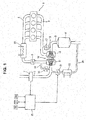
- FIG. 1 there is shown the overall system configuration of an internal combustion engine 1 to which the invention is applied.
- Internal combustion engine 1 is mounted on a vehicle, such as an automotive vehicle, as a driving power source.
- An intake passage 2 and an exhaust passage 3 are connected to the internal combustion engine.
- a throttle valve 5 is disposed in the intake passage 2, which is connected to the internal combustion engine 1 through an intake manifold 4.
- An airflow meter 7 is disposed on the upstream side of the intake passage for detecting an intake air amount.
- An exhaust catalyst 9, such as a three-way catalyst, is disposed in the exhaust passage 3, which is connected to the internal combustion engine 1 through an exhaust manifold 8, for purifying exhaust gases.
- internal combustion engine 1 has a turbo supercharger 10 equipped with a compressor 11, which is placed in the intake passage 2, and a turbine 12, which is placed in the exhaust passage 3, the compressor and the turbine being coaxially arranged.
- Compressor 11 is located on the upstream side of throttle valve 5 and also located on the downstream side of airflow meter 7.
- Turbine 12 is located on the upstream side of exhaust catalyst 9.
- reference sign 13 denotes an intercooler located on the downstream side of throttle valve 5.
- a recirculation valve 15 is disposed in the recirculation passage 14 for controlling a flow rate of intake air flowing through the recirculation passage 14.
- An exhaust bypass passage 16 which is configured to connect the upstream side and the downstream side of the turbine 12, bypassing the turbine 12, is connected to the exhaust passage 3.
- a waste gate valve 17 is disposed in the exhaust bypass passage 16 for controlling a flow rate of exhaust gas flowing through the exhaust bypass passage 16.
- EGR exhaust gas recirculation
- An EGR passage 20 is provided between the exhaust passage 3 and the intake passage 2.
- One end of EGR passage 20 is connected to the exhaust passage 3 downstream of the exhaust catalyst 9, while the other end is connected to the intake passage 2 downstream of the airflow meter 7 and upstream of the compressor 11.
- An EGR control valve 21 and an EGR cooler 22 are both disposed in the EGR passage 20.
- the valve opening degree of EGR control valve 21 is controlled by a control unit 25 for obtaining a given EGR rate which depends on an operating condition.
- Detection signals from a sensor group including a crankangle sensor 26 for detecting a crankangle of a crank shaft (not shown), an accelerator opening sensor 27 for detecting an amount of depression of an accelerator pedal (not shown), an EGR control valve opening sensor 28 for detecting a valve opening degree of EGR control valve 21 and the like, as well as a detection signal from airflow meter 7 are inputted to control unit 25.
- control unit 25 executes intake-air amount control, ignition timing control, and air/fuel ratio control of internal combustion engine 1, and also executes exhaust-gas-recirculation control (EGR control) for recirculating part of exhaust gas from the exhaust passage 3 back to the intake passage 2 by controlling the valve opening degree of EGR control valve 21 as discussed above.
- EGR control exhaust-gas-recirculation control
- respective valve openings of throttle valve 5, recirculation valve 15, and waste gate valve 17 are controlled by the control unit 25.
- a so-called check valve which is opened only when the pressure of the downstream side of compressor 11 reaches a predetermined pressure or more, may be used as the recirculation valve 15.
- the above-mentioned internal combustion engine 1 is configured to recirculate part of exhaust gas from the downstream side of turbine 12 to the upstream side of compressor 11 as EGR gas.
- an EGR rate is determined basically by the valve opening degree (the opening ratio) of EGR control valve 21.
- the EGR rate is determined only by the valve opening degree of EGR control valve 21, regardless of whether the intake air amount is large or small. Conversely when the intake air amount becomes less than or equal to the prescribed amount Qlim1 and reaches a very small amount, there is a less exhaust gas recirculated (a less EGR gas), regardless of the valve opening degree of EGR control valve 21. Hence, the EGR rate becomes approximately zero.
- Fig. 2 there is shown the correlation between the intake air amount and the EGR rate, with the valve opening degree of EGR control valve 21 adjusted to each of three different valve opening degrees (that is, large, middle, and small openings).
- the EGR rate exceeds a predetermined misfire-limit EGR rate at which internal combustion engine 1 misfires, when the intake air amount becomes greater than the prescribed amount Qliml.
- the middle valve opening degree of these three valve opening degrees in Fig. 2 and with the relatively smallest valve opening degree of these three valve opening degrees the EGR rate becomes less than the misfire-limit EGR rate in a steady state, even when the intake air amount becomes greater than the prescribed amount Qlim1.
- valve opening degree of EGR control valve 21 has been fixed to such a valve opening degree that the EGR rate becomes less than the misfire-limit EGR rate under a steady state, there is a possibility that the EGR rate temporarily becomes greater than the misfire-limit EGR rate under a transient state such as deceleration and thus the internal combustion engine 1 misfires.
- the internal combustion engine 1 tends to misfire owing to the intake air amount greater than the prescribed amount Qlim1 even in a steady state.
- the EGR rate of internal combustion engine 1 is controlled so as not to exceed the misfire-limit EGR rate even during deceleration by imposing a limit on the intake air amount and by reducing the amount of exhaust gas recirculating back to the intake passage 2 (that is, the EGR amount).
- EGR control valve 21 when EGR control valve 21 has been fixed with a valve opening degree greater than a preset valve-opening threshold value EGRVOth (details will be described later), a limit value of the intake air amount is set to the prescribed amount Qlim1 such that an upper limit of the intake air amount becomes the prescribed amount Qlim1. Conversely when EGR control valve 21 has been fixed with a valve opening degree less than or equal to the valve-opening threshold value EGRVOth, the limit value of the intake air amount is set to a prescribed amount Qlim2 (details will be described later) such that the upper limit of the intake air amount becomes the prescribed amount Qlim2.
- valve-opening threshold EGRVOth corresponds to a valve opening degree with which the EGR rate becomes the misfire-limit EGR rate in a steady state when the intake air amount becomes greater than the prescribed amount Qlim1.
- the prescribed amount Qlim1 is set to a value slightly less than such an intake air amount that the EGR rate begins to suddenly rise. This is because, strictly speaking, there is a possibility of the occurrence of an infinitesimal fluctuation in the actual intake air amount even in a steady state and hence the previously-noted setting is made to prevent the EGR rate from exceeding the misfire-limit EGR rate even when the intake air amount exceeds the prescribed amount Qliml owing to such an infinitesimal fluctuation in a steady state.
- the prescribed amount Qlim2 is set to a value greater than the prescribed amount Qlim1, and also set to decrease, as the valve opening degree of the fixing EGR control valve 21 increases.
- the prescribed amount Qlim2 is calculated, based on the valve opening degree of the fixing EGR control valve 21, from the prescribed amount Qlim2 calculation table as shown in Fig. 3 , for instance.
- the prescribed amount Qlim2 is set to decrease, as the valve opening degree of the fixing EGR control valve 21 increases, taking into account a temporary increase in EGR rate in a transient state such as deceleration. That is, when the valve opening degree of the fixing EGR control valve 21 is such a valve opening degree that the EGR rate becomes less than the misfire-limit EGR rate under a steady state, a limit on the intake air amount is alleviated depending on the valve opening degree of the fixing EGR control valve 21.
- the prescribed amount Qlim2 is set to a maximum intake air amount of internal combustion engine 1 when the valve opening degree of the fixing EGR control valve 21 is less than or equal to a first valve opening degree EGRVO1 corresponding to a predetermined minute opening degree. That is, when the valve opening degree of the fixing EGR control valve 21 is a minute opening degree, a limit on the intake air amount is not performed practically.
- the valve opening degree of the fixing EGR control valve 21 is greater than the first valve opening degree EGRVO1 and less than or equal to the valve-opening threshold value EGRVOth
- the prescribed amount Qlim2 is set to be less than the maximum intake air amount of internal combustion engine 1, and also set to decrease, as the fixed valve opening degree increases. That is, when the valve opening degree of the fixing EGR control valve 21 is greater than the first valve opening degree EGRVO1 and less than or equal to the valve-opening threshold value EGRVOth, a limit on the intake air amount is performed.
- the prescribed amount Qlim1 and the prescribed amount Qlim2 are set, taking account of different situations as discussed above. Hence, these prescribed amounts are discrete when the valve opening degree of the fixing EGR control valve 21 is the valve-opening threshold value EGRVOth.
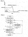
- Figs. 4-5 are two characteristic diagrams each schematically illustrating an EGR-rate change during deceleration when the limit value Qlim of the intake air amount is set to the prescribed amount Qlim2.
- FIG. 4 there is shown the characteristic diagram in a situation where the valve opening degree of the fixing EGR control valve 21 is a second valve opening degree EGRVO2 slightly greater than the first valve opening degree EGRVO1.
- the valve opening degree of the fixing EGR control valve 21 is the second valve opening degree EGRVO2
- the intake air amount (the throttle valve opening) before deceleration has not been limited so much.
- a change in the intake air amount before and after deceleration becomes large, and thus the amount of temporary increase in the deceleration-period EGR rate also becomes large.
- the initial EGR rate itself is small. Therefore, the EGR rate may not exceed the misfire-limit EGR rate.
- FIG. 5 there is shown the characteristic diagram in a situation where the valve opening degree of the fixing EGR control valve 21 is a third vale opening degree EGRVO3 closer to the valve-opening threshold value EGRVOth rather than the first valve opening degree EGRVO1.
- the valve opening degree of the fixing EGR control valve 21 is the third valve opening degree EGRV03
- the intake air amount (the throttle valve opening) before deceleration is limited by the prescribed amount Qlim2.
- a change in the intake air amount before and after deceleration becomes small, and thus the amount of temporary increase in the deceleration-period EGR rate also becomes small. Therefore, the EGR rate may not exceed the misfire-limit EGR rate.
- EGR control valve 21 when EGR control valve 21 has been fixed, it is possible to prevent a misfire of internal combustion engine 1 by imposing a limit on the intake air amount so as not to fall the internal combustion engine 1 into a misfire state even during a decelerating period. Hence, it is possible to avoid an engine stall and also to avoid the internal combustion engine 1 from falling into a startup disabled state. Additionally, even when EGR control valve 21 has been fixed, the operation of internal combustion engine 1 is possible, and thus the vehicle, whose driving power source is the internal combustion engine 1, can self-travel safely to a maintenance shop and the like, for the purpose of repairing the fixing (sticking) of EGR control valve 21.
- the system may be configured to warn or inform the driver of the fixing EGR control valve for instance by turning a warning lamp ON, when EGR control valve 21 has been fixed. Thereby, it is possible to repair the fixing EGR control valve within a maintenance shop and the like, as soon as possible.
- Fig. 6 there is shown the flowchart illustrating one example of control flow for preventing the EGR rate from exceeding the misfire-limit EGR rate even when EGR control valve 21 has been fixed.
- the control routine shown in Fig. 6 is executed within the control unit 25 as time-triggered interrupt routines to be triggered every predetermined time intervals, during operation of internal combustion engine 1.
- an engine speed Ne of internal combustion engine 1 and a valve opening degree EGRVO of EGR control valve 21 are read.
- Engine speed Ne is calculated based on an output signal from the crankangle sensor 26.
- Valve opening degree EGRVO corresponds to a valve opening degree of EGR control valve 21 detected by the previously-discussed EGR control valve opening sensor 28.
- a check is made to determine whether EGR control valve 21 is fixed. For instance, a determination of fixing of EGR control valve 21 is made such that it is determined that the EGR control valve 21 is fixed when the detected valve opening degree EGRVO diverges from a target EGR control valve opening degree and the detected valve opening degree EGRVO remains unchanged for a predetermined time.
- the routine proceeds to step S3. Conversely when EGR control valve 21 is not fixed, the current routine terminates.
- step S3 a check is made to determine whether the detected valve opening degree EGRVO of EGR control valve 21 is greater than the valve-opening threshold value EGRVOth.
- the routine proceeds to step S4. Conversely when the detected valve opening degree EGRVO is less than or equal to the valve-opening threshold value EGRVOth, the routine proceeds to step S5.
- the limit value Qlim of the intake air amount is set to the prescribed amount Qlim1. Thereby, the upper limit of the intake air amount becomes the prescribed amount Qlim1.
- the prescribed amount Qlim2 is calculated based on the detected valve opening degree EGRVO of EGR control valve 21.
- the prescribed amount Qlim2 is a value set to decrease, as the valve opening degree of the fixing EGR control valve 21 increases.
- the prescribed amount Qlim2 is calculated or retrieved from the prescribed amount Qlim2 calculation table, stored in the control unit 25, as shown in Fig. 3 .
- the routine proceeds to step S6.
- the limit value Qlim of the intake air amount is set to the prescribed amount Qlim2.
- a throttle-valve opening limit value TVOlim which brings the intake air amount to the limit value Qlim, is calculated based on the engine speed Ne and the limit value Qlim of the intake air amount, set through step S4 or step S6.
- a target throttle-valve opening degree tTVO set based on an accelerator-pedal depression amount, is compared to the throttle-valve opening limit value TVOlim, calculated through step S7.
- the target throttle-valve opening degree tTVO is greater than the throttle-valve opening limit value TVOlim, the target throttle-valve opening degree tTVO is limited by the throttle-valve opening limit value TVOlim.
- throttle valve 5 is controlled, while setting the throttle-valve opening limit value TVOlim at a target throttle opening.
Landscapes
- Engineering & Computer Science (AREA)
- Chemical & Material Sciences (AREA)
- Combustion & Propulsion (AREA)
- Mechanical Engineering (AREA)
- General Engineering & Computer Science (AREA)
- Electrical Control Of Air Or Fuel Supplied To Internal-Combustion Engine (AREA)
- Exhaust-Gas Circulating Devices (AREA)
- Combined Controls Of Internal Combustion Engines (AREA)
- Output Control And Ontrol Of Special Type Engine (AREA)
Abstract
Description
- The present invention relates to an exhaust gas recirculation control device and an exhaust gas recirculation control method for an internal combustion engine, for recirculating part of exhaust gas back to the upstream side of a supercharger.
- On internal combustion engines configured to recirculate exhaust gas, whose recirculation amount depends on an operating condition, back to the intake system, such internal combustion engines, which are configured to diagnose a failure in an EGR control valve disposed in an EGR passage for recirculating exhaust gas from the exhaust system to the intake system, are well known.
- For instance,
Patent document 1 discloses a technology in which a failure diagnosis for an EGR control valve, which is disposed in an EGR passage configured to connect an exhaust passage and an intake passage, is performed. As a result of the failure diagnosis, when it is determined that an open failure, in which the EGR control valve has been fixed in its open state, is occurring, fail-safe control is executed for limiting an output of the internal combustion engine. - In this
Patent document 1, by virtue of execution of the above-mentioned fail-safe control, it is possible to avoid high output operation of the internal combustion engine when the EGR control valve has been fixed in the open state. Hence, there is a less tendency for the EGR control valve and the intake system to be excessively heated owing to high temperature EGR gas, and thus it is possible to prevent a secondary failure in the EGR control valve and a deterioration in performance of the internal combustion engine. - However, in the
Patent document 1 there is a problem that it is impossible to prevent an engine stall, which may occur owing to a deterioration in combustion and/or a misfire caused by an excessive EGR (exhaust-gas-recirculation) rate resulting from the EGR control valve fixed or stuck in the open state. - Patent document 1: Japanese Patent Provisional Publication No.
JP09-025852 - It is, therefore, in view of the previously-described problem, the invention is characterized in that, in an exhaust gas recirculation apparatus for an internal combustion engine configured to recirculate exhaust gas of an amount corresponding to a valve opening degree of an EGR control valve when an intake air amount becomes greater than a prescribed amount and to recirculate a less amount of exhaust gas regardless of the valve opening degree of the EGR control valve when the intake air amount becomes less than or equal to the prescribed amount, a limit is imposed on the intake air amount so as not to fall the internal combustion engine into a misfire state when the EGR control valve has been fixed.
- According to the invention, a limit on the intake air amount is imposed when it is determined that the EGR control valve has been fixed, and hence the amount of exhaust gas recirculating back to the intake system (that is, the EGR amount) reduces. Accordingly, a misfire of the internal combustion engine is prevented and thus it is possible to avoid an engine stall and also to avoid the internal combustion engine from falling into a startup disabled state. Brief Description of Drawings
- [
Fig. 1] Fig. 1 is a system block diagram illustrating the overall system configuration of an internal combustion engine to which the invention is applied. - [
Fig. 2] Fig. 2 is an explanatory view schematically illustrating the correlation between an intake air amount and an EGR rate. - [
Fig. 3] Fig. 3 is a prescribed amount Qlim2 calculation table. - [
Fig. 4] Fig. 4 is a characteristic diagram schematically illustrating an EGR-rate change during deceleration when a limit value Qlim of the intake air amount is set to a prescribed amount Qlim2. - [
Fig. 5] Fig. 5 is another characteristic diagram schematically illustrating an EGR-rate change during deceleration when the limit value Qlim of the intake air amount is set to the prescribed amount Qlim2. - [
Fig. 6] Fig. 6 is a flowchart illustrating one example of control flow for preventing the EGR rate from exceeding a misfire-limit EGR rate. - The embodiments of the present invention are hereinafter described with reference to the drawings. Referring to
Fig. 1 , there is shown the overall system configuration of aninternal combustion engine 1 to which the invention is applied. -
Internal combustion engine 1 is mounted on a vehicle, such as an automotive vehicle, as a driving power source. Anintake passage 2 and anexhaust passage 3 are connected to the internal combustion engine. Athrottle valve 5 is disposed in theintake passage 2, which is connected to theinternal combustion engine 1 through anintake manifold 4. Anairflow meter 7 is disposed on the upstream side of the intake passage for detecting an intake air amount. Anexhaust catalyst 9, such as a three-way catalyst, is disposed in theexhaust passage 3, which is connected to theinternal combustion engine 1 through anexhaust manifold 8, for purifying exhaust gases. - Also,
internal combustion engine 1 has aturbo supercharger 10 equipped with acompressor 11, which is placed in theintake passage 2, and aturbine 12, which is placed in theexhaust passage 3, the compressor and the turbine being coaxially arranged.Compressor 11 is located on the upstream side ofthrottle valve 5 and also located on the downstream side ofairflow meter 7. Turbine 12 is located on the upstream side ofexhaust catalyst 9. By the way, inFig. 1 ,reference sign 13 denotes an intercooler located on the downstream side ofthrottle valve 5. - A
recirculation passage 14, which is configured to connect the upstream side and the downstream side of the compressor, bypassing thecompressor 11, is connected to theintake passage 2. Arecirculation valve 15 is disposed in therecirculation passage 14 for controlling a flow rate of intake air flowing through therecirculation passage 14. - An
exhaust bypass passage 16, which is configured to connect the upstream side and the downstream side of theturbine 12, bypassing theturbine 12, is connected to theexhaust passage 3. Awaste gate valve 17 is disposed in theexhaust bypass passage 16 for controlling a flow rate of exhaust gas flowing through theexhaust bypass passage 16. - Furthermore, in the
internal combustion engine 1, exhaust gas recirculation (EGR) can be performed. An EGRpassage 20 is provided between theexhaust passage 3 and theintake passage 2. One end of EGRpassage 20 is connected to theexhaust passage 3 downstream of theexhaust catalyst 9, while the other end is connected to theintake passage 2 downstream of theairflow meter 7 and upstream of thecompressor 11. AnEGR control valve 21 and anEGR cooler 22 are both disposed in theEGR passage 20. The valve opening degree ofEGR control valve 21 is controlled by acontrol unit 25 for obtaining a given EGR rate which depends on an operating condition. - Detection signals from a sensor group including a
crankangle sensor 26 for detecting a crankangle of a crank shaft (not shown), anaccelerator opening sensor 27 for detecting an amount of depression of an accelerator pedal (not shown), an EGR controlvalve opening sensor 28 for detecting a valve opening degree ofEGR control valve 21 and the like, as well as a detection signal fromairflow meter 7 are inputted to controlunit 25. - Responsively to these detection signals,
control unit 25 executes intake-air amount control, ignition timing control, and air/fuel ratio control ofinternal combustion engine 1, and also executes exhaust-gas-recirculation control (EGR control) for recirculating part of exhaust gas from theexhaust passage 3 back to theintake passage 2 by controlling the valve opening degree ofEGR control valve 21 as discussed above. By the way, respective valve openings ofthrottle valve 5,recirculation valve 15, andwaste gate valve 17 are controlled by thecontrol unit 25. Instead of controlling the opening/closing of the recirculation valve by thecontrol unit 25, a so-called check valve, which is opened only when the pressure of the downstream side ofcompressor 11 reaches a predetermined pressure or more, may be used as therecirculation valve 15. - The above-mentioned
internal combustion engine 1 is configured to recirculate part of exhaust gas from the downstream side ofturbine 12 to the upstream side ofcompressor 11 as EGR gas. In a steady state, an EGR rate is determined basically by the valve opening degree (the opening ratio) ofEGR control valve 21. - In more detail, in the above-mentioned
internal combustion engine 1, as shown inFig. 2 , when the intake air amount becomes greater than a prescribed amount Qlim1, the EGR rate is determined only by the valve opening degree ofEGR control valve 21, regardless of whether the intake air amount is large or small. Conversely when the intake air amount becomes less than or equal to the prescribed amount Qlim1 and reaches a very small amount, there is a less exhaust gas recirculated (a less EGR gas), regardless of the valve opening degree ofEGR control valve 21. Hence, the EGR rate becomes approximately zero. - Referring to
Fig. 2 , there is shown the correlation between the intake air amount and the EGR rate, with the valve opening degree ofEGR control valve 21 adjusted to each of three different valve opening degrees (that is, large, middle, and small openings). By the way, with the relatively largest valve opening degree of these three valve opening degrees inFig. 2 , the EGR rate exceeds a predetermined misfire-limit EGR rate at whichinternal combustion engine 1 misfires, when the intake air amount becomes greater than the prescribed amount Qliml. Also, with the middle valve opening degree of these three valve opening degrees inFig. 2 and with the relatively smallest valve opening degree of these three valve opening degrees, the EGR rate becomes less than the misfire-limit EGR rate in a steady state, even when the intake air amount becomes greater than the prescribed amount Qlim1. - Hereupon, suppose that
EGR control valve 21 has been stuck or fixed and then the intake air amount becomes greater than the prescribed amount Qliml with the fixed valve opening degree of the sticking or fixing EGR control valve. Under this condition, when the EGR rate becomes less than the misfire-limit EGR rate, the internal combustion engine never falls into a misfire state in a steady state. - However, even though, on the one hand, a decrease in the intake air amount occurs owing to the reduced valve opening degree of
throttle valve 5 during a deceleration condition, on the other hand, in the exhaust system, exhaust pressure immediately before the deceleration condition tends to be maintained for a brief moment owing to a response delay of exhaust gas. Even when the valve opening degree ofEGR control valve 21 is kept constant at that moment, the EGR amount tends to relatively increase and thus the EGR rate also tends to become temporarily large. - That is to say, although the valve opening degree of
EGR control valve 21 has been fixed to such a valve opening degree that the EGR rate becomes less than the misfire-limit EGR rate under a steady state, there is a possibility that the EGR rate temporarily becomes greater than the misfire-limit EGR rate under a transient state such as deceleration and thus theinternal combustion engine 1 misfires. - In contrast, when the intake air amount becomes greater than the prescribed amount Qlim1 with the fixed valve opening degree of the fixing
EGR control valve 21 and the EGR rate becomes greater than or equal to the misfire-limit EGR rate, theinternal combustion engine 1 tends to misfire owing to the intake air amount greater than the prescribed amount Qlim1 even in a steady state. - Therefore, in the present embodiment, when
EGR control valve 21 has been fixed, the EGR rate ofinternal combustion engine 1 is controlled so as not to exceed the misfire-limit EGR rate even during deceleration by imposing a limit on the intake air amount and by reducing the amount of exhaust gas recirculating back to the intake passage 2 (that is, the EGR amount). - That is, when
EGR control valve 21 has been fixed with a valve opening degree greater than a preset valve-opening threshold value EGRVOth (details will be described later), a limit value of the intake air amount is set to the prescribed amount Qlim1 such that an upper limit of the intake air amount becomes the prescribed amount Qlim1. Conversely whenEGR control valve 21 has been fixed with a valve opening degree less than or equal to the valve-opening threshold value EGRVOth, the limit value of the intake air amount is set to a prescribed amount Qlim2 (details will be described later) such that the upper limit of the intake air amount becomes the prescribed amount Qlim2. - Hereupon, the above-mentioned valve-opening threshold EGRVOth corresponds to a valve opening degree with which the EGR rate becomes the misfire-limit EGR rate in a steady state when the intake air amount becomes greater than the prescribed amount Qlim1.
- By the way, in
Fig. 2 , the prescribed amount Qlim1 is set to a value slightly less than such an intake air amount that the EGR rate begins to suddenly rise. This is because, strictly speaking, there is a possibility of the occurrence of an infinitesimal fluctuation in the actual intake air amount even in a steady state and hence the previously-noted setting is made to prevent the EGR rate from exceeding the misfire-limit EGR rate even when the intake air amount exceeds the prescribed amount Qliml owing to such an infinitesimal fluctuation in a steady state. - On the other hand, the prescribed amount Qlim2 is set to a value greater than the prescribed amount Qlim1, and also set to decrease, as the valve opening degree of the fixing
EGR control valve 21 increases. The prescribed amount Qlim2 is calculated, based on the valve opening degree of the fixingEGR control valve 21, from the prescribed amount Qlim2 calculation table as shown inFig. 3 , for instance. - As discussed previously, even with such a valve opening degree that the EGR rate becomes less than the misfire-limit EGR rate in a steady state, owing to a temporary rise in the EGR rate during deceleration there is a situation where the EGR rate during deceleration becomes greater than the misfire-limit EGR rate. The amount of temporary increase in the deceleration-period EGR rate correlates with a change in intake air amount, and also tends to increase, as a change in the deceleration-period intake air amount increases.
- For the reasons discussed above, in the present embodiment, the prescribed amount Qlim2 is set to decrease, as the valve opening degree of the fixing
EGR control valve 21 increases, taking into account a temporary increase in EGR rate in a transient state such as deceleration. That is, when the valve opening degree of the fixingEGR control valve 21 is such a valve opening degree that the EGR rate becomes less than the misfire-limit EGR rate under a steady state, a limit on the intake air amount is alleviated depending on the valve opening degree of the fixingEGR control valve 21. - In more detail, the prescribed amount Qlim2 is set to a maximum intake air amount of
internal combustion engine 1 when the valve opening degree of the fixingEGR control valve 21 is less than or equal to a first valve opening degree EGRVO1 corresponding to a predetermined minute opening degree. That is, when the valve opening degree of the fixingEGR control valve 21 is a minute opening degree, a limit on the intake air amount is not performed practically. When the valve opening degree of the fixingEGR control valve 21 is greater than the first valve opening degree EGRVO1 and less than or equal to the valve-opening threshold value EGRVOth, the prescribed amount Qlim2 is set to be less than the maximum intake air amount ofinternal combustion engine 1, and also set to decrease, as the fixed valve opening degree increases. That is, when the valve opening degree of the fixingEGR control valve 21 is greater than the first valve opening degree EGRVO1 and less than or equal to the valve-opening threshold value EGRVOth, a limit on the intake air amount is performed. - By the way, the prescribed amount Qlim1 and the prescribed amount Qlim2 are set, taking account of different situations as discussed above. Hence, these prescribed amounts are discrete when the valve opening degree of the fixing
EGR control valve 21 is the valve-opening threshold value EGRVOth. -
Figs. 4-5 are two characteristic diagrams each schematically illustrating an EGR-rate change during deceleration when the limit value Qlim of the intake air amount is set to the prescribed amount Qlim2. - Referring to
Fig. 4 , there is shown the characteristic diagram in a situation where the valve opening degree of the fixingEGR control valve 21 is a second valve opening degree EGRVO2 slightly greater than the first valve opening degree EGRVO1. When the valve opening degree of the fixingEGR control valve 21 is the second valve opening degree EGRVO2, the intake air amount (the throttle valve opening) before deceleration has not been limited so much. Hence, a change in the intake air amount before and after deceleration becomes large, and thus the amount of temporary increase in the deceleration-period EGR rate also becomes large. However, the initial EGR rate itself is small. Therefore, the EGR rate may not exceed the misfire-limit EGR rate. - Referring to
Fig. 5 , there is shown the characteristic diagram in a situation where the valve opening degree of the fixingEGR control valve 21 is a third vale opening degree EGRVO3 closer to the valve-opening threshold value EGRVOth rather than the first valve opening degree EGRVO1. When the valve opening degree of the fixingEGR control valve 21 is the third valve opening degree EGRV03, the intake air amount (the throttle valve opening) before deceleration is limited by the prescribed amount Qlim2. Hence, a change in the intake air amount before and after deceleration becomes small, and thus the amount of temporary increase in the deceleration-period EGR rate also becomes small. Therefore, the EGR rate may not exceed the misfire-limit EGR rate. - As explained above, when
EGR control valve 21 has been fixed, it is possible to prevent a misfire ofinternal combustion engine 1 by imposing a limit on the intake air amount so as not to fall theinternal combustion engine 1 into a misfire state even during a decelerating period. Hence, it is possible to avoid an engine stall and also to avoid theinternal combustion engine 1 from falling into a startup disabled state. Additionally, even whenEGR control valve 21 has been fixed, the operation ofinternal combustion engine 1 is possible, and thus the vehicle, whose driving power source is theinternal combustion engine 1, can self-travel safely to a maintenance shop and the like, for the purpose of repairing the fixing (sticking) ofEGR control valve 21. - By properly using either the prescribed amount Qlim1 or the prescribed amount Qlim2, both of which are utilized as the limit value Qlim of the intake air amount, depending on the valve opening degree of the fixing
EGR control valve 21, assuming that the valve opening degree of the fixingEGR control valve 21 is such a valve opening degree that the EGR rate becomes less than the misfire-limit EGR rate in a steady state, it is possible to improve the output of the internal combustion engine even with the fixingEGR control valve 21, while preventing a misfire of the internal combustion engine which may occur owing to the fixing ofEGR control valve 21. Therefore, the smaller the fixed valve opening degree of the fixingEGR control valve 21, the faster that the vehicle can travel to a maintenance shop and the like, for the purpose of repairing the fixing ofEGR control valve 21. - By the way, the system may be configured to warn or inform the driver of the fixing EGR control valve for instance by turning a warning lamp ON, when
EGR control valve 21 has been fixed. Thereby, it is possible to repair the fixing EGR control valve within a maintenance shop and the like, as soon as possible. - Referring to
Fig. 6 , there is shown the flowchart illustrating one example of control flow for preventing the EGR rate from exceeding the misfire-limit EGR rate even whenEGR control valve 21 has been fixed. For instance, the control routine shown inFig. 6 is executed within thecontrol unit 25 as time-triggered interrupt routines to be triggered every predetermined time intervals, during operation ofinternal combustion engine 1. - At step S1, an engine speed Ne of
internal combustion engine 1 and a valve opening degree EGRVO ofEGR control valve 21 are read. Engine speed Ne is calculated based on an output signal from thecrankangle sensor 26. Valve opening degree EGRVO corresponds to a valve opening degree ofEGR control valve 21 detected by the previously-discussed EGR controlvalve opening sensor 28. - At step S2, a check is made to determine whether
EGR control valve 21 is fixed. For instance, a determination of fixing ofEGR control valve 21 is made such that it is determined that theEGR control valve 21 is fixed when the detected valve opening degree EGRVO diverges from a target EGR control valve opening degree and the detected valve opening degree EGRVO remains unchanged for a predetermined time. When it is determined thatEGR control valve 21 is fixed, the routine proceeds to step S3. Conversely whenEGR control valve 21 is not fixed, the current routine terminates. - At step S3, a check is made to determine whether the detected valve opening degree EGRVO of
EGR control valve 21 is greater than the valve-opening threshold value EGRVOth. When the detected valve opening degree EGRVO is greater than the valve-opening threshold value EGRVOth, the routine proceeds to step S4. Conversely when the detected valve opening degree EGRVO is less than or equal to the valve-opening threshold value EGRVOth, the routine proceeds to step S5. - At step S4, the limit value Qlim of the intake air amount is set to the prescribed amount Qlim1. Thereby, the upper limit of the intake air amount becomes the prescribed amount Qlim1.
- At step S5, the prescribed amount Qlim2 is calculated based on the detected valve opening degree EGRVO of
EGR control valve 21. As discussed previously, the prescribed amount Qlim2 is a value set to decrease, as the valve opening degree of the fixingEGR control valve 21 increases. For instance, the prescribed amount Qlim2 is calculated or retrieved from the prescribed amount Qlim2 calculation table, stored in thecontrol unit 25, as shown inFig. 3 . Thereafter, the routine proceeds to step S6. At step S6,
the limit value Qlim of the intake air amount is set to the prescribed amount Qlim2. - After this, at step S7, a throttle-valve opening limit value TVOlim, which brings the intake air amount to the limit value Qlim, is calculated based on the engine speed Ne and the limit value Qlim of the intake air amount, set through step S4 or step S6.
- At step S8, a target throttle-valve opening degree tTVO, set based on an accelerator-pedal depression amount, is compared to the throttle-valve opening limit value TVOlim, calculated through step S7. When the target throttle-valve opening degree tTVO is greater than the throttle-valve opening limit value TVOlim, the target throttle-valve opening degree tTVO is limited by the throttle-valve opening limit value TVOlim.
- That is, when the target throttle-valve opening degree tTVO is greater than the throttle-valve opening limit value TVOlim,
throttle valve 5 is controlled, while setting the throttle-valve opening limit value TVOlim at a target throttle opening.
Claims (6)
- In an exhaust gas recirculation apparatus for an internal combustion engine having a supercharger placed on an upstream side of a throttle valve, an EGR passage for recirculating part of exhaust gas back to an upstream side of the supercharger, an EGR control valve disposed midway in the EGR passage, and an EGR control valve opening degree detection means for detecting a valve opening degree of the EGR control valve, the exhaust gas recirculation apparatus configured to recirculate exhaust gas of an amount corresponding to the valve opening degree of the EGR control valve when an intake air amount becomes greater than a prescribed amount and to recirculate a less amount of exhaust gas regardless of the valve opening degree of the EGR control valve when the intake air amount becomes less than or equal to the prescribed amount, an exhaust gas recirculation control device for the internal combustion engine comprising in combination:an EGR-control-valve fixing determination means for determining whether the EGR control valve is fixed; andan intake air amount limiting means for imposing a limit on the intake air amount so as not to fall the internal combustion engine into a misfire state when the EGR control valve is fixed.
- The exhaust gas recirculation control device for the internal combustion engine as recited in claim 1, wherein:the intake air amount is limited to the prescribed amount, when the EGR control valve has been fixed with such a valve opening degree that an EGR rate becomes greater than a predetermined misfire-limit EGR rate at which the internal combustion engine misfires.
- The exhaust gas recirculation control device for the internal combustion engine as recited in claims 1 or 2, wherein:the intake air amount is limited to a second prescribed amount greater than the prescribed amount, when the EGR control valve has been fixed with such a valve opening degree that the EGR rate becomes less than or equal to the predetermined misfire-limit EGR rate at which the internal combustion engine misfires.
- The exhaust gas recirculation control device for the internal combustion engine as recited in claim 3, wherein:the second prescribed amount is set to decrease, as the valve opening degree of the fixing EGR control valve increases.
- The exhaust gas recirculation control device for the internal combustion engine as recited in claims 3 or 4, wherein:the second prescribed amount is set to a maximum intake air amount of the internal combustion engine, when the valve opening degree of the fixing EGR control valve is a minute opening degree.
- In an internal combustion engine configured to recirculate exhaust gas of an amount corresponding to a valve opening degree of an EGR control valve disposed midway in an EGR passage back to an upstream side of the supercharger when an intake air amount becomes greater than a prescribed amount and to recirculate a less amount of exhaust gas back to the upstream side of the supercharger regardless of the valve opening degree of the EGR control valve when the intake air amount becomes less than or equal to the prescribed amount, an exhaust gas recirculation method for the internal combustion engine comprising in combination:controlling an exhaust-gas-recirculation amount recirculated back to the upstream side of the supercharger by limiting the intake air amount so as not to fall the internal combustion engine into a misfire state when the EGR control valve is fixed.
Applications Claiming Priority (2)
| Application Number | Priority Date | Filing Date | Title |
|---|---|---|---|
| JP2013017986 | 2013-02-01 | ||
| PCT/JP2013/084414 WO2014119182A1 (en) | 2013-02-01 | 2013-12-24 | Exhaust gas recirculation control device and exhaust gas recirculation control method for internal combustion engine |
Publications (3)
| Publication Number | Publication Date |
|---|---|
| EP2952729A1 true EP2952729A1 (en) | 2015-12-09 |
| EP2952729A4 EP2952729A4 (en) | 2016-06-15 |
| EP2952729B1 EP2952729B1 (en) | 2017-09-06 |
Family
ID=51261906
Family Applications (1)
| Application Number | Title | Priority Date | Filing Date |
|---|---|---|---|
| EP13874107.9A Active EP2952729B1 (en) | 2013-02-01 | 2013-12-24 | Exhaust gas recirculation control device and exhaust gas recirculation control method for an internal combustion engine |
Country Status (9)
| Country | Link |
|---|---|
| US (1) | US9574526B2 (en) |
| EP (1) | EP2952729B1 (en) |
| JP (1) | JP5773094B2 (en) |
| CN (1) | CN104956062B (en) |
| BR (1) | BR112015017409B1 (en) |
| MX (1) | MX341045B (en) |
| MY (1) | MY155740A (en) |
| RU (1) | RU2599685C1 (en) |
| WO (1) | WO2014119182A1 (en) |
Cited By (2)
| Publication number | Priority date | Publication date | Assignee | Title |
|---|---|---|---|---|
| EP3150824A4 (en) * | 2014-05-30 | 2017-04-05 | Nissan Motor Co., Ltd | Internal combustion engine and method for controlling internal combustion engine |
| EP3348818A4 (en) * | 2015-09-07 | 2018-09-12 | Nissan Motor Co., Ltd. | Exhaust gas recirculation control method and exhaust gas recirculation control device |
Families Citing this family (9)
| Publication number | Priority date | Publication date | Assignee | Title |
|---|---|---|---|---|
| KR101816611B1 (en) * | 2014-06-06 | 2018-01-09 | 얀마 가부시키가이샤 | Engine device |
| EP3153685B1 (en) * | 2014-06-06 | 2020-03-04 | Yanmar Co., Ltd. | Engine device |
| KR20170128785A (en) * | 2016-05-13 | 2017-11-24 | 현대자동차주식회사 | Control method of egr valve for vehicle and control system for the same |
| KR101886090B1 (en) * | 2016-07-26 | 2018-08-07 | 현대자동차 주식회사 | Engine system |
| JP6561967B2 (en) * | 2016-11-04 | 2019-08-21 | トヨタ自動車株式会社 | Control device for internal combustion engine |
| DE102017115349B4 (en) * | 2017-07-10 | 2019-01-24 | Dr. Ing. H.C. F. Porsche Aktiengesellschaft | Exhaust gas turbocharger system for a multi-row internal combustion engine and method for operating an exhaust gas turbocharger system |
| JP6486523B1 (en) * | 2018-03-13 | 2019-03-20 | 愛三工業株式会社 | Engine system |
| JP6486536B1 (en) * | 2018-03-13 | 2019-03-20 | 愛三工業株式会社 | Gasoline engine system |
| JP7271901B2 (en) * | 2018-10-19 | 2023-05-12 | トヨタ自動車株式会社 | engine controller |
Family Cites Families (16)
| Publication number | Priority date | Publication date | Assignee | Title |
|---|---|---|---|---|
| JPH0925852A (en) | 1995-07-10 | 1997-01-28 | Nissan Motor Co Ltd | Engine fail-safe device |
| JP4013290B2 (en) * | 1997-07-17 | 2007-11-28 | マツダ株式会社 | Exhaust gas recirculation control device for direct injection engine with turbocharger |
| JP2005207285A (en) * | 2004-01-21 | 2005-08-04 | Toyota Motor Corp | Internal combustion engine control device |
| JP4367335B2 (en) * | 2004-12-27 | 2009-11-18 | 日産自動車株式会社 | Engine control device. |
| JP4502038B2 (en) * | 2008-04-14 | 2010-07-14 | トヨタ自動車株式会社 | Internal combustion engine control system |
| JP2009264149A (en) | 2008-04-23 | 2009-11-12 | Toyota Motor Corp | Controller of internal combustion engine |
| JP5251707B2 (en) | 2009-04-28 | 2013-07-31 | トヨタ自動車株式会社 | Vehicle control device |
| JP5393506B2 (en) * | 2010-01-27 | 2014-01-22 | 三菱重工業株式会社 | Control device and control method for control valve used in engine intake system |
| JP5143170B2 (en) * | 2010-03-17 | 2013-02-13 | 日立オートモティブシステムズ株式会社 | Control method for internal combustion engine |
| RU2465484C2 (en) | 2010-03-19 | 2012-10-27 | Федеральное государственное унитарное предприятие "Центральный ордена Трудового Красного Знамени научно-исследовательский автомобильный и автомоторный институт "НАМИ" | Piston engine feed method, and feed system of that engine |
| US8418463B2 (en) * | 2010-04-15 | 2013-04-16 | Ford Global Technologies, Llc | Condensate management for motor-vehicle compressed air storage systems |
| US8949004B2 (en) * | 2010-06-22 | 2015-02-03 | Honda Motor Co., Ltd. | Control system for internal combustion engine |
| US9181904B2 (en) * | 2010-08-10 | 2015-11-10 | Ford Global Technologies, Llc | Method and system for exhaust gas recirculation control |
| US8103428B2 (en) * | 2011-01-11 | 2012-01-24 | Ford Global Technologies, Llc | Method for controlling an engine |
| RU112280U1 (en) | 2011-05-24 | 2012-01-10 | Государственное образовательное учреждение высшего профессионального образования "Челябинский государственный педагогический университет ГОУ ВПО "ЧГПУ" (ППИ) | SYSTEM OF MANAGEMENT OF WORK OF THE TRANSPORT DIESEL WITH GAS-TURBINE PRESSURE |
| US9027343B2 (en) * | 2012-06-14 | 2015-05-12 | Ford Global Technologies, Llc | Approach for supplying vacuum via a supercharger |
-
2013
- 2013-12-24 CN CN201380071232.XA patent/CN104956062B/en active Active
- 2013-12-24 EP EP13874107.9A patent/EP2952729B1/en active Active
- 2013-12-24 WO PCT/JP2013/084414 patent/WO2014119182A1/en not_active Ceased
- 2013-12-24 JP JP2014559525A patent/JP5773094B2/en active Active
- 2013-12-24 RU RU2015136929/06A patent/RU2599685C1/en active
- 2013-12-24 US US14/763,933 patent/US9574526B2/en active Active
- 2013-12-24 MY MYPI2015702138A patent/MY155740A/en unknown
- 2013-12-24 MX MX2015009413A patent/MX341045B/en active IP Right Grant
- 2013-12-24 BR BR112015017409-4A patent/BR112015017409B1/en active IP Right Grant
Cited By (3)
| Publication number | Priority date | Publication date | Assignee | Title |
|---|---|---|---|---|
| EP3150824A4 (en) * | 2014-05-30 | 2017-04-05 | Nissan Motor Co., Ltd | Internal combustion engine and method for controlling internal combustion engine |
| US9926839B2 (en) | 2014-05-30 | 2018-03-27 | Nissan Motor Co., Ltd. | Internal combustion engine and method for controlling internal combustion engine |
| EP3348818A4 (en) * | 2015-09-07 | 2018-09-12 | Nissan Motor Co., Ltd. | Exhaust gas recirculation control method and exhaust gas recirculation control device |
Also Published As
| Publication number | Publication date |
|---|---|
| JP5773094B2 (en) | 2015-09-02 |
| EP2952729A4 (en) | 2016-06-15 |
| JPWO2014119182A1 (en) | 2017-01-26 |
| CN104956062A (en) | 2015-09-30 |
| US9574526B2 (en) | 2017-02-21 |
| MX341045B (en) | 2016-08-05 |
| MY155740A (en) | 2015-11-18 |
| BR112015017409A2 (en) | 2020-10-20 |
| US20150361872A1 (en) | 2015-12-17 |
| RU2599685C1 (en) | 2016-10-10 |
| WO2014119182A1 (en) | 2014-08-07 |
| BR112015017409B1 (en) | 2021-07-13 |
| MX2015009413A (en) | 2015-09-24 |
| EP2952729B1 (en) | 2017-09-06 |
| CN104956062B (en) | 2017-03-08 |
Similar Documents
| Publication | Publication Date | Title |
|---|---|---|
| EP2952729B1 (en) | Exhaust gas recirculation control device and exhaust gas recirculation control method for an internal combustion engine | |
| EP2876291B1 (en) | Internal combustion engine | |
| EP2881570B1 (en) | Control device for internal combustion engine | |
| EP3406880B1 (en) | Waste gate valve control method and control device | |
| RU2721070C1 (en) | Control method for internal combustion engine and control device for internal combustion engine | |
| US8086392B2 (en) | Post oxygen sensor performance diagnostic with minimum air flow | |
| EP2803842A1 (en) | Control device for internal combustion engine | |
| CN112824669B (en) | Device for diagnosing EGR valve and method thereof | |
| US9624824B2 (en) | Control device and control method for internal combustion engine | |
| US20100258080A1 (en) | Variable exhaust brake control via turbine vane positioning | |
| MX2014005016A (en) | Control device for diesel engine with turbosupercharger. | |
| US20120303250A1 (en) | Control apparatus for internal combustion engine | |
| US9541016B2 (en) | Throttle control device for internal combustion engine and throttle control method for internal combustion engine | |
| US20190293007A1 (en) | Gasoline engine system | |
| JP5282695B2 (en) | Control device for an internal combustion engine with a supercharger | |
| JP4507123B2 (en) | Internal combustion engine control device | |
| US8229654B2 (en) | Device for limiting output of internal combustion engine when the engine has abnormality | |
| US20170363025A1 (en) | Control apparatus for internal combustion engine | |
| US11913400B2 (en) | Abnormality diagnostic method for internal combustion engine and abnormality diagnostic device for internal combustion engine | |
| JPH03115756A (en) | Engine control device | |
| WO2025088747A1 (en) | Fail-safe method and device for exhaust gas recirculation device for internal-combustion engine | |
| WO2015189012A1 (en) | Exhaust gas recirculation testing method | |
| JP2008002350A (en) | Exhaust gas recirculation device for internal combustion engine |
Legal Events
| Date | Code | Title | Description |
|---|---|---|---|
| PUAI | Public reference made under article 153(3) epc to a published international application that has entered the european phase |
Free format text: ORIGINAL CODE: 0009012 |
|
| 17P | Request for examination filed |
Effective date: 20150901 |
|
| AK | Designated contracting states |
Kind code of ref document: A1 Designated state(s): AL AT BE BG CH CY CZ DE DK EE ES FI FR GB GR HR HU IE IS IT LI LT LU LV MC MK MT NL NO PL PT RO RS SE SI SK SM TR |
|
| AX | Request for extension of the european patent |
Extension state: BA ME |
|
| DAX | Request for extension of the european patent (deleted) | ||
| A4 | Supplementary search report drawn up and despatched |
Effective date: 20160518 |
|
| RIC1 | Information provided on ipc code assigned before grant |
Ipc: F02D 21/08 20060101ALI20160511BHEP Ipc: F02B 37/00 20060101AFI20160511BHEP Ipc: F02D 41/00 20060101ALI20160511BHEP |
|
| REG | Reference to a national code |
Ref country code: DE Ref legal event code: R079 Ref document number: 602013026426 Country of ref document: DE Free format text: PREVIOUS MAIN CLASS: F02M0025070000 Ipc: F02D0021080000 |
|
| RIC1 | Information provided on ipc code assigned before grant |
Ipc: F02D 41/00 20060101ALI20170201BHEP Ipc: F02M 26/06 20160101ALI20170201BHEP Ipc: F02M 26/28 20160101ALI20170201BHEP Ipc: F02D 21/08 20060101AFI20170201BHEP Ipc: F02B 37/16 20060101ALI20170201BHEP |
|
| GRAP | Despatch of communication of intention to grant a patent |
Free format text: ORIGINAL CODE: EPIDOSNIGR1 |
|
| INTG | Intention to grant announced |
Effective date: 20170510 |
|
| GRAS | Grant fee paid |
Free format text: ORIGINAL CODE: EPIDOSNIGR3 |
|
| GRAA | (expected) grant |
Free format text: ORIGINAL CODE: 0009210 |
|
| AK | Designated contracting states |
Kind code of ref document: B1 Designated state(s): AL AT BE BG CH CY CZ DE DK EE ES FI FR GB GR HR HU IE IS IT LI LT LU LV MC MK MT NL NO PL PT RO RS SE SI SK SM TR |
|
| REG | Reference to a national code |
Ref country code: GB Ref legal event code: FG4D |
|
| REG | Reference to a national code |
Ref country code: CH Ref legal event code: EP Ref country code: AT Ref legal event code: REF Ref document number: 926165 Country of ref document: AT Kind code of ref document: T Effective date: 20170915 |
|
| REG | Reference to a national code |
Ref country code: IE Ref legal event code: FG4D |
|
| REG | Reference to a national code |
Ref country code: DE Ref legal event code: R096 Ref document number: 602013026426 Country of ref document: DE |
|
| REG | Reference to a national code |
Ref country code: FR Ref legal event code: PLFP Year of fee payment: 5 |
|
| REG | Reference to a national code |
Ref country code: NL Ref legal event code: MP Effective date: 20170906 |
|
| REG | Reference to a national code |
Ref country code: LT Ref legal event code: MG4D |
|
| PG25 | Lapsed in a contracting state [announced via postgrant information from national office to epo] |
Ref country code: FI Free format text: LAPSE BECAUSE OF FAILURE TO SUBMIT A TRANSLATION OF THE DESCRIPTION OR TO PAY THE FEE WITHIN THE PRESCRIBED TIME-LIMIT Effective date: 20170906 Ref country code: LT Free format text: LAPSE BECAUSE OF FAILURE TO SUBMIT A TRANSLATION OF THE DESCRIPTION OR TO PAY THE FEE WITHIN THE PRESCRIBED TIME-LIMIT Effective date: 20170906 Ref country code: HR Free format text: LAPSE BECAUSE OF FAILURE TO SUBMIT A TRANSLATION OF THE DESCRIPTION OR TO PAY THE FEE WITHIN THE PRESCRIBED TIME-LIMIT Effective date: 20170906 Ref country code: NO Free format text: LAPSE BECAUSE OF FAILURE TO SUBMIT A TRANSLATION OF THE DESCRIPTION OR TO PAY THE FEE WITHIN THE PRESCRIBED TIME-LIMIT Effective date: 20171206 Ref country code: SE Free format text: LAPSE BECAUSE OF FAILURE TO SUBMIT A TRANSLATION OF THE DESCRIPTION OR TO PAY THE FEE WITHIN THE PRESCRIBED TIME-LIMIT Effective date: 20170906 |
|
| REG | Reference to a national code |
Ref country code: AT Ref legal event code: MK05 Ref document number: 926165 Country of ref document: AT Kind code of ref document: T Effective date: 20170906 |
|
| PG25 | Lapsed in a contracting state [announced via postgrant information from national office to epo] |
Ref country code: RS Free format text: LAPSE BECAUSE OF FAILURE TO SUBMIT A TRANSLATION OF THE DESCRIPTION OR TO PAY THE FEE WITHIN THE PRESCRIBED TIME-LIMIT Effective date: 20170906 Ref country code: GR Free format text: LAPSE BECAUSE OF FAILURE TO SUBMIT A TRANSLATION OF THE DESCRIPTION OR TO PAY THE FEE WITHIN THE PRESCRIBED TIME-LIMIT Effective date: 20171207 Ref country code: LV Free format text: LAPSE BECAUSE OF FAILURE TO SUBMIT A TRANSLATION OF THE DESCRIPTION OR TO PAY THE FEE WITHIN THE PRESCRIBED TIME-LIMIT Effective date: 20170906 Ref country code: ES Free format text: LAPSE BECAUSE OF FAILURE TO SUBMIT A TRANSLATION OF THE DESCRIPTION OR TO PAY THE FEE WITHIN THE PRESCRIBED TIME-LIMIT Effective date: 20170906 Ref country code: BG Free format text: LAPSE BECAUSE OF FAILURE TO SUBMIT A TRANSLATION OF THE DESCRIPTION OR TO PAY THE FEE WITHIN THE PRESCRIBED TIME-LIMIT Effective date: 20171206 |
|
| PG25 | Lapsed in a contracting state [announced via postgrant information from national office to epo] |
Ref country code: NL Free format text: LAPSE BECAUSE OF FAILURE TO SUBMIT A TRANSLATION OF THE DESCRIPTION OR TO PAY THE FEE WITHIN THE PRESCRIBED TIME-LIMIT Effective date: 20170906 |
|
| PG25 | Lapsed in a contracting state [announced via postgrant information from national office to epo] |
Ref country code: PL Free format text: LAPSE BECAUSE OF FAILURE TO SUBMIT A TRANSLATION OF THE DESCRIPTION OR TO PAY THE FEE WITHIN THE PRESCRIBED TIME-LIMIT Effective date: 20170906 Ref country code: CZ Free format text: LAPSE BECAUSE OF FAILURE TO SUBMIT A TRANSLATION OF THE DESCRIPTION OR TO PAY THE FEE WITHIN THE PRESCRIBED TIME-LIMIT Effective date: 20170906 Ref country code: RO Free format text: LAPSE BECAUSE OF FAILURE TO SUBMIT A TRANSLATION OF THE DESCRIPTION OR TO PAY THE FEE WITHIN THE PRESCRIBED TIME-LIMIT Effective date: 20170906 |
|
| PG25 | Lapsed in a contracting state [announced via postgrant information from national office to epo] |
Ref country code: SM Free format text: LAPSE BECAUSE OF FAILURE TO SUBMIT A TRANSLATION OF THE DESCRIPTION OR TO PAY THE FEE WITHIN THE PRESCRIBED TIME-LIMIT Effective date: 20170906 Ref country code: IT Free format text: LAPSE BECAUSE OF FAILURE TO SUBMIT A TRANSLATION OF THE DESCRIPTION OR TO PAY THE FEE WITHIN THE PRESCRIBED TIME-LIMIT Effective date: 20170906 Ref country code: AT Free format text: LAPSE BECAUSE OF FAILURE TO SUBMIT A TRANSLATION OF THE DESCRIPTION OR TO PAY THE FEE WITHIN THE PRESCRIBED TIME-LIMIT Effective date: 20170906 Ref country code: IS Free format text: LAPSE BECAUSE OF FAILURE TO SUBMIT A TRANSLATION OF THE DESCRIPTION OR TO PAY THE FEE WITHIN THE PRESCRIBED TIME-LIMIT Effective date: 20180106 Ref country code: SK Free format text: LAPSE BECAUSE OF FAILURE TO SUBMIT A TRANSLATION OF THE DESCRIPTION OR TO PAY THE FEE WITHIN THE PRESCRIBED TIME-LIMIT Effective date: 20170906 Ref country code: EE Free format text: LAPSE BECAUSE OF FAILURE TO SUBMIT A TRANSLATION OF THE DESCRIPTION OR TO PAY THE FEE WITHIN THE PRESCRIBED TIME-LIMIT Effective date: 20170906 |
|
| REG | Reference to a national code |
Ref country code: DE Ref legal event code: R097 Ref document number: 602013026426 Country of ref document: DE |
|
| PLBE | No opposition filed within time limit |
Free format text: ORIGINAL CODE: 0009261 |
|
| STAA | Information on the status of an ep patent application or granted ep patent |
Free format text: STATUS: NO OPPOSITION FILED WITHIN TIME LIMIT |
|
| PG25 | Lapsed in a contracting state [announced via postgrant information from national office to epo] |
Ref country code: DK Free format text: LAPSE BECAUSE OF FAILURE TO SUBMIT A TRANSLATION OF THE DESCRIPTION OR TO PAY THE FEE WITHIN THE PRESCRIBED TIME-LIMIT Effective date: 20170906 |
|
| REG | Reference to a national code |
Ref country code: CH Ref legal event code: PL |
|
| 26N | No opposition filed |
Effective date: 20180607 |
|
| PG25 | Lapsed in a contracting state [announced via postgrant information from national office to epo] |
Ref country code: SI Free format text: LAPSE BECAUSE OF FAILURE TO SUBMIT A TRANSLATION OF THE DESCRIPTION OR TO PAY THE FEE WITHIN THE PRESCRIBED TIME-LIMIT Effective date: 20170906 |
|
| REG | Reference to a national code |
Ref country code: IE Ref legal event code: MM4A |
|
| PG25 | Lapsed in a contracting state [announced via postgrant information from national office to epo] |
Ref country code: LU Free format text: LAPSE BECAUSE OF NON-PAYMENT OF DUE FEES Effective date: 20171224 Ref country code: MT Free format text: LAPSE BECAUSE OF NON-PAYMENT OF DUE FEES Effective date: 20171224 |
|
| REG | Reference to a national code |
Ref country code: BE Ref legal event code: MM Effective date: 20171231 |
|
| PG25 | Lapsed in a contracting state [announced via postgrant information from national office to epo] |
Ref country code: IE Free format text: LAPSE BECAUSE OF NON-PAYMENT OF DUE FEES Effective date: 20171224 |
|
| PG25 | Lapsed in a contracting state [announced via postgrant information from national office to epo] |
Ref country code: BE Free format text: LAPSE BECAUSE OF NON-PAYMENT OF DUE FEES Effective date: 20171231 Ref country code: CH Free format text: LAPSE BECAUSE OF NON-PAYMENT OF DUE FEES Effective date: 20171231 Ref country code: LI Free format text: LAPSE BECAUSE OF NON-PAYMENT OF DUE FEES Effective date: 20171231 |
|
| PG25 | Lapsed in a contracting state [announced via postgrant information from national office to epo] |
Ref country code: MC Free format text: LAPSE BECAUSE OF FAILURE TO SUBMIT A TRANSLATION OF THE DESCRIPTION OR TO PAY THE FEE WITHIN THE PRESCRIBED TIME-LIMIT Effective date: 20170906 Ref country code: HU Free format text: LAPSE BECAUSE OF FAILURE TO SUBMIT A TRANSLATION OF THE DESCRIPTION OR TO PAY THE FEE WITHIN THE PRESCRIBED TIME-LIMIT; INVALID AB INITIO Effective date: 20131224 |
|
| PG25 | Lapsed in a contracting state [announced via postgrant information from national office to epo] |
Ref country code: CY Free format text: LAPSE BECAUSE OF FAILURE TO SUBMIT A TRANSLATION OF THE DESCRIPTION OR TO PAY THE FEE WITHIN THE PRESCRIBED TIME-LIMIT Effective date: 20170906 |
|
| PG25 | Lapsed in a contracting state [announced via postgrant information from national office to epo] |
Ref country code: MK Free format text: LAPSE BECAUSE OF FAILURE TO SUBMIT A TRANSLATION OF THE DESCRIPTION OR TO PAY THE FEE WITHIN THE PRESCRIBED TIME-LIMIT Effective date: 20170906 |
|
| PG25 | Lapsed in a contracting state [announced via postgrant information from national office to epo] |
Ref country code: TR Free format text: LAPSE BECAUSE OF FAILURE TO SUBMIT A TRANSLATION OF THE DESCRIPTION OR TO PAY THE FEE WITHIN THE PRESCRIBED TIME-LIMIT Effective date: 20170906 |
|
| PG25 | Lapsed in a contracting state [announced via postgrant information from national office to epo] |
Ref country code: PT Free format text: LAPSE BECAUSE OF FAILURE TO SUBMIT A TRANSLATION OF THE DESCRIPTION OR TO PAY THE FEE WITHIN THE PRESCRIBED TIME-LIMIT Effective date: 20170906 |
|
| PG25 | Lapsed in a contracting state [announced via postgrant information from national office to epo] |
Ref country code: AL Free format text: LAPSE BECAUSE OF FAILURE TO SUBMIT A TRANSLATION OF THE DESCRIPTION OR TO PAY THE FEE WITHIN THE PRESCRIBED TIME-LIMIT Effective date: 20170906 |
|
| PGFP | Annual fee paid to national office [announced via postgrant information from national office to epo] |
Ref country code: DE Payment date: 20251126 Year of fee payment: 13 |
|
| PGFP | Annual fee paid to national office [announced via postgrant information from national office to epo] |
Ref country code: GB Payment date: 20251120 Year of fee payment: 13 |
|
| PGFP | Annual fee paid to national office [announced via postgrant information from national office to epo] |
Ref country code: FR Payment date: 20251120 Year of fee payment: 13 |