EP2952635A1 - Working vehicle - Google Patents
Working vehicle Download PDFInfo
- Publication number
- EP2952635A1 EP2952635A1 EP14746810.2A EP14746810A EP2952635A1 EP 2952635 A1 EP2952635 A1 EP 2952635A1 EP 14746810 A EP14746810 A EP 14746810A EP 2952635 A1 EP2952635 A1 EP 2952635A1
- Authority
- EP
- European Patent Office
- Prior art keywords
- stop
- input means
- stop positions
- working
- angle
- Prior art date
- Legal status (The legal status is an assumption and is not a legal conclusion. Google has not performed a legal analysis and makes no representation as to the accuracy of the status listed.)
- Granted
Links
- 238000001514 detection method Methods 0.000 claims description 11
- 239000004973 liquid crystal related substance Substances 0.000 description 15
- 238000009412 basement excavation Methods 0.000 description 3
- 238000010586 diagram Methods 0.000 description 2
- 230000000694 effects Effects 0.000 description 2
- 239000000446 fuel Substances 0.000 description 2
- 230000007704 transition Effects 0.000 description 2
- 238000010276 construction Methods 0.000 description 1
- 230000008602 contraction Effects 0.000 description 1
- 239000000498 cooling water Substances 0.000 description 1
- 238000002347 injection Methods 0.000 description 1
- 239000007924 injection Substances 0.000 description 1
- 238000000034 method Methods 0.000 description 1
- 239000002689 soil Substances 0.000 description 1
- 239000011800 void material Substances 0.000 description 1
Images




Classifications
-
- E—FIXED CONSTRUCTIONS
- E02—HYDRAULIC ENGINEERING; FOUNDATIONS; SOIL SHIFTING
- E02F—DREDGING; SOIL-SHIFTING
- E02F9/00—Component parts of dredgers or soil-shifting machines, not restricted to one of the kinds covered by groups E02F3/00 - E02F7/00
- E02F9/20—Drives; Control devices
- E02F9/2025—Particular purposes of control systems not otherwise provided for
- E02F9/2033—Limiting the movement of frames or implements, e.g. to avoid collision between implements and the cabin
-
- E—FIXED CONSTRUCTIONS
- E02—HYDRAULIC ENGINEERING; FOUNDATIONS; SOIL SHIFTING
- E02F—DREDGING; SOIL-SHIFTING
- E02F3/00—Dredgers; Soil-shifting machines
- E02F3/04—Dredgers; Soil-shifting machines mechanically-driven
- E02F3/28—Dredgers; Soil-shifting machines mechanically-driven with digging tools mounted on a dipper- or bucket-arm, i.e. there is either one arm or a pair of arms, e.g. dippers, buckets
- E02F3/36—Component parts
- E02F3/42—Drives for dippers, buckets, dipper-arms or bucket-arms
- E02F3/43—Control of dipper or bucket position; Control of sequence of drive operations
- E02F3/435—Control of dipper or bucket position; Control of sequence of drive operations for dipper-arms, backhoes or the like
-
- E—FIXED CONSTRUCTIONS
- E02—HYDRAULIC ENGINEERING; FOUNDATIONS; SOIL SHIFTING
- E02F—DREDGING; SOIL-SHIFTING
- E02F3/00—Dredgers; Soil-shifting machines
- E02F3/04—Dredgers; Soil-shifting machines mechanically-driven
- E02F3/28—Dredgers; Soil-shifting machines mechanically-driven with digging tools mounted on a dipper- or bucket-arm, i.e. there is either one arm or a pair of arms, e.g. dippers, buckets
- E02F3/36—Component parts
- E02F3/42—Drives for dippers, buckets, dipper-arms or bucket-arms
- E02F3/43—Control of dipper or bucket position; Control of sequence of drive operations
- E02F3/435—Control of dipper or bucket position; Control of sequence of drive operations for dipper-arms, backhoes or the like
- E02F3/438—Memorising movements for repetition, e.g. play-back capability
-
- E—FIXED CONSTRUCTIONS
- E02—HYDRAULIC ENGINEERING; FOUNDATIONS; SOIL SHIFTING
- E02F—DREDGING; SOIL-SHIFTING
- E02F9/00—Component parts of dredgers or soil-shifting machines, not restricted to one of the kinds covered by groups E02F3/00 - E02F7/00
- E02F9/26—Indicating devices
- E02F9/264—Sensors and their calibration for indicating the position of the work tool
- E02F9/265—Sensors and their calibration for indicating the position of the work tool with follow-up actions (e.g. control signals sent to actuate the work tool)
Definitions
- the traveling device 2 mainly has a pair of left and right crawlers 5. By driving the crawlers 5 at left and right sides of a vehicle body, the traveling device 2 can make the backhoe 1 travel longitudinally and turn.
- the working device 4 mainly has a boom 10, an arm 11, a bucket 12 which is a kind of an attachment, a boom cylinder 13, an arm cylinder 14, and an attachment cylinder 15.
- the input means 51 shifts from the step S21 to a step S32.
- the input means 51 judges whether the adjusted second stop angle B1 is within the adjustable range or not. Namely, the input means 51 judges whether "the stop angle X1 set previously ⁇ the adjusted second stop angle B1 ⁇ the stop angle X2 set previously" or not. At this time, the adjusted second stop angle B1 is not less than the stop angle X1 set previously and not more than the stop angle X2 set previously so that the relation among the values of the stop positions SA, SB and SC is not reversed, whereby confusion caused by reversing the magnitude at the time of selecting the plurality of the values of the stop positions is prevented.
- the input means 51 judges whether the user pushes the set button 67 after adjusting the new third stop angle C1 of the third stop position SC or not.
- the LED display part 25 is provided above the side surface of the shorter side of the frame body 24.
- a plurality of figures showing an operation state of the backhoe 1 and existence of warning are displayed, and an LED is arranged in each of the figures.
- the LED display part 25 only the certain figure is lightened up at a predetermined condition by lighting of the corresponding LED. Accordingly, the LED display part 25 can transmit information to an operator.
- the LED display part 25 performs the display by lighting up the LED in this embodiment, the display is not limited thereto and any light source whose lighting can be controlled may alternatively be used.
- the input means 51 judges whether the first stop angle A1 which is evaluated by moving actually the arm 11 is within the adjustable range or not. Namely, the input means 51 performs the judgement so as to realize a relation of the minimum stop angle X set previously ⁇ the first stop angle A1 which is evaluated by moving actually the arm 11 ⁇ the stop angle X1 set previously.
- the transferred new first stop angle A1 is updated in the storage part 29 of the control device 28 by finishing and restarting the backhoe 1.
- the input means 51 judges whether the adjusted second stop angle B1 is within the adjustable range or not. Namely, the input means 51 judges whether "the first stop angle A at the first stop position SA ⁇ the adjusted second stop angle B1 ⁇ the third stop angle C at the third stop position SC" or not. At this time, the adjusted second stop angle B1 is not less than the first stop angle A and not more than the third stop angle C so that the relation among the values of the stop positions SA, SB and SC is not reversed, whereby confusion caused by reversing the magnitude at the time of selecting the plurality of the values of the stop positions is prevented.
- the input means 51 shifts from the step S134 to a step S135.
Landscapes
- Engineering & Computer Science (AREA)
- Mining & Mineral Resources (AREA)
- Civil Engineering (AREA)
- General Engineering & Computer Science (AREA)
- Structural Engineering (AREA)
- Mechanical Engineering (AREA)
- Operation Control Of Excavators (AREA)
- Component Parts Of Construction Machinery (AREA)
Abstract
Description
- The present invention relates to a working vehicle. In more detail, the present invention relates to an art of restricting a movable range of a working device.
- Conventionally, a working vehicle such as a backhoe is configured so that an operation lever device is operated so as to make a working device provided in the working vehicle perform predetermined action and work. With respect to various operations of the operation lever device of the working vehicle, various attachments such as a bucket attached to a tip of the working device may interfere a revolving device or an object within a movable range. Accordingly, the working vehicle is known in which the movable range of the working device can be restricted to an optional range with respect to the various operations of the operation lever device. For example, see the
Patent Literature 1. - For example, as shown in the
Patent Literature 1, when the bucket is exchanged with a breaker, an arm is moved actually to a raking side so as to realize a state in which the breaker is quite close to a boom cylinder. When a memorizing command is ordered at this state, henceforth, the arm raking movement is stopped at a state separated from the quite close state to an arm extension side for a set angle, and the arm is not moved to a boom side. - However, concerning the working vehicle with the above configuration, complicated work is required for treating various attachments, whereby working efficiency may be reduced.
- Patent Literature 1: the Japanese Patent Laid Open Gazette
Hei. 10-8490 - The present invention is provided for solving the problems, and the purpose of the present invention is to provide a working device which can avoid interference even if a plurality of attachments are exchanged and relive reduction of working efficiency following exchange of the attachments.
- The problems to be solved by the present invention have been described above, and subsequently, the means of solving the problems will be described below.
- According to the present invention, a working vehicle includes a working machine body, a working machine which is connected to the working machine body and has a plurality of joints and whose tip is connected detachably to an attachment, and a control device in which a stop position is set so as to stop the working device for avoiding interference of the working device. The control device is connected to a detection means which detects a position of the working device, an input means which sets previously a plurality of stop positions and adjusts independently the plurality of the stop positions, and a selection means which selects the plurality of the stop positions.
- According to the present invention, concerning each of the plurality of the stop positions, an adjustment range which does not include the other stop positions is determined.
- According to the present invention, the input means adjusts the stop positions by inputting numerical values.
- According to the present invention, the input means adjusts the stop positions by direct teaching which makes the working device move to the stop positions and memorizes the positions.
- According to the present invention, at least a part of the input means is detachably attached to the control device.
- According to the present invention, the detection means detects an angle of the joint of the working device.
- The present invention configured as the above brings the following effects.
- According to the present invention, the plurality of the stop positions can be adjusted independently, and the adjusted stop position does not affect the other stop positions. Accordingly, when the attachment is exchanged, readjustment is not required and the interference can be avoided, whereby reduction of working efficiency can be relieved.
- According to the present invention, the value of the adjustment range of each of the stop positions does not includes the stop positions except for the stop position to be adjusted so that the relation among the values of the stop positions in the selection means is not reversed, whereby confusion at the time of selecting the values of the plurality of the stop positions is prevented.
- According to the present invention, the stop positions can be adjusted without moving the working device, whereby the adjustment work can be performed easily.
- According to the present invention, at the time of adjusting the stop positions, the stop positions can be checked visually, whereby the adjustment work can be performed easily. Furthermore, when the adjustment of the stop positions with the direct teaching gets out of the adjustment range, the stop positions are not adjusted so that the relation between the values of the stop positions in the selection means is not reversed, whereby confusion at the time of selecting the values of the plurality of the stop positions is prevented.
- According to the present invention, since at least the part of the input means is detachably attached to the control device, the stop positions cannot be adjusted carelessly, whereby the working device can be operated safely.
- According to the present invention, by only detecting the angle of the working device, the stop positions can be judged, whereby the control configuration can be made simple.
-
- [
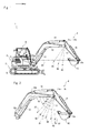
Fig. 1] Fig. 1 is a side view of an entire configuration of a working vehicle according to an embodiment of the present invention. - [
Fig. 2] Fig. 2 is a side view of stop positions of a working device. - [
Fig. 3] Fig. 3 is a block diagram of stop control. - [
Fig. 4] Fig. 4(a) is a drawing of an adjustment selection screen displayed in a display part.Fig. 4(b) is a drawing of an adjustment screen displayed in the display part. - [
Fig. 5] Fig. 5 is a flow chart of adjustment of the stop positions in an input means. - [
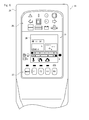
Fig. 6] Fig. 6 is a front view of the display part of the working vehicle. - [
Fig. 7] Fig. 7 is a drawing of a movable range limitation screen displayed in a display device. - [
Fig. 8] Fig. 8 is a flow chart of selection of the stop positions in a control device. - [
Fig. 9] Fig. 9 is a drawing of a restriction position mode transition screen displayed in the display device. - [
Fig. 10] Fig. 10 is a drawing of an excavation mode screen displayed in the display device. - [
Fig. 11] Fig. 11 is a drawing of a restriction surface SET mode screen displayed in the display device. - [
Fig. 12] Fig. 12 is a flow chart of adjustment of the stop positions in the input means according to another embodiment. - Firstly, a
backhoe 1 which is a working vehicle according to an embodiment of the present invention is described referring toFigs. 1 to 3 . Though this embodiment is explained while thebackhoe 1 is regarded as the embodiment of the working vehicle, the working vehicle is not limited thereto and may alternatively be another agricultural vehicle, construction vehicle, industrial vehicle or the like. For make the explanation easy, a direction of an arrow F is regarded as a front direction of thebackhoe 1, and longitudinal and lateral directions at the time of riding on thebackhoe 1 and looking at the forward are regarded as longitudinal and lateral directions of thebackhoe 1. - The
backhoe 1 mainly has atraveling device 2, a revolvingdevice 3 and aworking device 4. - The
traveling device 2 mainly has a pair of left andright crawlers 5. By driving thecrawlers 5 at left and right sides of a vehicle body, thetraveling device 2 can make thebackhoe 1 travel longitudinally and turn. - The revolving
device 3 is a working machine body and mainly has a revolvingbase 6, an operation part 8 and anengine 9. The revolvingbase 6 is a main structure of the revolvingdevice 3. The revolvingbase 6 is arranged above thetraveling device 2 and supported rotatably by thetraveling device 2. In the revolvingdevice 3, by driving a revolving motor (not shown), the revolvingbase 6 can be revolved with respect to thetraveling device 2. On the revolvingbase 6, the operation part 8 having various operation instruments and theengine 9 which is a power source are arranged. - The
working device 4 mainly has aboom 10, anarm 11, abucket 12 which is a kind of an attachment, aboom cylinder 13, anarm cylinder 14, and anattachment cylinder 15. - One of ends of the
boom 10 is supported rotatably on a front part of the revolvingbase 6 by aboom fulcrum 10a which is a joint. Theboom 10 is rotated around theboom fulcrum 10a by theboom cylinder 13 which is driven telescopically. In more detail, when theboom cylinder 13 is extended, theboom 10 is rotated upward, and when theboom cylinder 13 is contracted, theboom 10 is rotated downward. - One of ends of the
arm 11 is supported rotatably on the other end of theboom 10 by anarm fulcrum 11 a which is a joint. Thearm 11 is rotated around the arm fulcrum 11 a at the one of ends by thearm cylinder 14 which is driven telescopically. In more detail, when thearm cylinder 14 is extended, thearm 11 is rotated downward (so as to make the other end of thearm 11 close to the boom 10), and when thearm cylinder 14 is contracted, thearm 11 is rotated upward (so as to separate the other end of thearm 11 from the boom 10). In a support part of thearm 11, aposition sensor 11b detecting a rotation position of thearm 11 is provided. Though a detection means is theposition sensor 11b and detects the rotation position of thearm 11 in this embodiment, the detection means is not limited thereto and may alternatively detect an amount of extension and contraction of thearm cylinder 14. Though theposition sensor 11b which is the detection means is provided only in the arm fulcrum 11 a, the arrangement is not limited thereto and position sensors (angle detection sensors) may alternatively be arranged in theboom fulcrum 10a and anattachment fulcrum 12a so as to grasp a more detailed position of the attachment. - One of ends of the
bucket 12 which is the kind of the attachment is supported rotatably on the other end of thearm 11 by theattachment fulcrum 12a which is a joint. Thebucket 12 is rotated around theattachment fulcrum 12a at the one of ends by theattachment cylinder 15 which is driven telescopically. In more detail, when theattachment cylinder 15 is extended, thebucket 12 is rotated downward (so as to make the other end of thebucket 12 close to the arm 11), and when theattachment cylinder 15 is contracted, thebucket 12 is rotated upward (so as to separate the other end of thebucket 12 from the arm 11). - As the above, in the working
device 4, an articulated structure which digs soil with thebucket 12 is configured. Though the workingdevice 4 which has thebucket 12 and performs digging work is provided in thebackhoe 1 according to this embodiment, the working device is not limited thereto and a working device which has a hydraulic breaker and performs crush work may alternatively be provided. - In the operation part 8, an
operation seat 20 is provided at a substantially center, and a rightoperation lever device 21 and a leftoperation lever device 22 are arranged at right and left sides of theoperation seat 20. With the operation lever devices, the revolving motor, theboom cylinder 13, thearm cylinder 14 and theattachment cylinder 15 can be operated. Adisplay device 23 is provided at one of the lateral sides (in this embodiment, the right side) of theoperation seat 20. Thedisplay device 23 is arranged so as to make a display part thereof opposite to an operator sitting on theoperation seat 20. - Next, stop positions SA, SB and SC which are set for avoiding interference of the working
device 4 is explained. - The stop positions SA, SB and SC of this embodiment are defined by angles between an
upper arm part 10b of theboom 10 and thearm 11 in the state in which theboom fulcrum 10a and theattachment fulcrum 12a are connected with a horizontal line H1 as shown inFigs. 1 and 2 . Namely, at the stop positions SA, SB and SC, when thearm 11 moving toward a raking side reaches stop angles A, B and C with respect to theboom 10, the movement of thearm 11 is stopped. With respect to the stop angles, in the state shown inFig. 2 , a counterclockwise direction is regarded as a positive direction and a clockwise direction is regarded as a negative direction. The plurality of the stop angles A, B and C are set so as to correspond to various attachments. In this embodiment, the stop angles corresponding to the stop positions SA, SB and SC are set so that one of the stop positions SA, SB and SC can be selected suitably, whereby the interference of the workingdevice 4 is prevented. - In an order closer to the revolving
device 3, the stop positions SA, SB and SC are referred to as the first stop position SA at the raking side, the second stop position SB at a central side, and the third stop position SC at an extending side. The first stop angle A is a set value corresponding to the first stop position SA, the second stop angle B is a set value corresponding to the second stop position SB, and the third stop angle C is a set value corresponding to the third stop position SC. A minimum stop angle X corresponding to a position SX at which thearm 11 is the most close to theboom 10 and a maximum stop angle Y corresponding to a position SY at which thearm 11 is separated maximally from theboom 10 are set previously. - The stop positions SA, SB and SC can be adjusted respectively independently. An adjustment range of each of the stop positions SA, SB and SC does not include the values of the other of the stop positions SA, SB and SC. Namely, a range whose setting can be adjusted is set previously with respect to each of the stop positions SA, SB and SC, and the adjustable range of a new first stop angle A1 at the first stop position SA is X ≦ A1 < X1. The adjustable range of a new second stop angle B1 at the second stop position SB is X1 ≦ B1 ≦ X2. The adjustable range of a new third stop angle C1 at the third stop position SC is X2 < C1 ≦ Y. The stop angles used for the adjustable range has a relation X < X1 < X2 < Y.
- Next, a configuration of stop control is explained referring to a block diagram of the configuration of stop control shown in
Fig. 3 and drawings of anadjustment selection screen 53 and anadjustment screen 57 displayed in adisplay part 52 shown inFig. 4 . - A
control device 28 controls aLED display part 25 and a liquidcrystal display part 26 by operating ascreen operation part 27. Thecontrol device 28 is configured in a frame body 24 (seeFig. 6 ) close to theLED display part 25 and the liquidcrystal display part 26 or integrally with anECU 16. - The
ECU 16 controls theengine 9, a hydraulic pump (not shown) and the like. Various programs are stored in theECU 16 so as to control theengine 9, the hydraulic pump and the like. TheECU 16 can perform predetermined calculations according to the programs and store results of the calculations and the like. Substantially, theECU 16 may be configured by connecting a CPU, a ROM, a RAM, a HDD and the like with a bus, or may alternatively be a one-chip LSI or the like. - The
ECU 16 is connected to various sensors and a fuel injection device (not shown) provided in theengine 9 and can control theengine 9. TheECU 16 is connected to thecontrol device 28 of thedisplay device 23, and can transmit signals concerning warning, error information, fuel residual quantity, cooling water temperature and the like to thecontrol device 28 and obtain input signals inputted to thecontrol device 28. - The
control device 28 is connected to theposition sensor 11b which is the detection means, an input means 51 in which the stop angles A, B and C corresponding to the plurality of (three) the stop positions SA, SB and SC are set previously and which the stop angles A, B and C are adjusted independently, and thescreen operation part 27 which is a selection means selecting the plurality of the stop positions SA, SB and SC. - The input means 51 is a personal computer or the like provided separately from the
display device 23 and detachably attached to thecontrol device 28 in thedisplay device 23. By operating the input means 51, the stop positions SA, SB and SC can be adjusted. Though the input means 51 is provided separately in this embodiment, the input means is not limited thereto and may alternatively be inserted into thedisplay device 23 and adjust the stop positions SA, SB and SC. - At the time of adjusting the stop positions SA, SB and SC, the
adjustment selection screen 53 shown inFig. 4(a) is displayed in thedisplay part 52 of the input means 51. In the display screen, anitem 54 of an arm restriction adjustment angle (SC), anitem 55 of an arm restriction adjustment angle (SB), an item 56 of an arm restriction adjustment angle (SA) are displayed. - An operator selects the item to be adjusted from the
items adjustment screen 57 is displayed in thedisplay part 52. Theadjustment screen 57 shown inFig. 4(b) is displayed when the item 56 of the arm restriction adjustment angle (SA) is selected, and the first stop angle A of the first stop position SA is adjusted via theadjustment screen 57. In theadjustment screen 57, an actual value before adjustment (the first stop angle A) is displayed in anitem 61, an adjustable maximum value X1 (strictly, less than X1) is displayed in anitem 62, a new set value (the first stop angle A1 to be adjusted) is displayed in anitem 63, and an adjustable minimum value X is displayed in anitem 64. A unit of the values displayed in theitems - At the right of the
item 63 of the new set value, anadjustment button group 65 is provided. With theadjustment button group 65, the new first stop angle A1 displayed in theitem 63 of the new set value can be adjusted. In theadjustment button group 65, hundredth order, tenth order and first order are provided, and a button for increasing the value and a button for reducing the value are provided in each of the orders. Below theadjustment button group 65, aslide bar 66 is provided, and by sliding theslide bar 66, the new first stop angle A1 of theitem 63 of the new set value can be adjusted. In a lower part of theadjustment screen 57, aset button 67 for storing the adjusted new first stop angle A1 of theitem 63 of the new set value and a cancelbutton 68 for stopping the adjustment on the way are provided. - Next, control steps of the input means 51 adjusting the stop angles A, B and C of the stop positions SA, SB and SC are explained referring to
Figs. 3 to 5 . - Firstly, as shown in
Fig. 3 , the input means 51 is connected to thecontrol device 28 at the side of thebackhoe 1 and started so as to enable the adjustment of the stop angles A, B and C corresponding to the stop positions SA, SB and SC. - Namely, at a step S10 of a flow chart of the adjustment of the stop positions SA, SB and SC in the input means 51 shown in
Fig. 5 , the input means 51 obtains information of the stop positions SA, SB and SC which has been set actually from thecontrol device 28 of thebackhoe 1, and displays the adjustment selection screen 53 (seeFig. 4 ). When an operator selects one of the threeitems adjustment selection screen 53, the control is shifted from the step S10 to a step S11. - At the step S11, the input means 51 judges whether the first stop positions SA (item 56) is selected or not.
- As a result, when the first stop position SA is judged to be selected, the input means 51 shifts from the step S11 to a step S12.
- On the other hand, when the first stop position SA is judged not to be selected, that is, when the second stop position SB or the third stop position SC is judged to be selected, the input means 51 shifts from the step S 11 to a step S21.
- At the step S12, the input means 51 displays the
adjustment screen 57 shown inFig. 4(b) . At this time, the input means 51 displays the adjustable maximum value B and the adjustable minimum value X of the first stop position SA, the first stop angle A which is the actual set value, and the set value A1 to be adjusted in theadjustment screen 57. Then, by operating theadjustment button group 65 or theslide bar 66, a user adjusts the first stop angle A to the new first stop angle A1. - At a step S13, the input means 51 judges whether the user pushes the
set button 67 after adjusting the new first stop angle A1 of the first stop position SA or not. - As a result, when the
set button 67 is judged to be pushed, the input means 51 shifts from the step S13 to a step S14. - On the other hand, when the
set button 67 is judged not to be pushed, the input means 51 shifts from the step S 13 to the step S12 again. - At the step S14, the input means 51 judges whether the adjusted first stop angle A1 is within the adjustable range or not. Namely, the input means 51 judges whether "the stop angle X at which the
arm 11 is the most close to the revolvingdevice 3 ≦ the adjusted first stop angle A1 < the stop angle X1 set previously" or not. - As a result, when the adjusted first stop angle A1 is judged to be within the adjustable range, the input means 51 shifts from the step S 14 to a
step S 15. - On the other hand, when the adjusted first stop angle A1 is judged to be out of the adjustable range, the input means 51 shifts from the step S14 to a step S16. At the step S16, it is displayed that the adjusted first stop angle A1 cannot be adjusted (changed) (the error is displayed), and then the input means 51 shifts from the step S16 to the step S12.
- At the step S15, the input means 51 transmits the adjusted first stop angle A1 as the new first stop angle A to a
storage part 29 of thecontrol device 28 of thebackhoe 1 and finishes the control. - The transferred new first stop angle A1 is updated in the
storage part 29 of thecontrol device 28 by finishing and restarting thebackhoe 1. - At the step S11, when the first stop position SA is judged not to be selected, that is, when the second stop position SB or the third stop position SC is judged to be selected, the input means 51 shifts to the step S21 and judges whether the second stop position SB (item 55) is selected or not.
- As a result, when the second stop position SB is judged to be selected, the input means 51 shifts from the step S21 to a step S22.
- On the other hand, when the second stop position SB is judged not to be selected, that is, when the third stop position SC is judged to be selected, the input means 51 shifts from the step S21 to a step S32.
- At the step S22, the input means 51 displays the
adjustment screen 57 for the second stop position SB. - At this time, the input means 51 displays the second stop angle B which is the actual set value in the
item 61 of theadjustment screen 57, the adjustable maximum value X2 of the second stop position SB in theitem 62, the set value to be adjusted (the second stop angle B1) in theitem 63, and the adjustable minimum value X1 of the second stop position SB in theitem 64. Then, by operating theadjustment button group 65 or theslide bar 66, the user adjusts the second stop angle B to the new second stop angle B1 (see the drawing of the first stop position SA shown inFig. 4(b) ). - At a step S23, the input means 51 judges whether the user pushes the
set button 67 after adjusting the new second stop angle B1 of the second stop position SB or not. - As a result, when the
set button 67 is judged to be pushed, the input means 51 shifts from the step S23 to a step S24. - On the other hand, when the
set button 67 is judged not to be pushed, the input means 51 shifts from the step S23 to the step S22 again. - At the step S24, the input means 51 judges whether the adjusted second stop angle B1 is within the adjustable range or not. Namely, the input means 51 judges whether "the stop angle X1 set previously ≦ the adjusted second stop angle B1 ≦ the stop angle X2 set previously" or not. At this time, the adjusted second stop angle B1 is not less than the stop angle X1 set previously and not more than the stop angle X2 set previously so that the relation among the values of the stop positions SA, SB and SC is not reversed, whereby confusion caused by reversing the magnitude at the time of selecting the plurality of the values of the stop positions is prevented.
- As a result, when the adjusted second stop angle B1 is judged to be within the adjustable range, the input means 51 shifts from the step S24 to a step S25.
- On the other hand, when the adjusted second stop angle B1 is judged to be out of the adjustable range, the input means 51 shifts from the step S24 to a step S26. At the step S26, it is displayed that the adjusted second stop angle B1 cannot be adjusted (changed) (the error is displayed), and then the input means 51 shifts from the step S26 to the step S22 again.
- At the step S25, the input means 51 transmits the adjusted second stop angle B1 as the new second stop angle B to the
storage part 29 of thecontrol device 28 of thebackhoe 1 and finishes the control. - On the other hand, when the control is shifted from the step S21 to the step S32, the input means 51 displays the
adjustment screen 57 for the third stop position SC. - At this time, the input means 51 displays the third stop angle C which is the actual set value in the
item 61 of theadjustment screen 57, the adjustable maximum value Y of the third stop position SC in theitem 62, the set value to be adjusted (the third stop angle C1) in theitem 63, and the adjustable minimum value X2 of the third stop position SC in theitem 64. Then, by operating theadjustment button group 65 or theslide bar 66, the user adjusts the third stop angle C to the new third stop angle C1 (see the drawing of the first stop position SA shown inFig. 4(b) ). - At a step S33, the input means 51 judges whether the user pushes the
set button 67 after adjusting the new third stop angle C1 of the third stop position SC or not. - As a result, when the
set button 67 is judged to be pushed, the input means 51 shifts from the step S33 to a step S34. - On the other hand, when the
set button 67 is judged not to be pushed, the input means 51 shifts from the step S33 to the step S32 again. - At the step S34, the input means 51 judges whether the adjusted third stop angle C1 is within the adjustable range or not. Namely, the input means 51 judges whether "the stop angle X2 set previously ≦ the adjusted third stop angle C1 ≦ the stop angle Y at which the
arm 11 is the most separated from theboom 10" or not. At this time, the adjusted third stop angle C1 is not less than the stop angle X2 set previously so that the relation between the values of the stop positions SB and SC is not reversed, whereby confusion caused by reversing the magnitude at the time of selecting the plurality of the values of the stop positions is prevented. - As a result, when the adjusted third stop angle C1 is judged to be within the adjustable range, the input means 51 shifts from the step S34 to a step S35.
- On the other hand, when the adjusted third stop angle C1 is judged to be out of the adjustable range, the input means 51 shifts from the step S34 to a step S36. At the step S36, it is displayed that the adjusted third stop angle C1 cannot be adjusted (changed) (the error is displayed), and then the input means 51 shifts from the step S36 to the step S32 again.
- At the step S35, the input means 51 transmits the adjusted third stop angle C1 as the new third stop angle C to the
storage part 29 of thecontrol device 28 of thebackhoe 1 and finishes the control. - An application method of the adjusted stop positions SA, SB and SC at the side of the
backhoe 1 is explained. - Firstly, a configuration of the
display device 23 which is an operation instrument for applying the stop positions SA, SB and SC is explained concretely. - As shown in
Figs. 3 and6 , thedisplay device 23 has theframe body 24, theLED display part 25, the liquidcrystal display part 26, thescreen operation part 27, and thecontrol device 28. - The
frame body 24 has an L-like box shape when viewed in side including a longer side and a shorter side. Theframe body 24 is arranged at the right of theoperation seat 20 so as to make a side surface of the shorter side opposite to the operation seat 20 (seeFig. 1 ). - The
LED display part 25 is provided above the side surface of the shorter side of theframe body 24. In theLED display part 25, a plurality of figures showing an operation state of thebackhoe 1 and existence of warning are displayed, and an LED is arranged in each of the figures. In theLED display part 25, only the certain figure is lightened up at a predetermined condition by lighting of the corresponding LED. Accordingly, theLED display part 25 can transmit information to an operator. Though theLED display part 25 performs the display by lighting up the LED in this embodiment, the display is not limited thereto and any light source whose lighting can be controlled may alternatively be used. - The liquid
crystal display part 26 is provided in the side surface of the shorter side of theframe body 24 below theLED display part 25. The liquidcrystal display part 26 includes a liquid crystal screen displaying information. In the liquidcrystal display part 26, by operating thescreen operation part 27 discussed below, the liquid crystal screen is switched to a screen suitable for each of work mode so as to check the operation state of thebackhoe 1. Accordingly, the liquidcrystal display part 26 can transmit information to an operator. Though the liquidcrystal display part 26 is displayed by the liquid crystal screen in this embodiment, the display is not limited thereto and any member which can display a plurality of information may alternatively be used. - The
screen operation part 27 is arranged in the side surface of the shorter side of theframe body 24 below the liquidcrystal display part 26. Thescreen operation part 27 has a menu button and a F1 button, a F2 button, a F3 button and a F4 button which are a plurality of operation button. In thescreen operation part 27, by operating the menu button, the F1 button, the F2 button, the F3 button and the F4 button, the information displayed in the liquidcrystal display part 26 can be selected. - The
control device 28 controls theLED display part 25 and the liquidcrystal display part 26. Thecontrol device 28 is arranged inside theframe body 24 close to theLED display part 25 and the liquidcrystal display part 26 or configured integrally with theECU 16. - Next, a control mode of applying the stop positions SA, SB and SC in the
control device 28 of thedisplay device 23 configured as the above is explained concretely. - In an
excavation mode screen 31 shown inFig. 6 , by selecting the menu button (item) of thescreen operation part 27 and performing suitable selection, a movablerange limitation screen 33 shown inFig. 7 is displayed. - Namely, in a control flow shown in
Fig. 8 , thecontrol device 28 shifts to a step S101 and displays the movablerange limitation screen 33, and obtains the stop position chosen last time (one of SA, SB and SC) and the newest stop angles A, B and C corresponding to the stop positions SA, SB and SC from thestorage part 29 and obtains an arm angle which is an actual angle of thearm 11 from theposition sensor 11b. When the stop position chosen last time does not exist, a default stop position is obtained. In the movablerange limitation screen 33, an operator (setting person) selects "ON" 33a or "SET" 33b and operates the F4 button which is a determination button (seeFig. 7 ). Then, thecontrol device 28 shifts from the step S101 to a step S102. - At the step S102, the
control device 28 judges whether "ON" 33a is selected or not. - As a result, when "ON" 33a is judged to be selected, the
control device 28 shifts from the step S102 to a step S103. - On the other hand, when "ON" 33a is judged not to be selected, that is, when "SET" 33b is selected, the
control device 28 shifts from the step S102 to a step S104. - At the step S103, the
control device 28 displays a restriction positionmode transition screen 32 shown inFig. 9 for a predetermined time, and shifts from the step S103 to a step S105. - At the step S105, the
control device 28 displays theexcavation mode screen 31 in which a stop position control ONmark 100 shown inFig. 10 is lighted up, finishes the control of selection of the stop positions SA, SB and SC, and executes control for avoiding interference of the workingdevice 4. - On the other hand, at the step S104, the
control device 28 displays a restriction positionSET mode screen 34 shown inFig. 11 . In the restriction positionSET mode screen 34, anactual position 34d of the arm obtained at the step S102 and the stop position set last time are displayed. The operator moves avoid triangle mark 34e with F2 and F3 of thescreen operation part 27 and selects suitablestop position marks stop position marks control device 28 shifts from the step S104 to the step S103. - The first
stop position mark 34a, the secondstop position mark 34b and the thirdstop position mark 34c shown inFig. 11 correspond respectively to the first stop position SA, the second stop position SB and the third stop position SC - Actually, the input means 51 may alternatively be configured so that the working
device 4 is moved to the desired stop position, the position (angle) is memorized and the stop position is adjusted. The adjustment of the stop angle with theadjustment button group 65 or theslide bar 66 shown inFig. 4 may alternatively be used together therewith. Namely, a user operates the operation levers 21 and 22 and adjusts visually the stop position of thearm 11, and evaluates the stop position as the stop angle with theposition sensor 11b so as to reflect it to the adjusted first stop angle A1 displayed in theitem 63 of the new set value. - According to the configuration, for example, at the first stop position SA, the
arm 11 is moved actually and evaluated as the first stop angle A1, and at the step S14 shown inFig. 5 , the input means 51 judges whether the first stop angle A1 which is evaluated by moving actually thearm 11 is within the adjustable range or not. Namely, the input means 51 performs the judgement so as to realize a relation of the minimum stop angle X set previously ≦ the first stop angle A1 which is evaluated by moving actually thearm 11 < the stop angle X1 set previously. - Next, the stop positions SA, SB and SC which are set for avoiding interference of the working
device 4 in another embodiment are explained. - An explanation of the same configuration is omitted and explained with the same reference characters as the above embodiment.
- The set angle of each of the stop positions SA, SB and SC of the above embodiment can be changed within the adjustment range set previously. Contrarily, in another embodiment shown below, the adjustment ranges corresponding to the stop positions SA, SB and SC are changed following change of setting of the stop positions SA, SB and SC.
- Namely, the adjustable range of the new first stop angle A1 at the first stop position SA is X ≦ A1 < B. The adjustable range of the new second stop angle B1 at the second stop position SB is A < B1 < C. The adjustable range of the new third stop angle C1 at the third stop position SC is B < C1 ≦ Y. When one of the stop angles A, B and C is adjusted and updated to corresponding one of the new stop angles A1, B1 and C1, the one of the new stop angles A1, B1 and C1 is used as the standard of the adjustable range at the time of adjusting the other stop angles A, B and C. For example, when the first stop angle A is adjusted and updated to the new first stop angle A1 and subsequently the second stop angle B is adjusted, the adjustable range of the new second stop angle B1 is A1 < B1 < C.
- Next, control steps of the input means 51 adjusting the stop angles A, B and C of the stop positions SA, SB and SC are explained referring to
Figs. 3 ,4 and12 . - Firstly, as shown in
Fig. 3 , the input means 51 is connected to thecontrol device 28 at the side of thebackhoe 1 and started so as to enable the adjustment of the stop angles A, B and C corresponding to the stop positions SA, SB and SC. - Namely, at a step S110 of a flow chart of the adjustment of the stop positions SA, SB and SC in the input means 51 shown in
Fig. 12 , the input means 51 obtains information of the stop positions SA, SB and SC which has been set actually from thecontrol device 28 of thebackhoe 1, and displays the adjustment selection screen 53 (seeFig. 4 ). When an operator selects one of the threeitems adjustment selection screen 53, the control is shifted from the step S110 to a step S111. - At the step S111, the input means 51 judges whether the first stop position SA (item 56) is selected or not.
- As a result, when the first stop position SA is judged to be selected, the input means 51 shifts from the step S111 to a step S112.
- On the other hand, when the first stop position SA is judged not to be selected, that is, when the second stop position SB or the third stop position SC is judged to be selected, the input means 51 shifts from the step S111 to a step S121.
- At the
step S 112, the input means 51 displays theadjustment screen 57 shown inFig. 4(b) . At this time, the input means 51 displays the adjustable maximum value B and the adjustable minimum value X of the first stop position SA, the first stop angle A which is the actual set value, and the set value A1 to be adjusted in theadjustment screen 57. Then, by operating theadjustment button group 65 or theslide bar 66, a user adjusts the first stop angle A to the new first stop angle A1. - At a step S113, the input means 51 judges whether the user pushes the
set button 67 after adjusting the new first stop angle A1 of the first stop position SA or not. - As a result, when the
set button 67 is judged to be pushed, the input means 51 shifts from the step S113 to a step S114. - On the other hand, when the
set button 67 is judged not to be pushed, the input means 51 shifts from the step S113 to the step S112 again. - At the step S1114, the input means 51 judges whether the adjusted first stop angle A1 is within the adjustable range or not. Namely, the input means 51 judges whether "the stop angle X at which the
arm 11 is the most close to the revolvingdevice 3 ≦ the adjusted first stop angle A1 < the second stop angle B" or not. - As a result, when the adjusted first stop angle A1 is judged to be within the adjustable range, the input means 51 shifts from the step S114 to a step S115.
- On the other hand, when the adjusted first stop angle A1 is judged to be out of the adjustable range, the input means 51 shifts from the step S114 to a
step S 116. At the step S116, it is displayed that the adjusted first stop angle A1 cannot be adjusted (changed) (the error is displayed), and then the input means 51 shifts from the step S116 to the step S12. - At the step S115, the input means 51 transmits the adjusted first stop angle A1 as the new first stop angle A to a
storage part 29 of thecontrol device 28 and finishes the control. - The transferred new first stop angle A1 is updated in the
storage part 29 of thecontrol device 28 by finishing and restarting thebackhoe 1. - Similarly, when the input means 51 judges that the second stop position SB is selected, at the step S124, the input means 51 judges whether the adjusted second stop angle B1 is within the adjustable range or not. Namely, the input means 51 judges whether "the first stop angle A at the first stop position SA < the adjusted second stop angle B1 < the third stop angle C at the third stop position SC" or not. At this time, the adjusted second stop angle B1 is not less than the first stop angle A and not more than the third stop angle C so that the relation among the values of the stop positions SA, SB and SC is not reversed, whereby confusion caused by reversing the magnitude at the time of selecting the plurality of the values of the stop positions is prevented.
- As a result, when the adjusted second stop angle B1 is judged to be within the adjustable range, the input means 51 shifts from the step S124 to a step S125.
- On the other hand, when the adjusted second stop angle B1 is judged to be out of the adjustable range, the input means 51 shifts from the step S124 to a step S126. At the step S126, it is displayed that the adjusted second stop angle B1 cannot be adjusted (changed) (the error is displayed), and then the input means 51 shifts from the step S126 to the step S122 again.
- Similarly, when the input means 51 judges that the third stop position SC is selected, at the step S134, the input means 51 judges whether the adjusted third stop angle C1 is within the adjustable range or not. Namely, the input means 51 judges whether "the second stop angle B at the second stop position SB < the adjusted third stop angle C1 ≦ the stop angle Y at which the
arm 11 is the most separated from theboom 10" or not. At this time, the adjusted third stop angle C1 is not less than the second stop angle B so that the relation between the values of the stop positions SB and SC is not reversed, whereby confusion caused by reversing the magnitude at the time of selecting the plurality of the values of the stop positions is prevented. - As a result, when the adjusted third stop angle C1 is judged to be within the adjustable range, the input means 51 shifts from the step S134 to a step S135.
- On the other hand, when the adjusted third stop angle C1 is judged to be out of the adjustable range, the input means 51 shifts from the step S134 to a step S136. At the step S136, it is displayed that the adjusted third stop angle C1 cannot be adjusted (changed) (the error is displayed), and then the input means 51 shifts from the step S136 to the step S132 again.
- As the above, the working vehicle (backhoe 1) has the revolving
device 3 which is the working machine body, the workingdevice 4 which is connected to the working machine body and has theboom fulcrum 10a, the arm fulcrum 11 a and theattachment fulcrum 12a which are the plurality of the joints, and whose tip is connected detachably to an attachment, and thecontrol device 28 in which the stop positions SA, SB and SC are set so as to stop the workingdevice 4 for avoiding interference of the workingdevice 4. Thecontrol device 28 is connected to theposition sensor 11b which is the detection means detecting the position of the workingdevice 4, the input means 51 which sets previously the plurality of the stop positions SA, SB and SC and adjusts independently the plurality of the stop positions SA, SB and SC, and thescreen operation part 27 which is the selection means selecting the plurality of the stop positions SA, SB and SC. - According to the configuration, the plurality of the stop positions SA, SB and SC can be adjusted independently, and the adjusted stop position does not affect the other stop positions. Accordingly, when the
attachment 12 is exchanged, readjustment is not required and the interference with theattachment 12 can be avoided, whereby reduction of working efficiency can be relieved. - Concerning each of the plurality of the stop positions SA, SB and SC, the adjustment range which does not include the other stop positions SA, SB and SC is determined.
- According to the configuration, the value of the adjustment range of each of the stop positions SA, SB and SC does not includes the stop positions except for the stop position to be adjusted so that the relation among the values of the stop positions SA, SB and SC in the
screen operation part 27 which is the selection means is not reversed, whereby confusion at the time of selecting the plurality of the values A, B and C of the plurality of the stop positions SA, SB and SC is prevented. - The input means 51 adjusts the stop positions SA, SB and SC by inputting numerical values.
- According to the configuration, the stop positions SA, SB and SC can be adjusted without moving the working
device 4, whereby the adjustment work can be performed easily. - The input means 51 adjusts the stop positions SA, SB and SC by direct teaching which makes the working
device 4 move to the stop positions SA, SB and SC and memorizes the positions. - According to the configuration, at the time of adjusting the stop positions SA, SB and SC, the stop positions SA, SB and SC can be checked visually, whereby the adjustment work can be performed easily. Furthermore, when the adjustment of the stop positions SA, SB and SC with the direct teaching gets out of the adjustment range, the stop positions are not adjusted so that the relation between the values of the stop positions SA, SB and SC (the stop angles A, B and C) in the
screen operation part 27 which is the selection means is not reversed, whereby confusion at the time of selecting the plurality of the values A, B and C of the plurality of the stop positions SA, SB and SC is prevented. - At least a part of the input means 51 is detachably attached to the
control device 28. - According to the configuration, the stop positions SA, SB and SC cannot be adjusted carelessly, whereby the working
device 4 can be operated safely. - The
position sensor 11b which is the detection means detects the angle of thearm fulcrum 11a which is the joint of the workingdevice 4. - According to the configuration, by only detecting the angle of the working device 4 (the stop angles A, B and C), the stop positions SA, SB and SC can be judged, whereby the control configuration can be made simple.
- The present invention can be used for an art of restricting a movable range of a working device of a working vehicle.
-
- 1
- backhoe (working vehicle)
- 3
- revolving device (working machine body)
- 4
- working device
- 10a
- boom fulcrum
- 11a
- arm fulcrum
- 11b
- position sensor
- 12
- attachment
- 12a
- attachment fulcrum
- 27
- screen operation part
- 28
- control device
- 51
- input means
- A
- first stop angle
- B
- second stop angle
- C
- third stop angle
- SA
- first stop position
- SB
- second stop position
- SC
- third stop position
Claims (6)
- A working vehicle comprising:a working machine body;a working machine which is connected to the working machine body and has a plurality of joints and whose tip is connected detachably to an attachment; anda control device in which a stop position is set so as to stop the working device for avoiding interference of the working device,characterized in thatthe control device is connected to a detection means which detects a position of the working device, an input means which sets previously a plurality of stop positions and adjusts independently the plurality of the stop positions, and a selection means which selects the plurality of the stop positions.
- The working vehicle according to claim 1, wherein concerning each of the plurality of the stop positions, an adjustment range which does not include the other stop positions is determined.
- The working vehicle according to claim 1 or 2, wherein the input means adjusts the stop positions by inputting numerical values.
- The working vehicle according to one of claims 1 to 3, wherein the input means adjusts the stop positions by direct teaching which makes the working device move to the stop positions and memorizes the positions.
- The working vehicle according to one of claims 1 to 4, wherein at least a part of the input means is detachably attached to the control device.
- The working vehicle according to one of claims 1 to 5, wherein the detection means detects an angle of the joint of the working device.
Applications Claiming Priority (2)
| Application Number | Priority Date | Filing Date | Title |
|---|---|---|---|
| JP2013017347A JP6101498B2 (en) | 2013-01-31 | 2013-01-31 | Work vehicle |
| PCT/JP2014/051390 WO2014119464A1 (en) | 2013-01-31 | 2014-01-23 | Working vehicle |
Publications (3)
| Publication Number | Publication Date |
|---|---|
| EP2952635A1 true EP2952635A1 (en) | 2015-12-09 |
| EP2952635A4 EP2952635A4 (en) | 2016-09-21 |
| EP2952635B1 EP2952635B1 (en) | 2019-07-31 |
Family
ID=51262178
Family Applications (1)
| Application Number | Title | Priority Date | Filing Date |
|---|---|---|---|
| EP14746810.2A Active EP2952635B1 (en) | 2013-01-31 | 2014-01-23 | Working vehicle |
Country Status (6)
| Country | Link |
|---|---|
| US (1) | US9580886B2 (en) |
| EP (1) | EP2952635B1 (en) |
| JP (1) | JP6101498B2 (en) |
| KR (1) | KR101763374B1 (en) |
| CN (1) | CN105209692B (en) |
| WO (1) | WO2014119464A1 (en) |
Families Citing this family (10)
| Publication number | Priority date | Publication date | Assignee | Title |
|---|---|---|---|---|
| GB2531762A (en) * | 2014-10-29 | 2016-05-04 | Bamford Excavators Ltd | Working machine |
| JP6665412B2 (en) * | 2015-03-23 | 2020-03-13 | 株式会社タダノ | Work machine adjustment devices |
| JP6697361B2 (en) * | 2016-09-21 | 2020-05-20 | 川崎重工業株式会社 | Hydraulic excavator drive system |
| JP7571963B2 (en) * | 2016-09-30 | 2024-10-23 | 住友建機株式会社 | Excavator |
| KR102137469B1 (en) * | 2017-03-29 | 2020-07-24 | 히다찌 겐끼 가부시키가이샤 | Working machine |
| JP2019127725A (en) * | 2018-01-23 | 2019-08-01 | 株式会社クボタ | Work machine, control method of work machine, program, and storage medium for the same |
| US10801180B2 (en) * | 2018-06-11 | 2020-10-13 | Deere & Company | Work machine self protection system |
| FI130526B (en) * | 2020-05-14 | 2023-11-02 | Ponsse Oyj | Arrangement and procedure for controlling at least one function in a work machine and work machine |
| JP7844273B2 (en) * | 2022-06-30 | 2026-04-13 | ヤンマーホールディングス株式会社 | Control method for industrial machinery, control program for industrial machinery, control system for industrial machinery, industrial machinery |
| JP2025082364A (en) | 2023-11-17 | 2025-05-29 | ヤンマーホールディングス株式会社 | Operation lever and construction machine |
Family Cites Families (14)
| Publication number | Priority date | Publication date | Assignee | Title |
|---|---|---|---|---|
| JPH0723621B2 (en) * | 1986-11-10 | 1995-03-15 | 株式会社クボタ | Swivel work vehicle |
| JPH06256405A (en) * | 1993-03-05 | 1994-09-13 | Japan Synthetic Rubber Co Ltd | Method for coagulating polymer latex |
| JP3679848B2 (en) * | 1995-12-27 | 2005-08-03 | 日立建機株式会社 | Construction machine working range restriction control device |
| JP3198249B2 (en) * | 1996-03-21 | 2001-08-13 | 日立建機株式会社 | Construction machine interference prevention equipment |
| US5957989A (en) | 1996-01-22 | 1999-09-28 | Hitachi Construction Machinery Co. Ltd. | Interference preventing system for construction machine |
| JP3308450B2 (en) | 1996-06-26 | 2002-07-29 | 日立建機株式会社 | Construction machine front control device, area setting method and operation panel |
| US6169948B1 (en) | 1996-06-26 | 2001-01-02 | Hitachi Construction Machinery Co., Ltd. | Front control system, area setting method and control panel for construction machine |
| JP3633746B2 (en) | 1997-04-10 | 2005-03-30 | 日立建機株式会社 | Automatic driving excavator |
| NZ501779A (en) * | 1997-07-09 | 2002-02-01 | Crown Equip Corp | Fork lift capacity monitor and display |
| JP4304130B2 (en) * | 2004-07-16 | 2009-07-29 | キャタピラージャパン株式会社 | Work machine |
| JP2010105569A (en) * | 2008-10-30 | 2010-05-13 | Sumitomo (Shi) Construction Machinery Co Ltd | Monitoring screen attachment device of construction machinery |
| US20110301781A1 (en) * | 2008-11-26 | 2011-12-08 | Volvo Construction Equipment | Method for calibrating an angle sensor and vehicle with an angle sensor |
| CN102652200B (en) * | 2010-03-15 | 2014-10-15 | 株式会社小松制作所 | Control device and control method for working mechanism of construction vehicle |
| DE102010048662A1 (en) * | 2010-10-07 | 2012-04-12 | Jungheinrich Aktiengesellschaft | Truck with a height-adjustable load carrier |
-
2013
- 2013-01-31 JP JP2013017347A patent/JP6101498B2/en active Active
-
2014
- 2014-01-23 US US14/765,112 patent/US9580886B2/en not_active Expired - Fee Related
- 2014-01-23 KR KR1020157023465A patent/KR101763374B1/en not_active Expired - Fee Related
- 2014-01-23 CN CN201480007069.5A patent/CN105209692B/en not_active Expired - Fee Related
- 2014-01-23 EP EP14746810.2A patent/EP2952635B1/en active Active
- 2014-01-23 WO PCT/JP2014/051390 patent/WO2014119464A1/en not_active Ceased
Also Published As
| Publication number | Publication date |
|---|---|
| US9580886B2 (en) | 2017-02-28 |
| WO2014119464A1 (en) | 2014-08-07 |
| EP2952635A4 (en) | 2016-09-21 |
| EP2952635B1 (en) | 2019-07-31 |
| CN105209692A (en) | 2015-12-30 |
| US20150368876A1 (en) | 2015-12-24 |
| CN105209692B (en) | 2017-05-10 |
| KR101763374B1 (en) | 2017-07-31 |
| KR20150110801A (en) | 2015-10-02 |
| JP6101498B2 (en) | 2017-03-22 |
| JP2014148806A (en) | 2014-08-21 |
Similar Documents
| Publication | Publication Date | Title |
|---|---|---|
| EP2952635B1 (en) | Working vehicle | |
| KR102333772B1 (en) | shovel display device | |
| EP3604684B1 (en) | Work machinery | |
| JP6072993B1 (en) | Work vehicle control system, control method, and work vehicle | |
| EP4006235B1 (en) | Excavator | |
| EP3214229B1 (en) | Work vehicle | |
| CN108350680B (en) | Operation aids for work machines | |
| CN104662232A (en) | Automatic grading system for construction machine and method for controlling the same | |
| KR20150082601A (en) | Construction machinery display system and control method for same | |
| CN112601867B (en) | Working machine | |
| JP2018080510A (en) | Work machine | |
| KR20230057486A (en) | Work vehicle | |
| KR20180073642A (en) | Control method of working vehicle and working vehicle | |
| CN108884668A (en) | excavator | |
| CN103180523B (en) | Working truck | |
| EP4317619A1 (en) | Work machine display control system, work machine display system, work machine, work machine display control method, and work machine display control program | |
| JP2017186875A (en) | Control system of work vehicle, control method, and work vehicle | |
| KR20160040715A (en) | Industrial vehicle | |
| JP2024075941A (en) | CONTROL METHOD FOR CONTROLLING A WORK MACHINE, CONTROL PROGRAM FOR CONTROLLING A WORK MACHINE, AND CONTROL SYSTEM FOR CONTROLLING A WORK MACHINE | |
| US20240157794A1 (en) | Display Device For Tractor | |
| JP5781971B2 (en) | Work vehicle | |
| EP3907334A1 (en) | Work machine and work machine control method | |
| EP3907333A1 (en) | Work machine calibration method, work machine controller, and work machine |
Legal Events
| Date | Code | Title | Description |
|---|---|---|---|
| PUAI | Public reference made under article 153(3) epc to a published international application that has entered the european phase |
Free format text: ORIGINAL CODE: 0009012 |
|
| 17P | Request for examination filed |
Effective date: 20150831 |
|
| AK | Designated contracting states |
Kind code of ref document: A1 Designated state(s): AL AT BE BG CH CY CZ DE DK EE ES FI FR GB GR HR HU IE IS IT LI LT LU LV MC MK MT NL NO PL PT RO RS SE SI SK SM TR |
|
| AX | Request for extension of the european patent |
Extension state: BA ME |
|
| DAX | Request for extension of the european patent (deleted) | ||
| A4 | Supplementary search report drawn up and despatched |
Effective date: 20160819 |
|
| RIC1 | Information provided on ipc code assigned before grant |
Ipc: E02F 9/24 20060101ALI20160812BHEP Ipc: E02F 9/26 20060101ALI20160812BHEP Ipc: E02F 9/20 20060101ALI20160812BHEP Ipc: E02F 3/43 20060101AFI20160812BHEP |
|
| RIC1 | Information provided on ipc code assigned before grant |
Ipc: E02F 9/26 20060101ALI20170116BHEP Ipc: E02F 9/24 20060101ALI20170116BHEP Ipc: E02F 3/43 20060101AFI20170116BHEP Ipc: E02F 9/20 20060101ALI20170116BHEP |
|
| STAA | Information on the status of an ep patent application or granted ep patent |
Free format text: STATUS: EXAMINATION IS IN PROGRESS |
|
| 17Q | First examination report despatched |
Effective date: 20180514 |
|
| GRAP | Despatch of communication of intention to grant a patent |
Free format text: ORIGINAL CODE: EPIDOSNIGR1 |
|
| STAA | Information on the status of an ep patent application or granted ep patent |
Free format text: STATUS: GRANT OF PATENT IS INTENDED |
|
| INTG | Intention to grant announced |
Effective date: 20190221 |
|
| RIN1 | Information on inventor provided before grant (corrected) |
Inventor name: TANAKA, KATASHI Inventor name: NAKAGAKI, MITSUHIRO Inventor name: TAKAHASHI, MITSUHIRO Inventor name: MIYAZAKI, KATSUYA |
|
| GRAS | Grant fee paid |
Free format text: ORIGINAL CODE: EPIDOSNIGR3 |
|
| GRAA | (expected) grant |
Free format text: ORIGINAL CODE: 0009210 |
|
| STAA | Information on the status of an ep patent application or granted ep patent |
Free format text: STATUS: THE PATENT HAS BEEN GRANTED |
|
| RIN1 | Information on inventor provided before grant (corrected) |
Inventor name: TANAKA, KATASHI Inventor name: MIYAZAKI, KATSUYA Inventor name: NAKAGAKI, MITSUHIRO Inventor name: TAKAHASHI, MITSUHIRO |
|
| AK | Designated contracting states |
Kind code of ref document: B1 Designated state(s): AL AT BE BG CH CY CZ DE DK EE ES FI FR GB GR HR HU IE IS IT LI LT LU LV MC MK MT NL NO PL PT RO RS SE SI SK SM TR |
|
| REG | Reference to a national code |
Ref country code: CH Ref legal event code: EP Ref country code: GB Ref legal event code: FG4D |
|
| REG | Reference to a national code |
Ref country code: DE Ref legal event code: R096 Ref document number: 602014050872 Country of ref document: DE |
|
| REG | Reference to a national code |
Ref country code: AT Ref legal event code: REF Ref document number: 1161017 Country of ref document: AT Kind code of ref document: T Effective date: 20190815 |
|
| REG | Reference to a national code |
Ref country code: IE Ref legal event code: FG4D |
|
| REG | Reference to a national code |
Ref country code: NL Ref legal event code: MP Effective date: 20190731 |
|
| REG | Reference to a national code |
Ref country code: LT Ref legal event code: MG4D |
|
| REG | Reference to a national code |
Ref country code: AT Ref legal event code: MK05 Ref document number: 1161017 Country of ref document: AT Kind code of ref document: T Effective date: 20190731 |
|
| PG25 | Lapsed in a contracting state [announced via postgrant information from national office to epo] |
Ref country code: NO Free format text: LAPSE BECAUSE OF FAILURE TO SUBMIT A TRANSLATION OF THE DESCRIPTION OR TO PAY THE FEE WITHIN THE PRESCRIBED TIME-LIMIT Effective date: 20191031 Ref country code: AT Free format text: LAPSE BECAUSE OF FAILURE TO SUBMIT A TRANSLATION OF THE DESCRIPTION OR TO PAY THE FEE WITHIN THE PRESCRIBED TIME-LIMIT Effective date: 20190731 Ref country code: PT Free format text: LAPSE BECAUSE OF FAILURE TO SUBMIT A TRANSLATION OF THE DESCRIPTION OR TO PAY THE FEE WITHIN THE PRESCRIBED TIME-LIMIT Effective date: 20191202 Ref country code: BG Free format text: LAPSE BECAUSE OF FAILURE TO SUBMIT A TRANSLATION OF THE DESCRIPTION OR TO PAY THE FEE WITHIN THE PRESCRIBED TIME-LIMIT Effective date: 20191031 Ref country code: LT Free format text: LAPSE BECAUSE OF FAILURE TO SUBMIT A TRANSLATION OF THE DESCRIPTION OR TO PAY THE FEE WITHIN THE PRESCRIBED TIME-LIMIT Effective date: 20190731 Ref country code: NL Free format text: LAPSE BECAUSE OF FAILURE TO SUBMIT A TRANSLATION OF THE DESCRIPTION OR TO PAY THE FEE WITHIN THE PRESCRIBED TIME-LIMIT Effective date: 20190731 Ref country code: FI Free format text: LAPSE BECAUSE OF FAILURE TO SUBMIT A TRANSLATION OF THE DESCRIPTION OR TO PAY THE FEE WITHIN THE PRESCRIBED TIME-LIMIT Effective date: 20190731 Ref country code: HR Free format text: LAPSE BECAUSE OF FAILURE TO SUBMIT A TRANSLATION OF THE DESCRIPTION OR TO PAY THE FEE WITHIN THE PRESCRIBED TIME-LIMIT Effective date: 20190731 Ref country code: SE Free format text: LAPSE BECAUSE OF FAILURE TO SUBMIT A TRANSLATION OF THE DESCRIPTION OR TO PAY THE FEE WITHIN THE PRESCRIBED TIME-LIMIT Effective date: 20190731 |
|
| PG25 | Lapsed in a contracting state [announced via postgrant information from national office to epo] |
Ref country code: GR Free format text: LAPSE BECAUSE OF FAILURE TO SUBMIT A TRANSLATION OF THE DESCRIPTION OR TO PAY THE FEE WITHIN THE PRESCRIBED TIME-LIMIT Effective date: 20191101 Ref country code: AL Free format text: LAPSE BECAUSE OF FAILURE TO SUBMIT A TRANSLATION OF THE DESCRIPTION OR TO PAY THE FEE WITHIN THE PRESCRIBED TIME-LIMIT Effective date: 20190731 Ref country code: ES Free format text: LAPSE BECAUSE OF FAILURE TO SUBMIT A TRANSLATION OF THE DESCRIPTION OR TO PAY THE FEE WITHIN THE PRESCRIBED TIME-LIMIT Effective date: 20190731 Ref country code: IS Free format text: LAPSE BECAUSE OF FAILURE TO SUBMIT A TRANSLATION OF THE DESCRIPTION OR TO PAY THE FEE WITHIN THE PRESCRIBED TIME-LIMIT Effective date: 20191130 Ref country code: RS Free format text: LAPSE BECAUSE OF FAILURE TO SUBMIT A TRANSLATION OF THE DESCRIPTION OR TO PAY THE FEE WITHIN THE PRESCRIBED TIME-LIMIT Effective date: 20190731 Ref country code: LV Free format text: LAPSE BECAUSE OF FAILURE TO SUBMIT A TRANSLATION OF THE DESCRIPTION OR TO PAY THE FEE WITHIN THE PRESCRIBED TIME-LIMIT Effective date: 20190731 |
|
| PG25 | Lapsed in a contracting state [announced via postgrant information from national office to epo] |
Ref country code: TR Free format text: LAPSE BECAUSE OF FAILURE TO SUBMIT A TRANSLATION OF THE DESCRIPTION OR TO PAY THE FEE WITHIN THE PRESCRIBED TIME-LIMIT Effective date: 20190731 |
|
| PG25 | Lapsed in a contracting state [announced via postgrant information from national office to epo] |
Ref country code: RO Free format text: LAPSE BECAUSE OF FAILURE TO SUBMIT A TRANSLATION OF THE DESCRIPTION OR TO PAY THE FEE WITHIN THE PRESCRIBED TIME-LIMIT Effective date: 20190731 Ref country code: DK Free format text: LAPSE BECAUSE OF FAILURE TO SUBMIT A TRANSLATION OF THE DESCRIPTION OR TO PAY THE FEE WITHIN THE PRESCRIBED TIME-LIMIT Effective date: 20190731 Ref country code: EE Free format text: LAPSE BECAUSE OF FAILURE TO SUBMIT A TRANSLATION OF THE DESCRIPTION OR TO PAY THE FEE WITHIN THE PRESCRIBED TIME-LIMIT Effective date: 20190731 Ref country code: PL Free format text: LAPSE BECAUSE OF FAILURE TO SUBMIT A TRANSLATION OF THE DESCRIPTION OR TO PAY THE FEE WITHIN THE PRESCRIBED TIME-LIMIT Effective date: 20190731 |
|
| PG25 | Lapsed in a contracting state [announced via postgrant information from national office to epo] |
Ref country code: IS Free format text: LAPSE BECAUSE OF FAILURE TO SUBMIT A TRANSLATION OF THE DESCRIPTION OR TO PAY THE FEE WITHIN THE PRESCRIBED TIME-LIMIT Effective date: 20200224 Ref country code: SK Free format text: LAPSE BECAUSE OF FAILURE TO SUBMIT A TRANSLATION OF THE DESCRIPTION OR TO PAY THE FEE WITHIN THE PRESCRIBED TIME-LIMIT Effective date: 20190731 Ref country code: CZ Free format text: LAPSE BECAUSE OF FAILURE TO SUBMIT A TRANSLATION OF THE DESCRIPTION OR TO PAY THE FEE WITHIN THE PRESCRIBED TIME-LIMIT Effective date: 20190731 Ref country code: SM Free format text: LAPSE BECAUSE OF FAILURE TO SUBMIT A TRANSLATION OF THE DESCRIPTION OR TO PAY THE FEE WITHIN THE PRESCRIBED TIME-LIMIT Effective date: 20190731 |
|
| REG | Reference to a national code |
Ref country code: DE Ref legal event code: R097 Ref document number: 602014050872 Country of ref document: DE |
|
| PLBE | No opposition filed within time limit |
Free format text: ORIGINAL CODE: 0009261 |
|
| STAA | Information on the status of an ep patent application or granted ep patent |
Free format text: STATUS: NO OPPOSITION FILED WITHIN TIME LIMIT |
|
| PG2D | Information on lapse in contracting state deleted |
Ref country code: IS |
|
| PG25 | Lapsed in a contracting state [announced via postgrant information from national office to epo] |
Ref country code: IS Free format text: LAPSE BECAUSE OF FAILURE TO SUBMIT A TRANSLATION OF THE DESCRIPTION OR TO PAY THE FEE WITHIN THE PRESCRIBED TIME-LIMIT Effective date: 20191030 |
|
| 26N | No opposition filed |
Effective date: 20200603 |
|
| PG25 | Lapsed in a contracting state [announced via postgrant information from national office to epo] |
Ref country code: SI Free format text: LAPSE BECAUSE OF FAILURE TO SUBMIT A TRANSLATION OF THE DESCRIPTION OR TO PAY THE FEE WITHIN THE PRESCRIBED TIME-LIMIT Effective date: 20190731 Ref country code: MC Free format text: LAPSE BECAUSE OF FAILURE TO SUBMIT A TRANSLATION OF THE DESCRIPTION OR TO PAY THE FEE WITHIN THE PRESCRIBED TIME-LIMIT Effective date: 20190731 |
|
| REG | Reference to a national code |
Ref country code: CH Ref legal event code: PL |
|
| REG | Reference to a national code |
Ref country code: BE Ref legal event code: MM Effective date: 20200131 |
|
| REG | Reference to a national code |
Ref country code: DE Ref legal event code: R082 Ref document number: 602014050872 Country of ref document: DE Representative=s name: JOSTARNDT PATENTANWALTS-AG, DE Ref country code: DE Ref legal event code: R081 Ref document number: 602014050872 Country of ref document: DE Owner name: YANMAR POWER TECHNOLOGY CO., LTD., JP Free format text: FORMER OWNER: YANMAR CO., LTD., OSAKA-SHI, JP |
|
| PG25 | Lapsed in a contracting state [announced via postgrant information from national office to epo] |
Ref country code: LU Free format text: LAPSE BECAUSE OF NON-PAYMENT OF DUE FEES Effective date: 20200123 |
|
| PG25 | Lapsed in a contracting state [announced via postgrant information from national office to epo] |
Ref country code: LI Free format text: LAPSE BECAUSE OF NON-PAYMENT OF DUE FEES Effective date: 20200131 Ref country code: CH Free format text: LAPSE BECAUSE OF NON-PAYMENT OF DUE FEES Effective date: 20200131 Ref country code: BE Free format text: LAPSE BECAUSE OF NON-PAYMENT OF DUE FEES Effective date: 20200131 |
|
| PG25 | Lapsed in a contracting state [announced via postgrant information from national office to epo] |
Ref country code: IE Free format text: LAPSE BECAUSE OF NON-PAYMENT OF DUE FEES Effective date: 20200123 |
|
| PGFP | Annual fee paid to national office [announced via postgrant information from national office to epo] |
Ref country code: GB Payment date: 20220119 Year of fee payment: 9 |
|
| PG25 | Lapsed in a contracting state [announced via postgrant information from national office to epo] |
Ref country code: MT Free format text: LAPSE BECAUSE OF FAILURE TO SUBMIT A TRANSLATION OF THE DESCRIPTION OR TO PAY THE FEE WITHIN THE PRESCRIBED TIME-LIMIT Effective date: 20190731 Ref country code: CY Free format text: LAPSE BECAUSE OF FAILURE TO SUBMIT A TRANSLATION OF THE DESCRIPTION OR TO PAY THE FEE WITHIN THE PRESCRIBED TIME-LIMIT Effective date: 20190731 |
|
| PGFP | Annual fee paid to national office [announced via postgrant information from national office to epo] |
Ref country code: IT Payment date: 20220120 Year of fee payment: 9 |
|
| PG25 | Lapsed in a contracting state [announced via postgrant information from national office to epo] |
Ref country code: MK Free format text: LAPSE BECAUSE OF FAILURE TO SUBMIT A TRANSLATION OF THE DESCRIPTION OR TO PAY THE FEE WITHIN THE PRESCRIBED TIME-LIMIT Effective date: 20190731 |
|
| PGFP | Annual fee paid to national office [announced via postgrant information from national office to epo] |
Ref country code: FR Payment date: 20230124 Year of fee payment: 10 |
|
| PGFP | Annual fee paid to national office [announced via postgrant information from national office to epo] |
Ref country code: DE Payment date: 20230123 Year of fee payment: 10 |
|
| GBPC | Gb: european patent ceased through non-payment of renewal fee |
Effective date: 20230123 |
|
| PG25 | Lapsed in a contracting state [announced via postgrant information from national office to epo] |
Ref country code: GB Free format text: LAPSE BECAUSE OF NON-PAYMENT OF DUE FEES Effective date: 20230123 |
|
| PG25 | Lapsed in a contracting state [announced via postgrant information from national office to epo] |
Ref country code: IT Free format text: LAPSE BECAUSE OF NON-PAYMENT OF DUE FEES Effective date: 20230123 |
|
| REG | Reference to a national code |
Ref country code: DE Ref legal event code: R119 Ref document number: 602014050872 Country of ref document: DE |
|
| PG25 | Lapsed in a contracting state [announced via postgrant information from national office to epo] |
Ref country code: DE Free format text: LAPSE BECAUSE OF NON-PAYMENT OF DUE FEES Effective date: 20240801 |
|
| PG25 | Lapsed in a contracting state [announced via postgrant information from national office to epo] |
Ref country code: FR Free format text: LAPSE BECAUSE OF NON-PAYMENT OF DUE FEES Effective date: 20240131 |
|
| PG25 | Lapsed in a contracting state [announced via postgrant information from national office to epo] |
Ref country code: FR Free format text: LAPSE BECAUSE OF NON-PAYMENT OF DUE FEES Effective date: 20240131 Ref country code: DE Free format text: LAPSE BECAUSE OF NON-PAYMENT OF DUE FEES Effective date: 20240801 |