EP2952627A1 - Steel cord and elastic track using same - Google Patents
Steel cord and elastic track using same Download PDFInfo
- Publication number
- EP2952627A1 EP2952627A1 EP14754227.8A EP14754227A EP2952627A1 EP 2952627 A1 EP2952627 A1 EP 2952627A1 EP 14754227 A EP14754227 A EP 14754227A EP 2952627 A1 EP2952627 A1 EP 2952627A1
- Authority
- EP
- European Patent Office
- Prior art keywords
- core
- sheath
- wires
- cord
- strand
- Prior art date
- Legal status (The legal status is an assumption and is not a legal conclusion. Google has not performed a legal analysis and makes no representation as to the accuracy of the status listed.)
- Granted
Links
Images




Classifications
-
- D—TEXTILES; PAPER
- D07—ROPES; CABLES OTHER THAN ELECTRIC
- D07B—ROPES OR CABLES IN GENERAL
- D07B1/00—Constructional features of ropes or cables
- D07B1/06—Ropes or cables built-up from metal wires, e.g. of section wires around a hemp core
- D07B1/0693—Ropes or cables built-up from metal wires, e.g. of section wires around a hemp core having a strand configuration
-
- D—TEXTILES; PAPER
- D07—ROPES; CABLES OTHER THAN ELECTRIC
- D07B—ROPES OR CABLES IN GENERAL
- D07B1/00—Constructional features of ropes or cables
- D07B1/06—Ropes or cables built-up from metal wires, e.g. of section wires around a hemp core
- D07B1/0606—Reinforcing cords for rubber or plastic articles
- D07B1/0613—Reinforcing cords for rubber or plastic articles the reinforcing cords being characterised by the rope configuration
-
- B—PERFORMING OPERATIONS; TRANSPORTING
- B62—LAND VEHICLES FOR TRAVELLING OTHERWISE THAN ON RAILS
- B62D—MOTOR VEHICLES; TRAILERS
- B62D55/00—Endless track vehicles
- B62D55/08—Endless track units; Parts thereof
- B62D55/18—Tracks
- B62D55/24—Tracks of continuously flexible type, e.g. rubber belts
- B62D55/244—Moulded in one piece, with either smooth surfaces or surfaces having projections, e.g. incorporating reinforcing elements
-
- D—TEXTILES; PAPER
- D07—ROPES; CABLES OTHER THAN ELECTRIC
- D07B—ROPES OR CABLES IN GENERAL
- D07B1/00—Constructional features of ropes or cables
- D07B1/06—Ropes or cables built-up from metal wires, e.g. of section wires around a hemp core
- D07B1/0606—Reinforcing cords for rubber or plastic articles
- D07B1/062—Reinforcing cords for rubber or plastic articles the reinforcing cords being characterised by the strand configuration
-
- D—TEXTILES; PAPER
- D07—ROPES; CABLES OTHER THAN ELECTRIC
- D07B—ROPES OR CABLES IN GENERAL
- D07B1/00—Constructional features of ropes or cables
- D07B1/06—Ropes or cables built-up from metal wires, e.g. of section wires around a hemp core
- D07B1/0606—Reinforcing cords for rubber or plastic articles
- D07B1/062—Reinforcing cords for rubber or plastic articles the reinforcing cords being characterised by the strand configuration
- D07B1/0626—Reinforcing cords for rubber or plastic articles the reinforcing cords being characterised by the strand configuration the reinforcing cords consisting of three core wires or filaments and at least one layer of outer wires or filaments, i.e. a 3+N configuration
-
- D—TEXTILES; PAPER
- D07—ROPES; CABLES OTHER THAN ELECTRIC
- D07B—ROPES OR CABLES IN GENERAL
- D07B2201/00—Ropes or cables
- D07B2201/10—Rope or cable structures
- D07B2201/104—Rope or cable structures twisted
- D07B2201/1076—Open winding
-
- D—TEXTILES; PAPER
- D07—ROPES; CABLES OTHER THAN ELECTRIC
- D07B—ROPES OR CABLES IN GENERAL
- D07B2201/00—Ropes or cables
- D07B2201/20—Rope or cable components
- D07B2201/2001—Wires or filaments
- D07B2201/2006—Wires or filaments characterised by a value or range of the dimension given
-
- D—TEXTILES; PAPER
- D07—ROPES; CABLES OTHER THAN ELECTRIC
- D07B—ROPES OR CABLES IN GENERAL
- D07B2201/00—Ropes or cables
- D07B2201/20—Rope or cable components
- D07B2201/2015—Strands
- D07B2201/202—Strands characterised by a value or range of the dimension given
-
- D—TEXTILES; PAPER
- D07—ROPES; CABLES OTHER THAN ELECTRIC
- D07B—ROPES OR CABLES IN GENERAL
- D07B2201/00—Ropes or cables
- D07B2201/20—Rope or cable components
- D07B2201/2015—Strands
- D07B2201/2024—Strands twisted
- D07B2201/2029—Open winding
-
- D—TEXTILES; PAPER
- D07—ROPES; CABLES OTHER THAN ELECTRIC
- D07B—ROPES OR CABLES IN GENERAL
- D07B2201/00—Ropes or cables
- D07B2201/20—Rope or cable components
- D07B2201/2047—Cores
- D07B2201/2051—Cores characterised by a value or range of the dimension given
-
- D—TEXTILES; PAPER
- D07—ROPES; CABLES OTHER THAN ELECTRIC
- D07B—ROPES OR CABLES IN GENERAL
- D07B2201/00—Ropes or cables
- D07B2201/20—Rope or cable components
- D07B2201/2047—Cores
- D07B2201/2052—Cores characterised by their structure
- D07B2201/2059—Cores characterised by their structure comprising wires
- D07B2201/2061—Cores characterised by their structure comprising wires resulting in a twisted structure
-
- D—TEXTILES; PAPER
- D07—ROPES; CABLES OTHER THAN ELECTRIC
- D07B—ROPES OR CABLES IN GENERAL
- D07B2201/00—Ropes or cables
- D07B2201/20—Rope or cable components
- D07B2201/2047—Cores
- D07B2201/2067—Cores characterised by the elongation or tension behaviour
- D07B2201/2068—Cores characterised by the elongation or tension behaviour having a load bearing function
Definitions
- the present invention relates to a steel cord, which is suitable for a tensile strength cord of the elastic crawler and is capable of preventing wire center-core dislocation in a core and early breakage of the wire in the core, and an elastic crawler using the same
- a crawler type traveling device adopted in the traveling section of an agricultural machine, a constructing machine and the like comprises an endless band-formed elastic crawler wound revolvably by a driving wheel (sprocket), an idler, tracker roller and the like.
- the elastic crawler comprises an endless band-formed crawler main body made of rubber elastic material and a tensile member for reinforcement embedded in it.
- the tensile member comprises a plurality of tensile strength cords extending continuously in a crawler circumferential direction.
- an el ongated band body is once wound in the crawl er ci rcumferenti al di recti on and its circumferential both ends are superimposed and connected so as to form the endless band-formed tensi 1 e member.
- the band body is formed by coating an array body of the tensile strength cord arranged in the longitudinal direction with topping rubber.
- a steel cord having a structure of 7 ⁇ (1+6), which comprises seven strands A each having the same 1+6 structure is proposed as the tensile strength cord (Patent Document 1, for example). That is to say, the tensile strength cord comprises a core B made of a single strand A and a sheath C formed by twisting six strands A disposed around the core B.
- the applicant of the present invention proposes to employ the 3+6+12 layer-twisted structure for the strand A of the core B.
- this structure comprises, a central portion formed by twisting three wires (a1), a first external layer portion formed by twisting six wires (a2) disposed around the central portion, and a second external layer portion formed by twisting twelve wires (a3) disposed around the fi rst external layer (see Patent Document 2).
- the central portion of the core B is formed by twisting the three wires (a1), it produces an effect on center-core dislocation of the core B.
- the thicknesses (diameters) of the wires (a1), (a2), (a3) of the core B therefore, it produces no effect on the early breakage of the wire in the core B.
- the present invention aims to provide a steel cord, which enable to be used as a tensile strength cord of the elastic crawler and to reduce center-core dislocation of a wire and early breakage of the wire in a core, and an elastic crawler using the same.
- a steel cord comprises a core formed of a single core strand, and a sheath formed by twisting together six sheath strands arranged around the core.
- the core strand has a layer-twisted structure comprising a center-core portion formed by twisting together three core wi res and an external layer portion formed by twisting together the eight to nine core wi res arranged around the center-core portion.
- the sheath strand each has either a bundle-twisted structure formed by bundling and twisting twelve to nineteen sheath wires, or a multi-layer twisted structure formed by twisting twelve to nineteen sheath wires in layers.
- a diameter (dc) of each of the core wires is greater than a diameter (ds) of each of the sheath wi res.
- an average gap (Gc) between the core wi res of the external layer portion is not less than 0.015 mm, and an average gap (Gs) between the sheath strands is not less than 0.1 mm.
- a real cord cross-sectional area S1 which is a sum total of a sum of wire cross-sectional area of the core wire and a sum of a wire cross-sectional area of the sheath wire, is more than 48% and less than 51% of a apparent cord cross-sectional area SO, which is an area of the smallest diameter circumscribed ci rcl e among ci rcumscri bed circles surrounding the steel cord.
- a diameter Dc of the core strand of more than 35% of a diameter DO of the steel cord.
- an elastic crawler including an endless band-formed crawler main body made of rubber elastic material, and a tensile member embedded in the crawler main body.
- the tensile member comprises a plurality of tensile strength cords continuously extending in the crawler circumferential direction. And for the tensile strength cord, the steel cord as set forth in any one of claims 1 to 3 is employed.
- the core strand is formed of the core wires each having the same wire diameter.
- the sheath strand can be formed of the sheath wires each having the same wire diameter and also be formed of the sheath wires having different wire diameters.
- the di ameter (dc) of the core wi re is set to be larger than the di ameter (ds) of the sheath wire, thereby inhibiting the early breakage of the wire in the core strand.
- the core strand is constricted by the sheath strands; therefore, tightening load unnecessarily acts on the wire of the core strand as compared to the wire of the sheath strand, also contact pressure between the wires increases.
- the core wire is set to be thicker than the sheath wire thereby the strength of the core being relatively high compared with that of the sheath wire.
- the core strand is formed of the same core wires. That is to say, since the strength of each wire forming the core strand is even, a weak point of the strength can be cleared out. As a result, it is possible to effectively suppress the early breakage.
- an average gap Gc between the core wi res in the external layer portion is set to not less than 0.015 mm, and the average gap Gs between the sheath strands is set to not less than 0.1 mm. Accordingly, those would be enough to ensure rubber permeability around the core strand and into the core strand. In consequence, owing to the adhesion with penetrating rubber, the center-core dislocation of the center-core portion can be inhibited more. And, the penetrating rubber lightens up the tightening load to the core wi re and the contact pressure between the core wires; thereby the early breakage in the core wire can be inhibited all the more.
- the sheath strand when the sheath strand is set to have a 1 ⁇ M bundle-twisted structure, its cross-section is compact, and the average gap Gs would be enough to be ensured while having the same steel quantity. Also, si nce the contact area between the sheath wi res is large owing to the employment of the bundle-twisted structure, it helps to inhibit fretting wear. And when the sheath strand has a multi-layer twisted structure, the sheath strand can improve the stability of twisting form.
- Fig. 1 is a si de vi ew showing a part of a vehi cl e 2 fi tted wi th an el asti c crawler 1 according to the present invention.
- the vehicle 2 comprises a driving wheel 3, an idler 4, and a plurality of tracker rollers 5 on both sides of the vehicle body, respectively.
- the driving wheel 3 is located on one side in the advancing direction of vehicle (front-side end, in the present embodiment). To improve running performance for climbing over protrusion from a road surface S, the driving wheel 3 is located apart above from the road surface S.
- the driving wheel 3 of the present embodiment comprises, as conceptually shown in Fig. 2 , a pair of wheel portions 7 attached to the both ends of a central shaft 6.
- Each of the wheel portions 7 comprises discoidal side plates 7A concentrically fixed to the central shaft 6, and a cylindrical flange portion 7B bent outwardly in the axial di recti on from the outer perimeter edge of the side plates 7A.
- a plurality of engaging pins 9 are disposed between the side plates 7A, 7A at regular intervals in the circumferential direction. The engaging pins 9 interlock with projection portions 8 disposed on the elastic crawler 1 to transmit the power to the elastic crawler 1
- the idler 4 is provided on the other end in the advancing direction of vehicle (rear-side end, in the present embodiment), and rotates dependently on the circularly movement of the elastic crawler 1.
- the tracker roller 5 guides the elastic crawler 1 so as to go around between the driving wheel 3 and the idler 4 while pressing the elastic crawler 1 on the road surface S. Therefore, the vehicle 2 can run.
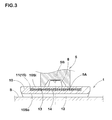
- This tracker roller 5 comprises, in the present embodiment, as shown in Fig. 3 , a large-diameter pressing surface portion 5A positioned on the both end sides in the axial direction and pressing the elastic crawler 1 on the road surface S, and a small-diameter concave portion 5B positioned on a middle side in the axial direction to avoid impingement with the projection portion 8 of the elastic crawler 1 while running.
- the elastic crawler 1 includes, as shown in Figs. 1 and 3 , an endless band-formed crawler main body 10 made of rubber elastic material, and a tensile member 11 embedded in the crawler main body 10.
- the crawler main body 10 is provided on an inner periphery 10Si with a plurality of projection portions 8.
- the projection portions 8 interlock with the engaging pins 9 located in the driving wheel 3 and transmit the power from the driving wheel 3.
- the projection portions 8 and the engaging pins 9 are therefore arranged in the crawler circumferential direction at regular pitches.
- each of the projection portions 8 has a square-pyramid-trapezoidal shape, but is not limited to.
- the driving wheel 3 can be liberally provided with groove portions such as in a sprocket or in a gear and the projection portions 8 of the crawler main body 10 is formed as tooth so as to interlocking with the groove portion.
- Each of the projection portions 8 is formed of the same rubber as the crawler main body 10 in the present embodiment. But it can be formed of high elastic rubber having larger elastic modulus than the crawler main body 10, for example. Another example, short fiber compounded rubber containing short fibers in the rubber can be employed for the projection portion 8 to reinforce. Note that the sign 12 in Drawings indicates a lag rib protruding from the outer periphery 10So of the crawler main body 10 and extending in the crawler width direction to improve the grip performance with the road surface S.
- the tensile member 11 includes a plurality of tensile strength cords 13 extending in the crawler circumferential direction.
- the tensile member 11 of the present embodiment is formed by using an elongated band body 15.
- the elongated band body 15 comprises a cord array body where the tensile strength cords 13 extending continuously in the crawler circumferential direction is arranged parallel in the crawler width direction, and a topping rubber 14 coating this cord array body.
- the band body 15 is wound once in the crawler circumferential direction, and the circumferential ends are connected by overlapping one another so as to form the tensile member 11 in endless band-formed.
- the steel cord 24 comprises a core 21 made of a single core strand 20 and a sheath 23 formed by twisting together six sheath strands 22 disposed around this core 21.
- N 8 to 9
- the core wire 25 forming the center-core portion 21A is different from the core wire 25 of the external layer portion 21B in the cross-sectional designs, but they are formed of substantially the same wires.
- At least one of the twi sti ng di recti on and twi sti ng pitch of the center-core portion 21A is different from the twisting direction and twisting pitch of the external layer portion 21B.
- a multi-layer twisted structure formed by twisting twelve to ni neteen sheath wi res 26 in layers.
- the di ameter (dc) of the core wi re 25 is larger than the di ameter (ds) of the sheath wire.
- the center-core portion 21A of the core 21 are formed of a twisted body of three core wire 25, thereby increasing the binding force between core wires 25 and improving the binding force from the external layer portion 21B of the center-core portion 21A. Therefore, the dislocation of the center-core portion 21A itself and the dislocation of the core wi re 25 in the center-core portion 21A can be inhibited.
- the core strand 20 is formed of the core wires 25 each having the same wi re diameter.
- the sheath strand 22 may be formed of the sheath wires 26 each having the same wire diameter or the sheath wire 26 each having a different wire diameter.
- the diameter (dc) of the core wire 25 is set to be larger than the diameter (ds) of the sheath wire 26, thereby inhibiting the early breakage of the core wire 25 in the core strand 20.
- the core wire 25 is thicker than the sheath wire 26 so as to relatively improve the strength of the core wire 25 compared to the strength of the sheath wire 26. Moreover, since the core strand 20 is formed of the same core wire 25, the weak point in the strength of the wire can be cleared out. In consequence, the early breakage can be effectively inhibited.
- a ratio (dc/ds) between the diameters (dc), (ds) is preferably not less than 1. 5. when it is below 1. 5, the i nhi bi ti ve effect of the early breakage is disadvantaged. Note that if the sheath wires 26 of the sheath strand 22 are not the same but different in the wire diameter, the diameter (ds) indicates a wire diameter of outermost filament of the sheath strand 22.
- the average gap Gc between the core wires 25 in the external layer portion 21B is set to not less than 0.015 mm, and the average gap Gs between the sheath strands 22 is set to not less than 0.1 mm. Therefore, the rubber permeability around the core strand 20 and into the core strand 20 can be sufficiently secured. And as a result, an adhesion between the entering rubber and the center-core portion 21A can inhibit more the center-core dislocation of the center-core portion 21A. Also the entering rubber lightens up the tightening load to the core wires 25 and the contact pressure between the core wi res 25, thereby inhibiting more the early breakage of the core wires 25.
- the sheath strand 22 has the bundle-twisted structure, a cross-section is compactable and can sufficiently secure the average gap Gs while keeping the same quantity of steel. Furthermore, owing to the bundle-twisted structure, the contact area of the sheath wires 26 is large, thereby having an advantage in the fretting wear. Also, when the sheath strand 22 has the multi-layer twisted structure, the sheath strand 22 can improve the stability of twisting form. Meanwhile, the average gap Gc means a value obtained by di vi di ng the sum ⁇ Gc of the gaps Gc between the core wires 25 in the external layer portion 21B by the number of the gaps.
- the average gap Gs means a value obtained by dividing the sum ⁇ Gs of the gaps Gs between the sheath strands 22 by the number of the gaps. Furthermore, the gap Gs between the sheath strands 22 means a gap between the circumscribed circles Rs which is defined as the smallest-diameter circumscribed circle among circumscribed circles around the sheath strand 22.
- the upper limit of the average gap Gc is limited by the average gap Gc in the case that the core strand 20 has a 3+8 layer-twisted structure.
- the upper limit of the average gap Gs is limited by the average gap Gs in the case that the sheath strand 22 has a 1x12 bundl e-twi sted structure.
- a real cord cross-sectional area S1 is preferably larger than 48% and smaller than 51% of an apparent cord cross-sectional area SO.
- the real cord cross-sectional area S1 is indicated by a sum total ( ⁇ Sc + ⁇ Ss) of the sum ⁇ Sc of a wi re cross-sectional area Sc of each of the core wires 25 and the sum ⁇ Ss of ta wire cross-sectional area Ss of each of the sheath wi res 26.
- the apparent cord cross-sectional area SO is indicated by an area of the smallest-diameter circumscribed circle RO among the circumscribed circles around the steel cord 24.
- the real cord cross-sectional area S1 is smaller than 51% of the apparent cord cross-sectional area SO, a ratio of filled rubber in the cord increases. Accordingly, the filled rubber can reduce the tightening load to the core wi res 25 and the contact pressure between the core wi res 25, thereby having advantages in an inhibition of the early breakage and in an inhibition of the center-core dislocation of the core 21. Meanwhile, when the real cord cross-secti onal area S1 is less than 48% of the apparent cord cross-sectional area SO, the steel rate decreases, thereby causing the decrease of the cord strength itself.
- the diameter Dc of the core strand 20 is preferably larger than 35% of the diameter DO of the steel cord 24.
- the diameter Dc of the core strand 20 is indicated by the smallest-diameter among the diameters circumscribed circles around the core strand 20.
- the diameter DO of the steel cord 24 is a diameter of the circumscribed circle RO.
- the diameter Dc is set to larger than 35% of the diameter DO, thereby enabling to increase the average gap Gs and i mprovi ng the rubber permeability i nsi de the cord. In the result, it has advantages in the inhibition of the early breakage and center-core dislocation.
- the diameter Dc is more preferably not less than 40% of the diameter DO.
- its upper limit is limited by the ratio Dc/DO where the sheath strand 22 has the 1x12 bundle-twisted structure.
- test steel cords having the specifications shown in Table 1 were made, and hygrothermal aging performance of each of the steel cords was tested.
- Test elastic crawlers shown in Figs. 2 and 3 where the test steel cords were employed as tensile strength cords of a tensile member, and durability and center-core dislocation performance of the tensile strength cord in each of the elastic crawlers were tested in an actual vehicle.
- the specification except the items shown in Table 1 was substantially the same.
- the tensile member was 3.8 mm in thickness, and the cord number of the tensile strength cord was 12 pieces/50 mm.
- a cross-sectional of the steel cord of the Comparative Example 1 is shown in Fig. 5 .
- a sheet body obtained by sandwiching the steel cords between topping rubbers and having a thickness of 3.8 mm was vulcanized at 150 deg. C for 30 minutes. Then, the vulcanized sheet body was left for 150 hours under a hygrothermal aging condition (temperature of 80 deg. C, relative humidity of 98%), and taking the steel cords from the sheet body. In observing the steel cords within the length of 20 mm under a microscope, a search was done regarding presence or absence of occurrence of corrosion. The result was rated on a scale of zero to five, absence of the occurrence of corrosion was zero. The higher score means more corrosion and less rubber permeability.
- the elastic crawler was mounted on a small shovel with a weight of 3500 kg and driven 400 km on a circuit course at a speed of 3.0 km/h. After driving, the elastic crawler was dismantled so as to visually confirm presence and absence of protruding (center-core dislocation) of a core wire from an end portion of the steel cord.
- the elastic crawler was mounted on the small shovel with a weight of 3500 kg and driven 500 km on the circuit course at a speed of 3.0 km/h. After driving, the elastic crawler was dismantled so as to confirm occurrence spot of subsidiary fracture of a wire in the steel cord. Evaluation is displayed using i ndi ces wi th the Comparative Example 1 bei ng 100. The larger the numeric value was, the less occurrence spot of subsidiary fracture was; and excellent at durability.
Landscapes
- Engineering & Computer Science (AREA)
- Chemical & Material Sciences (AREA)
- Combustion & Propulsion (AREA)
- Transportation (AREA)
- Mechanical Engineering (AREA)
- Ropes Or Cables (AREA)
Abstract
Description
- The present invention relates to a steel cord, which is suitable for a tensile strength cord of the elastic crawler and is capable of preventing wire center-core dislocation in a core and early breakage of the wire in the core, and an elastic crawler using the same
- A crawler type traveling device adopted in the traveling section of an agricultural machine, a constructing machine and the like comprises an endless band-formed elastic crawler wound revolvably by a driving wheel (sprocket), an idler, tracker roller and the like. The elastic crawler comprises an endless band-formed crawler main body made of rubber elastic material and a tensile member for reinforcement embedded in it. The tensile member comprises a plurality of tensile strength cords extending continuously in a crawler circumferential direction. In particular, an el ongated band body is once wound in the crawl er ci rcumferenti al di recti on and its circumferential both ends are superimposed and connected so as to form the endless band-formed tensi 1 e member. And the band body is formed by coating an array body of the tensile strength cord arranged in the longitudinal direction with topping rubber.
- On the other hand, as shown in
Fig. 6 (A) , a steel cord having a structure of 7×(1+6), which comprises seven strands A each having the same 1+6 structure, is proposed as the tensile strength cord (Patent Document 1, for example). That is to say, the tensile strength cord comprises a core B made of a single strand A and a sheath C formed by twisting six strands A disposed around the core B. - However, when the steel cord has the above-mentioned structure, in the strand A forming the core B, a wire (a1) forming a center-core portion of the core is single and is not twisted with other wire (a2) disposed around it. There is therefore a problem that load and flexion exerting repeatedly while the vehicle is moving make the wire (a1) forming the center-core portion of the core to protrude from a cord end in the axial direction by little and little and eventually to break through a crawler rubber main body so as to protrude from the outer periphery of a elastic crawler.
- Moreover, when the cord formed by twisting a plurality of strands A, the wire of the strand A forming the core B tends to break earlier. causatively, when tensile force exerts on the cord, there is a possibility that the strand A, which forms a sheath C, constricts the strand A, which forms the core B. According to this, not only tension load but also tightening load are exerted on the wi re of the core B and contacts pressure between the wires is increased. And it is estimated that these causes early breakage. Specifically, as shown in
Fig. 6A , when the wi res forming the core B have different thicknesses (diameters), it causes a problem that the early breakage arises more significantly in a thinner wire and deteriorates cord strength. - Also, as shown in
Fig. 6 (B) , the applicant of the present invention proposes to employ the 3+6+12 layer-twisted structure for the strand A of the core B. this structure comprises, a central portion formed by twisting three wires (a1), a first external layer portion formed by twisting six wires (a2) disposed around the central portion, and a second external layer portion formed by twisting twelve wires (a3) disposed around the fi rst external layer (see Patent Document 2). In this structure, since the central portion of the core B is formed by twisting the three wires (a1), it produces an effect on center-core dislocation of the core B. There are however large differences between the thicknesses (diameters) of the wires (a1), (a2), (a3) of the core B; therefore, it produces no effect on the early breakage of the wire in the core B. -
- Patent Document 1: Japanese Patent Publication No.
2001-20188 - Patent Document 2: Japanese Patent No.
4021224 - The present invention aims to provide a steel cord, which enable to be used as a tensile strength cord of the elastic crawler and to reduce center-core dislocation of a wire and early breakage of the wire in a core, and an elastic crawler using the same.
- To solve the above problem, the invention according to
claim 1, a steel cord comprises a core formed of a single core strand, and a sheath formed by twisting together six sheath strands arranged around the core. The core strand has a layer-twisted structure comprising a center-core portion formed by twisting together three core wi res and an external layer portion formed by twisting together the eight to nine core wi res arranged around the center-core portion. The sheath strand each has either a bundle-twisted structure formed by bundling and twisting twelve to nineteen sheath wires, or a multi-layer twisted structure formed by twisting twelve to nineteen sheath wires in layers. A diameter (dc) of each of the core wires is greater than a diameter (ds) of each of the sheath wi res. And an average gap (Gc) between the core wi res of the external layer portion is not less than 0.015 mm, and an average gap (Gs) between the sheath strands is not less than 0.1 mm. - In
claim 2, a real cord cross-sectional area S1, which is a sum total of a sum of wire cross-sectional area of the core wire and a sum of a wire cross-sectional area of the sheath wire, is more than 48% and less than 51% of a apparent cord cross-sectional area SO, which is an area of the smallest diameter circumscribed ci rcl e among ci rcumscri bed circles surrounding the steel cord. - In
claim 3, a diameter Dc of the core strand of more than 35% of a diameter DO of the steel cord. - In
claim 4, an elastic crawler including an endless band-formed crawler main body made of rubber elastic material, and a tensile member embedded in the crawler main body. The tensile member comprises a plurality of tensile strength cords continuously extending in the crawler circumferential direction. And for the tensile strength cord, the steel cord as set forth in any one ofclaims 1 to 3 is employed. - In the steel cord according to the present invention, a core strand forming a core has a 3+N layer-twisted structure (N= 8 to 9) comprising a center-core portion formed by twisting three core wi res, and an external layer portion formed by twisting eight to nine core wires. A sheath strand forming a sheath has a 1×M bundl e-twi sted structure (M= 12 to 19) formed by twisting 12 to 19 sheath wires in a bundle, and alternatively, a multi-layer twisted structure formed by twisting 12 to 19 sheath wires in layers. For the multi-layer twisted structure, an m+n structure (m+n= 12 to 19) and an m+n+s structure (m+n+s = 12 to 19) are preferably employed.
- In this manner, in the core, its center-core portion is formed of a twisted body of three core wires, thereby inhibiting the center-core dislocation of the core.
- In the present invention, the core strand is formed of the core wires each having the same wire diameter. The sheath strand can be formed of the sheath wires each having the same wire diameter and also be formed of the sheath wires having different wire diameters. In addition, the di ameter (dc) of the core wi re is set to be larger than the di ameter (ds) of the sheath wire, thereby inhibiting the early breakage of the wire in the core strand.
- The reason for above is as follows: when tensile force is exerted on the cord, the core strand is constricted by the sheath strands; therefore, tightening load unnecessarily acts on the wire of the core strand as compared to the wire of the sheath strand, also contact pressure between the wires increases. However, in the present invention, the core wire is set to be thicker than the sheath wire thereby the strength of the core being relatively high compared with that of the sheath wire. Moreover, the core strand is formed of the same core wires. That is to say, since the strength of each wire forming the core strand is even, a weak point of the strength can be cleared out. As a result, it is possible to effectively suppress the early breakage.
- And in the present invention, an average gap Gc between the core wi res in the external layer portion is set to not less than 0.015 mm, and the average gap Gs between the sheath strands is set to not less than 0.1 mm. Accordingly, those would be enough to ensure rubber permeability around the core strand and into the core strand. In consequence, owing to the adhesion with penetrating rubber, the center-core dislocation of the center-core portion can be inhibited more. And, the penetrating rubber lightens up the tightening load to the core wi re and the contact pressure between the core wires; thereby the early breakage in the core wire can be inhibited all the more.
- In addition, when the sheath strand is set to have a 1×M bundle-twisted structure, its cross-section is compact, and the average gap Gs would be enough to be ensured while having the same steel quantity. Also, si nce the contact area between the sheath wi res is large owing to the employment of the bundle-twisted structure, it helps to inhibit fretting wear. And when the sheath strand has a multi-layer twisted structure, the sheath strand can improve the stability of twisting form.
-
- [
Fig. 1 ] is a side view showing a part of a vehicle mounted with the elastic crawler according to the present invention. - [
Figs. 2 ] (A) is a perspective view conceptually showing a driving wheel; and (B) is a partial cross-sectional view showing the elastic crawler with a driving wheel. - [
Fig. 3 ] is a partial cross-sectional view showing the elastic crawler with the tracker roller. - [
Figs. 4 ] (A) is a cross-sectional view of a tensile strength cord; and (B) is a cross-sectional view of a core strand. - [
Fig. 5 ] is a cross-sectional view of the tensile strength cord of the Comparative Example 1 in Table 1. - [
Figs. 6 ] (A) and (B) are cross-sectional views of a conventional tensile strength cord. - An embodiment of the present invention will be described in detail.
Fig. 1 is a si de vi ew showing a part of avehi cl e 2 fi tted wi th an elasti c crawler 1 according to the present invention. Thevehicle 2 comprises adriving wheel 3, anidler 4, and a plurality oftracker rollers 5 on both sides of the vehicle body, respectively. - The
driving wheel 3 is located on one side in the advancing direction of vehicle (front-side end, in the present embodiment). To improve running performance for climbing over protrusion from a road surface S, thedriving wheel 3 is located apart above from the road surface S. Thedriving wheel 3 of the present embodiment comprises, as conceptually shown inFig. 2 , a pair ofwheel portions 7 attached to the both ends of acentral shaft 6. Each of thewheel portions 7 comprisesdiscoidal side plates 7A concentrically fixed to thecentral shaft 6, and acylindrical flange portion 7B bent outwardly in the axial di recti on from the outer perimeter edge of theside plates 7A. A plurality of engagingpins 9 are disposed between theside plates projection portions 8 disposed on theelastic crawler 1 to transmit the power to theelastic crawler 1 - The
idler 4 is provided on the other end in the advancing direction of vehicle (rear-side end, in the present embodiment), and rotates dependently on the circularly movement of theelastic crawler 1. - The
tracker roller 5 guides theelastic crawler 1 so as to go around between thedriving wheel 3 and theidler 4 while pressing theelastic crawler 1 on the road surface S. Therefore, thevehicle 2 can run. Thistracker roller 5 comprises, in the present embodiment, as shown inFig. 3 , a large-diameter pressingsurface portion 5A positioned on the both end sides in the axial direction and pressing theelastic crawler 1 on the road surface S, and a small-diameterconcave portion 5B positioned on a middle side in the axial direction to avoid impingement with theprojection portion 8 of theelastic crawler 1 while running. - Next, the
elastic crawler 1 includes, as shown inFigs. 1 and3 , an endless band-formed crawlermain body 10 made of rubber elastic material, and atensile member 11 embedded in the crawlermain body 10. - The crawler
main body 10 is provided on an inner periphery 10Si with a plurality ofprojection portions 8. Theprojection portions 8 interlock with the engagingpins 9 located in thedriving wheel 3 and transmit the power from thedriving wheel 3. Theprojection portions 8 and the engagingpins 9 are therefore arranged in the crawler circumferential direction at regular pitches. In the present embodiment, each of theprojection portions 8 has a square-pyramid-trapezoidal shape, but is not limited to. For Example, thedriving wheel 3 can be liberally provided with groove portions such as in a sprocket or in a gear and theprojection portions 8 of the crawlermain body 10 is formed as tooth so as to interlocking with the groove portion. - Each of the
projection portions 8 is formed of the same rubber as the crawlermain body 10 in the present embodiment. But it can be formed of high elastic rubber having larger elastic modulus than the crawlermain body 10, for example. Another example, short fiber compounded rubber containing short fibers in the rubber can be employed for theprojection portion 8 to reinforce. Note that thesign 12 in Drawings indicates a lag rib protruding from the outer periphery 10So of the crawlermain body 10 and extending in the crawler width direction to improve the grip performance with the road surface S. - Next, the
tensile member 11 includes a plurality oftensile strength cords 13 extending in the crawler circumferential direction. Thetensile member 11 of the present embodiment is formed by using anelongated band body 15. Theelongated band body 15 comprises a cord array body where thetensile strength cords 13 extending continuously in the crawler circumferential direction is arranged parallel in the crawler width direction, and a toppingrubber 14 coating this cord array body. Specifically, theband body 15 is wound once in the crawler circumferential direction, and the circumferential ends are connected by overlapping one another so as to form thetensile member 11 in endless band-formed. - Also, for the
tensile strength cord 13, as shown inFig. 4 (A) , employed is asteel cord 24. Thesteel cord 24 comprises a core 21 made of asingle core strand 20 and asheath 23 formed by twisting together sixsheath strands 22 disposed around thiscore 21. - The
core strand 20 has, as shown inFig. 4 (B) , a 3+N layer-twisted structure (N= 8 to 9) comprising center-core portion 21A formed by twisting threecore wires 25, and anexternal layer portion 21B formed by twisting eight to ninecore wires 25 disposed around the center-core portion 21A. InFigs. 4 (A) and (B) , expedientially thecore wire 25 forming the center-core portion 21A is different from thecore wire 25 of theexternal layer portion 21B in the cross-sectional designs, but they are formed of substantially the same wires. - In the
core strand 20, at least one of the twi sti ng di recti on and twi sti ng pitch of the center-core portion 21A is different from the twisting direction and twisting pitch of theexternal layer portion 21B. In this case, it is preferable in increasing the contact area between thecore wi res 25 so as to reduce the fretting wear between thecore wires 25 that the center-core portion 21A and theexternal layer portion 21B have the same twisting direction. However, it may possible to differ both of the twisting direction and twisting pitch. - Each of the
sheath strands 22 has a 1×M bundle-twisted structure (M= 12 to 19) formed by twisting twelve to nineteensheath wi res 26 in a bundle, and alternatively, a multi-layer twisted structure formed by twisting twelve to ni neteensheath wi res 26 in layers. For the multi-layer twi sted structure, an m+n structure (m+n= 12 to 19) and an m+n+s structure (m+n+s = 12 to 19) are preferably employed. - The di ameter (dc) of the core wi re 25 is larger than the di ameter (ds) of the sheath wire. In this manner, the center-
core portion 21A of the core 21 are formed of a twisted body of threecore wire 25, thereby increasing the binding force betweencore wires 25 and improving the binding force from theexternal layer portion 21B of the center-core portion 21A. Therefore, the dislocation of the center-core portion 21A itself and the dislocation of the core wi re 25 in the center-core portion 21A can be inhibited. - Also, the
core strand 20 is formed of thecore wires 25 each having the same wi re diameter. Thesheath strand 22 may be formed of thesheath wires 26 each having the same wire diameter or thesheath wire 26 each having a different wire diameter. The diameter (dc) of thecore wire 25 is set to be larger than the diameter (ds) of thesheath wire 26, thereby inhibiting the early breakage of thecore wire 25 in thecore strand 20. - That is to say, the
core wire 25 is thicker than thesheath wire 26 so as to relatively improve the strength of thecore wire 25 compared to the strength of thesheath wire 26. Moreover, since thecore strand 20 is formed of thesame core wire 25, the weak point in the strength of the wire can be cleared out. In consequence, the early breakage can be effectively inhibited. A ratio (dc/ds) between the diameters (dc), (ds) is preferably not less than 1. 5. when it is below 1. 5, the i nhi bi ti ve effect of the early breakage is disadvantaged. Note that if thesheath wires 26 of thesheath strand 22 are not the same but different in the wire diameter, the diameter (ds) indicates a wire diameter of outermost filament of thesheath strand 22. - Moreover, in the
steel cord 24, the average gap Gc between thecore wires 25 in theexternal layer portion 21B is set to not less than 0.015 mm, and the average gap Gs between thesheath strands 22 is set to not less than 0.1 mm. Therefore, the rubber permeability around thecore strand 20 and into thecore strand 20 can be sufficiently secured. And as a result, an adhesion between the entering rubber and the center-core portion 21A can inhibit more the center-core dislocation of the center-core portion 21A. Also the entering rubber lightens up the tightening load to thecore wires 25 and the contact pressure between thecore wi res 25, thereby inhibiting more the early breakage of thecore wires 25. - Meanwhile, when the
sheath strand 22 has the bundle-twisted structure, a cross-section is compactable and can sufficiently secure the average gap Gs while keeping the same quantity of steel. Furthermore, owing to the bundle-twisted structure, the contact area of thesheath wires 26 is large, thereby having an advantage in the fretting wear. Also, when thesheath strand 22 has the multi-layer twisted structure, thesheath strand 22 can improve the stability of twisting form. Meanwhile, the average gap Gc means a value obtained by di vi di ng the sum ΣGc of the gaps Gc between thecore wires 25 in theexternal layer portion 21B by the number of the gaps. Also, the average gap Gs means a value obtained by dividing the sum ΣGs of the gaps Gs between thesheath strands 22 by the number of the gaps. Furthermore, the gap Gs between thesheath strands 22 means a gap between the circumscribed circles Rs which is defined as the smallest-diameter circumscribed circle among circumscribed circles around thesheath strand 22. - The upper limit of the average gap Gc is limited by the average gap Gc in the case that the
core strand 20 has a 3+8 layer-twisted structure. The upper limit of the average gap Gs is limited by the average gap Gs in the case that thesheath strand 22 has a 1x12 bundl e-twi sted structure. - Next, in the
steel cord 24, a real cord cross-sectional area S1 is preferably larger than 48% and smaller than 51% of an apparent cord cross-sectional area SO. The real cord cross-sectional area S1 is indicated by a sum total (ΣSc + ΣSs) of the sum ΣSc of a wi re cross-sectional area Sc of each of thecore wires 25 and the sum ΣSs of ta wire cross-sectional area Ss of each of thesheath wi res 26. The apparent cord cross-sectional area SO is indicated by an area of the smallest-diameter circumscribed circle RO among the circumscribed circles around thesteel cord 24. - Since the real cord cross-sectional area S1 is smaller than 51% of the apparent cord cross-sectional area SO, a ratio of filled rubber in the cord increases. Accordingly, the filled rubber can reduce the tightening load to the
core wi res 25 and the contact pressure between thecore wi res 25, thereby having advantages in an inhibition of the early breakage and in an inhibition of the center-core dislocation of thecore 21. Meanwhile, when the real cord cross-secti onal area S1 is less than 48% of the apparent cord cross-sectional area SO, the steel rate decreases, thereby causing the decrease of the cord strength itself. - The diameter Dc of the
core strand 20 is preferably larger than 35% of the diameter DO of thesteel cord 24. The diameter Dc of thecore strand 20 is indicated by the smallest-diameter among the diameters circumscribed circles around thecore strand 20. The diameter DO of thesteel cord 24 is a diameter of the circumscribed circle RO. - when the ratio of the diameter Dc of the
core strand 20 of the diameter Dc to the diameter DO of thesteel cord 24 is large, inescapably the rate of the diameter Ds of thesheath strand 22 is small. Therefore, the average gap Gs between thesheath strands 22 increases. Thus, the diameter Dc is set to larger than 35% of the diameter DO, thereby enabling to increase the average gap Gs and i mprovi ng the rubber permeability i nsi de the cord. In the result, it has advantages in the inhibition of the early breakage and center-core dislocation. And the diameter Dc is more preferably not less than 40% of the diameter DO. Moreover, its upper limit is limited by the ratio Dc/DO where thesheath strand 22 has the 1x12 bundle-twisted structure. - Although especially preferred embodiment of the present invention has been described in detail, the invention is not limited to the illustrated embodiment, and various modifications can be made.
- To confirm the effect of the present invention, test steel cords having the specifications shown in Table 1 were made, and hygrothermal aging performance of each of the steel cords was tested. Test elastic crawlers shown in
Figs. 2 and3 where the test steel cords were employed as tensile strength cords of a tensile member, and durability and center-core dislocation performance of the tensile strength cord in each of the elastic crawlers were tested in an actual vehicle. The specification except the items shown in Table 1 was substantially the same. The tensile member was 3.8 mm in thickness, and the cord number of the tensile strength cord was 12 pieces/50 mm. A cross-sectional of the steel cord of the Comparative Example 1 is shown inFig. 5 . - A sheet body obtained by sandwiching the steel cords between topping rubbers and having a thickness of 3.8 mm was vulcanized at 150 deg. C for 30 minutes. Then, the vulcanized sheet body was left for 150 hours under a hygrothermal aging condition (temperature of 80 deg. C, relative humidity of 98%), and taking the steel cords from the sheet body. In observing the steel cords within the length of 20 mm under a microscope, a search was done regarding presence or absence of occurrence of corrosion. The result was rated on a scale of zero to five, absence of the occurrence of corrosion was zero. The higher score means more corrosion and less rubber permeability.
- The elastic crawler was mounted on a small shovel with a weight of 3500 kg and driven 400 km on a circuit course at a speed of 3.0 km/h. After driving, the elastic crawler was dismantled so as to visually confirm presence and absence of protruding (center-core dislocation) of a core wire from an end portion of the steel cord.
- The elastic crawler was mounted on the small shovel with a weight of 3500 kg and driven 500 km on the circuit course at a speed of 3.0 km/h. After driving, the elastic crawler was dismantled so as to confirm occurrence spot of subsidiary fracture of a wire in the steel cord. Evaluation is displayed using i ndi ces wi th the Comparative Example 1 bei ng 100. The larger the numeric value was, the less occurrence spot of subsidiary fracture was; and excellent at durability.


- As shown in
Fig. 1 , it was confirmed the cords of Examples were excellent at the center-core dislocation resistance and the subsidiary fracture inhibitive effect of the wire. -
- 1
- Elastic crawler
- 10
- Crawler main body
- 11
- Tensile member
- 13
- Tensile strength cord
- 20
- Core strand
- 21
- Core
- 21A
- Center-core portion
- 21B
- External layer portion
- 22
- Sheath strand
- 23
- Sheath
- 24
- Steel cord
- 25
- Core wi re
- 26
- Sheath wire
Claims (4)
- A steel cord comprises
a core formed of a single core strand, and
a sheath formed by twisting together six sheath strands arranged around the core;
the core strand has a layer-twisted structure comprising
a center-core portion formed by twisting together three core wires, and
an external layer portion formed by twisting together the eight to nine core wires arranged around the center-core portion;
the sheath strand each has either
a bundle-twisted structure formed by bundling and twisting twelve to nineteen sheath wires, or
a multi-layer twisted structure formed by twisting twelve to nineteen sheath wires in layers;
a diameter (dc) of each of the core wires is greater than a diameter (ds) of each of the sheath wires; and
an average gap (Gc) between the core wi res of the external layer portion is not less than 0.015 mm, and an average gap (Gs) between the sheath strands is not less than 0.1 mm. - The steel cord as set form in claim 1, wherein
a real cord cross-sectional area S1, which is a sum total of a sum of a wire cross-sectional area of the core wire and a sum of a wire cross-sectional area of the sheath wire, is more than 48% and less than 51% of a apparent cord cross-sectional area SO, which is an area of the smallest diameter circumscribed circle among circumscribed circles surrounding the steel cord. - The steel cord as set form in claim 1 or 2, wherein
a diameter Dc of the core strand is more than 35% of a diameter DO of the steel cord. - An elastic crawler including
an endless band-formed crawler main body made of rubber elastic material, and
a tensile member embedded in the crawler main body; wherein
the tensile member comprises a plurality of tensile strength cords continuously extending in a the crawler circumferential direction, and for the tensile strength cord, the steel cord as set forth in any one of claims 1 to 3 is employed.
Applications Claiming Priority (2)
| Application Number | Priority Date | Filing Date | Title |
|---|---|---|---|
| JP2013032366A JP6063768B2 (en) | 2013-02-21 | 2013-02-21 | Steel cord and elastic crawler using the same |
| PCT/JP2014/052442 WO2014129300A1 (en) | 2013-02-21 | 2014-02-03 | Steel cord and elastic track using same |
Publications (3)
| Publication Number | Publication Date |
|---|---|
| EP2952627A1 true EP2952627A1 (en) | 2015-12-09 |
| EP2952627A4 EP2952627A4 (en) | 2016-10-05 |
| EP2952627B1 EP2952627B1 (en) | 2018-01-17 |
Family
ID=51391097
Family Applications (1)
| Application Number | Title | Priority Date | Filing Date |
|---|---|---|---|
| EP14754227.8A Active EP2952627B1 (en) | 2013-02-21 | 2014-02-03 | Steel cord and elastic track using same |
Country Status (5)
| Country | Link |
|---|---|
| US (1) | US20150368859A1 (en) |
| EP (1) | EP2952627B1 (en) |
| JP (1) | JP6063768B2 (en) |
| CN (1) | CN104968856A (en) |
| WO (1) | WO2014129300A1 (en) |
Cited By (2)
| Publication number | Priority date | Publication date | Assignee | Title |
|---|---|---|---|---|
| US20170210170A1 (en) * | 2014-07-28 | 2017-07-27 | Bridgestone Corporation | Steel cord for reinforcing rubber article |
| EP3196355A4 (en) * | 2014-07-28 | 2017-08-16 | Bridgestone Corporation | Steel cord for reinforcing rubber article |
Families Citing this family (7)
| Publication number | Priority date | Publication date | Assignee | Title |
|---|---|---|---|---|
| US10906353B2 (en) | 2014-07-28 | 2021-02-02 | Bridgestone Corporation | Steel cord for reinforcing rubber article |
| JP2018080414A (en) * | 2016-11-15 | 2018-05-24 | 株式会社ブリヂストン | Steel code for reinforcing rubber article, and rubber crawler and tire using the same |
| EP3617399B1 (en) | 2017-04-28 | 2024-06-19 | Bridgestone Corporation | Steel cord for reinforcing rubber article, method for manufacturing same, and tire |
| WO2019243688A1 (en) * | 2018-06-20 | 2019-12-26 | Compagnie Generale Des Etablissements Michelin | Double-layer multi-strand cord with improved penetrability |
| CN109826031B (en) * | 2018-12-28 | 2024-04-05 | 江苏兴达钢帘线股份有限公司 | Layered alternate twisting steel wire cord |
| JP7484582B2 (en) * | 2020-08-28 | 2024-05-16 | 住友ゴム工業株式会社 | Elastic Crawler |
| JP7319483B1 (en) * | 2021-12-20 | 2023-08-01 | 日本毛織株式会社 | Multilayer structure spun yarn, its manufacturing method, fabric and clothing |
Family Cites Families (37)
| Publication number | Priority date | Publication date | Assignee | Title |
|---|---|---|---|---|
| US2792868A (en) * | 1951-11-21 | 1957-05-21 | Us Rubber Co | Reinforced rubber article |
| US3240570A (en) * | 1963-07-18 | 1966-03-15 | United States Steel Corp | Stranded wire structures and method of making the same |
| NL134372C (en) * | 1966-09-07 | Michelin & Cie | ||
| US4158283A (en) * | 1977-01-05 | 1979-06-19 | Nation Milton A | Cable stress and fatigue control |
| IT1099869B (en) * | 1978-10-31 | 1985-09-28 | Pirelli | METAL CORD |
| DE8136921U1 (en) * | 1981-12-18 | 1982-04-22 | Hoechst Ag, 6000 Frankfurt | WIRE ROPE WITH PERMANENT LABEL |
| JPS59111517A (en) | 1982-12-17 | 1984-06-27 | Fuji Xerox Co Ltd | Memory for dictionary |
| JPS63211389A (en) * | 1987-02-27 | 1988-09-02 | オ−ツタイヤ株式会社 | Pneumatic tire |
| US4947636A (en) * | 1989-02-13 | 1990-08-14 | The Goodyear Tire & Rubber Company | Metal wire cord for elastomer reinforcement |
| JPH05272082A (en) * | 1992-03-19 | 1993-10-19 | Tokyo Seiko Co Ltd | Steel cord for reinforcing rubber |
| CA2109904C (en) * | 1992-12-18 | 2004-09-14 | Pol Bruyneel | Multi-strand steel cord |
| KR100367116B1 (en) * | 1993-12-15 | 2003-02-25 | 엔.브이. 베카에르트 에스.에이. | Opensteelcordstructure |
| FR2726060B1 (en) * | 1994-10-20 | 1996-11-29 | Hutchinson | POWER TRANSMISSION BELT |
| EP0709236A1 (en) * | 1994-10-28 | 1996-05-01 | Sumitomo Rubber Industries Limited | Tyre cord |
| JP2000017587A (en) * | 1998-06-29 | 2000-01-18 | Bridgestone Corp | Steel cord for reinforcing rubber articles and pneumatic radial tire |
| JP2001020188A (en) | 1999-07-05 | 2001-01-23 | Bridgestone Corp | Steel cord for reinforcing rubber articles, pneumatic tires and rubber crawler |
| ES2215438B1 (en) * | 1999-11-11 | 2005-12-16 | Bridgestone Corporation | STEEL CABLE FOR THE REINFORCEMENT OF A ARTICLE OF RUBBER AND TIRES. |
| US7137483B2 (en) * | 2000-03-15 | 2006-11-21 | Hitachi, Ltd. | Rope and elevator using the same |
| FR2843361B1 (en) * | 2002-08-07 | 2005-04-08 | Otico | REINFORCEMENT CABLE FOR SOFT FILLER WITHOUT END |
| WO2006043311A1 (en) * | 2004-10-19 | 2006-04-27 | Tokyo Rope Manufacturing Co.,Ltd. | Cable composed of high strength fiber composite material |
| CN101802297A (en) * | 2007-07-17 | 2010-08-11 | 株式会社普利司通 | Cord, process for producing the same, and composite of cord with rubber |
| JP5188123B2 (en) * | 2007-08-29 | 2013-04-24 | 株式会社ブリヂストン | Steel cord for rubber track |
| JP2009242983A (en) * | 2008-03-31 | 2009-10-22 | Kanai Hiroaki | Steel cord for reinforcing rubber product, and pneumatic tire, and rubber crawler |
| JP2009292204A (en) * | 2008-06-03 | 2009-12-17 | Bridgestone Corp | Rubber crawler |
| JP5455181B2 (en) * | 2008-06-13 | 2014-03-26 | 株式会社ブリヂストン | Steel cord for reinforcing rubber articles and pneumatic tire using the same |
| JP5847990B2 (en) * | 2008-11-14 | 2016-01-27 | 株式会社ブリヂストン | Steel cords for reinforcing rubber articles and pneumatic tires |
| JPWO2010082666A1 (en) * | 2009-01-19 | 2012-07-05 | 株式会社ブリヂストン | Steel cords for reinforcing rubber articles and pneumatic tires |
| ES2616490T3 (en) * | 2009-04-28 | 2017-06-13 | Bridgestone Corporation | Steel cable to reinforce a rubber article and tire cover |
| JP2011006590A (en) * | 2009-06-26 | 2011-01-13 | Bridgestone Corp | Rubber crawler |
| FR2947574B1 (en) * | 2009-07-03 | 2012-11-09 | Michelin Soc Tech | CABLE MULTITORONS WHOSE ELEMENTARY TORONES ARE CABLES WITH TWO LAYERS GOMMES IN SITU. |
| US8899007B2 (en) * | 2009-11-27 | 2014-12-02 | Nv Bekaert Sa | Open multi-strand cord |
| WO2011116493A1 (en) * | 2010-03-23 | 2011-09-29 | Nv Bekaert Sa | Open off-the-road cord with preformed filaments |
| FR2962456B1 (en) * | 2010-05-20 | 2012-09-21 | Michelin Soc Tech | PROCESS FOR MANUFACTURING A MULTILAYER METALLIC CABLE IN SITU GUM BY AN UNSATURATED THERMOPLASTIC ELASTOMER |
| BR112013023749A2 (en) * | 2011-04-14 | 2016-12-13 | Otis Elevator Co | rope or belt, and rope used on a sheathed rope or belt to suspend and / or drive an elevator car, and method of forming a rope or belt |
| GB2501156B (en) * | 2012-02-27 | 2015-03-18 | Gripple Ltd | Improvements in or relating to wire strands |
| JP5577419B1 (en) * | 2013-02-25 | 2014-08-20 | 株式会社ブリヂストン | Crawler |
| FR3014914B1 (en) * | 2013-12-16 | 2016-12-09 | Michelin & Cie | TWO-LAYER MULTI-TONE METAL CABLE |
-
2013
- 2013-02-21 JP JP2013032366A patent/JP6063768B2/en active Active
-
2014
- 2014-02-03 WO PCT/JP2014/052442 patent/WO2014129300A1/en not_active Ceased
- 2014-02-03 US US14/764,672 patent/US20150368859A1/en not_active Abandoned
- 2014-02-03 CN CN201480007220.5A patent/CN104968856A/en active Pending
- 2014-02-03 EP EP14754227.8A patent/EP2952627B1/en active Active
Non-Patent Citations (1)
| Title |
|---|
| See references of WO2014129300A1 * |
Cited By (4)
| Publication number | Priority date | Publication date | Assignee | Title |
|---|---|---|---|---|
| US20170210170A1 (en) * | 2014-07-28 | 2017-07-27 | Bridgestone Corporation | Steel cord for reinforcing rubber article |
| EP3196355A4 (en) * | 2014-07-28 | 2017-08-16 | Bridgestone Corporation | Steel cord for reinforcing rubber article |
| EP3196353A4 (en) * | 2014-07-28 | 2017-08-16 | Bridgestone Corporation | Steel cord for reinforcing rubber article |
| US10173470B2 (en) * | 2014-07-28 | 2019-01-08 | Bridgestone Corporation | Steel cord for reinforcing rubber article |
Also Published As
| Publication number | Publication date |
|---|---|
| EP2952627B1 (en) | 2018-01-17 |
| JP2014163001A (en) | 2014-09-08 |
| CN104968856A (en) | 2015-10-07 |
| JP6063768B2 (en) | 2017-01-18 |
| EP2952627A4 (en) | 2016-10-05 |
| WO2014129300A1 (en) | 2014-08-28 |
| US20150368859A1 (en) | 2015-12-24 |
Similar Documents
| Publication | Publication Date | Title |
|---|---|---|
| EP2952627B1 (en) | Steel cord and elastic track using same | |
| JP3805974B2 (en) | Elastic crawler | |
| JP5607033B2 (en) | Steel cords for reinforcing rubber articles and pneumatic tires | |
| WO2012002111A1 (en) | Pneumatic tire | |
| JP5188123B2 (en) | Steel cord for rubber track | |
| RU2013132757A (en) | STEEL CORD FOR REINFORCING RUBBER PRODUCTS AND PNEUMATIC TIRE WITH INDICATED CORD | |
| US9434429B2 (en) | Rubber crawler | |
| US20200231005A1 (en) | Steel cord and tire | |
| JPWO2014129659A1 (en) | Crawler | |
| WO2014042097A1 (en) | Rubber-reinforcing steel cord, and conveyor belt | |
| US9359026B2 (en) | Rubber crawler | |
| JP2011202291A (en) | Steel cord for reinforcing rubber body and conveyor belt | |
| JP6697297B2 (en) | Industrial belt | |
| JP5855305B1 (en) | Elastic crawler | |
| JP4021224B2 (en) | Elastic crawler cord | |
| JP6077315B2 (en) | Steel cord, manufacturing method thereof, and pneumatic tire using the same | |
| AU2017256518B2 (en) | Vehicle track | |
| JP2003040156A (en) | Rubber crawler without cored bar | |
| US10053169B2 (en) | Crawler | |
| JP4116902B2 (en) | Elastic crawler and its steel cord | |
| JPH09301231A (en) | Elastic crawler | |
| JP2007137362A (en) | Elastic crawler | |
| JP2001010555A (en) | Spiral-cord rubber crawler | |
| JP2007063725A (en) | Steel cord for reinforcing rubber article and pneumatic tire | |
| JP2013237948A (en) | Steel cord for elastic crawler |
Legal Events
| Date | Code | Title | Description |
|---|---|---|---|
| PUAI | Public reference made under article 153(3) epc to a published international application that has entered the european phase |
Free format text: ORIGINAL CODE: 0009012 |
|
| 17P | Request for examination filed |
Effective date: 20150831 |
|
| AK | Designated contracting states |
Kind code of ref document: A1 Designated state(s): AL AT BE BG CH CY CZ DE DK EE ES FI FR GB GR HR HU IE IS IT LI LT LU LV MC MK MT NL NO PL PT RO RS SE SI SK SM TR |
|
| AX | Request for extension of the european patent |
Extension state: BA ME |
|
| DAX | Request for extension of the european patent (deleted) | ||
| A4 | Supplementary search report drawn up and despatched |
Effective date: 20160907 |
|
| RIC1 | Information provided on ipc code assigned before grant |
Ipc: D07B 1/06 20060101AFI20160901BHEP |
|
| GRAP | Despatch of communication of intention to grant a patent |
Free format text: ORIGINAL CODE: EPIDOSNIGR1 |
|
| STAA | Information on the status of an ep patent application or granted ep patent |
Free format text: STATUS: GRANT OF PATENT IS INTENDED |
|
| INTG | Intention to grant announced |
Effective date: 20170808 |
|
| GRAS | Grant fee paid |
Free format text: ORIGINAL CODE: EPIDOSNIGR3 |
|
| GRAA | (expected) grant |
Free format text: ORIGINAL CODE: 0009210 |
|
| STAA | Information on the status of an ep patent application or granted ep patent |
Free format text: STATUS: THE PATENT HAS BEEN GRANTED |
|
| AK | Designated contracting states |
Kind code of ref document: B1 Designated state(s): AL AT BE BG CH CY CZ DE DK EE ES FI FR GB GR HR HU IE IS IT LI LT LU LV MC MK MT NL NO PL PT RO RS SE SI SK SM TR |
|
| REG | Reference to a national code |
Ref country code: GB Ref legal event code: FG4D |
|
| REG | Reference to a national code |
Ref country code: CH Ref legal event code: EP |
|
| REG | Reference to a national code |
Ref country code: IE Ref legal event code: FG4D |
|
| REG | Reference to a national code |
Ref country code: DE Ref legal event code: R096 Ref document number: 602014020086 Country of ref document: DE Ref country code: AT Ref legal event code: REF Ref document number: 964506 Country of ref document: AT Kind code of ref document: T Effective date: 20180215 |
|
| REG | Reference to a national code |
Ref country code: FR Ref legal event code: PLFP Year of fee payment: 5 |
|
| REG | Reference to a national code |
Ref country code: NL Ref legal event code: MP Effective date: 20180117 |
|
| REG | Reference to a national code |
Ref country code: LT Ref legal event code: MG4D |
|
| REG | Reference to a national code |
Ref country code: AT Ref legal event code: MK05 Ref document number: 964506 Country of ref document: AT Kind code of ref document: T Effective date: 20180117 |
|
| PG25 | Lapsed in a contracting state [announced via postgrant information from national office to epo] |
Ref country code: NL Free format text: LAPSE BECAUSE OF FAILURE TO SUBMIT A TRANSLATION OF THE DESCRIPTION OR TO PAY THE FEE WITHIN THE PRESCRIBED TIME-LIMIT Effective date: 20180117 |
|
| PG25 | Lapsed in a contracting state [announced via postgrant information from national office to epo] |
Ref country code: ES Free format text: LAPSE BECAUSE OF FAILURE TO SUBMIT A TRANSLATION OF THE DESCRIPTION OR TO PAY THE FEE WITHIN THE PRESCRIBED TIME-LIMIT Effective date: 20180117 Ref country code: LT Free format text: LAPSE BECAUSE OF FAILURE TO SUBMIT A TRANSLATION OF THE DESCRIPTION OR TO PAY THE FEE WITHIN THE PRESCRIBED TIME-LIMIT Effective date: 20180117 Ref country code: HR Free format text: LAPSE BECAUSE OF FAILURE TO SUBMIT A TRANSLATION OF THE DESCRIPTION OR TO PAY THE FEE WITHIN THE PRESCRIBED TIME-LIMIT Effective date: 20180117 Ref country code: CY Free format text: LAPSE BECAUSE OF FAILURE TO SUBMIT A TRANSLATION OF THE DESCRIPTION OR TO PAY THE FEE WITHIN THE PRESCRIBED TIME-LIMIT Effective date: 20180117 Ref country code: FI Free format text: LAPSE BECAUSE OF FAILURE TO SUBMIT A TRANSLATION OF THE DESCRIPTION OR TO PAY THE FEE WITHIN THE PRESCRIBED TIME-LIMIT Effective date: 20180117 Ref country code: NO Free format text: LAPSE BECAUSE OF FAILURE TO SUBMIT A TRANSLATION OF THE DESCRIPTION OR TO PAY THE FEE WITHIN THE PRESCRIBED TIME-LIMIT Effective date: 20180417 |
|
| PG25 | Lapsed in a contracting state [announced via postgrant information from national office to epo] |
Ref country code: IS Free format text: LAPSE BECAUSE OF FAILURE TO SUBMIT A TRANSLATION OF THE DESCRIPTION OR TO PAY THE FEE WITHIN THE PRESCRIBED TIME-LIMIT Effective date: 20180517 Ref country code: BG Free format text: LAPSE BECAUSE OF FAILURE TO SUBMIT A TRANSLATION OF THE DESCRIPTION OR TO PAY THE FEE WITHIN THE PRESCRIBED TIME-LIMIT Effective date: 20180417 Ref country code: AT Free format text: LAPSE BECAUSE OF FAILURE TO SUBMIT A TRANSLATION OF THE DESCRIPTION OR TO PAY THE FEE WITHIN THE PRESCRIBED TIME-LIMIT Effective date: 20180117 Ref country code: RS Free format text: LAPSE BECAUSE OF FAILURE TO SUBMIT A TRANSLATION OF THE DESCRIPTION OR TO PAY THE FEE WITHIN THE PRESCRIBED TIME-LIMIT Effective date: 20180117 Ref country code: PL Free format text: LAPSE BECAUSE OF FAILURE TO SUBMIT A TRANSLATION OF THE DESCRIPTION OR TO PAY THE FEE WITHIN THE PRESCRIBED TIME-LIMIT Effective date: 20180117 Ref country code: GR Free format text: LAPSE BECAUSE OF FAILURE TO SUBMIT A TRANSLATION OF THE DESCRIPTION OR TO PAY THE FEE WITHIN THE PRESCRIBED TIME-LIMIT Effective date: 20180418 Ref country code: LV Free format text: LAPSE BECAUSE OF FAILURE TO SUBMIT A TRANSLATION OF THE DESCRIPTION OR TO PAY THE FEE WITHIN THE PRESCRIBED TIME-LIMIT Effective date: 20180117 Ref country code: SE Free format text: LAPSE BECAUSE OF FAILURE TO SUBMIT A TRANSLATION OF THE DESCRIPTION OR TO PAY THE FEE WITHIN THE PRESCRIBED TIME-LIMIT Effective date: 20180117 |
|
| REG | Reference to a national code |
Ref country code: CH Ref legal event code: PL |
|
| REG | Reference to a national code |
Ref country code: DE Ref legal event code: R097 Ref document number: 602014020086 Country of ref document: DE |
|
| PG25 | Lapsed in a contracting state [announced via postgrant information from national office to epo] |
Ref country code: RO Free format text: LAPSE BECAUSE OF FAILURE TO SUBMIT A TRANSLATION OF THE DESCRIPTION OR TO PAY THE FEE WITHIN THE PRESCRIBED TIME-LIMIT Effective date: 20180117 Ref country code: MC Free format text: LAPSE BECAUSE OF FAILURE TO SUBMIT A TRANSLATION OF THE DESCRIPTION OR TO PAY THE FEE WITHIN THE PRESCRIBED TIME-LIMIT Effective date: 20180117 Ref country code: AL Free format text: LAPSE BECAUSE OF FAILURE TO SUBMIT A TRANSLATION OF THE DESCRIPTION OR TO PAY THE FEE WITHIN THE PRESCRIBED TIME-LIMIT Effective date: 20180117 Ref country code: EE Free format text: LAPSE BECAUSE OF FAILURE TO SUBMIT A TRANSLATION OF THE DESCRIPTION OR TO PAY THE FEE WITHIN THE PRESCRIBED TIME-LIMIT Effective date: 20180117 Ref country code: IT Free format text: LAPSE BECAUSE OF FAILURE TO SUBMIT A TRANSLATION OF THE DESCRIPTION OR TO PAY THE FEE WITHIN THE PRESCRIBED TIME-LIMIT Effective date: 20180117 |
|
| PLBE | No opposition filed within time limit |
Free format text: ORIGINAL CODE: 0009261 |
|
| STAA | Information on the status of an ep patent application or granted ep patent |
Free format text: STATUS: NO OPPOSITION FILED WITHIN TIME LIMIT |
|
| REG | Reference to a national code |
Ref country code: IE Ref legal event code: MM4A |
|
| REG | Reference to a national code |
Ref country code: BE Ref legal event code: MM Effective date: 20180228 |
|
| PG25 | Lapsed in a contracting state [announced via postgrant information from national office to epo] |
Ref country code: DK Free format text: LAPSE BECAUSE OF FAILURE TO SUBMIT A TRANSLATION OF THE DESCRIPTION OR TO PAY THE FEE WITHIN THE PRESCRIBED TIME-LIMIT Effective date: 20180117 Ref country code: SM Free format text: LAPSE BECAUSE OF FAILURE TO SUBMIT A TRANSLATION OF THE DESCRIPTION OR TO PAY THE FEE WITHIN THE PRESCRIBED TIME-LIMIT Effective date: 20180117 Ref country code: SK Free format text: LAPSE BECAUSE OF FAILURE TO SUBMIT A TRANSLATION OF THE DESCRIPTION OR TO PAY THE FEE WITHIN THE PRESCRIBED TIME-LIMIT Effective date: 20180117 Ref country code: CZ Free format text: LAPSE BECAUSE OF FAILURE TO SUBMIT A TRANSLATION OF THE DESCRIPTION OR TO PAY THE FEE WITHIN THE PRESCRIBED TIME-LIMIT Effective date: 20180117 Ref country code: LU Free format text: LAPSE BECAUSE OF NON-PAYMENT OF DUE FEES Effective date: 20180203 Ref country code: LI Free format text: LAPSE BECAUSE OF NON-PAYMENT OF DUE FEES Effective date: 20180228 Ref country code: CH Free format text: LAPSE BECAUSE OF NON-PAYMENT OF DUE FEES Effective date: 20180228 |
|
| 26N | No opposition filed |
Effective date: 20181018 |
|
| GBPC | Gb: european patent ceased through non-payment of renewal fee |
Effective date: 20180417 |
|
| PG25 | Lapsed in a contracting state [announced via postgrant information from national office to epo] |
Ref country code: IE Free format text: LAPSE BECAUSE OF NON-PAYMENT OF DUE FEES Effective date: 20180203 |
|
| PG25 | Lapsed in a contracting state [announced via postgrant information from national office to epo] |
Ref country code: GB Free format text: LAPSE BECAUSE OF NON-PAYMENT OF DUE FEES Effective date: 20180417 Ref country code: BE Free format text: LAPSE BECAUSE OF NON-PAYMENT OF DUE FEES Effective date: 20180228 Ref country code: SI Free format text: LAPSE BECAUSE OF FAILURE TO SUBMIT A TRANSLATION OF THE DESCRIPTION OR TO PAY THE FEE WITHIN THE PRESCRIBED TIME-LIMIT Effective date: 20180117 |
|
| PG25 | Lapsed in a contracting state [announced via postgrant information from national office to epo] |
Ref country code: MT Free format text: LAPSE BECAUSE OF NON-PAYMENT OF DUE FEES Effective date: 20180203 |
|
| PG25 | Lapsed in a contracting state [announced via postgrant information from national office to epo] |
Ref country code: TR Free format text: LAPSE BECAUSE OF FAILURE TO SUBMIT A TRANSLATION OF THE DESCRIPTION OR TO PAY THE FEE WITHIN THE PRESCRIBED TIME-LIMIT Effective date: 20180117 |
|
| PG25 | Lapsed in a contracting state [announced via postgrant information from national office to epo] |
Ref country code: PT Free format text: LAPSE BECAUSE OF FAILURE TO SUBMIT A TRANSLATION OF THE DESCRIPTION OR TO PAY THE FEE WITHIN THE PRESCRIBED TIME-LIMIT Effective date: 20180117 |
|
| PG25 | Lapsed in a contracting state [announced via postgrant information from national office to epo] |
Ref country code: HU Free format text: LAPSE BECAUSE OF FAILURE TO SUBMIT A TRANSLATION OF THE DESCRIPTION OR TO PAY THE FEE WITHIN THE PRESCRIBED TIME-LIMIT; INVALID AB INITIO Effective date: 20140203 Ref country code: MK Free format text: LAPSE BECAUSE OF NON-PAYMENT OF DUE FEES Effective date: 20180117 |
|
| PGFP | Annual fee paid to national office [announced via postgrant information from national office to epo] |
Ref country code: FR Payment date: 20250221 Year of fee payment: 12 |
|
| PGFP | Annual fee paid to national office [announced via postgrant information from national office to epo] |
Ref country code: DE Payment date: 20250428 Year of fee payment: 12 |