EP2952425A1 - Protector for tubular sections during stowage - Google Patents
Protector for tubular sections during stowage Download PDFInfo
- Publication number
- EP2952425A1 EP2952425A1 EP14745847.5A EP14745847A EP2952425A1 EP 2952425 A1 EP2952425 A1 EP 2952425A1 EP 14745847 A EP14745847 A EP 14745847A EP 2952425 A1 EP2952425 A1 EP 2952425A1
- Authority
- EP
- European Patent Office
- Prior art keywords
- protector
- tubular sections
- tubular
- stowed
- during stowage
- Prior art date
- Legal status (The legal status is an assumption and is not a legal conclusion. Google has not performed a legal analysis and makes no representation as to the accuracy of the status listed.)
- Withdrawn
Links
Images

Classifications
-
- A—HUMAN NECESSITIES
- A24—TOBACCO; CIGARS; CIGARETTES; SIMULATED SMOKING DEVICES; SMOKERS' REQUISITES
- A24F—SMOKERS' REQUISITES; MATCH BOXES; SIMULATED SMOKING DEVICES
- A24F13/00—Appliances for smoking cigars or cigarettes
- A24F13/18—Extinguishers for cigars or cigarettes
- A24F13/20—Means for cutting-off the glowing ash
-
- B—PERFORMING OPERATIONS; TRANSPORTING
- B63—SHIPS OR OTHER WATERBORNE VESSELS; RELATED EQUIPMENT
- B63B—SHIPS OR OTHER WATERBORNE VESSELS; EQUIPMENT FOR SHIPPING
- B63B25/00—Load-accommodating arrangements, e.g. stowing, trimming; Vessels characterised thereby
-
- B—PERFORMING OPERATIONS; TRANSPORTING
- B65—CONVEYING; PACKING; STORING; HANDLING THIN OR FILAMENTARY MATERIAL
- B65G—TRANSPORT OR STORAGE DEVICES, e.g. CONVEYORS FOR LOADING OR TIPPING, SHOP CONVEYOR SYSTEMS OR PNEUMATIC TUBE CONVEYORS
- B65G1/00—Storing articles, individually or in orderly arrangement, in warehouses or magazines
- B65G1/02—Storage devices
- B65G1/14—Stack holders or separators
-
- B—PERFORMING OPERATIONS; TRANSPORTING
- B65—CONVEYING; PACKING; STORING; HANDLING THIN OR FILAMENTARY MATERIAL
- B65G—TRANSPORT OR STORAGE DEVICES, e.g. CONVEYORS FOR LOADING OR TIPPING, SHOP CONVEYOR SYSTEMS OR PNEUMATIC TUBE CONVEYORS
- B65G2201/00—Indexing codes relating to handling devices, e.g. conveyors, characterised by the type of product or load being conveyed or handled
- B65G2201/02—Articles
- B65G2201/0214—Articles of special size, shape or weigh
- B65G2201/0217—Elongated
-
- B—PERFORMING OPERATIONS; TRANSPORTING
- B65—CONVEYING; PACKING; STORING; HANDLING THIN OR FILAMENTARY MATERIAL
- B65G—TRANSPORT OR STORAGE DEVICES, e.g. CONVEYORS FOR LOADING OR TIPPING, SHOP CONVEYOR SYSTEMS OR PNEUMATIC TUBE CONVEYORS
- B65G2201/00—Indexing codes relating to handling devices, e.g. conveyors, characterised by the type of product or load being conveyed or handled
- B65G2201/02—Articles
- B65G2201/0214—Articles of special size, shape or weigh
- B65G2201/0223—Heavy
-
- B—PERFORMING OPERATIONS; TRANSPORTING
- B65—CONVEYING; PACKING; STORING; HANDLING THIN OR FILAMENTARY MATERIAL
- B65G—TRANSPORT OR STORAGE DEVICES, e.g. CONVEYORS FOR LOADING OR TIPPING, SHOP CONVEYOR SYSTEMS OR PNEUMATIC TUBE CONVEYORS
- B65G2201/00—Indexing codes relating to handling devices, e.g. conveyors, characterised by the type of product or load being conveyed or handled
- B65G2201/02—Articles
- B65G2201/0276—Tubes and pipes
-
- B—PERFORMING OPERATIONS; TRANSPORTING
- B65—CONVEYING; PACKING; STORING; HANDLING THIN OR FILAMENTARY MATERIAL
- B65G—TRANSPORT OR STORAGE DEVICES, e.g. CONVEYORS FOR LOADING OR TIPPING, SHOP CONVEYOR SYSTEMS OR PNEUMATIC TUBE CONVEYORS
- B65G2207/00—Indexing codes relating to constructional details, configuration and additional features of a handling device, e.g. Conveyors
- B65G2207/28—Impact protection
-
- B—PERFORMING OPERATIONS; TRANSPORTING
- B65—CONVEYING; PACKING; STORING; HANDLING THIN OR FILAMENTARY MATERIAL
- B65G—TRANSPORT OR STORAGE DEVICES, e.g. CONVEYORS FOR LOADING OR TIPPING, SHOP CONVEYOR SYSTEMS OR PNEUMATIC TUBE CONVEYORS
- B65G2207/00—Indexing codes relating to constructional details, configuration and additional features of a handling device, e.g. Conveyors
- B65G2207/42—Soft elements to prevent damage to articles, e.g. bristles, foam
Definitions
- the present invention refers to a protector that is placed on the lateral surface of tubular sections during their stowage, in order to avoid any contact of the tubular sections with each other, so that they cannot suffer any damage.
- the tubular sections on which the invention is placed are made of paramagnetic material.
- the protector incorporates a magnet, so it is magnetically attached to the tubular sections once they have been stowed.
- airbag Another method used in the protection of goods during stowage is known as "airbag”. It is an air cushion that is placed either on the wall or on the free lateral wall of the merchandise that has already been stowed, in such a way that the next load of merchandise can absorb any shocks with the stowed goods.
- the dimensions of the most common "airbags” are 90 x 180 cm and they withstand the pressure of 0.2 bars, equivalent to about 2 tons of weight. They may be placed directly on the ground or where the stevedore considers appropriate, so there is no need for anyone to hold it.
- the problems related to the fact that the protector is inflated still remain, such as punctures and bursts caused by overpressure during impact, as well as the difficult handling due to its size. Additionally, after their disposal, they generate non-biodegradable waste.
- the present invention is meant to solve these problems, which aren't currently solved in the state of the art, introducing an invention which is simple to use and with a very advantageous practical application.
- the invention describes a protector for tubular sections made of paramagnetic material during stowage composed of a body fitted with a magnet.
- the protectors are placed on the stowed tubular sections, using magnetic adhesion, preventing a new tubular section during the stowage from hitting the tubular section already stowed.
- the magnet may be placed on the outside of the protector or preferably inside the protector, so that it does not contact directly the tubular sections.
- the protector is made of an elastic material, such as high density foamed plastic.
- the present invention refers to a protector comprising a body (1) fitted with a magnet (3), which is placed on and adhered onto tubular sections (2) made of paramagnetic material, in order to avoid damages during stowing.
- the protectors are attached to the extreme zones on the side of a tubular section (2) which has already been stowed, beside which the following tubular section will be stowed (2), in such a way that the distance between the two tubular sections can be minimum and at the same time all possible damages as strokes between the tubular sections can be avoided.
- the positioning of the protectors is very simple as they are fitted with a magnet (3), easily adhering onto the tubular sections (2).
- the power of the magnets (3) makes protectors to remain attached to the tubular sections (2) even in weather conditions with heavy wind. In this way, once the protectors are placed on the stowed tubular section (2) the worker is free to leave and begin to stow the following tubular section (2), so that there is no need for any worker to remain in the stowage area, avoiding the above described labor risks and the worker being reallocated to other tasks.
- the body (1) is made of an elastic material, e.g. high density foamed plastic, which allows high shock absorption produced during the stowage of the next adjacent tubular sections (2).
- an elastic material e.g. high density foamed plastic
- This type of material makes it relatively easy to be able to extract the protectors and leave free the space between two tubular sections, even in cases when two tubular sections (2) remain at a distance smaller than the thickness of the body (1), being the protector compressed.
- the protectors on a tubular section (2) are removed once the following tubular section (2) has been stowed upon it, the process being repeated for the next tubular section (2) to be stowed.
Landscapes
- Engineering & Computer Science (AREA)
- Mechanical Engineering (AREA)
- Chemical & Material Sciences (AREA)
- Combustion & Propulsion (AREA)
- Ocean & Marine Engineering (AREA)
- Buffer Packaging (AREA)
- Endoscopes (AREA)
- Protection Of Pipes Against Damage, Friction, And Corrosion (AREA)
Abstract
Description
- The present invention refers to a protector that is placed on the lateral surface of tubular sections during their stowage, in order to avoid any contact of the tubular sections with each other, so that they cannot suffer any damage. The tubular sections on which the invention is placed are made of paramagnetic material. The protector incorporates a magnet, so it is magnetically attached to the tubular sections once they have been stowed.
- It finds special application in the field of the logistics industry for the transportation of large-sized tubes, more specifically for the transport of tubes sections of wind turbine towers.
- Methods in relation to the protection of tubular sections during stowage, are currently known in the art. One of the most extended is the one using a protection known as "lollipop", due to its shape. This protector consists of a pole, topped at one end with an inflatable ball made of elastic material. The dimensions of the "lollipop" depend on the size of the tubular sections to be protected, i.e., a ball of 30-40 cm diameter and a pole between 1.5 and 2.5 meters long.
- During the process of the stowage of tubular sections, a worker places one of these "lollipops" between one of the tubular section which has already been stowed and one that is being stowed, in order to avoid damages to the latter. This method, despite being the most extended at present, has the following disadvantages:
- Difficult handling. It is a very slender element that is very awkward to use with wind. It needs to be inflated, but it is difficult to know what the optimum pressure is.
- Safety of the worker is reduced. The area of operation between the two tubular sections, one of which is placed on the ground and the other hanging from above, is the most sensitive concerning safety.
- Performance is decreased. The workers who are holding the "lollipop" cannot be doing any other work. The elimination of this task would let the workers be reallocated to other duties in order to make the operations more efficient.
- Short service life. The inflatable rubber part becomes easily damaged due to the strikes it is exposed to and needs to be replaced, increasing its cost.
- Stowage quality is decreased. Due to the diameter of the head, in order to achieve efficient stowage, with a distance between the sections of approximately 20 cm, these protectors must work under high pressure. This makes it not easy to remove them, and they often break.
- Another method used in the protection of goods during stowage is known as "airbag". It is an air cushion that is placed either on the wall or on the free lateral wall of the merchandise that has already been stowed, in such a way that the next load of merchandise can absorb any shocks with the stowed goods. The dimensions of the most common "airbags" are 90 x 180 cm and they withstand the pressure of 0.2 bars, equivalent to about 2 tons of weight. They may be placed directly on the ground or where the stevedore considers appropriate, so there is no need for anyone to hold it. Anyway, the problems related to the fact that the protector is inflated still remain, such as punctures and bursts caused by overpressure during impact, as well as the difficult handling due to its size. Additionally, after their disposal, they generate non-biodegradable waste.
- The present invention is meant to solve these problems, which aren't currently solved in the state of the art, introducing an invention which is simple to use and with a very advantageous practical application.
- The invention describes a protector for tubular sections made of paramagnetic material during stowage composed of a body fitted with a magnet. The protectors are placed on the stowed tubular sections, using magnetic adhesion, preventing a new tubular section during the stowage from hitting the tubular section already stowed. The magnet may be placed on the outside of the protector or preferably inside the protector, so that it does not contact directly the tubular sections.
- The protector is made of an elastic material, such as high density foamed plastic.
- In order to complete the description and to for a better understanding of the features of the invention, according to an example for a preferred embodiment of the invention, a set of drawings of illustrative, and not restrictive nature, is attached, where the following figures have been depictured:
-
Figure 1 depicts a perspective view of the protector. -
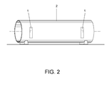
Figure 2 depicts a perspective view of a tubular section with built-in protectors. - Following there is a list of the references used in the figures:
- 1. Body.
- 2. Tubular section.
- 3. Magnet
- The present invention refers to a protector comprising a body (1) fitted with a magnet (3), which is placed on and adhered onto tubular sections (2) made of paramagnetic material, in order to avoid damages during stowing.
- As shown in
Figure 2 , the protectors are attached to the extreme zones on the side of a tubular section (2) which has already been stowed, beside which the following tubular section will be stowed (2), in such a way that the distance between the two tubular sections can be minimum and at the same time all possible damages as strokes between the tubular sections can be avoided. - The positioning of the protectors is very simple as they are fitted with a magnet (3), easily adhering onto the tubular sections (2). The power of the magnets (3) makes protectors to remain attached to the tubular sections (2) even in weather conditions with heavy wind. In this way, once the protectors are placed on the stowed tubular section (2) the worker is free to leave and begin to stow the following tubular section (2), so that there is no need for any worker to remain in the stowage area, avoiding the above described labor risks and the worker being reallocated to other tasks.
- The body (1) is made of an elastic material, e.g. high density foamed plastic, which allows high shock absorption produced during the stowage of the next adjacent tubular sections (2).
- This type of material makes it relatively easy to be able to extract the protectors and leave free the space between two tubular sections, even in cases when two tubular sections (2) remain at a distance smaller than the thickness of the body (1), being the protector compressed.
- The protectors on a tubular section (2) are removed once the following tubular section (2) has been stowed upon it, the process being repeated for the next tubular section (2) to be stowed.
- The present invention should not be limited to the described embodiment. Other configurations can be performed by experts in the field, with the present description as a starting point. As a result, the scope of the invention is defined by the following claims.
Claims (4)
- A protector for tubular sections (2) during stowage, wherein the tubular sections (2) are made of paramagnetic-material, characterized in by comprising a body (1) fitted with a magnet (3), in order to attach the protectors onto the stowed tubular sections (2) by magnetic adhesion, preventing a new stowed tubular section (2) during stowage from striking the already stowed tubular section (29).
- A protector for tubular sections (2) during stowage according to claim 1, characterized in that the body (1) is made of an elastic material.
- A protector of tubular sections (2) during stowage according to claim 2, characterized in that the elastic material is a high-density foamed plastic.
- A protector for tubular sections (2) during stowage according to claim 1, characterized in that the magnet (3) is located within the body (1), avoiding the tubular section (2) to contact the magnet (3) when locating the protector onto the tubular section (2).
Applications Claiming Priority (2)
| Application Number | Priority Date | Filing Date | Title |
|---|---|---|---|
| ES201330101A ES2488870B1 (en) | 2013-01-29 | 2013-01-29 | Protector for tubular sections during stowage |
| PCT/ES2014/070054 WO2014118412A1 (en) | 2013-01-29 | 2014-01-27 | Protector for tubular sections during stowage |
Publications (2)
| Publication Number | Publication Date |
|---|---|
| EP2952425A1 true EP2952425A1 (en) | 2015-12-09 |
| EP2952425A4 EP2952425A4 (en) | 2016-01-27 |
Family
ID=51261499
Family Applications (1)
| Application Number | Title | Priority Date | Filing Date |
|---|---|---|---|
| EP14745847.5A Withdrawn EP2952425A4 (en) | 2013-01-29 | 2014-01-27 | Protector for tubular sections during stowage |
Country Status (5)
| Country | Link |
|---|---|
| EP (1) | EP2952425A4 (en) |
| DE (1) | DE202014010698U1 (en) |
| DK (1) | DK201600048Y3 (en) |
| ES (1) | ES2488870B1 (en) |
| WO (1) | WO2014118412A1 (en) |
Cited By (1)
| Publication number | Priority date | Publication date | Assignee | Title |
|---|---|---|---|---|
| CN110282363A (en) * | 2019-06-21 | 2019-09-27 | 铜陵有色金属集团股份有限公司 | Pipeline transportation device based on tailing basis pipeline |
Family Cites Families (8)
| Publication number | Priority date | Publication date | Assignee | Title |
|---|---|---|---|---|
| US4498697A (en) * | 1983-06-02 | 1985-02-12 | Mcglone William E | Portable, positionable, locking magnetic molding tubes for vehicle protection |
| DE4133934A1 (en) * | 1991-10-14 | 1993-04-15 | Dieter Meyer | Reusable transport packing for articles - has adjustable three piece corner protectors and tension belts |
| DE19715910A1 (en) * | 1996-09-06 | 1998-10-22 | Horst Neufingerl | Building set for rigid connection of two containers |
| JP2002002809A (en) * | 2000-06-22 | 2002-01-09 | Toshiba Corp | Packaging material for use in transportation |
| JP2009120222A (en) * | 2007-11-14 | 2009-06-04 | Fuyo Astec Kk | Protective tool for article |
| WO2011069195A1 (en) * | 2009-12-09 | 2011-06-16 | The Glutt Company Pty Ltd | A cargo dunnage apparatus |
| US8822008B2 (en) * | 2010-06-22 | 2014-09-02 | Acr Group Inc. | Replaceable wear liner |
| CN102653327A (en) * | 2011-06-27 | 2012-09-05 | 何韧 | Multipurpose cargo protection pad |
-
2013
- 2013-01-29 ES ES201330101A patent/ES2488870B1/en active Active
-
2014
- 2014-01-27 WO PCT/ES2014/070054 patent/WO2014118412A1/en active Application Filing
- 2014-01-27 EP EP14745847.5A patent/EP2952425A4/en not_active Withdrawn
- 2014-01-27 DE DE202014010698.3U patent/DE202014010698U1/en not_active Expired - Lifetime
-
2016
- 2016-04-08 DK DKBA201600048U patent/DK201600048Y3/en not_active IP Right Cessation
Cited By (1)
| Publication number | Priority date | Publication date | Assignee | Title |
|---|---|---|---|---|
| CN110282363A (en) * | 2019-06-21 | 2019-09-27 | 铜陵有色金属集团股份有限公司 | Pipeline transportation device based on tailing basis pipeline |
Also Published As
| Publication number | Publication date |
|---|---|
| WO2014118412A1 (en) | 2014-08-07 |
| DK201600048U1 (en) | 2016-04-25 |
| DE202014010698U1 (en) | 2016-05-13 |
| DK201600048Y3 (en) | 2016-05-27 |
| ES2488870B1 (en) | 2015-06-29 |
| EP2952425A4 (en) | 2016-01-27 |
| ES2488870A1 (en) | 2014-08-29 |
Similar Documents
| Publication | Publication Date | Title |
|---|---|---|
| CN103472504B (en) | Aerological sounding peculiar to vessel puts ball device and preparation method thereof | |
| EP2952425A1 (en) | Protector for tubular sections during stowage | |
| CN215367102U (en) | Anti-collision rubber fender with high strength | |
| US20070175381A1 (en) | Magnetic wear device | |
| CN104061822B (en) | High-altitude suspended all-metal mesh side target for trajectory measurement | |
| CN204789093U (en) | Protection device for big triaxial test holds membrane nozzle and uses | |
| US8210007B1 (en) | Method of preventing trailer theft | |
| CN107914748B (en) | Plastic pipe fitting handling device with rain-proof function | |
| CN102263393B (en) | Ice melting device for electric pole and ice melting method thereof | |
| KR101476833B1 (en) | Unit fence module for spreading protection of oil on the sea | |
| CN204828239U (en) | Structure that prevention bolt drops | |
| CN202318090U (en) | Shockproof digital display torque wrench | |
| US10011466B1 (en) | Lifting bag device with recessed gas inlet | |
| CN206766362U (en) | A kind of SUAV recycling network | |
| CN219172637U (en) | High-strength integrally-wound inflatable rubber fender | |
| CN218698164U (en) | Ready-package storage goods locator | |
| CN220865936U (en) | Anti-collision tray | |
| CN103977532B (en) | Novel damping magnetic force barbell | |
| DE202012006499U1 (en) | Magnetic stop pin for balance weights for steel rims | |
| CN220266341U (en) | Anti-collision guardrail | |
| WO2016146129A1 (en) | A magnet protector, a method for adapting a magnet protector and use thereof | |
| CN105945022A (en) | Cleaning clamp for tube shell of travelling wave tube | |
| US9526957B2 (en) | Golf club shaft protector | |
| CN105523396B (en) | A kind of ship unloaders protective device and ship unloaders | |
| JP3202892U (en) | Concrete surface jigging jig |
Legal Events
| Date | Code | Title | Description |
|---|---|---|---|
| PUAI | Public reference made under article 153(3) epc to a published international application that has entered the european phase |
Free format text: ORIGINAL CODE: 0009012 |
|
| 17P | Request for examination filed |
Effective date: 20150729 |
|
| AK | Designated contracting states |
Kind code of ref document: A1 Designated state(s): AL AT BE BG CH CY CZ DE DK EE ES FI FR GB GR HR HU IE IS IT LI LT LU LV MC MK MT NL NO PL PT RO RS SE SI SK SM TR |
|
| AX | Request for extension of the european patent |
Extension state: BA ME |
|
| A4 | Supplementary search report drawn up and despatched |
Effective date: 20160104 |
|
| RIC1 | Information provided on ipc code assigned before grant |
Ipc: B63B 25/00 20060101AFI20151218BHEP Ipc: B65G 1/14 20060101ALI20151218BHEP |
|
| DAX | Request for extension of the european patent (deleted) | ||
| STAA | Information on the status of an ep patent application or granted ep patent |
Free format text: STATUS: THE APPLICATION IS DEEMED TO BE WITHDRAWN |
|
| 18D | Application deemed to be withdrawn |
Effective date: 20160802 |