EP2952332A1 - Système permettant de régler le fonctionnement d'une imprimante lors de l'impression d'objet tridimensionnel à l'aide d'un capteur optique - Google Patents
Système permettant de régler le fonctionnement d'une imprimante lors de l'impression d'objet tridimensionnel à l'aide d'un capteur optique Download PDFInfo
- Publication number
- EP2952332A1 EP2952332A1 EP15169738.0A EP15169738A EP2952332A1 EP 2952332 A1 EP2952332 A1 EP 2952332A1 EP 15169738 A EP15169738 A EP 15169738A EP 2952332 A1 EP2952332 A1 EP 2952332A1
- Authority
- EP
- European Patent Office
- Prior art keywords
- platen
- optical sensor
- printhead
- printer
- data
- Prior art date
- Legal status (The legal status is an assumption and is not a legal conclusion. Google has not performed a legal analysis and makes no representation as to the accuracy of the status listed.)
- Withdrawn
Links
Images

Classifications
-
- B—PERFORMING OPERATIONS; TRANSPORTING
- B29—WORKING OF PLASTICS; WORKING OF SUBSTANCES IN A PLASTIC STATE IN GENERAL
- B29C—SHAPING OR JOINING OF PLASTICS; SHAPING OF MATERIAL IN A PLASTIC STATE, NOT OTHERWISE PROVIDED FOR; AFTER-TREATMENT OF THE SHAPED PRODUCTS, e.g. REPAIRING
- B29C64/00—Additive manufacturing, i.e. manufacturing of three-dimensional [3D] objects by additive deposition, additive agglomeration or additive layering, e.g. by 3D printing, stereolithography or selective laser sintering
- B29C64/10—Processes of additive manufacturing
- B29C64/106—Processes of additive manufacturing using only liquids or viscous materials, e.g. depositing a continuous bead of viscous material
- B29C64/112—Processes of additive manufacturing using only liquids or viscous materials, e.g. depositing a continuous bead of viscous material using individual droplets, e.g. from jetting heads
-
- B—PERFORMING OPERATIONS; TRANSPORTING
- B29—WORKING OF PLASTICS; WORKING OF SUBSTANCES IN A PLASTIC STATE IN GENERAL
- B29C—SHAPING OR JOINING OF PLASTICS; SHAPING OF MATERIAL IN A PLASTIC STATE, NOT OTHERWISE PROVIDED FOR; AFTER-TREATMENT OF THE SHAPED PRODUCTS, e.g. REPAIRING
- B29C64/00—Additive manufacturing, i.e. manufacturing of three-dimensional [3D] objects by additive deposition, additive agglomeration or additive layering, e.g. by 3D printing, stereolithography or selective laser sintering
- B29C64/30—Auxiliary operations or equipment
- B29C64/386—Data acquisition or data processing for additive manufacturing
- B29C64/393—Data acquisition or data processing for additive manufacturing for controlling or regulating additive manufacturing processes
-
- B—PERFORMING OPERATIONS; TRANSPORTING
- B33—ADDITIVE MANUFACTURING TECHNOLOGY
- B33Y—ADDITIVE MANUFACTURING, i.e. MANUFACTURING OF THREE-DIMENSIONAL [3-D] OBJECTS BY ADDITIVE DEPOSITION, ADDITIVE AGGLOMERATION OR ADDITIVE LAYERING, e.g. BY 3-D PRINTING, STEREOLITHOGRAPHY OR SELECTIVE LASER SINTERING
- B33Y50/00—Data acquisition or data processing for additive manufacturing
- B33Y50/02—Data acquisition or data processing for additive manufacturing for controlling or regulating additive manufacturing processes
-
- B—PERFORMING OPERATIONS; TRANSPORTING
- B41—PRINTING; LINING MACHINES; TYPEWRITERS; STAMPS
- B41J—TYPEWRITERS; SELECTIVE PRINTING MECHANISMS, i.e. MECHANISMS PRINTING OTHERWISE THAN FROM A FORME; CORRECTION OF TYPOGRAPHICAL ERRORS
- B41J29/00—Details of, or accessories for, typewriters or selective printing mechanisms not otherwise provided for
- B41J29/38—Drives, motors, controls or automatic cut-off devices for the entire printing mechanism
- B41J29/393—Devices for controlling or analysing the entire machine ; Controlling or analysing mechanical parameters involving printing of test patterns
Definitions
- the device disclosed in this document relates to printers that produce three-dimensional objects and, more particularly, to the accurate production of objects with such printers.
- Three-dimensional printing is a process of making a three-dimensional solid object of virtually any shape from a digital model.
- One approach to three-dimensional printing uses an additive process in which one or more printheads eject successive layers of material on a substrate in different shapes.
- This approach to three-dimensional printing is also known as additive manufacturing.
- the substrate is either supported on a platform that can be moved in either one, two, or three dimensions by operation of actuators operatively connected to the platform.
- the printhead or printheads are also operatively connected to one or more actuators for controlled movement of the printhead or printheads to produce the layers that form the three-dimensional object.
- Three-dimensional printing is distinguishable from traditional object-forming techniques, which mostly rely on the removal of material from a work piece by a subtractive process, such as cutting or drilling.
- the production of a three-dimensional object with these printers can require hours or, with some objects, even days.
- One issue that arises in the production of three-dimensional objects with a three-dimensional printer is inconsistency between the actual dimensions of the printed part and the intended dimensions of the printed parts. These inconsistencies arise because the ejected ink material can flow away from its intended position when jetting onto the growing part. Other factors include thermal expansion and/or contraction of the material as hot ink is ejected onto the part and then is cooled or cured.
- one or more inkjets can deteriorate by ejecting the material at an angle, rather than normal, to the printhead, ejecting drops that are smaller or larger than an inkjet should eject, or by failing to eject any drop at all.
- Other sources of error that occur during object printing include mechanical runout, mechanical shrinkage of the ejected material, vibration, and the like.
- Dimensional accuracy of an object is currently controlled by monitoring and verifying the accuracy of the movement of the support platform and/or the printhead or printheads. The sources of error identified above, may not be detected from the monitoring of the support platform or printhead(s) movement. If one or more of these sources for error accumulate during object printing, the quality of the printed object may require the object to be scrapped. Because the print jobs can require many hours or multiple days to produce objects, this scrapping of objects can be expensive and time consuming.
- a printer capable of detecting errors in an object being produced and correcting them during printing would be advantageous.
- An apparatus that detects printing errors and compensates for the errors during a printing operation for producing a three dimensional object in a printer includes an optical sensor configured to generate data corresponding to edges of a top layer of material ejected onto a platen, and a controller operatively connected to the optical sensor, the controller being configured to generate raster image data for layers to be printed to form an object on the platen, and to modify raster image data for layers to be printed with reference to the data received from the optical sensor to compensate for errors in the ejection of the material onto the platen from the ejectors in the printhead.
- a printer that incorporates the apparatus that detects printing errors and compensates for the error during a printing operation that produces a three dimensional object includes a platen, a printhead configured with ejectors to eject material onto the platen, an optical sensor configured to generate data corresponding to edges of a top layer of the material ejected onto the platen, and a controller operatively connected to the optical sensor and the printhead, the controller being configured to generate raster image data for layers to be printed to form an object on the platen, to operate the printhead to eject material onto the platen with reference to the raster image data for the layers, and to modify raster image data for layers to be printed with reference to data received from the optical sensor to compensate for errors in the ejection of the material from the ejectors in the printhead.
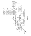
- FIG. 3 shows a configuration of components in a prior art printer 300, which produces a three-dimensional object or part 26.
- the printer 300 includes a support platen 14 on which one or more printheads 22 for an object or part 26.
- the printhead(s) are configured to eject one or more types of build material and support material to form the part 26. These materials can require curing so the printer 300 includes a curing device 30.
- the curing device 30 is an ultraviolet (UV) radiation source.
- a planerizer can be include to normalize the height of material in a layer formed on the object by the one or more printheads 22.
- the printhead(s) 22 and support platen 14 are configured with actuators 24 and the like for movement.
- the support platen 14 is configured for movement along an X axis and the printhead(s) is configured to move along a Z axis, although the platen 14 could also be configured for movement along the Z axis.
- the movement of the platen 14 and the printhead(s) 22 are coordinated by a controller 34, which is operatively connected to the actuators 24 with which the platen and printhead(s) are configured for movement.
- the printhead(s) 22 are wider along a Y axis than the part being built. Consequently, movement along the Y axis is not required.
- the printhead(s) are not wider than the part so the platen 14 and/or printhead(s) 22 are configured for movement along the Y axis.
- the resolution of the inkjets in the printheads is less than the resolution required for the part. In these embodiments movement is also needed along the Y axis to build up a layer at the resolution required for the part.
- process direction refers to movement along one axis in the surface of the support platen 14
- cross-process direction refers to movement along an axis in the support platen 14 that is orthogonal to the process direction axis in that platen.
- FIG. 3 refer to the X and Y axes. While the platen 14 of FIG. 3 is shown as a planar member, other embodiments of three-dimensional printers include platens that are circular discs, an inner wall of a rotating cylinder or drum, or a rotating cone. The movement of the platen and the printhead(s) in these printers can be described with polar coordinates.
- a three-dimensional raster processor 38 receives a file 40 of three-dimensional data of the part to be produced. These three-dimensional part data can be contained in a computer-aided design (CAD) file, for example.
- the processor 38 uses these data to generate a raster data file 42, which contains data that correspond to thin layers of the part.
- the printhead driver 46 receives the raster data file 42 and generates pixelated data that are used to operate the ejectors in the printhead(s) 22 for the ejection of building and support material onto the support platen 14 to form the part layer by layer.
- the printhead driver 46 and the controller 34 generate signals to coordinate the movement of the platen 14 and the printhead(s) 22 with the operation of the ejectors in the printhead.
- the printer 100 includes a platen 14, printhead(s) 22, curing device 30, a controller 34, a raster image processor 38 that generates a raster data file 42, and a printhead driver 46. Additionally, the printer 200 also includes an optical sensor 50 and a compensation processor 54.
- the optical sensor can be a optical contrast sensor having a one dimensional or two dimensional array of photodetectors configured with an illumination source.
- the illumination source directs light at a layer of an object and the array of photodetectors are positioned to receive reflected light from the illuminated layer. Because the materials reflect light differently, the photodetectors receive more light from one of the materials more than they receive from the other material.
- the photodetectors generate electrical signals, which are converted by an A/D converter or the like, into image data that can be analyzed by a controller.
- the optical contrast between the two materials can be used to detect edges of the layer and between the materials.
- the optical sensor can be configured to generate topographical data of the part 26 along with measurements of features in the topographical data.
- a topographical optical sensor can be a blue laser sensor available from Keyence Corporation of America, Itasca, IL in the LJ-V7000 series of two dimensional and three-dimensional laser measurement systems. This sensor can generate measurements of the material drops as well as positional data regarding the location of the drops or features formed by the build material drops. Even in embodiments that eject both support and build material and use a planerizer, a topographical optical sensor can be useful to verify the height trimming of the planerizer.
- the data from the optical sensor are provided in a data file 52 to the compensation processor 54.
- the compensation processor 54 generates positional data for edges from the image data of an optical contrast sensor or receives measurement data from a topographical sensor. These data are compared with the data in the raster data file 42 for the layer previously printed and generates the differences between these data.
- the compensation processor 54 uses these differences to modify the raster data for the next layer to be printed.
- the printhead driver 46 receives these modified raster data 48 to generate the pixelated data for operating the ejectors in the printhead and to control movement of the platen 14 and the printhead(s) 22. In this manner, the sensor 34 measures the errors occurring in a previously printed layer and the compensation processor 54 adjust data for forming a next layer with these measured error data to compensate for the measured errors and keep the part within tolerances.
- the diameter of the circle of a cross section at any height through the material can be obtained from the image data received from an optical contrast sensor or determined with reference to measurement data from a topographical optical sensor.
- the edge of the layer is determined after each layer is printed from the optical contrast in the image data between the support material and the build material. If the diameter of the circle that best fits the measured region is larger than the intended diameter of the part for this layer, then the digital image of the next layer is decreased so that the measured diameter matches the intended diameter. Under some conditions, local changes in heating of the part may cause the perimeter to deviate from a circle.
- the part may start to show a bulge at some location in the circle.
- the raster data is adjusted to form a divot at the bulge location in the next layer so that the intended circular shape can be maintained as the part is built up.
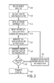
- FIG. 2 A method of operating a printer that compensates for measured errors in three-dimensional objects during their printing is shown in FIG. 2 .
- statements that a process is performing some task or function refers to a controller or general purpose processor executing programmed instructions stored in a memory operatively connected to the controller or processor to manipulate data or to operate one or more components in the printer to perform the task or function.
- the controllers 34, 38, and 54 noted above can be such a controller or processor.
- these controllers can be implemented with more than one processor and associated circuitry and components, each of which is configured to form one or more tasks or functions described herein.
- the raster image processor receives a data file of three-dimensional data of a part (block 204).
- the raster image processor 54 generates raster image data for the layers to be printed to form the part (block 208).
- the sensor difference data is initialized to an origin value (block 212).
- the compensation processor 54 passes the raster image data for the first layer through to the printhead driver 46 (block 216) and the driver generates the pixelated data for operating the ejectors in the printhead and controlling movement of the platen 14 and the printhead(s) 22 (block 220).
- the optical sensor After one or more layers are printed, the optical sensor generates data corresponding to the edges in the top layer (block 224). These data, as noted above, can be optical contrast image data or topographical and measurement data.
- the raster image processor 54 determines if another layer is to be printed (block 228), and if another layer is to be printed, the processor compares the data corresponding to the edges with the data in the raster data file 42 for the layer previously printed and generates the differences between these data (block 232).
- the compensation processor 54 uses these differences to modify the raster data for the next layer to be printed (block 216).
- the compensation processor 54 changes the pixels in the raster image data at the position of the bulging edge in the next layer to be printed to support material pixels.
- compensation processor 54 converts the support material pixels in a next layer to be printed to build material pixels.
- the printhead driver 46 receives these modified raster data to generate the pixelated data for operating the ejectors in the printhead and controlling movement of the platen 14 and the printhead(s) 22 (block 220). This compensation scheme continues until no more layers are to be printed (block 228) and the process terminates (block 240).
Applications Claiming Priority (1)
| Application Number | Priority Date | Filing Date | Title |
|---|---|---|---|
| US14/298,232 US9327537B2 (en) | 2014-06-06 | 2014-06-06 | System for adjusting operation of a printer during three-dimensional object printing using an optical sensor |
Publications (1)
| Publication Number | Publication Date |
|---|---|
| EP2952332A1 true EP2952332A1 (fr) | 2015-12-09 |
Family
ID=53502418
Family Applications (1)
| Application Number | Title | Priority Date | Filing Date |
|---|---|---|---|
| EP15169738.0A Withdrawn EP2952332A1 (fr) | 2014-06-06 | 2015-05-28 | Système permettant de régler le fonctionnement d'une imprimante lors de l'impression d'objet tridimensionnel à l'aide d'un capteur optique |
Country Status (5)
| Country | Link |
|---|---|
| US (1) | US9327537B2 (fr) |
| EP (1) | EP2952332A1 (fr) |
| JP (1) | JP6404770B2 (fr) |
| KR (1) | KR102234906B1 (fr) |
| CN (1) | CN105291428B (fr) |
Cited By (6)
| Publication number | Priority date | Publication date | Assignee | Title |
|---|---|---|---|---|
| CN107229430A (zh) * | 2016-03-23 | 2017-10-03 | 深圳维示泰克技术有限公司 | 一种应用于3d打印的自动调平方法及其调平设备 |
| EP3299146A1 (fr) * | 2016-09-21 | 2018-03-28 | Seiko Epson Corporation | Appareil de modélisation en trois dimensions, et procédé de production |
| KR20180114552A (ko) * | 2016-03-09 | 2018-10-18 | 어플라이드 머티어리얼스, 인코포레이티드 | 적층 제조에서 제조된 형상들의 보정 |
| US10882160B2 (en) | 2017-05-25 | 2021-01-05 | Applied Materials, Inc. | Correction of fabricated shapes in additive manufacturing using sacrificial material |
| US10967482B2 (en) | 2017-05-25 | 2021-04-06 | Applied Materials, Inc. | Fabrication of polishing pad by additive manufacturing onto mold |
| WO2023129665A1 (fr) * | 2021-12-31 | 2023-07-06 | Evolve Additive Solutions, Inc. | Procédé et article de fabrication additive avec commandes de construction basées sur une image |
Families Citing this family (28)
| Publication number | Priority date | Publication date | Assignee | Title |
|---|---|---|---|---|
| DE102013217422A1 (de) * | 2013-09-02 | 2015-03-05 | Carl Zeiss Industrielle Messtechnik Gmbh | Koordinatenmessgerät und Verfahren zur Vermessung und mindestens teilweisen Erzeugung eines Werkstücks |
| US10252466B2 (en) | 2014-07-28 | 2019-04-09 | Massachusetts Institute Of Technology | Systems and methods of machine vision assisted additive fabrication |
| US10786948B2 (en) | 2014-11-18 | 2020-09-29 | Sigma Labs, Inc. | Multi-sensor quality inference and control for additive manufacturing processes |
| WO2016165016A1 (fr) * | 2015-04-14 | 2016-10-20 | Magor Communications Corporation | Panorama de synthèses de vue |
| US10005229B2 (en) | 2015-08-31 | 2018-06-26 | Xerox Corporation | System for using optical sensor focus to identify feature heights on objects being produced in a three-dimensional object printer |
| US10207489B2 (en) * | 2015-09-30 | 2019-02-19 | Sigma Labs, Inc. | Systems and methods for additive manufacturing operations |
| US10011078B2 (en) | 2015-10-01 | 2018-07-03 | Xerox Corporation | System for using multiple optical sensor arrays to measure features on objects produced in a three-dimensional object printer |
| US9993977B2 (en) | 2015-10-01 | 2018-06-12 | Xerox Corporation | System for using an optical sensor array to monitor color fidelity in objects produced by a three-dimensional object printer |
| US11141919B2 (en) | 2015-12-09 | 2021-10-12 | Holo, Inc. | Multi-material stereolithographic three dimensional printing |
| US10259164B2 (en) * | 2016-06-22 | 2019-04-16 | Massachusetts Institute Of Technology | Methods and apparatus for 3D printing of point cloud data |
| JP6765666B2 (ja) * | 2016-07-12 | 2020-10-07 | 学校法人慶應義塾 | 立体物製造装置、立体物製造方法及びプログラム |
| WO2018039614A1 (fr) * | 2016-08-26 | 2018-03-01 | Massachusetts Institute Of Technology | Systèmes, dispositifs et procédés d'impression tridimensionnelle à base de jet d'encre |
| JP6827741B2 (ja) | 2016-08-31 | 2021-02-10 | キヤノン株式会社 | 情報処理装置、制御方法、およびプログラム |
| EP3554798B1 (fr) | 2016-12-16 | 2020-12-02 | Massachusetts Institute of Technology | Dépôt de matériau adaptatif pour fabrication additive |
| US10953647B2 (en) | 2017-01-06 | 2021-03-23 | International Business Machines Corporation | Methods and systems for detecting and rectifying faults in 3D printing processes |
| CN106863779A (zh) * | 2017-03-06 | 2017-06-20 | 佛山美立三维科技有限公司 | 一种基于光固化技术的表面纹理处理方法 |
| US9925726B1 (en) * | 2017-04-03 | 2018-03-27 | Xerox Corporation | Apparatus for holding three-dimensional (3-D) objects during printing thereon |
| US9975327B1 (en) * | 2017-05-18 | 2018-05-22 | Xerox Corporation | System and method for adjusting printhead operations in a direct-to-object printer having a fixed printhead array |
| CN107053663B (zh) * | 2017-06-27 | 2019-11-19 | 上海联泰三维科技有限公司 | 光学系统、照射控制方法及所适用的3d打印设备 |
| CN111051045B (zh) * | 2017-09-05 | 2022-06-03 | Slm方案集团股份公司 | 通过移动生产单元生产大工件的设备和方法 |
| EP3473412A1 (fr) * | 2017-10-20 | 2019-04-24 | CL Schutzrechtsverwaltungs GmbH | Appareil et procédé de fabrication additive d'objets tridimensionnels |
| US20200376775A1 (en) * | 2018-02-15 | 2020-12-03 | Ddm Systems, Inc. | Casting techniques, casts, and three-dimensional printing systems and methods |
| WO2019206903A1 (fr) | 2018-04-23 | 2019-10-31 | Carl Zeiss Industrial Metrology, Llc | Procédé et agencement pour produire une pièce à travailler à l'aide d'une commande en boucle fermée adaptative de techniques de fabrication additive |
| WO2020139858A1 (fr) * | 2018-12-26 | 2020-07-02 | Holo, Inc. | Capteurs pour systèmes et méthodes d'impression tridimensionnelle |
| WO2021073717A1 (fr) | 2019-10-14 | 2021-04-22 | Wacker Chemie Ag | Dispositif d'impression 3d et procédé de production d'objets avec une qualité d'impression accrue |
| US11491732B2 (en) * | 2020-03-09 | 2022-11-08 | Xerox Corporation | Three-dimensional (3D) object printing system that compensates for misregistration |
| WO2021262819A1 (fr) * | 2020-06-25 | 2021-12-30 | Holo, Inc. | Procédés et systèmes de gestion d'impression tridimensionnelle |
| CN115447137A (zh) * | 2022-09-29 | 2022-12-09 | 哈尔滨工程大学 | 一种光固化3d打印装置以及打印方法 |
Citations (2)
| Publication number | Priority date | Publication date | Assignee | Title |
|---|---|---|---|---|
| US20080192074A1 (en) * | 2003-08-29 | 2008-08-14 | Martine Dubois | Method and Device for the Production of a Three-Dimensional Multi-Material Component by Means of Ink-Jet-Type Printing |
| US20110273502A1 (en) * | 2010-05-04 | 2011-11-10 | Xerox Corporation | Method And System To Compensate For Process Direction Misalignment Of Printheads In A Continuous Web Inkjet Printer |
Family Cites Families (5)
| Publication number | Priority date | Publication date | Assignee | Title |
|---|---|---|---|---|
| US5490962A (en) | 1993-10-18 | 1996-02-13 | Massachusetts Institute Of Technology | Preparation of medical devices by solid free-form fabrication methods |
| US6270335B2 (en) * | 1995-09-27 | 2001-08-07 | 3D Systems, Inc. | Selective deposition modeling method and apparatus for forming three-dimensional objects and supports |
| US6007318A (en) | 1996-12-20 | 1999-12-28 | Z Corporation | Method and apparatus for prototyping a three-dimensional object |
| ES2262851T3 (es) | 2001-10-29 | 2006-12-01 | Therics, Inc. | Un sistema y metodo para compresion unaxial de un articulo, tal como una forma dosificadora estampada tridimensionalmente. |
| US8666142B2 (en) * | 2008-11-18 | 2014-03-04 | Global Filtration Systems | System and method for manufacturing |
-
2014
- 2014-06-06 US US14/298,232 patent/US9327537B2/en active Active
-
2015
- 2015-05-21 JP JP2015103461A patent/JP6404770B2/ja active Active
- 2015-05-25 CN CN201510272001.6A patent/CN105291428B/zh active Active
- 2015-05-26 KR KR1020150072795A patent/KR102234906B1/ko active IP Right Grant
- 2015-05-28 EP EP15169738.0A patent/EP2952332A1/fr not_active Withdrawn
Patent Citations (2)
| Publication number | Priority date | Publication date | Assignee | Title |
|---|---|---|---|---|
| US20080192074A1 (en) * | 2003-08-29 | 2008-08-14 | Martine Dubois | Method and Device for the Production of a Three-Dimensional Multi-Material Component by Means of Ink-Jet-Type Printing |
| US20110273502A1 (en) * | 2010-05-04 | 2011-11-10 | Xerox Corporation | Method And System To Compensate For Process Direction Misalignment Of Printheads In A Continuous Web Inkjet Printer |
Cited By (17)
| Publication number | Priority date | Publication date | Assignee | Title |
|---|---|---|---|---|
| US11154961B2 (en) | 2016-03-09 | 2021-10-26 | Applied Materials, Inc. | Correction of fabricated shapes in additive manufacturing |
| KR20210151238A (ko) * | 2016-03-09 | 2021-12-13 | 어플라이드 머티어리얼스, 인코포레이티드 | 적층 제조에서 제조된 형상들의 보정 |
| US11597054B2 (en) | 2016-03-09 | 2023-03-07 | Applied Materials, Inc. | Correction of fabricated shapes in additive manufacturing |
| EP3427288A4 (fr) * | 2016-03-09 | 2019-11-20 | Applied Materials, Inc. | Correction de formes fabriquées dans une fabrication additive |
| EP3869538A1 (fr) * | 2016-03-09 | 2021-08-25 | Applied Materials, Inc. | Correction de formes fabriquées dans une fabrication additive |
| US10537973B2 (en) | 2016-03-09 | 2020-01-21 | Applied Materials, Inc. | Correction of fabricated shapes in additive manufacturing |
| KR20180114552A (ko) * | 2016-03-09 | 2018-10-18 | 어플라이드 머티어리얼스, 인코포레이티드 | 적층 제조에서 제조된 형상들의 보정 |
| CN107229430A (zh) * | 2016-03-23 | 2017-10-03 | 深圳维示泰克技术有限公司 | 一种应用于3d打印的自动调平方法及其调平设备 |
| CN107229430B (zh) * | 2016-03-23 | 2021-04-27 | 深圳维示泰克技术有限公司 | 一种应用于3d打印的自动调平方法及其调平设备 |
| US10589501B2 (en) | 2016-09-21 | 2020-03-17 | Seiko Epson Corporation | Three-dimensional modeling apparatus, production method, and computer program |
| EP3299146A1 (fr) * | 2016-09-21 | 2018-03-28 | Seiko Epson Corporation | Appareil de modélisation en trois dimensions, et procédé de production |
| US11084143B2 (en) | 2017-05-25 | 2021-08-10 | Applied Materials, Inc. | Correction of fabricated shapes in additive manufacturing using modified edge |
| US10882160B2 (en) | 2017-05-25 | 2021-01-05 | Applied Materials, Inc. | Correction of fabricated shapes in additive manufacturing using sacrificial material |
| US10967482B2 (en) | 2017-05-25 | 2021-04-06 | Applied Materials, Inc. | Fabrication of polishing pad by additive manufacturing onto mold |
| US11059149B2 (en) | 2017-05-25 | 2021-07-13 | Applied Materials, Inc. | Correction of fabricated shapes in additive manufacturing using initial layer |
| US11642757B2 (en) | 2017-05-25 | 2023-05-09 | Applied Materials, Inc. | Using sacrificial material in additive manufacturing of polishing pads |
| WO2023129665A1 (fr) * | 2021-12-31 | 2023-07-06 | Evolve Additive Solutions, Inc. | Procédé et article de fabrication additive avec commandes de construction basées sur une image |
Also Published As
| Publication number | Publication date |
|---|---|
| KR20150140565A (ko) | 2015-12-16 |
| KR102234906B1 (ko) | 2021-03-31 |
| JP2015229349A (ja) | 2015-12-21 |
| US20150352872A1 (en) | 2015-12-10 |
| CN105291428A (zh) | 2016-02-03 |
| JP6404770B2 (ja) | 2018-10-17 |
| CN105291428B (zh) | 2018-06-05 |
| US9327537B2 (en) | 2016-05-03 |
Similar Documents
| Publication | Publication Date | Title |
|---|---|---|
| US9327537B2 (en) | System for adjusting operation of a printer during three-dimensional object printing using an optical sensor | |
| US9738032B2 (en) | System for controlling operation of a printer during three-dimensional object printing with reference to a distance from the surface of object | |
| US9446556B2 (en) | System for compensating for drop volume variation during three-dimensional printing of an object | |
| US9205691B1 (en) | System for compensating for drop volume variation between inkjets in a three-dimensional object printer | |
| US10052823B2 (en) | System and method for test pattern formation during three-dimensional object printing | |
| US9908289B2 (en) | System and method for correcting object defects formed by a three-dimensional object printing system | |
| US11565475B2 (en) | Method and system for operating a metal drop ejecting three-dimensional (3D) object printer to compensate for geometric variations that occur during an additive manufacturing process | |
| US9597839B2 (en) | System for adjusting operation of a printer during three-dimensional object printing to compensate for errors in object formation | |
| US9731452B2 (en) | Three dimensional printer and method for adjusting working coordinate of platform thereof | |
| US10183445B2 (en) | Method for using multiple optical sensor arrays to measure features on objects produced in a three-dimensional object printer | |
| KR102269950B1 (ko) | 입체물 인쇄 시스템 및 입체물 인쇄 방법 | |
| KR20210105400A (ko) | 기판 정렬 요소들 및 프린트 영역 정렬 요소들을 이용한 토출 제어 | |
| EP3800539A1 (fr) | Procédé et système pour faire fonctionner une imprimante d'objets en trois dimensions (3d) à éjection de gouttes de métal pour compenser les variations de taille de goutte | |
| US9833950B2 (en) | System and method for inoperative inkjet detection in a printer of three-dimensional objects | |
| CN103832104A (zh) | 在3d表面上打印涂层的方法和系统 | |
| EP3744505B1 (fr) | Procédé d'étalonnage d'un appareil de production d'un objet au moyen de fabrication additive et appareil pour le procédé | |
| US10005303B2 (en) | System for detecting inoperative inkjets in three-dimensional object printing using a profilometer and predetermined test pattern printing | |
| US9168772B2 (en) | System for detecting inoperative inkjets in printheads ejecting clear ink using three dimensional imaging | |
| JP2021138138A (ja) | 位置ずれを補償する3次元(3d)オブジェクト印刷システム | |
| US11141968B2 (en) | Method for ejector to ejector pixel height normalization | |
| EP3233426B1 (fr) | Détection d'une anomalie dans une imprimante 3d | |
| JP2006240068A (ja) | インクジェット記録装置 | |
| US20170279389A1 (en) | Support structure adjustment |
Legal Events
| Date | Code | Title | Description |
|---|---|---|---|
| PUAI | Public reference made under article 153(3) epc to a published international application that has entered the european phase |
Free format text: ORIGINAL CODE: 0009012 |
|
| AK | Designated contracting states |
Kind code of ref document: A1 Designated state(s): AL AT BE BG CH CY CZ DE DK EE ES FI FR GB GR HR HU IE IS IT LI LT LU LV MC MK MT NL NO PL PT RO RS SE SI SK SM TR |
|
| AX | Request for extension of the european patent |
Extension state: BA ME |
|
| 17P | Request for examination filed |
Effective date: 20160609 |
|
| RBV | Designated contracting states (corrected) |
Designated state(s): AL AT BE BG CH CY CZ DE DK EE ES FI FR GB GR HR HU IE IS IT LI LT LU LV MC MK MT NL NO PL PT RO RS SE SI SK SM TR |
|
| 17Q | First examination report despatched |
Effective date: 20170202 |
|
| STAA | Information on the status of an ep patent application or granted ep patent |
Free format text: STATUS: THE APPLICATION IS DEEMED TO BE WITHDRAWN |
|
| 18D | Application deemed to be withdrawn |
Effective date: 20170613 |