EP2952307B1 - Vorrichtung und verfahren zum aufbringen eines kantenbandes auf eine schmalseite eines werkstücks - Google Patents
Vorrichtung und verfahren zum aufbringen eines kantenbandes auf eine schmalseite eines werkstücks Download PDFInfo
- Publication number
- EP2952307B1 EP2952307B1 EP15001075.9A EP15001075A EP2952307B1 EP 2952307 B1 EP2952307 B1 EP 2952307B1 EP 15001075 A EP15001075 A EP 15001075A EP 2952307 B1 EP2952307 B1 EP 2952307B1
- Authority
- EP
- European Patent Office
- Prior art keywords
- radiation
- edge
- laser
- edge strip
- elements
- Prior art date
- Legal status (The legal status is an assumption and is not a legal conclusion. Google has not performed a legal analysis and makes no representation as to the accuracy of the status listed.)
- Active
Links
Images


Classifications
-
- B—PERFORMING OPERATIONS; TRANSPORTING
- B27—WORKING OR PRESERVING WOOD OR SIMILAR MATERIAL; NAILING OR STAPLING MACHINES IN GENERAL
- B27D—WORKING VENEER OR PLYWOOD
- B27D5/00—Other working of veneer or plywood specially adapted to veneer or plywood
- B27D5/003—Other working of veneer or plywood specially adapted to veneer or plywood securing a veneer strip to a panel edge
-
- B—PERFORMING OPERATIONS; TRANSPORTING
- B23—MACHINE TOOLS; METAL-WORKING NOT OTHERWISE PROVIDED FOR
- B23K—SOLDERING OR UNSOLDERING; WELDING; CLADDING OR PLATING BY SOLDERING OR WELDING; CUTTING BY APPLYING HEAT LOCALLY, e.g. FLAME CUTTING; WORKING BY LASER BEAM
- B23K26/00—Working by laser beam, e.g. welding, cutting or boring
- B23K26/02—Positioning or observing the workpiece, e.g. with respect to the point of impact; Aligning, aiming or focusing the laser beam
- B23K26/06—Shaping the laser beam, e.g. by masks or multi-focusing
- B23K26/0604—Shaping the laser beam, e.g. by masks or multi-focusing by a combination of beams
- B23K26/0608—Shaping the laser beam, e.g. by masks or multi-focusing by a combination of beams in the same heat affected zone [HAZ]
-
- B—PERFORMING OPERATIONS; TRANSPORTING
- B23—MACHINE TOOLS; METAL-WORKING NOT OTHERWISE PROVIDED FOR
- B23K—SOLDERING OR UNSOLDERING; WELDING; CLADDING OR PLATING BY SOLDERING OR WELDING; CUTTING BY APPLYING HEAT LOCALLY, e.g. FLAME CUTTING; WORKING BY LASER BEAM
- B23K26/00—Working by laser beam, e.g. welding, cutting or boring
- B23K26/08—Devices involving relative movement between laser beam and workpiece
- B23K26/083—Devices involving movement of the workpiece in at least one axial direction
- B23K26/0838—Devices involving movement of the workpiece in at least one axial direction by using an endless conveyor belt
- B23K26/0846—Devices involving movement of the workpiece in at least one axial direction by using an endless conveyor belt for moving elongated workpieces longitudinally, e.g. wire or strip material
-
- B—PERFORMING OPERATIONS; TRANSPORTING
- B23—MACHINE TOOLS; METAL-WORKING NOT OTHERWISE PROVIDED FOR
- B23K—SOLDERING OR UNSOLDERING; WELDING; CLADDING OR PLATING BY SOLDERING OR WELDING; CUTTING BY APPLYING HEAT LOCALLY, e.g. FLAME CUTTING; WORKING BY LASER BEAM
- B23K26/00—Working by laser beam, e.g. welding, cutting or boring
- B23K26/20—Bonding
- B23K26/21—Bonding by welding
- B23K26/24—Seam welding
- B23K26/244—Overlap seam welding
-
- B—PERFORMING OPERATIONS; TRANSPORTING
- B23—MACHINE TOOLS; METAL-WORKING NOT OTHERWISE PROVIDED FOR
- B23K—SOLDERING OR UNSOLDERING; WELDING; CLADDING OR PLATING BY SOLDERING OR WELDING; CUTTING BY APPLYING HEAT LOCALLY, e.g. FLAME CUTTING; WORKING BY LASER BEAM
- B23K26/00—Working by laser beam, e.g. welding, cutting or boring
- B23K26/20—Bonding
- B23K26/32—Bonding taking account of the properties of the material involved
- B23K26/323—Bonding taking account of the properties of the material involved involving parts made of dissimilar metallic material
-
- B—PERFORMING OPERATIONS; TRANSPORTING
- B23—MACHINE TOOLS; METAL-WORKING NOT OTHERWISE PROVIDED FOR
- B23K—SOLDERING OR UNSOLDERING; WELDING; CLADDING OR PLATING BY SOLDERING OR WELDING; CUTTING BY APPLYING HEAT LOCALLY, e.g. FLAME CUTTING; WORKING BY LASER BEAM
- B23K26/00—Working by laser beam, e.g. welding, cutting or boring
- B23K26/20—Bonding
- B23K26/32—Bonding taking account of the properties of the material involved
- B23K26/324—Bonding taking account of the properties of the material involved involving non-metallic parts
-
- B—PERFORMING OPERATIONS; TRANSPORTING
- B29—WORKING OF PLASTICS; WORKING OF SUBSTANCES IN A PLASTIC STATE IN GENERAL
- B29C—SHAPING OR JOINING OF PLASTICS; SHAPING OF MATERIAL IN A PLASTIC STATE, NOT OTHERWISE PROVIDED FOR; AFTER-TREATMENT OF THE SHAPED PRODUCTS, e.g. REPAIRING
- B29C63/00—Lining or sheathing, i.e. applying preformed layers or sheathings of plastics; Apparatus therefor
- B29C63/0026—Lining or sheathing, i.e. applying preformed layers or sheathings of plastics; Apparatus therefor an edge face with strip material, e.g. a panel edge
-
- B—PERFORMING OPERATIONS; TRANSPORTING
- B29—WORKING OF PLASTICS; WORKING OF SUBSTANCES IN A PLASTIC STATE IN GENERAL
- B29C—SHAPING OR JOINING OF PLASTICS; SHAPING OF MATERIAL IN A PLASTIC STATE, NOT OTHERWISE PROVIDED FOR; AFTER-TREATMENT OF THE SHAPED PRODUCTS, e.g. REPAIRING
- B29C63/00—Lining or sheathing, i.e. applying preformed layers or sheathings of plastics; Apparatus therefor
- B29C63/0065—Heat treatment
-
- B—PERFORMING OPERATIONS; TRANSPORTING
- B29—WORKING OF PLASTICS; WORKING OF SUBSTANCES IN A PLASTIC STATE IN GENERAL
- B29C—SHAPING OR JOINING OF PLASTICS; SHAPING OF MATERIAL IN A PLASTIC STATE, NOT OTHERWISE PROVIDED FOR; AFTER-TREATMENT OF THE SHAPED PRODUCTS, e.g. REPAIRING
- B29C65/00—Joining or sealing of preformed parts, e.g. welding of plastics materials; Apparatus therefor
- B29C65/02—Joining or sealing of preformed parts, e.g. welding of plastics materials; Apparatus therefor by heating, with or without pressure
- B29C65/14—Joining or sealing of preformed parts, e.g. welding of plastics materials; Apparatus therefor by heating, with or without pressure using wave energy, i.e. electromagnetic radiation, or particle radiation
- B29C65/16—Laser beams
- B29C65/1629—Laser beams characterised by the way of heating the interface
- B29C65/1632—Laser beams characterised by the way of heating the interface direct heating the surfaces to be joined
-
- B—PERFORMING OPERATIONS; TRANSPORTING
- B29—WORKING OF PLASTICS; WORKING OF SUBSTANCES IN A PLASTIC STATE IN GENERAL
- B29C—SHAPING OR JOINING OF PLASTICS; SHAPING OF MATERIAL IN A PLASTIC STATE, NOT OTHERWISE PROVIDED FOR; AFTER-TREATMENT OF THE SHAPED PRODUCTS, e.g. REPAIRING
- B29C65/00—Joining or sealing of preformed parts, e.g. welding of plastics materials; Apparatus therefor
- B29C65/02—Joining or sealing of preformed parts, e.g. welding of plastics materials; Apparatus therefor by heating, with or without pressure
- B29C65/14—Joining or sealing of preformed parts, e.g. welding of plastics materials; Apparatus therefor by heating, with or without pressure using wave energy, i.e. electromagnetic radiation, or particle radiation
- B29C65/16—Laser beams
- B29C65/1629—Laser beams characterised by the way of heating the interface
- B29C65/1654—Laser beams characterised by the way of heating the interface scanning at least one of the parts to be joined
- B29C65/1658—Laser beams characterised by the way of heating the interface scanning at least one of the parts to be joined scanning once, e.g. contour laser welding
-
- B—PERFORMING OPERATIONS; TRANSPORTING
- B29—WORKING OF PLASTICS; WORKING OF SUBSTANCES IN A PLASTIC STATE IN GENERAL
- B29C—SHAPING OR JOINING OF PLASTICS; SHAPING OF MATERIAL IN A PLASTIC STATE, NOT OTHERWISE PROVIDED FOR; AFTER-TREATMENT OF THE SHAPED PRODUCTS, e.g. REPAIRING
- B29C65/00—Joining or sealing of preformed parts, e.g. welding of plastics materials; Apparatus therefor
- B29C65/02—Joining or sealing of preformed parts, e.g. welding of plastics materials; Apparatus therefor by heating, with or without pressure
- B29C65/14—Joining or sealing of preformed parts, e.g. welding of plastics materials; Apparatus therefor by heating, with or without pressure using wave energy, i.e. electromagnetic radiation, or particle radiation
- B29C65/16—Laser beams
- B29C65/1629—Laser beams characterised by the way of heating the interface
- B29C65/1664—Laser beams characterised by the way of heating the interface making use of several radiators
-
- B—PERFORMING OPERATIONS; TRANSPORTING
- B29—WORKING OF PLASTICS; WORKING OF SUBSTANCES IN A PLASTIC STATE IN GENERAL
- B29C—SHAPING OR JOINING OF PLASTICS; SHAPING OF MATERIAL IN A PLASTIC STATE, NOT OTHERWISE PROVIDED FOR; AFTER-TREATMENT OF THE SHAPED PRODUCTS, e.g. REPAIRING
- B29C65/00—Joining or sealing of preformed parts, e.g. welding of plastics materials; Apparatus therefor
- B29C65/02—Joining or sealing of preformed parts, e.g. welding of plastics materials; Apparatus therefor by heating, with or without pressure
- B29C65/14—Joining or sealing of preformed parts, e.g. welding of plastics materials; Apparatus therefor by heating, with or without pressure using wave energy, i.e. electromagnetic radiation, or particle radiation
- B29C65/16—Laser beams
- B29C65/1629—Laser beams characterised by the way of heating the interface
- B29C65/1674—Laser beams characterised by the way of heating the interface making use of laser diodes
-
- B—PERFORMING OPERATIONS; TRANSPORTING
- B29—WORKING OF PLASTICS; WORKING OF SUBSTANCES IN A PLASTIC STATE IN GENERAL
- B29C—SHAPING OR JOINING OF PLASTICS; SHAPING OF MATERIAL IN A PLASTIC STATE, NOT OTHERWISE PROVIDED FOR; AFTER-TREATMENT OF THE SHAPED PRODUCTS, e.g. REPAIRING
- B29C66/00—General aspects of processes or apparatus for joining preformed parts
- B29C66/01—General aspects dealing with the joint area or with the area to be joined
- B29C66/05—Particular design of joint configurations
- B29C66/10—Particular design of joint configurations particular design of the joint cross-sections
- B29C66/11—Joint cross-sections comprising a single joint-segment, i.e. one of the parts to be joined comprising a single joint-segment in the joint cross-section
- B29C66/112—Single lapped joints
-
- B—PERFORMING OPERATIONS; TRANSPORTING
- B29—WORKING OF PLASTICS; WORKING OF SUBSTANCES IN A PLASTIC STATE IN GENERAL
- B29C—SHAPING OR JOINING OF PLASTICS; SHAPING OF MATERIAL IN A PLASTIC STATE, NOT OTHERWISE PROVIDED FOR; AFTER-TREATMENT OF THE SHAPED PRODUCTS, e.g. REPAIRING
- B29C66/00—General aspects of processes or apparatus for joining preformed parts
- B29C66/01—General aspects dealing with the joint area or with the area to be joined
- B29C66/05—Particular design of joint configurations
- B29C66/10—Particular design of joint configurations particular design of the joint cross-sections
- B29C66/11—Joint cross-sections comprising a single joint-segment, i.e. one of the parts to be joined comprising a single joint-segment in the joint cross-section
- B29C66/114—Single butt joints
-
- B—PERFORMING OPERATIONS; TRANSPORTING
- B29—WORKING OF PLASTICS; WORKING OF SUBSTANCES IN A PLASTIC STATE IN GENERAL
- B29C—SHAPING OR JOINING OF PLASTICS; SHAPING OF MATERIAL IN A PLASTIC STATE, NOT OTHERWISE PROVIDED FOR; AFTER-TREATMENT OF THE SHAPED PRODUCTS, e.g. REPAIRING
- B29C66/00—General aspects of processes or apparatus for joining preformed parts
- B29C66/01—General aspects dealing with the joint area or with the area to be joined
- B29C66/347—General aspects dealing with the joint area or with the area to be joined using particular temperature distributions or gradients; using particular heat distributions or gradients
-
- B—PERFORMING OPERATIONS; TRANSPORTING
- B29—WORKING OF PLASTICS; WORKING OF SUBSTANCES IN A PLASTIC STATE IN GENERAL
- B29C—SHAPING OR JOINING OF PLASTICS; SHAPING OF MATERIAL IN A PLASTIC STATE, NOT OTHERWISE PROVIDED FOR; AFTER-TREATMENT OF THE SHAPED PRODUCTS, e.g. REPAIRING
- B29C66/00—General aspects of processes or apparatus for joining preformed parts
- B29C66/40—General aspects of joining substantially flat articles, e.g. plates, sheets or web-like materials; Making flat seams in tubular or hollow articles; Joining single elements to substantially flat surfaces
- B29C66/47—Joining single elements to sheets, plates or other substantially flat surfaces
- B29C66/472—Joining single elements to sheets, plates or other substantially flat surfaces said single elements being substantially flat
-
- B—PERFORMING OPERATIONS; TRANSPORTING
- B29—WORKING OF PLASTICS; WORKING OF SUBSTANCES IN A PLASTIC STATE IN GENERAL
- B29C—SHAPING OR JOINING OF PLASTICS; SHAPING OF MATERIAL IN A PLASTIC STATE, NOT OTHERWISE PROVIDED FOR; AFTER-TREATMENT OF THE SHAPED PRODUCTS, e.g. REPAIRING
- B29C66/00—General aspects of processes or apparatus for joining preformed parts
- B29C66/80—General aspects of machine operations or constructions and parts thereof
- B29C66/83—General aspects of machine operations or constructions and parts thereof characterised by the movement of the joining or pressing tools
- B29C66/834—General aspects of machine operations or constructions and parts thereof characterised by the movement of the joining or pressing tools moving with the parts to be joined
- B29C66/8341—Roller, cylinder or drum types; Band or belt types; Ball types
- B29C66/83411—Roller, cylinder or drum types
-
- B—PERFORMING OPERATIONS; TRANSPORTING
- B29—WORKING OF PLASTICS; WORKING OF SUBSTANCES IN A PLASTIC STATE IN GENERAL
- B29C—SHAPING OR JOINING OF PLASTICS; SHAPING OF MATERIAL IN A PLASTIC STATE, NOT OTHERWISE PROVIDED FOR; AFTER-TREATMENT OF THE SHAPED PRODUCTS, e.g. REPAIRING
- B29C66/00—General aspects of processes or apparatus for joining preformed parts
- B29C66/90—Measuring or controlling the joining process
- B29C66/91—Measuring or controlling the joining process by measuring or controlling the temperature, the heat or the thermal flux
- B29C66/912—Measuring or controlling the joining process by measuring or controlling the temperature, the heat or the thermal flux by measuring the temperature, the heat or the thermal flux
- B29C66/9121—Measuring or controlling the joining process by measuring or controlling the temperature, the heat or the thermal flux by measuring the temperature, the heat or the thermal flux by measuring the temperature
- B29C66/91211—Measuring or controlling the joining process by measuring or controlling the temperature, the heat or the thermal flux by measuring the temperature, the heat or the thermal flux by measuring the temperature with special temperature measurement means or methods
- B29C66/91216—Measuring or controlling the joining process by measuring or controlling the temperature, the heat or the thermal flux by measuring the temperature, the heat or the thermal flux by measuring the temperature with special temperature measurement means or methods enabling contactless temperature measurements, e.g. using a pyrometer
-
- B—PERFORMING OPERATIONS; TRANSPORTING
- B29—WORKING OF PLASTICS; WORKING OF SUBSTANCES IN A PLASTIC STATE IN GENERAL
- B29C—SHAPING OR JOINING OF PLASTICS; SHAPING OF MATERIAL IN A PLASTIC STATE, NOT OTHERWISE PROVIDED FOR; AFTER-TREATMENT OF THE SHAPED PRODUCTS, e.g. REPAIRING
- B29C66/00—General aspects of processes or apparatus for joining preformed parts
- B29C66/90—Measuring or controlling the joining process
- B29C66/91—Measuring or controlling the joining process by measuring or controlling the temperature, the heat or the thermal flux
- B29C66/912—Measuring or controlling the joining process by measuring or controlling the temperature, the heat or the thermal flux by measuring the temperature, the heat or the thermal flux
- B29C66/9121—Measuring or controlling the joining process by measuring or controlling the temperature, the heat or the thermal flux by measuring the temperature, the heat or the thermal flux by measuring the temperature
- B29C66/91221—Measuring or controlling the joining process by measuring or controlling the temperature, the heat or the thermal flux by measuring the temperature, the heat or the thermal flux by measuring the temperature of the parts to be joined
-
- B—PERFORMING OPERATIONS; TRANSPORTING
- B29—WORKING OF PLASTICS; WORKING OF SUBSTANCES IN A PLASTIC STATE IN GENERAL
- B29C—SHAPING OR JOINING OF PLASTICS; SHAPING OF MATERIAL IN A PLASTIC STATE, NOT OTHERWISE PROVIDED FOR; AFTER-TREATMENT OF THE SHAPED PRODUCTS, e.g. REPAIRING
- B29C66/00—General aspects of processes or apparatus for joining preformed parts
- B29C66/90—Measuring or controlling the joining process
- B29C66/91—Measuring or controlling the joining process by measuring or controlling the temperature, the heat or the thermal flux
- B29C66/919—Measuring or controlling the joining process by measuring or controlling the temperature, the heat or the thermal flux characterised by specific temperature, heat or thermal flux values or ranges
- B29C66/9192—Measuring or controlling the joining process by measuring or controlling the temperature, the heat or the thermal flux characterised by specific temperature, heat or thermal flux values or ranges in explicit relation to another variable, e.g. temperature diagrams
-
- B—PERFORMING OPERATIONS; TRANSPORTING
- B23—MACHINE TOOLS; METAL-WORKING NOT OTHERWISE PROVIDED FOR
- B23K—SOLDERING OR UNSOLDERING; WELDING; CLADDING OR PLATING BY SOLDERING OR WELDING; CUTTING BY APPLYING HEAT LOCALLY, e.g. FLAME CUTTING; WORKING BY LASER BEAM
- B23K2103/00—Materials to be soldered, welded or cut
- B23K2103/18—Dissimilar materials
-
- B—PERFORMING OPERATIONS; TRANSPORTING
- B23—MACHINE TOOLS; METAL-WORKING NOT OTHERWISE PROVIDED FOR
- B23K—SOLDERING OR UNSOLDERING; WELDING; CLADDING OR PLATING BY SOLDERING OR WELDING; CUTTING BY APPLYING HEAT LOCALLY, e.g. FLAME CUTTING; WORKING BY LASER BEAM
- B23K2103/00—Materials to be soldered, welded or cut
- B23K2103/30—Organic materials
- B23K2103/36—Wood or similar materials
-
- B—PERFORMING OPERATIONS; TRANSPORTING
- B23—MACHINE TOOLS; METAL-WORKING NOT OTHERWISE PROVIDED FOR
- B23K—SOLDERING OR UNSOLDERING; WELDING; CLADDING OR PLATING BY SOLDERING OR WELDING; CUTTING BY APPLYING HEAT LOCALLY, e.g. FLAME CUTTING; WORKING BY LASER BEAM
- B23K2103/00—Materials to be soldered, welded or cut
- B23K2103/30—Organic materials
- B23K2103/42—Plastics other than composite materials
-
- B—PERFORMING OPERATIONS; TRANSPORTING
- B29—WORKING OF PLASTICS; WORKING OF SUBSTANCES IN A PLASTIC STATE IN GENERAL
- B29C—SHAPING OR JOINING OF PLASTICS; SHAPING OF MATERIAL IN A PLASTIC STATE, NOT OTHERWISE PROVIDED FOR; AFTER-TREATMENT OF THE SHAPED PRODUCTS, e.g. REPAIRING
- B29C66/00—General aspects of processes or apparatus for joining preformed parts
- B29C66/70—General aspects of processes or apparatus for joining preformed parts characterised by the composition, physical properties or the structure of the material of the parts to be joined; Joining with non-plastics material
- B29C66/74—Joining plastics material to non-plastics material
- B29C66/748—Joining plastics material to non-plastics material to natural products or their composites, not provided for in groups B29C66/742 - B29C66/746
- B29C66/7487—Wood
-
- B—PERFORMING OPERATIONS; TRANSPORTING
- B29—WORKING OF PLASTICS; WORKING OF SUBSTANCES IN A PLASTIC STATE IN GENERAL
- B29K—INDEXING SCHEME ASSOCIATED WITH SUBCLASSES B29B, B29C OR B29D, RELATING TO MOULDING MATERIALS OR TO MATERIALS FOR MOULDS, REINFORCEMENTS, FILLERS OR PREFORMED PARTS, e.g. INSERTS
- B29K2711/00—Use of natural products or their composites, not provided for in groups B29K2601/00 - B29K2709/00, for preformed parts, e.g. for inserts
- B29K2711/14—Wood, e.g. woodboard or fibreboard
-
- B—PERFORMING OPERATIONS; TRANSPORTING
- B29—WORKING OF PLASTICS; WORKING OF SUBSTANCES IN A PLASTIC STATE IN GENERAL
- B29L—INDEXING SCHEME ASSOCIATED WITH SUBCLASS B29C, RELATING TO PARTICULAR ARTICLES
- B29L2031/00—Other particular articles
- B29L2031/44—Furniture or parts thereof
Definitions
- the invention relates to a device according to the preamble of claim 1 and a method according to claim 10 for applying an edge band on the narrow side of a workpiece.
- a device according to the preamble of claim 1 is known from EP 2 345 518 A1 known.
- the edge bands of the type in question are lamination materials which are applied to the narrow sides of preferably plate-shaped workpieces in order to give their surfaces a desired visual appearance and / or to protect them from mechanical or other influences.
- the preferably plate-shaped workpieces may be, for example, workpieces made of wood or wood substitute materials such as HDF, MDF, chipboard, laminates or the like.
- the workpieces are furniture boards, ie plate-shaped semi-finished products for furniture production.
- the application of the edge bands on the narrow sides of these workpieces is regularly accomplished by a layer, in particular a layer of the edge band is activated to allow connection of the edge band with the narrow side.
- This adhesive layer or adhesion-promoting layer is, in particular, a heat-activatable layer, for example a plastic layer which is fused or melted by the radiation input, so as to form an adhesive layer or adhesion-promoting layer.
- lasers have proven themselves in the past, in particular because of their property, in terms of location and location Power to enable precisely controllable energy input into the layer.
- the invention is therefore based on the object to provide a device and a method for applying an edge strip on a narrow side of a workpiece available, which has a better efficiency with respect to the energy required for the activation of the layer.
- the object is achieved by a device and a method having the features of the independent claims.
- the features of the dependent claims relate to advantageous embodiments.
- the inventive method provides that the laser radiation is generated in a feed region between the edge band and the narrow side. It has been found that it is possible to design a radiation source such that it can be arranged in the cramped supply region while still generating enough power to permit application of an edge to a workpiece and activation of an adhesive layer or adhesion-promoting layer enable. In this case, only a short distance from the radiation has to be bridged, and ideally also no beam deflection devices, such as prisms, mirrors or the like are necessary.
- the radiating elements are semiconductor elements. These laser-emitting units are preferably surface emitters, such as, for example, so-called VCSEL units (Vertical Cavity Surface Emitting Laser).
- the individual laser radiation emitting units preferably have dimensions of only a few micrometers. Although the individual units can emit only a very small laser power, surprisingly, the plurality of units which can be arranged on a radiation element or on a radiation module can produce a total power due to the direct irradiation over a very short distance is sufficient to activate the layer.
- optical elements may be arranged between the laser radiation emitting units and the layer to be activated. These are preferably microlenses, of which preferably a plurality of microlenses is also provided for each radiation element. The microlenses can then advantageously be arranged side by side so as to cover the laser radiation emitting surface of the radiation element.
- the individual laser-emitting units thus generate a multiplicity of individual laser beams, which are preferably directed onto the layer as a planar grid pattern.
- the laser beams strike at different points and thus make it possible to distribute the irradiated laser power specifically onto the surface of the layer.
- the device preferably has a protective element, in particular a protective pane.
- the design of the protective element as a protective screen is only one possible advantageous embodiment.
- the term protective screen will also be used below to represent other protective elements.
- This protective screen is designed to protect the radiation module from damage and / or dirt.
- the protective screen protects in particular the radiation elements and / or optical elements, such as lenses or microlenses.
- the protective element or the protective screen can be configured as a semipermeable mirror. This is preferably arranged so that radiation emitted by the edge band is reflected by the mirror. This makes it possible, on the one hand, to protect elements of the radiation module, in particular the radiation elements and / or optical elements, from damage by reflected radiation. Furthermore, an energy saving is achieved by reflected radiation from the edge band is reflected back onto the edge band.
- emissions regularly form, which can be precipitated on surfaces, mainly in the form of particles.
- this relates to optical elements in the beam path of the laser radiation, this will regularly affect the performance and thus the operation of the radiation module.
- the laser emitting elements or their optics sensitive to damage due to mechanical impairments, as can be expected in a production environment.
- the advantage of a protective screen is therefore that possible damage and / or contamination concerns the protective screen and not other elements of the radiation module.
- the protective screen can be exchanged in a simple manner and at low cost and so interpret as a wear part in an advantageous manner.
- a detection device which detects contamination and / or damage to the protective screen.
- a corresponding sensor can be applied for example in the form of a special layer on the protective screen. In this way, soiling and damage to the protective pane can be detected and so a timely replacement of the protective plate can be made before it comes to an impairment of the production process due to contamination or damage to the protective pane.
- a suction device for the extraction of air.
- the suction of the air in particular from the area between the radiation module and the edge band has the advantage that with the suction and emissions, especially in the laser exposure of the edge band released gases are sucked. Dirt from elements of the radiation module by these gases, in particular optical elements and / or a protective screen, are prevented or at least reduced by the suction of the air.
- the device has an adjusting device for the adjustment of the position of the radiation module relative to the edge band.
- the device can thus be set to the processing of edge bands of different widths. It is particularly advantageous if the adjustment of the position of the radiation module in the width direction of the edge band is possible. With wider or narrower edge bands, the radiation module can thus be advantageously positioned with respect to the width of the edge band.
- a maintenance position for the maintenance of a radiation module.
- Under a maintenance position is to be understood a position in which to be serviced components of the radiation module are easily accessible or at least more accessible than in the position which occupies the radiation module during production.
- the replacement of a protective screen can be facilitated.
- the device according to the invention further comprises absorber elements for absorbing radiation.
- absorber elements for absorbing radiation it may be that laser radiation, in particular past the edge band, is emitted. This can for example be the case when the laser radiation is already generated before the edge band has reached the effective range of the laser radiation or when laser radiation is still generated after the end of an edge band the effective range of Has left laser radiation. It is also possible that laser radiation passes the edge region of the edges of the edge band. In order to achieve a good connection of the edge, the adhesive layer or the adhesion-promoting layer must be activated up to the edge of the edge band. It will therefore hardly be avoidable in practice that a certain proportion of the laser radiation in the edge regions of the edge band is emitted past it.
- absorber elements for capturing this laser radiation.
- the surfaces which absorb the laser radiation are preferably water-cooled, i. They are made of a material with high thermal conductivity, such as a metal, and are in direct thermal contact with water-bearing elements, such as cooling lines, so that due to the absorption of the laser light heat derived first through the absorber elements and then a cooling liquid in which it especially water can be delivered.
- water-bearing elements such as cooling lines
- An advantage in this context is an air cooling device, such as a fan and / or a geometric design of the absorber elements favoring air cooling, for example by integrally formed cooling fingers or ribs.
- the absorbers can also be designed as active cooling elements - so-called Peltier elements.
- the inventive method preferably provides that the temperature of the edge band is measured.
- the temperature of the adhesive layer or the adhesion-promoting layer is measured.
- the measurement is preferably measured between a joining position in which the edge band is pressed against the narrow side and the raster pattern of the laser radiation.
- a corresponding temperature measuring device is preferably arranged on the radiation module, in particular in a region between the laser radiation emitting radiation elements and the joining position.
- Such a preferably non-contact temperature measurement makes it possible to control the device as a function of the measured temperature.
- This preferably relates to the emitted laser power. It is particularly advantageous if a regulation of the device, in particular the power of the laser beams, is provided.
- a control is, in particular, a controller which performs a desired-actual-value comparison, in particular with regard to the temperature, and controls the device, in particular the power of the laser beams, as a function of the result of this desired-actual-value comparison.
- Such an advantageous temperature measurement can also be used to detect errors of the edge band. If an edge band to be processed has errors on the production side, in particular material defects, these can result in a change in the thermal behavior make the loading of the edge band with laser light noticeable, which is preferably detected by the temperature measurement.
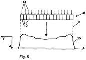
- FIG Fig. 5 is shown as an example, a targeted distribution of the irradiated laser energy over the irradiated area are brought about.
- the irradiated laser energy in the width direction Y of the edge band 4 is varied.
- individual radiation elements 10 of an exemplary radiation module 8 are controlled with separate control signals 14.
- the different control signals 14 can be used to selectively generate the exemplary distribution 15 of the irradiated laser energy over the extent of the irradiated area in the direction Y of the layer or edge band 4.
Landscapes
- Engineering & Computer Science (AREA)
- Physics & Mathematics (AREA)
- Mechanical Engineering (AREA)
- Optics & Photonics (AREA)
- Plasma & Fusion (AREA)
- Electromagnetism (AREA)
- Health & Medical Sciences (AREA)
- Thermal Sciences (AREA)
- Toxicology (AREA)
- Manufacturing & Machinery (AREA)
- Life Sciences & Earth Sciences (AREA)
- Microelectronics & Electronic Packaging (AREA)
- Wood Science & Technology (AREA)
- Forests & Forestry (AREA)
- Laser Beam Processing (AREA)
- Semiconductor Lasers (AREA)
Description
- Die Erfindung betrifft eine Vorrichtung gemäß dem Oberbegriff des Anspruchs 1 und ein Verfahren gemäß Anspruch 10 zum Aufbringen eines Kantenbandes auf die Schmalseite eines Werkstücks. Eine Vorrichtung gemäß dem Oberbegriff des Anspruchs 1 ist aus der
EP 2 345 518 A1 bekannt. Bei den Kantenbändern der in Rede stehenden Art handelt es sich um Kaschierungsmaterialien, welche auf die Schmalseiten von vorzugsweise plattenförmigen Werkstücken aufgebracht werden, um deren Oberflächen ein gewünschtes optisches Erscheinungsbild zu verleihen und/oder diese vor mechanischen oder sonstigen Einflüssen zu schützen. Bei den vorzugsweise plattenförmigen Werkstücken kann es sich beispielsweise um Werkstücke aus Holz oder Holzersatzwerkstoffen wie HDF, MDF, Spanplatten, Laminaten oder dergl. handeln, vorzugsweise handelt es sich bei den Werkstücken um Möbelplatten, also plattenförmige Halbzeuge für die Möbelherstellung.
Das Aufbringen der Kantenbänder auf die Schmalseiten dieser Werkstücke wird regelmäßig dadurch bewerkstelligt, dass eine Schicht, insbesondere eine Schicht des Kantenbandes, aktiviert wird, um eine Verbindung des Kantenbandes mit der Schmalseite zu ermöglichen. Es handelt sich bei dieser Haftschicht oder haftvermittelnden Schicht insbesondere um eine wärmeaktivierbare Schicht, beispielsweise um eine Kunststoffschicht, die durch den Strahlungseintrag an- oder aufgeschmolzen wird, um so eine Haftschicht oder haftvermittelnde Schicht zu bilden.
Für die Aktivierung derartiger Schichten haben sich in der Vergangenheit Laser bewährt, insbesondere aufgrund ihrer Eigenschaft, um einen hinsichtlich Wirkungsort und Leistung präzise steuerbaren Energieeintrag in die Schicht zu ermöglichen. Nachteilig ist jedoch, dass bei konventionellen Lasersystemen, wie sie beispielsweise in derDE 10 2009 050 859 A1 beschrieben sind, Strahlführungsmaßnahmen, wie beispielsweise die beschriebene Prismenoptik, notwendig sind, um den Laserstrahl auf das Kantenband zu richten. Dies liegt daran, dass es in der Praxis häufig notwendig ist, die Schicht erst unmittelbar vor dem Inkontaktbringen des Kantenbands mit der Schmalseite zu aktivieren, d.h. die Strahlung in einem Zuführbereich, in dem das Kantenband bereits nahe der Schmalseite und in einem zur Schmalseite recht flachen Winkel verläuft, in die Schicht einzubringen. Mit den konventionellen im Stand der Technik beschriebenen Laseraggregaten, die bei derartigen Verfahren und Vorrichtungen zur Anwendung kommen, wurde bisher der Laserstrahl ortsfern vom Zuführbereich erzeugt und durch im Zuführbereich oder im Bereich des Zuführbereichs angeordnete Optiken auf die Schicht gelenkt. Dies bringt den Nachteil mit sich, dass durch die Verluste, die durch die optischen Komponenten zwangsweise auftreten, insgesamt nur ein recht geringer Wirkungsgrad bezogen auf den tatsächlich für die Aktivierung zur Verfügung stehenden Teil der erzeugten Laserleistung im Verhältnis zur aufgewendeten Leistung zur Verfügung steht. - Der Erfindung liegt daher die Aufgabe zugrunde, eine Vorrichtung und ein Verfahren zum Aufbringen eines Kantenbandes auf eine Schmalseite eines Werkstücks zur Verfügung zu stellen, welches hinsichtlich der für die Aktivierung der Schicht notwendigen Energie einen besseren Wirkungsgrad aufweist.
- Die Aufgabe wird gelöst durch eine Vorrichtung und ein Verfahren mit den Merkmalen der unabhängigen Ansprüche. Die Merkmale der abhängigen Ansprüche betreffen vorteilhafte Ausführungsformen.
Das erfindungsgemäße Verfahren sieht vor, dass die Laserstrahlung in einem Zuführbereich zwischen dem Kantenband und der Schmalseite erzeugt wird. Es hat sich gezeigt, dass es möglich ist, eine Strahlungsquelle derart zu gestalten, dass diese in dem räumlich beengten Zuführbereich angeordnet werden kann und dabei noch genug Leistung erzeugt, um ein Aufbringen einer Kante auf ein Werkstück und ein Aktivieren einer Haftschicht oder haftvermittelnden Schicht zu ermöglichen. Dabei muss lediglich ein kurzer Weg von der Strahlung überbrückt werden, und es sind auch idealerweise keine Strahlumlenkungseinrichtungen, wie Prismen, Spiegel oder ähnliches notwendig. - Bei den Strahlungselementen handelt es sich um Halbleiterelemente. Bei diesen Laserstrahlung emittierenden Einheiten handelt es sich vorzugsweise um Oberflächenemitter, wie beispielsweise sogenannte VCSEL-Einheiten (Vertical Cavity Surface Emitting Laser). Die einzelnen Laserstrahlung emittierenden Einheiten weisen dabei vorzugsweise Abmessungen von nur wenigen Mikrometern aus. Die einzelnen Einheiten können zwar nur eine sehr geringe Laserleistung abgeben, durch die Vielzahl der Einheiten, die auf einem Strahlungselement bzw. auf einem Strahlungsmodul angeordnet werden können, lässt sich jedoch überraschenderweise insgesamt eine Leistung erzeugen, die aufgrund der direkten Einstrahlung über eine sehr kurze Strecke ausreicht, um die Schicht zu aktivieren.
Insbesondere um die Parallelität der emittierten Laserleistung sicherzustellen, können optische Elemente zwischen den Laserstrahlung emittierenden Einheiten und der zu aktivierenden Schicht angeordnet sein. Dabei handelt es sich vorzugsweise um Mikrolinsen, von denen vorzugsweise ebenfalls eine Mehrzahl Mikrolinsen für jedes Strahlungselement vorgesehen ist. Die Mikrolinsen lassen sich dann vorteilhafterweise nebeneinander anordnen, um so die Laserstrahlung emittierende Fläche des Strahlungselements zu bedecken. - Die einzelnen, Laserstrahlung emittierenden Einheiten erzeugen so eine Vielzahl einzelner Laserstrahlen, die vorzugsweise als flächiges Rastermuster auf die Schicht gerichtet sind. Die Laserstrahlen treffen auf verschiedenen Punkten auf und ermöglichen es so, die eingestrahlte Laserleistung gezielt auf die Fläche der Schicht zu verteilen.
- Es ist besonders vorteilhaft, wenn einzelne Laserlicht emittierende Einheiten und/oder einzelne Strahlungselemente und/oder Gruppen von Einheiten und/oder Strahlungselementen einzeln ansteuerbar sind. Hierdurch können im Betrieb gezielt verschiedene Intensitätsverteilungen erzeugt werden.
- Es ist zum Beispiel ermöglicht, eine besonders intensive Aktivierung der Schicht im Randbereich durchzuführen, beispielsweise eine Kunststoffschicht im Bereich der Ränder des Kantenbandes gezielt stärker aufzuschmelzen, um hier beispielsweise sicherzugehen, dass eine wasserdampfdichte Verbindung zu einer Oberflächenversiegelung der Flächenseiten des Werkstücks geschaffen wird.
- Es kann jedoch auch möglich und wünschenswert sein, die Intensitätsverteilung in der Förderrichtung der bestrahlten Schicht gezielt zu steuern. Hierdurch wird aufgrund der Relativbewegung zwischen Schicht und Strahlungsquelle letztendlich ein zeitlicher Verlauf der auf eine einzelne Einheit der bestrahlten Fläche abgegebenen Laserleistung gezielt erzeugt. So kann beispielsweise im Fall aufzuschmelzender Kunststoffkanten der Aufheizvorgang optimal gesteuert werden, um beispielsweise gezielt ein gewisses Temperaturprofil in der Dickenrichtung der Schicht zu erzeugen oder eine bestimmte aufgeschmolzene Schichtdicke zu erreichen, ohne dass kritische Temperaturen an der direkt bestrahlten Oberfläche überschritten werden.
- Vorzugsweise weist die Vorrichtung eine Schutzelelement, insbesondere eine Schutzscheibe auf. Die Ausgestaltung des Schutzelements als Schutzscheibe ist nur eine mögliche vorteilhafte Ausführungsform. Zur sprachlichen Vereinfachung wird im Folgenden jedoch der Begriff Schutzscheibe auch stellvertretend für andere Schutzelemente verwendet. Diese Schutzscheibe ist dafür eingerichtet, das Strahlungsmodul vor Beschädigungen und/oder Verschmutzungen zu schützen. Dabei schützt die Schutzscheibe insbesondere die Strahlungselemente und/oder optische Elemente, wie beispielsweise Linsen bzw. Mikrolinsen. Besonders vorteilhaft kann das Schutzelement bzw. die Schutzscheibe als halbdurchlässiger Spiegel ausgestaltet sein. Dieser ist bevorzugt so angeordnet, dass vom Kantenband ausgehende Strahlung durch den Spiegel reflektiert wird. Hierdurch wird es ermöglicht, zum Einen Elemente des Strahlungsmoduls, insbesondere die Strahlungselemente und/oder optische Elemente vor Beschädigungen durch reflektierte Strahlung zu schützen. Weiterhin wird eine Energieersparnis erzielt, indem vom Kantenband reflektierte Strahlung wieder zurück auf das Kantenband reflektiert wird.
- Bei der Aktivierung der Haftschicht oder haftvermittelnden Schicht entstehen regelmäßig Emissionen, die sich - hauptsächlich in Form von Partikeln - auf Oberflächen niederschlagen können. Insbesondere wenn dies optische Elemente im Strahlengang der Laserstrahlung betrifft, wird hierdurch regelmäßig die Leistung und damit die Funktionsweise des Strahlungsmoduls beeinträchtigt. Auch sind die laseremittierenden Elemente bzw. deren Optiken empfindlich gegenüber Beschädigungen durch mechanische Beeinträchtigungen, wie sie in einem Produktionsumfeld durchaus zu erwarten sind. Der Vorteil einer Schutzscheibe liegt daher darin, dass mögliche Beschädigungen und/ oder Verschmutzungen die Schutzscheibe betreffen und nicht andere Elemente des Strahlungsmoduls. Im Gegensatz zu den meisten anderen Bauelementen eines erfindungsgemäßen Strahlungsmoduls lässt sich die Schutzscheibe in einfacher Weise und mit niedrigen Kosten austauschen und so in vorteilhafter Weise als Verschleißteil auslegen.
- Dabei ist vorzugsweise eine Erkennungseinrichtung vorgesehen, die Verschmutzungen und/oder Beschädigungen der Schutzscheibe detektiert. Eine entsprechende Sensorik kann beispielsweise in Form einer speziellen Schicht auf die Schutzscheibe aufgebracht werden. Auf diese Weise können Verschmutzungen und Beschädigungen der Schutzscheibe detektiert werden und so ein rechtzeitiger Austausch der Schutzscheibe veranlasst werden, bevor es zu einer Beeinträchtigung des Produktionsablaufs aufgrund von Verschmutzungen oder Beschädigungen der Schutzscheibe kommt.
- Vorteilhafterweise ist eine Absaugeinrichtung zur Absaugung von Luft vorgesehen. Das Absaugen der Luft, insbesondere aus dem Bereich zwischen dem Strahlungsmodul und dem Kantenband hat den Vorteil, dass mit der Absaugung auch Emissionen, insbesondere bei der Laserbeaufschlagung des Kantenbands freigesetzte Gase, abgesaugt werden. Verschmutzungen von Elementen des Strahlungsmoduls durch diese Gase, insbesondere optische Elemente und/oder eine Schutzscheibe, werden durch das Absaugen der Luft verhindert oder zumindest vermindert.
- Es ist vorteilhaft, wenn die Vorrichtung eine Verstelleinrichtung für die Verstellung der Position des Strahlungsmoduls relativ zum Kantenband aufweist. Durch das Verstellen der Position des Strahlungsmoduls relativ zum Kantenband kann in vorteilhafter Weise auf unterschiedliche Produktionsbedingungen reagiert werden. Insbesondere kann so die Vorrichtung auf die Verarbeitung von Kantenbändern unterschiedlicher Breite eingestellt werden. Besonders vorteilhaft ist es, wenn die Verstellung der Position des Strahlungsmoduls in der Breitenrichtung des Kantenbands möglich ist. Bei breiteren oder schmaleren Kantenbändern kann das Strahlungsmodul so in vorteilhafter Weise im Hinblick auf die Breite des Kantenbands positioniert werden.
- Besonders vorteilhaft ist eine Verstelleinrichtung, die ein Anfahren einer Wartungsposition für die Wartung eines Strahlungsmoduls ermöglicht. Unter einer Wartungsposition ist dabei eine Position zu verstehen, in der zu wartende Bestandteile des Strahlungsmoduls leicht zugänglich sind oder zumindest leichter zugänglich sind als in der Position, welche das Strahlungsmodul während der Produktion einnimmt. Insbesondere der Austausch einer Schutzscheibe kann so erleichtert werden.
- Vorzugsweise weist die erfindungsgemäße Vorrichtung weiterhin Absorberelemente zur Absorption von Strahlung auf. Bei einer erfindungsgemäßen Vorrichtung kann es sein, dass Laserstrahlung, insbesondere am Kantenband vorbei, emittiert wird. Dies kann beispielsweise dann der Fall sein, wenn die Laserstrahlung bereits erzeugt wird, bevor das Kantenband den Wirkbereich der Laserstrahlung erreicht hat bzw. wenn Laserstrahlung noch erzeugt wird, nachdem das Ende eines Kantenbands den Wirkbereich der Laserstrahlung verlassen hat. Ebenfalls ist es möglich, dass Laserstrahlung den Kantenbereich der Ränder des Kantenbandes passiert. Um eine gute Anbindung der Kante zu erreichen, muss die Haftschicht oder die haftvermittelnde Schicht bis zum Rand des Kantenbands aktiviert werden. Es wird sich daher in der Praxis kaum vermeiden lassen, dass ein gewisser Anteil der Laserstrahlung in den Randbereichen des Kantenbands an diesem vorbei abgestrahlt wird.
- Um zu verhindern, dass diese emittierende Laserstrahlung andere Bestandteile der Vorrichtung beschädigt, ist es vorteilhaft, Absorberelemente zum Auffangen dieser Laserstrahlung vorzusehen. Die Oberflächen, welche die Laserstrahlung absorbieren, sind dabei vorzugsweise wassergekühlt, d.h. sie sind aus einem Material mit hoher Wärmeleitfähigkeit, beispielsweise einem Metall, und stehen in direktem thermischen Kontakt mit wasserführenden Elementen, wie beispielsweise Kühlleitungen, so dass durch die Absorption des Laserlichts entstehende Wärme zunächst durch die Absorberelemente abgeleitet und dann eine Kühlflüssigkeit, bei der es sich insbesondere um Wasser handeln kann, abgegeben wird. Grundsätzlich sind noch weitere vorteilhafte Ausgestaltungen der Absorberelemente denkbar. So können die Absorberelemente luftgekühlt sein. Vorteilhaft in diesem Zusammenhang ist eine Luftkühlungseinrichtung, wie beispielsweise ein Ventilator und/oder eine die Luftkühlung begünstigende geometrische Ausgestaltung der Absorberelemente, beispielsweise durch angeformte Kühlfinger oder -rippen. Auch können die Absorber als aktive Kühlelemente - sogenannte Peltierelemente ausgebildet sein.
- Das erfindungsgemäße Verfahren sieht vorzugsweise vor, dass die Temperatur des Kantenbandes gemessen wird. Dabei wird vorzugsweise die Temperatur der Haftschicht oder der haftvermittelnden Schicht gemessen. Durch diese Temperatur kann, insbesondere wenn die Messung nach der Aktivierung erfolgt, ein Rückschluss auf das Maß der Aktivierung gezogen werden. Vorzugsweise wird die Messung dabei zwischen einer Fügeposition, in der das Kantenband an die Schmalseite gedrückt wird, und dem Rastermuster der Laserstrahlung gemessen. Eine entsprechende Temperaturmesseinrichtung ist dementsprechend vorzugsweise am Strahlungsmodul, insbesondere in einem Bereich zwischen den Laserstrahlung emittierenden Strahlungselementen und der Fügeposition angeordnet.
- Durch eine derartige, vorzugsweise berührungslose, Temperaturmessung ist es möglich, die Vorrichtung in Abhängigkeit von der gemessenen Temperatur zu steuern. Vorzugsweise betrifft dies die abgegebene Laserleistung. Besonders vorteilhaft ist es, wenn eine Regelung der Vorrichtung, insbesondere der Leistung der Laserstrahlen, vorgesehen ist. Eine Regelung ist insbesondere eine Steuerung, die einen Soll-Ist-Wert-Vergleich, insbesondere im Hinblick auf die Temperatur, durchführt und in Abhängigkeit des Ergebnisses dieses Soll-Ist-Wert-Vergleichs die Vorrichtung, insbesondere die Leistung der Laserstrahlen, ansteuert. Hierdurch kann eine gleichbleibende Qualität der Aktivierung der Haftschicht bzw. der haftvermittelnden Schicht sichergestellt werden, auch wenn die Laserstrahlungsleistung Schwankungen, beispielsweise aufgrund von Verschmutzungen optischer Elemente unterworfen ist. Eine solche vorteilhafte Temperaturmessung kann auch zum Detektieren von Fehlern des Kantenbandes genutzt werden. Weist ein zu verarbeitendes Kantenband herstellungsseitig Fehler, insbesondere Materialfehler auf, so können sich diese in einer Änderung des thermischen Verhaltens bei der Beaufschlagung des Kantenbandes mit Laserlicht bemerkbar machen, die vorzugsweise durch die Temperaturmessung erfasst wird.
- Die Erfindung wird im Folgenden anhand der
Fig. 1 bis 5 schematisch näher erläutert. -
Fig. 1 zeigt eine schematische Darstellung einer beispielhaften erfindungsgemäßen Vorrichtung. -
Fig. 1a zeigt einen Ausschnitt ausFig. 1 , wobei die beispielhafte erfindungsgemäße Vorrichtung eine zusätzliche Temperaturmesseinrichtung aufweist. -
Fig. 1b zeigt einen Ausschnitt ausFig. 1 , wobei die beispielhafte erfindungsgemäße Vorrichtung eine zusätzliche Schutzscheibe aufweist. -
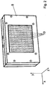
Fig. 2 zeigt eine schematische perspektivische Darstellung eines beispielhaften erfindungsgemäßen Strahlungsmoduls. -
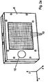
Fig. 2a zeigt eine schematische perspektivische Darstellung eines weiteren beispielhaften erfindungsgemäßen Strahlungsmoduls mit einer Temperaturmesseinrichtung. -
Fig. 3 zeigt eine Schnittdarstellung eines beispielhaften erfindungsgemäßen Strahlungsmoduls. -
Fig. 3a zeigt das Strahlungsmodul ausFig. 3 mit einer zusätzlichen Schutzscheibe. -
Fig. 3b zeigt das Strahlungsmodul ausFig. 3 mit einer zusätzlichen Absaugeinrichtung. -
Fig. 3c zeigt das Strahlungsmodul ausFig. 3 mit zusätzlichen Absorberelementen. -
Fig. 4 zeigt schematisch eine perspektivische Darstellung eines beispielhaften Strahlungselements. -
Fig. 5 zeigt eine schematische Darstellung einer gezielten Erzeugung einer Intensitätsverteilung mit einer beispielhaften erfindungsgemäßen Strahlungsquelle. - Um vorzugsweise eine möglichst parallele Laserstrahlung 9 zu erhalten, können wie im in
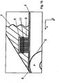
Fig. 3 gezeigten Beispiel Mikrolinsen 11 oder auch konventionelle Optiken 12, wie beispielsweise Zylinderlinsen, im Strahlengang angeordnet sein. Dabei ist es beispielsweise möglich - wie dies inFig. 4 schematisch dargestellt ist - einzelne Laserlicht emittierende Einheiten 13, die über die lichtemittierende Oberfläche des Strahlungselements 10 verteilt sind, jeweils mit einer Mikrolinse 11 zu versehen, um eine gezielte Fokussierung und/oder Auffächerung der von der jeweiligen Einheit 13 abgegebenen Laserstrahlung 9 zu erzeugen - Werden einzelne Strahlungselemente 10 eines Strahlungsmoduls 8 oder einzelne Einheiten 13 eines Strahlungselements 10 einzeln gezielt angesteuert - was natürlich auch gruppenweise geschehen kann - so kann, wie es in
Fig. 5 beispielhaft gezeigt ist, eine gezielte Verteilung der eingestrahlten Laserenergie über die bestrahlte Fläche herbeigeführt werden. In dem inFig. 5 gezeigten Beispiel wird die eingestrahlte Laserenergie in der Breitenrichtung Y des Kantenbandes 4 variiert. Hierfür werden beispielhaft einzelne Strahlungselemente 10 eines beispielhaften Strahlungsmoduls 8 mit separaten Steuersignalen 14 angesteuert. Durch die unterschiedlichen Steuersignale 14 kann gezielt die beispielhafte Verteilung 15 der eingestrahlten Laserenergie über die Erstreckung des bestrahlten Bereichs in Richtung Y der Schicht bzw. des Kantenbandes 4 erzeugt werden.
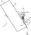
Im Zuführbereich 7 zwischen Kantenbereich 2 und Schmalseite 3 ist das beispielhafte Strahlungsmodul 8 angeordnet. Das Strahlungsmodul 8 gibt Laserstrahlung 9 in Strahlungsrichtung Z ab. Diese trifft auf das Kantenband 4, wo sie eine in
Das beispielhafte Strahlungsmodul 8 weist eine Vielzahl Strahlungselemente 10 auf. Die Strahlungselemente 10 sind mit ihrer Laserstrahlung 9 emittierenden Fläche ebenfalls zumindest im Wesentlichen parallel zu Zuführrichtung X und Breitenrichtung Y ausgerichtet.
Das beispielhafte Strahlungsmodul 8 kann vorteilhafterweise eine Temperaturmesseinrichtung 16 aufweisen. Diese ist in dem in
Die in
Die in
Claims (13)
- Vorrichtung (1) zum Aufbringen eines Kantenbandes (4) auf eine Schmalseite (3) eines Werkstücks, insbesondere aus Holz oder einem Holzersatzwerkstoff, mit einer Strahlenquelle zur Aktivierung einer Haftschicht oder haftvermittelnden Schicht, wobei die Strahlungsquelle ein Strahlungsmodul (8) mit einer Mehrzahl Laserstrahlung (9) emittierender Strahlungselemente (10) ist,
dadurch gekennzeichnet,
dass das Strahlungsmodul (8) flächig gestaltet ist, wobei die Strahlung wenigstens in etwa quer zu den Haupterstreckungsrichtungen des Strahlungsmoduls (8) abgegeben wird, und dass die Strahlungsquelle in einem Zuführbereich zwischen dem Kantenband und der Kante angeordnet ist, wobei die Strahlungselemente (10) Halbleiterelemente sind, die jeweils eine Mehrzahl Laserstrahlung emittierender Einheiten (13), insbesondere Oberflächenemitter, wie vorzugsweise VCSEL, aufweisen. - Vorrichtung nach Anspruch 1,
dadurch gekennzeichnet,
dass die Strahlungselemente (10) derart flächig angeordnet und/oder derart gestaltet sind, dass sie die Laserstrahlung in einer von den Flächenerstreckungsrichtungen (X, Y) ihrer Laserstrahlung emittierenden Oberfläche verschiedenen, vorzugsweise wenigstens ungefähr senkrechten Richtung (Z) emittieren. - Vorrichtung (1) nach einem der Ansprüche 1 bis 2,
dadurch gekennzeichnet,
dass die Strahlungsquelle so angeordnet ist, dass die Strahlung auf die zu aktivierende Schicht in einem Winkel von wenigstens 75° und höchstens 105°, bevorzugt wenigstens teilweise senkrecht, auftrifft. - Vorrichtung (1) nach einem der Ansprüche 1 bis 3,
dadurch gekennzeichnet,
dass einzelne Strahlungselemente (10) und/oder Einheiten (13) und/oder Gruppen von Strahlungselementen (10) und/oder Einheiten (13) einzeln ansteuerbar sind. - Vorrichtung (1) nach einem der vorigen Ansprüche,
dadurch gekennzeichnet,
dass die Vorrichtung (1), insbesondere das Strahlungsmodul (8), ein Schutzelement, vorzugsweise eine Schutzscheibe (17) aufweist, die dazu ausgebildet ist, das Strahlungsmodul (8), insbesondere die Strahlungselemente (10) und/oder ein optisches Element (11, 12) des Strahlungsmoduls (8) vor Beschädigungen und/oder Verschmutzungen, insbesondere aufgrund von Emissionen, die bei der Aktivierung der Haftschicht oder haftvermittelnden Schicht entstehen, zu schützen. - Vorrichtung (1) nach Anspruch 5,
dadurch gekennzeichnet,
dass die Vorrichtung (1), insbesondere das Strahlungsmodul (8), eine Erkennungseinrichtung zur Erkennung von Verschmutzungen und/oder Beschädigungen der Schutzscheibe (17) aufweist. - Vorrichtung (1) nach einem der vorigen Ansprüche,
dadurch gekennzeichnet,
dass die Vorrichtung (1) eine Absaugeinrichtung (18) zur Absaugung von Luft aus dem Bereich zwischen dem Strahlungsmodul (8), insbesondere den Strahlungselementen (10), und dem Kantenband (4) aufweist. - Vorrichtung (1) nach einem der vorigen Ansprüche,
dadurch gekennzeichnet,
dass die Vorrichtung (1) eine Verstelleinrichtung für die Verstellung der Position des Strahlungsmoduls (8) relativ zum Kantenband (4), insbesondere in der Breitenrichtung (Y) des Kantenbands (4) aufweist, insbesondere wobei die Verstelleinrichtung ein Anfahren einer Wartungsposition für die Wartung des Strahlungsmoduls (8) ermöglicht. - Vorrichtung (1) nach einem der vorigen Ansprüche,
dadurch gekennzeichnet,
dass die Vorrichtung (1) ein, vorzugsweise flüssigkeitsgekühltes Absorberelement (19, 20) aufweist, das vorzugsweise auf der von dem Strahlungsmodul (8) abgewandten Seite des Kantenbandes (4) angeordnet ist. - Verfahren zum Aufbringen eines Kantenbandes auf eine Schmalseite eines Werkstücks, insbesondere aus Holz oder einem Holzersatzwerkstoff, mittels einer Vorrichtung nach einem der vorigen Ansprüche, wobei die Haftschicht oder haftvermittelnde Schicht durch Laserstrahlung (9) aktiviert wird, wobei eine Mehrzahl einzelner Laserstrahlen (9) erzeugt und, vorzugsweise als flächiges Rastermuster, auf verschiedene Punkte der Schicht gerichtet wird,
dadurch gekennzeichnet,
dass die Laserstrahlung in einem Zuführbereich (7) zwischen dem Kantenband (4) und der Schmalseite (3) erzeugt wird. - Verfahren nach Anspruch 10,
dadurch gekennzeichnet,
dass, vorzugsweise zur gezielten Erzeugung einer vorgebbaren Flächenverteilung (15) der eingestrahlten Laserleistung auf der Schicht, die Leistung einzelner Laserstrahlen (9) und/oder einzelner Gruppen von Laserstrahlen (9) gesteuert wird. - Verfahren nach einem der Ansprüche 10 oder 11,
dadurch gekennzeichnet,
dass die Temperatur des Kantenbandes, insbesondere der Haftschicht oder der haftvermittelnden Schicht, insbesondere in einem Bereich des Kantenbandes zwischen dem Rastermuster und einer Fügeposition, in der das Kantenband an die Schmalseite gedrückt wird, gemessen wird. - Verfahren nach Anspruch 12,
dadurch gekennzeichnet,
dass die Vorrichtung (1), insbesondere die Leistung der Laserstrahlen (9), in Abhängigkeit von der gemessenen Temperatur gesteuert, insbesondere geregelt, wird.
Priority Applications (1)
| Application Number | Priority Date | Filing Date | Title |
|---|---|---|---|
| PL15001075T PL2952307T3 (pl) | 2014-06-05 | 2015-04-15 | Urządzenie i sposób do nanoszenia taśmy krawędziowej na wąski bok przedmiotu obrabianego |
Applications Claiming Priority (1)
| Application Number | Priority Date | Filing Date | Title |
|---|---|---|---|
| DE102014008455.8A DE102014008455A1 (de) | 2014-06-05 | 2014-06-05 | Vorrichtung und Verfahren zum Aufbringen eines Kantenbandes auf eine Schmalseite eines Werkstücks |
Publications (2)
| Publication Number | Publication Date |
|---|---|
| EP2952307A1 EP2952307A1 (de) | 2015-12-09 |
| EP2952307B1 true EP2952307B1 (de) | 2018-04-25 |
Family
ID=53016430
Family Applications (1)
| Application Number | Title | Priority Date | Filing Date |
|---|---|---|---|
| EP15001075.9A Active EP2952307B1 (de) | 2014-06-05 | 2015-04-15 | Vorrichtung und verfahren zum aufbringen eines kantenbandes auf eine schmalseite eines werkstücks |
Country Status (4)
| Country | Link |
|---|---|
| EP (1) | EP2952307B1 (de) |
| DE (1) | DE102014008455A1 (de) |
| ES (1) | ES2677999T3 (de) |
| PL (1) | PL2952307T3 (de) |
Cited By (1)
| Publication number | Priority date | Publication date | Assignee | Title |
|---|---|---|---|---|
| EP3838525A1 (de) * | 2019-12-18 | 2021-06-23 | SCM Group S.p.A. | Kantenanleimmaschine für platte |
Families Citing this family (12)
| Publication number | Priority date | Publication date | Assignee | Title |
|---|---|---|---|---|
| DE102014017088A1 (de) | 2014-11-20 | 2016-05-25 | Kautex Textron Gmbh & Co. Kg | Vorrichtung und Verfahren zum Erzeugen einer Verstärkungsstruktur auf einer Formkörperoberfläche |
| DE102015000043A1 (de) * | 2015-01-09 | 2016-07-14 | Ima Klessmann Gmbh Holzbearbeitungssysteme | Verfahren zur Bearbeitung von Werkstücken, insbesondere Kantenbändern, und Vorrichtung zur Durchführung des Verfahrens |
| ITUB20150532A1 (it) | 2015-04-21 | 2016-10-21 | Scm Group Spa | Apparato di bordatura |
| DE102015012820B4 (de) | 2015-05-28 | 2017-09-14 | Michael Karau | Mindestens temporär wirkende, sprühfähige, nicht korrosive Oberflächenfunktionsbeschichtung und deren Verwendung |
| EP3187320B1 (de) | 2015-12-29 | 2020-04-15 | Michael Karau | Verfahren zum befestigen von streifenförmigen flächengebilden, insbesondere kantenbändern an schmalseiten von werkstücken |
| DE102017205208A1 (de) * | 2017-03-28 | 2018-10-04 | Homag Gmbh | Vorrichtung und Verfahren zum Beschichten eines Werkstücks |
| IT201700052332A1 (it) * | 2017-05-15 | 2018-11-15 | Scm Group Spa | Dispositivo per ravvivare il bordo di un pannello, macchina bordatrice che lo comprende e metodo per ravvivare un bordo applicato ad un pannello |
| DE102019120376A1 (de) * | 2019-07-29 | 2021-02-04 | Ima Schelling Deutschland Gmbh | Kantenverarbeitungsverfahren |
| DE102019133934A1 (de) * | 2019-12-11 | 2021-06-17 | Homag Gmbh | Vorrichtung und Verfahren zum Beschichten eines Werkstücks |
| DE102022115053A1 (de) | 2022-06-15 | 2023-12-21 | Volkswagen Aktiengesellschaft | Galvanische Monozelle sowie Verfahren und Vorrichtung zur Herstellung einer solchen |
| DE102022119457A1 (de) | 2022-08-03 | 2024-02-08 | Homag Gmbh | Vorrichtung zum Beschichten eines Werkstücks |
| FR3146291B1 (fr) * | 2023-03-02 | 2025-05-02 | Coriolis Group | Machine de placement de fibres avec des moyens de chauffe laser particuliers |
Citations (1)
| Publication number | Priority date | Publication date | Assignee | Title |
|---|---|---|---|---|
| WO2015067692A1 (de) * | 2013-11-07 | 2015-05-14 | Homag Holzbearbeitungssysteme Gmbh | Verfahren zum aufbringen einer beschichtung auf werkstücke und vorrichtung zum beschichten von werkstücken |
Family Cites Families (8)
| Publication number | Priority date | Publication date | Assignee | Title |
|---|---|---|---|---|
| US6451152B1 (en) * | 2000-05-24 | 2002-09-17 | The Boeing Company | Method for heating and controlling temperature of composite material during automated placement |
| US6384372B1 (en) * | 2000-07-20 | 2002-05-07 | Advanced Micro Devices, Inc. | Method and system for dust and fume removal in laser marking machines |
| DE102009050859A1 (de) | 2009-10-27 | 2011-04-28 | Ima Klessmann Gmbh Holzbearbeitungssysteme | Vorrichtung und Verfahren zur Bekantung von Werkstücken |
| DE102009050858A1 (de) * | 2009-10-27 | 2011-04-28 | Ima Klessmann Gmbh Holzbearbeitungssysteme | Vorrichtung und Verfahren zur Bekantung von Werkstücken |
| ES2480270T3 (es) * | 2010-01-18 | 2014-07-25 | Homag Holzbearbeitungssysteme Ag | Dispositivo y procedimiento para el revestimiento de piezas de trabajo |
| ES2398817T3 (es) * | 2010-08-24 | 2013-03-21 | Homag Holzbearbeitungssysteme Ag | Dispositivo para el revestimiento de piezas de trabajo |
| ITUD20120020A1 (it) * | 2012-02-08 | 2013-08-09 | Seit Elettronica Srl | Apparato di aspirazione per una macchina di lavoro, quale un ponte laser per una macchina ricamatrice/cucitrice |
| DE102012102785B3 (de) * | 2012-03-30 | 2013-02-21 | Marius Jurca | Verfahren und Überwachungseinrichtung zur Erfassung und Überwachung der Verschmutzung einer optischen Komponente in einer Vorrichtung zur Lasermaterialbearbeitung |
-
2014
- 2014-06-05 DE DE102014008455.8A patent/DE102014008455A1/de not_active Withdrawn
-
2015
- 2015-04-15 PL PL15001075T patent/PL2952307T3/pl unknown
- 2015-04-15 ES ES15001075.9T patent/ES2677999T3/es active Active
- 2015-04-15 EP EP15001075.9A patent/EP2952307B1/de active Active
Patent Citations (1)
| Publication number | Priority date | Publication date | Assignee | Title |
|---|---|---|---|---|
| WO2015067692A1 (de) * | 2013-11-07 | 2015-05-14 | Homag Holzbearbeitungssysteme Gmbh | Verfahren zum aufbringen einer beschichtung auf werkstücke und vorrichtung zum beschichten von werkstücken |
Non-Patent Citations (2)
| Title |
|---|
| U WEICHMANN ET AL: "VCSEL Day-2013: High Power VCSEL Systems", 3 June 2013 (2013-06-03), pages 14, XP055344083, Retrieved from the Internet <URL:http://lpn.epfl.ch/files/content/sites/lpn/files/conferences/VCSEL_Day_2013/Abstracts.pdf> [retrieved on 20170209] * |
| VAN LEEUWEN ROBERT ET AL: "High-power vertical-cavity surface-emitting lasers for diode pumped solid-state lasers", LASER TECHNOLOGY FOR DEFENSE AND SECURITY VIII, SPIE, 1000 20TH ST. BELLINGHAM WA 98225-6705 USA, vol. 8381, no. 1, 11 May 2012 (2012-05-11), pages 1 - 7, XP060003104, DOI: 10.1117/12.920601 * |
Cited By (1)
| Publication number | Priority date | Publication date | Assignee | Title |
|---|---|---|---|---|
| EP3838525A1 (de) * | 2019-12-18 | 2021-06-23 | SCM Group S.p.A. | Kantenanleimmaschine für platte |
Also Published As
| Publication number | Publication date |
|---|---|
| PL2952307T3 (pl) | 2018-10-31 |
| EP2952307A1 (de) | 2015-12-09 |
| ES2677999T3 (es) | 2018-08-08 |
| DE102014008455A1 (de) | 2015-12-17 |
Similar Documents
| Publication | Publication Date | Title |
|---|---|---|
| EP2952307B1 (de) | Vorrichtung und verfahren zum aufbringen eines kantenbandes auf eine schmalseite eines werkstücks | |
| DE102011054941B3 (de) | Vorrichtung und Verfahren zur Korrektur der thermischen Verschiebung der Fokuslage von über Optiken geführten Laserstrahlen | |
| EP2422947B1 (de) | Vorrichtung zum Beschichten von Werkstücken | |
| EP2667998B1 (de) | Laserbearbeitungsmaschine sowie verfahren zum zentrieren eines fokussierten laserstrahles | |
| EP3119569B1 (de) | Vorrichtung zum fixieren eines kantenmaterials | |
| WO2018069308A1 (de) | Verfahren und vorrichtung zur bestimmung und zur regelung einer fokusposition eines bearbeitungsstrahls | |
| DE112006000858T5 (de) | Laserschweisssystem | |
| WO2011000013A1 (de) | Verfahren und vorrichtung zum biegen eines werkstücks | |
| DE102008027130A1 (de) | Verfahren zur trennenden Bearbeitung von Werkstücken mit einem Laserstrahl | |
| WO2023016680A1 (de) | Fügewerkzeugeinheit und werkzeugzange | |
| DE102018000441A1 (de) | Laserbearbeitungsverfahren | |
| DE102015207834A1 (de) | Bearbeitungsmaschine für ein mit einem Laserstrahl durchzuführendes Produktionsverfahren und Verfahren zu deren Betrieb | |
| DE112006000949T5 (de) | Laserschweisssystem | |
| EP3042743B1 (de) | Verfahren zur bearbeitung von werkstücken, insbesondere kantenbändern, und vorrichtung zur durchführung des verfahrens | |
| EP3189951A1 (de) | Verfahren zum herstellen einer holzwerkstoffplatte und holzwerkstoffplatten-herstellvorrichtung | |
| DE60210069T2 (de) | Verfahren und vorrichtung zum auftragen von klebstoff auf eine zellförmige oberfläche | |
| DE102018125609B4 (de) | Verfahren und Vorrichtung zum Befestigen einer Kantenleiste | |
| DE102010032781B4 (de) | Verfahren zur trennenden Bearbeitung von Werkstücken mit Laserstrahlen | |
| DE202023106863U1 (de) | Vorrichtung und System zum Laserkunststoffschweißen | |
| DE102013001486A1 (de) | Laserschweißvorrichtung | |
| DE202008010495U1 (de) | Optisches Element und Vorrichtung zum Überwachen des optischen Elements | |
| DE102011107982A1 (de) | Werkzeugkopf (LCP-Kopf) | |
| EP3656827A2 (de) | Verfahren zum fügen zweier fügeteile unter verwendung eines flächenstrahlers sowie fügevorrichtung | |
| AT523200B1 (de) | Vorrichtung zur additiven fertigung | |
| DE102021102373A1 (de) | Verfahren zum Laserhärten eines Garniturdrahtes |
Legal Events
| Date | Code | Title | Description |
|---|---|---|---|
| PUAI | Public reference made under article 153(3) epc to a published international application that has entered the european phase |
Free format text: ORIGINAL CODE: 0009012 |
|
| AK | Designated contracting states |
Kind code of ref document: A1 Designated state(s): AL AT BE BG CH CY CZ DE DK EE ES FI FR GB GR HR HU IE IS IT LI LT LU LV MC MK MT NL NO PL PT RO RS SE SI SK SM TR |
|
| AX | Request for extension of the european patent |
Extension state: BA ME |
|
| 17P | Request for examination filed |
Effective date: 20160531 |
|
| RBV | Designated contracting states (corrected) |
Designated state(s): AL AT BE BG CH CY CZ DE DK EE ES FI FR GB GR HR HU IE IS IT LI LT LU LV MC MK MT NL NO PL PT RO RS SE SI SK SM TR |
|
| STAA | Information on the status of an ep patent application or granted ep patent |
Free format text: STATUS: EXAMINATION IS IN PROGRESS |
|
| 17Q | First examination report despatched |
Effective date: 20170217 |
|
| GRAP | Despatch of communication of intention to grant a patent |
Free format text: ORIGINAL CODE: EPIDOSNIGR1 |
|
| STAA | Information on the status of an ep patent application or granted ep patent |
Free format text: STATUS: GRANT OF PATENT IS INTENDED |
|
| RIC1 | Information provided on ipc code assigned before grant |
Ipc: B23K 26/323 20140101ALI20180116BHEP Ipc: B23K 26/324 20140101ALI20180116BHEP Ipc: B29C 63/00 20060101ALI20180116BHEP Ipc: B29C 65/16 20060101ALI20180116BHEP Ipc: B23K 26/06 20140101ALI20180116BHEP Ipc: B23K 26/08 20140101ALI20180116BHEP Ipc: B27D 5/00 20060101AFI20180116BHEP Ipc: B29C 65/00 20060101ALI20180116BHEP Ipc: B23K 26/244 20140101ALI20180116BHEP |
|
| INTG | Intention to grant announced |
Effective date: 20180201 |
|
| GRAA | (expected) grant |
Free format text: ORIGINAL CODE: 0009210 |
|
| GRAS | Grant fee paid |
Free format text: ORIGINAL CODE: EPIDOSNIGR3 |
|
| STAA | Information on the status of an ep patent application or granted ep patent |
Free format text: STATUS: THE PATENT HAS BEEN GRANTED |
|
| AK | Designated contracting states |
Kind code of ref document: B1 Designated state(s): AL AT BE BG CH CY CZ DE DK EE ES FI FR GB GR HR HU IE IS IT LI LT LU LV MC MK MT NL NO PL PT RO RS SE SI SK SM TR |
|
| REG | Reference to a national code |
Ref country code: GB Ref legal event code: FG4D Free format text: NOT ENGLISH |
|
| REG | Reference to a national code |
Ref country code: CH Ref legal event code: EP |
|
| REG | Reference to a national code |
Ref country code: AT Ref legal event code: REF Ref document number: 992385 Country of ref document: AT Kind code of ref document: T Effective date: 20180515 |
|
| REG | Reference to a national code |
Ref country code: IE Ref legal event code: FG4D Free format text: LANGUAGE OF EP DOCUMENT: GERMAN |
|
| REG | Reference to a national code |
Ref country code: DE Ref legal event code: R096 Ref document number: 502015003967 Country of ref document: DE |
|
| REG | Reference to a national code |
Ref country code: ES Ref legal event code: FG2A Ref document number: 2677999 Country of ref document: ES Kind code of ref document: T3 Effective date: 20180808 |
|
| REG | Reference to a national code |
Ref country code: NL Ref legal event code: MP Effective date: 20180425 |
|
| REG | Reference to a national code |
Ref country code: LT Ref legal event code: MG4D |
|
| PG25 | Lapsed in a contracting state [announced via postgrant information from national office to epo] |
Ref country code: NL Free format text: LAPSE BECAUSE OF FAILURE TO SUBMIT A TRANSLATION OF THE DESCRIPTION OR TO PAY THE FEE WITHIN THE PRESCRIBED TIME-LIMIT Effective date: 20180425 |
|
| PG25 | Lapsed in a contracting state [announced via postgrant information from national office to epo] |
Ref country code: NO Free format text: LAPSE BECAUSE OF FAILURE TO SUBMIT A TRANSLATION OF THE DESCRIPTION OR TO PAY THE FEE WITHIN THE PRESCRIBED TIME-LIMIT Effective date: 20180725 Ref country code: SE Free format text: LAPSE BECAUSE OF FAILURE TO SUBMIT A TRANSLATION OF THE DESCRIPTION OR TO PAY THE FEE WITHIN THE PRESCRIBED TIME-LIMIT Effective date: 20180425 Ref country code: FI Free format text: LAPSE BECAUSE OF FAILURE TO SUBMIT A TRANSLATION OF THE DESCRIPTION OR TO PAY THE FEE WITHIN THE PRESCRIBED TIME-LIMIT Effective date: 20180425 Ref country code: LT Free format text: LAPSE BECAUSE OF FAILURE TO SUBMIT A TRANSLATION OF THE DESCRIPTION OR TO PAY THE FEE WITHIN THE PRESCRIBED TIME-LIMIT Effective date: 20180425 Ref country code: BG Free format text: LAPSE BECAUSE OF FAILURE TO SUBMIT A TRANSLATION OF THE DESCRIPTION OR TO PAY THE FEE WITHIN THE PRESCRIBED TIME-LIMIT Effective date: 20180725 |
|
| PG25 | Lapsed in a contracting state [announced via postgrant information from national office to epo] |
Ref country code: GR Free format text: LAPSE BECAUSE OF FAILURE TO SUBMIT A TRANSLATION OF THE DESCRIPTION OR TO PAY THE FEE WITHIN THE PRESCRIBED TIME-LIMIT Effective date: 20180726 Ref country code: HR Free format text: LAPSE BECAUSE OF FAILURE TO SUBMIT A TRANSLATION OF THE DESCRIPTION OR TO PAY THE FEE WITHIN THE PRESCRIBED TIME-LIMIT Effective date: 20180425 Ref country code: RS Free format text: LAPSE BECAUSE OF FAILURE TO SUBMIT A TRANSLATION OF THE DESCRIPTION OR TO PAY THE FEE WITHIN THE PRESCRIBED TIME-LIMIT Effective date: 20180425 Ref country code: LV Free format text: LAPSE BECAUSE OF FAILURE TO SUBMIT A TRANSLATION OF THE DESCRIPTION OR TO PAY THE FEE WITHIN THE PRESCRIBED TIME-LIMIT Effective date: 20180425 |
|
| PG25 | Lapsed in a contracting state [announced via postgrant information from national office to epo] |
Ref country code: PT Free format text: LAPSE BECAUSE OF FAILURE TO SUBMIT A TRANSLATION OF THE DESCRIPTION OR TO PAY THE FEE WITHIN THE PRESCRIBED TIME-LIMIT Effective date: 20180827 |
|
| REG | Reference to a national code |
Ref country code: DE Ref legal event code: R097 Ref document number: 502015003967 Country of ref document: DE |
|
| PG25 | Lapsed in a contracting state [announced via postgrant information from national office to epo] |
Ref country code: CZ Free format text: LAPSE BECAUSE OF FAILURE TO SUBMIT A TRANSLATION OF THE DESCRIPTION OR TO PAY THE FEE WITHIN THE PRESCRIBED TIME-LIMIT Effective date: 20180425 Ref country code: RO Free format text: LAPSE BECAUSE OF FAILURE TO SUBMIT A TRANSLATION OF THE DESCRIPTION OR TO PAY THE FEE WITHIN THE PRESCRIBED TIME-LIMIT Effective date: 20180425 Ref country code: SK Free format text: LAPSE BECAUSE OF FAILURE TO SUBMIT A TRANSLATION OF THE DESCRIPTION OR TO PAY THE FEE WITHIN THE PRESCRIBED TIME-LIMIT Effective date: 20180425 Ref country code: EE Free format text: LAPSE BECAUSE OF FAILURE TO SUBMIT A TRANSLATION OF THE DESCRIPTION OR TO PAY THE FEE WITHIN THE PRESCRIBED TIME-LIMIT Effective date: 20180425 Ref country code: DK Free format text: LAPSE BECAUSE OF FAILURE TO SUBMIT A TRANSLATION OF THE DESCRIPTION OR TO PAY THE FEE WITHIN THE PRESCRIBED TIME-LIMIT Effective date: 20180425 |
|
| PG25 | Lapsed in a contracting state [announced via postgrant information from national office to epo] |
Ref country code: SM Free format text: LAPSE BECAUSE OF FAILURE TO SUBMIT A TRANSLATION OF THE DESCRIPTION OR TO PAY THE FEE WITHIN THE PRESCRIBED TIME-LIMIT Effective date: 20180425 |
|
| PLBE | No opposition filed within time limit |
Free format text: ORIGINAL CODE: 0009261 |
|
| STAA | Information on the status of an ep patent application or granted ep patent |
Free format text: STATUS: NO OPPOSITION FILED WITHIN TIME LIMIT |
|
| 26N | No opposition filed |
Effective date: 20190128 |
|
| PG25 | Lapsed in a contracting state [announced via postgrant information from national office to epo] |
Ref country code: SI Free format text: LAPSE BECAUSE OF FAILURE TO SUBMIT A TRANSLATION OF THE DESCRIPTION OR TO PAY THE FEE WITHIN THE PRESCRIBED TIME-LIMIT Effective date: 20180425 |
|
| PG25 | Lapsed in a contracting state [announced via postgrant information from national office to epo] |
Ref country code: AL Free format text: LAPSE BECAUSE OF FAILURE TO SUBMIT A TRANSLATION OF THE DESCRIPTION OR TO PAY THE FEE WITHIN THE PRESCRIBED TIME-LIMIT Effective date: 20180425 |
|
| REG | Reference to a national code |
Ref country code: CH Ref legal event code: PL |
|
| REG | Reference to a national code |
Ref country code: DE Ref legal event code: R082 Ref document number: 502015003967 Country of ref document: DE Representative=s name: THIELKING & ELBERTZHAGEN PATENTANWAELTE, DE Ref country code: DE Ref legal event code: R081 Ref document number: 502015003967 Country of ref document: DE Owner name: IMA SCHELLING DEUTSCHLAND GMBH, DE Free format text: FORMER OWNER: IMA KLESSMANN GMBH HOLZBEARBEITUNGSSYSTEME, 32312 LUEBBECKE, DE |
|
| REG | Reference to a national code |
Ref country code: BE Ref legal event code: MM Effective date: 20190430 |
|
| PG25 | Lapsed in a contracting state [announced via postgrant information from national office to epo] |
Ref country code: MC Free format text: LAPSE BECAUSE OF FAILURE TO SUBMIT A TRANSLATION OF THE DESCRIPTION OR TO PAY THE FEE WITHIN THE PRESCRIBED TIME-LIMIT Effective date: 20180425 Ref country code: LU Free format text: LAPSE BECAUSE OF NON-PAYMENT OF DUE FEES Effective date: 20190415 |
|
| PG25 | Lapsed in a contracting state [announced via postgrant information from national office to epo] |
Ref country code: LI Free format text: LAPSE BECAUSE OF NON-PAYMENT OF DUE FEES Effective date: 20190430 Ref country code: CH Free format text: LAPSE BECAUSE OF NON-PAYMENT OF DUE FEES Effective date: 20190430 |
|
| PG25 | Lapsed in a contracting state [announced via postgrant information from national office to epo] |
Ref country code: BE Free format text: LAPSE BECAUSE OF NON-PAYMENT OF DUE FEES Effective date: 20190430 |
|
| PG25 | Lapsed in a contracting state [announced via postgrant information from national office to epo] |
Ref country code: TR Free format text: LAPSE BECAUSE OF FAILURE TO SUBMIT A TRANSLATION OF THE DESCRIPTION OR TO PAY THE FEE WITHIN THE PRESCRIBED TIME-LIMIT Effective date: 20180425 |
|
| PG25 | Lapsed in a contracting state [announced via postgrant information from national office to epo] |
Ref country code: IE Free format text: LAPSE BECAUSE OF NON-PAYMENT OF DUE FEES Effective date: 20190415 |
|
| PG25 | Lapsed in a contracting state [announced via postgrant information from national office to epo] |
Ref country code: CY Free format text: LAPSE BECAUSE OF FAILURE TO SUBMIT A TRANSLATION OF THE DESCRIPTION OR TO PAY THE FEE WITHIN THE PRESCRIBED TIME-LIMIT Effective date: 20180425 |
|
| REG | Reference to a national code |
Ref country code: AT Ref legal event code: MM01 Ref document number: 992385 Country of ref document: AT Kind code of ref document: T Effective date: 20200415 |
|
| PG25 | Lapsed in a contracting state [announced via postgrant information from national office to epo] |
Ref country code: IS Free format text: LAPSE BECAUSE OF FAILURE TO SUBMIT A TRANSLATION OF THE DESCRIPTION OR TO PAY THE FEE WITHIN THE PRESCRIBED TIME-LIMIT Effective date: 20180825 |
|
| PG25 | Lapsed in a contracting state [announced via postgrant information from national office to epo] |
Ref country code: MT Free format text: LAPSE BECAUSE OF FAILURE TO SUBMIT A TRANSLATION OF THE DESCRIPTION OR TO PAY THE FEE WITHIN THE PRESCRIBED TIME-LIMIT Effective date: 20180425 Ref country code: HU Free format text: LAPSE BECAUSE OF FAILURE TO SUBMIT A TRANSLATION OF THE DESCRIPTION OR TO PAY THE FEE WITHIN THE PRESCRIBED TIME-LIMIT; INVALID AB INITIO Effective date: 20150415 |
|
| PG25 | Lapsed in a contracting state [announced via postgrant information from national office to epo] |
Ref country code: AT Free format text: LAPSE BECAUSE OF NON-PAYMENT OF DUE FEES Effective date: 20200415 |
|
| PG25 | Lapsed in a contracting state [announced via postgrant information from national office to epo] |
Ref country code: MK Free format text: LAPSE BECAUSE OF FAILURE TO SUBMIT A TRANSLATION OF THE DESCRIPTION OR TO PAY THE FEE WITHIN THE PRESCRIBED TIME-LIMIT Effective date: 20180425 |
|
| P01 | Opt-out of the competence of the unified patent court (upc) registered |
Effective date: 20230522 |
|
| PGFP | Annual fee paid to national office [announced via postgrant information from national office to epo] |
Ref country code: FR Payment date: 20230424 Year of fee payment: 9 Ref country code: ES Payment date: 20230517 Year of fee payment: 9 |
|
| PGFP | Annual fee paid to national office [announced via postgrant information from national office to epo] |
Ref country code: GB Payment date: 20230418 Year of fee payment: 9 |
|
| GBPC | Gb: european patent ceased through non-payment of renewal fee |
Effective date: 20240415 |
|
| PG25 | Lapsed in a contracting state [announced via postgrant information from national office to epo] |
Ref country code: GB Free format text: LAPSE BECAUSE OF NON-PAYMENT OF DUE FEES Effective date: 20240415 |
|
| PG25 | Lapsed in a contracting state [announced via postgrant information from national office to epo] |
Ref country code: FR Free format text: LAPSE BECAUSE OF NON-PAYMENT OF DUE FEES Effective date: 20240430 |
|
| PG25 | Lapsed in a contracting state [announced via postgrant information from national office to epo] |
Ref country code: GB Free format text: LAPSE BECAUSE OF NON-PAYMENT OF DUE FEES Effective date: 20240415 Ref country code: FR Free format text: LAPSE BECAUSE OF NON-PAYMENT OF DUE FEES Effective date: 20240430 |
|
| PGFP | Annual fee paid to national office [announced via postgrant information from national office to epo] |
Ref country code: PL Payment date: 20250328 Year of fee payment: 11 |
|
| REG | Reference to a national code |
Ref country code: ES Ref legal event code: FD2A Effective date: 20250530 |
|
| PG25 | Lapsed in a contracting state [announced via postgrant information from national office to epo] |
Ref country code: ES Free format text: LAPSE BECAUSE OF NON-PAYMENT OF DUE FEES Effective date: 20240416 |
|
| PGFP | Annual fee paid to national office [announced via postgrant information from national office to epo] |
Ref country code: IT Payment date: 20250422 Year of fee payment: 11 |
|
| PGFP | Annual fee paid to national office [announced via postgrant information from national office to epo] |
Ref country code: DE Payment date: 20251024 Year of fee payment: 11 |