EP2952280A1 - Wire-cut electrical discharge machining machine in which position of liquid level of machining fluid is adjusted at time of automatic wire threading - Google Patents
Wire-cut electrical discharge machining machine in which position of liquid level of machining fluid is adjusted at time of automatic wire threading Download PDFInfo
- Publication number
- EP2952280A1 EP2952280A1 EP15169405.6A EP15169405A EP2952280A1 EP 2952280 A1 EP2952280 A1 EP 2952280A1 EP 15169405 A EP15169405 A EP 15169405A EP 2952280 A1 EP2952280 A1 EP 2952280A1
- Authority
- EP
- European Patent Office
- Prior art keywords
- wire
- threading
- liquid level
- machined
- machining
- Prior art date
- Legal status (The legal status is an assumption and is not a legal conclusion. Google has not performed a legal analysis and makes no representation as to the accuracy of the status listed.)
- Granted
Links
Images


Classifications
-
- B—PERFORMING OPERATIONS; TRANSPORTING
- B23—MACHINE TOOLS; METAL-WORKING NOT OTHERWISE PROVIDED FOR
- B23H—WORKING OF METAL BY THE ACTION OF A HIGH CONCENTRATION OF ELECTRIC CURRENT ON A WORKPIECE USING AN ELECTRODE WHICH TAKES THE PLACE OF A TOOL; SUCH WORKING COMBINED WITH OTHER FORMS OF WORKING OF METAL
- B23H7/00—Processes or apparatus applicable to both electrical discharge machining and electrochemical machining
- B23H7/02—Wire-cutting
- B23H7/08—Wire electrodes
- B23H7/10—Supporting, winding or electrical connection of wire-electrode
- B23H7/102—Automatic wire threading
-
- B—PERFORMING OPERATIONS; TRANSPORTING
- B23—MACHINE TOOLS; METAL-WORKING NOT OTHERWISE PROVIDED FOR
- B23H—WORKING OF METAL BY THE ACTION OF A HIGH CONCENTRATION OF ELECTRIC CURRENT ON A WORKPIECE USING AN ELECTRODE WHICH TAKES THE PLACE OF A TOOL; SUCH WORKING COMBINED WITH OTHER FORMS OF WORKING OF METAL
- B23H7/00—Processes or apparatus applicable to both electrical discharge machining and electrochemical machining
- B23H7/02—Wire-cutting
-
- B—PERFORMING OPERATIONS; TRANSPORTING
- B23—MACHINE TOOLS; METAL-WORKING NOT OTHERWISE PROVIDED FOR
- B23H—WORKING OF METAL BY THE ACTION OF A HIGH CONCENTRATION OF ELECTRIC CURRENT ON A WORKPIECE USING AN ELECTRODE WHICH TAKES THE PLACE OF A TOOL; SUCH WORKING COMBINED WITH OTHER FORMS OF WORKING OF METAL
- B23H7/00—Processes or apparatus applicable to both electrical discharge machining and electrochemical machining
- B23H7/02—Wire-cutting
- B23H7/06—Control of the travel curve of the relative movement between electrode and workpiece
-
- B—PERFORMING OPERATIONS; TRANSPORTING
- B23—MACHINE TOOLS; METAL-WORKING NOT OTHERWISE PROVIDED FOR
- B23H—WORKING OF METAL BY THE ACTION OF A HIGH CONCENTRATION OF ELECTRIC CURRENT ON A WORKPIECE USING AN ELECTRODE WHICH TAKES THE PLACE OF A TOOL; SUCH WORKING COMBINED WITH OTHER FORMS OF WORKING OF METAL
- B23H7/00—Processes or apparatus applicable to both electrical discharge machining and electrochemical machining
- B23H7/14—Electric circuits specially adapted therefor, e.g. power supply
- B23H7/20—Electric circuits specially adapted therefor, e.g. power supply for program control, e.g. adaptive
-
- B—PERFORMING OPERATIONS; TRANSPORTING
- B23—MACHINE TOOLS; METAL-WORKING NOT OTHERWISE PROVIDED FOR
- B23H—WORKING OF METAL BY THE ACTION OF A HIGH CONCENTRATION OF ELECTRIC CURRENT ON A WORKPIECE USING AN ELECTRODE WHICH TAKES THE PLACE OF A TOOL; SUCH WORKING COMBINED WITH OTHER FORMS OF WORKING OF METAL
- B23H7/00—Processes or apparatus applicable to both electrical discharge machining and electrochemical machining
- B23H7/26—Apparatus for moving or positioning electrode relatively to workpiece; Mounting of electrode
-
- B—PERFORMING OPERATIONS; TRANSPORTING
- B23—MACHINE TOOLS; METAL-WORKING NOT OTHERWISE PROVIDED FOR
- B23H—WORKING OF METAL BY THE ACTION OF A HIGH CONCENTRATION OF ELECTRIC CURRENT ON A WORKPIECE USING AN ELECTRODE WHICH TAKES THE PLACE OF A TOOL; SUCH WORKING COMBINED WITH OTHER FORMS OF WORKING OF METAL
- B23H7/00—Processes or apparatus applicable to both electrical discharge machining and electrochemical machining
- B23H7/36—Supply or regeneration of working media
-
- B—PERFORMING OPERATIONS; TRANSPORTING
- B23—MACHINE TOOLS; METAL-WORKING NOT OTHERWISE PROVIDED FOR
- B23H—WORKING OF METAL BY THE ACTION OF A HIGH CONCENTRATION OF ELECTRIC CURRENT ON A WORKPIECE USING AN ELECTRODE WHICH TAKES THE PLACE OF A TOOL; SUCH WORKING COMBINED WITH OTHER FORMS OF WORKING OF METAL
- B23H1/00—Electrical discharge machining, i.e. removing metal with a series of rapidly recurring electrical discharges between an electrode and a workpiece in the presence of a fluid dielectric
- B23H1/10—Supply or regeneration of working media
-
- B—PERFORMING OPERATIONS; TRANSPORTING
- B23—MACHINE TOOLS; METAL-WORKING NOT OTHERWISE PROVIDED FOR
- B23H—WORKING OF METAL BY THE ACTION OF A HIGH CONCENTRATION OF ELECTRIC CURRENT ON A WORKPIECE USING AN ELECTRODE WHICH TAKES THE PLACE OF A TOOL; SUCH WORKING COMBINED WITH OTHER FORMS OF WORKING OF METAL
- B23H7/00—Processes or apparatus applicable to both electrical discharge machining and electrochemical machining
- B23H7/02—Wire-cutting
- B23H7/08—Wire electrodes
-
- B—PERFORMING OPERATIONS; TRANSPORTING
- B23—MACHINE TOOLS; METAL-WORKING NOT OTHERWISE PROVIDED FOR
- B23H—WORKING OF METAL BY THE ACTION OF A HIGH CONCENTRATION OF ELECTRIC CURRENT ON A WORKPIECE USING AN ELECTRODE WHICH TAKES THE PLACE OF A TOOL; SUCH WORKING COMBINED WITH OTHER FORMS OF WORKING OF METAL
- B23H7/00—Processes or apparatus applicable to both electrical discharge machining and electrochemical machining
- B23H7/02—Wire-cutting
- B23H7/08—Wire electrodes
- B23H7/10—Supporting, winding or electrical connection of wire-electrode
- B23H7/101—Supply of working media
Definitions
- the present invention relates to a wire-cut electrical discharge machining (EDM) machine, and particularly to a wire-cut EDM machine in which the position of the liquid level of machining fluid is adjusted at the time of automatic wire threading.
- EDM electrical discharge machining
- wire electrical discharge machining when a wire electrode is broken during the machining of a workpiece, returning to a machining start point and wire threading may be required. Accordingly, there is a problem that it takes a long time to perform wire threading. Meanwhile, there is a technique in which wire threading is performed at the position of occurrence of a break without returning to a machining start point in order to reduce the time required to perform a wire-threading operation.
- wire threading is performed at the position of occurrence of a break without returning to a machining start point in order to reduce the time required to perform a wire-threading operation.
- the distance from an upper nozzle to an upper surface of the workpiece varies in accordance with the position of occurrence of a break, and therefore wire-threading conditions also vary.
- the wire electrode is not fed straight at the time of automatic wire threading and cannot be easily passed through a machined groove.
- a reduction of wire-threading time cannot be achieved.
- the success rate of automatic wire threading at the position of occurrence of a break needs to be improved.
- One prior art technique is a wire-cut EDM machine described in Japanese Patent Application Laid-Open No. 07-040148 .
- This is a wire-cut EDM machine of a type in which a wire electrode runs in a horizontal direction.
- the success rate of wire threading is improved by discharging machining fluid at the time of automatic wire threading so that a region in which the wire electrode passes at the time of automatic wire threading may be exposed to air.
- the prior art technique described in the section of Description of the Related Art is a technique for a wire-cut EDM machine of a type in which a wire electrode runs in a horizontal direction. If the technique is used in a wire-cut EDM machine of a type in which a wire electrode runs in a vertical direction, machining fluid is to be discharged until a lower wire guide is exposed to air. Accordingly, the workpiece is exposed to air even after the wire electrode is inserted into a machined groove of a workpiece, and the success rate of wire threading decreases. Moreover, there is another problem that it takes a long time to discharge and inject the machining fluid.
- the success rate of wire threading is high both before and after the wire electrode is inserted into the machined groove of the workpiece.
- the height of an upper surface of the workpiece varies in accordance with the position of wire threading. Accordingly, the height of the liquid level of machining fluid needs to be changed in accordance with the plate thickness of the workpiece.
- an object of the present invention is to provide a wire-cut EDM machine in which machining efficiency is improved by adjusting the height of the liquid level of machining fluid in accordance with the shape of a workpiece in the vicinity of a wire-threading position of a wire electrode to improve the success rate of wire threading for a workpiece having a shape with varying plate thickness and reduce the time required for automatic wire threading.
- a wire-cut EDM machine of the present invention in which a position of a liquid level of machining fluid is adjusted at a time of automatic wire threading, includes a work tank for storing the machining fluid, machines an object to be machined with the object to be machined being mounted on a table provided in the work tank by moving a wire electrode stretched between upper and lower wire guides and the table relative to each other, and has an automatic wire threading function for automatically threading the wire electrode stretched between the upper and lower wire guides.
- the wire-cut EDM machine includes a shape information acquisition unit for acquiring information on a shape of the object to be machined; a wire-threading position information acquisition unit for acquiring information on a wire-threading position of the wire electrode based on relative positions of the upper and lower wire guides; and a liquid level position adjustment unit for acquiring a height of the object to be machined in a vicinity of the wire-threading position based on the information on the shape of the object to be machined and adjusting the position of the liquid level of the machining fluid at the time of automatic wire threading.
- the shape information acquisition unit may acquire the information on the shape of the object to be machined by inputting data which associates machining positions with plate thicknesses of the object to be machined.
- the liquid level position adjustment unit may adjust the position of the liquid level of the machining fluid at the time of automatic wire threading based on a shape of an upper surface of the object to be machined as well as the height of the object to be machined in the vicinity of the wire-threading position.
- the liquid level position adjustment unit may adjust the position of the liquid level of the machining fluid at the time of automatic wire threading in accordance with physical properties of the wire electrode as well as the height of the object to be machined in the vicinity of the wire-threading position.
- the present invention can provide a wire-cut EDM machine in which machining efficiency is improved by adjusting the height of the liquid level of machining fluid in accordance with the shape of the workpiece in the vicinity of a wire-threading position of a wire electrode to improve the success rate of wire threading for a workpiece having a shape with varying plate thickness and reduce the time required for automatic wire threading.
- FIG. 1 A description will be made of the machining of a workpiece having a shape with varying thickness, such as shown in Fig. 1 .
- a workpiece Wa having a stepped shape in which plate thicknesses are h 1 , h 2 , and h 3 is raised from a table 7 of a processing machine with a fixture 8 by a height of h 0 , and an example will be described in which the height of the liquid level of machining fluid is adjusted in accordance with the height of a workpiece upper surface at a wire-threading point.
- An upper nozzle 6a is assumed to be at a height separated from an uppermost surface of the workpiece Wa by a certain distance.
- data which indicates the shape of the workpiece along a machining path such as 3D data or data which associates machining positions with heights of the workpiece upper surface, is acquired.
- a path along which a wire electrode 4 fed from an upper wire guide 5a at the time of automatic wire threading passes until the wire electrode 4 is inserted into a lower wire guide 5b is acquired based on the coordinates of the upper and lower wire guides 5a and 5b at the time of automatic wire threading.
- the workpiece shape in the vicinity of the wire-threading point is checked. Then, the height of the workpiece upper surface at the wire-threading point is calculated from information on the workpiece shape, the height of the liquid level of the machining fluid is adjusted to a level close to the height of the workpiece upper surface, and an automatic wire-threading operation is performed.
- the height of the liquid level of the machining fluid is adjusted to levels close to the heights h 0 +h 1 , h 0 +h 2 , and h 0 +h 3 of the workpiece upper surface at the wire-threading points, respectively.
- the height of the liquid level during machining is nearly equal to the height of the workpiece upper surface at the wire-threading point, the height of the liquid level does not need to be adjusted.
- the height of the liquid level of the machining fluid can also be adjusted based on data on an estimated height of the workpiece upper surface at the wire-threading point, the estimated height being estimated by, for example, measuring the water pressure of the machining fluid emitted from a nozzle, feeding the wire while vibrating the wire to check the position at which the wire touches the workpiece Wa, or the like.
- the height of the liquid level of the machining fluid is adjusted to a level close to, for example, a height midway between the heights of the smallest-plate-thickness portion and the largest-plate-thickness portion (see expression (1)), and an automatic wire-threading operation is performed.
- the liquid level of the machining fluid cannot necessarily be adjusted to a level close to the height of the workpiece upper surface at the wire-threading point.
- the success rate of wire threading can be improved compared to that in the case where no adjustment is performed.
- Fig. 2 shows the shape of the workpiece Wb during machining as seen from the upper surface thereof. This machining is performed along the machined groove 2 shown in the drawing. In the vicinity of the machined groove 2, another hole shape (hole portion 3) is assumed to exist. Moreover, the height of the workpiece upper surface is constant. Point P is a position at which a break has been detected.
- the fed wire electrode 4 may be inserted into the wrong hole in the vicinity thereof, and wire threading may end unsuccessfully.
- a machining fluid jet is emitted from the upper nozzle, and the direction in which the wire electrode 4 is fed is controlled by the fluid pressure of the jet.
- the fluid pressure of the emitted jet is weakened by viscous drag, and the direction in which the wire electrode 4 is fed may be out of control.
- the data may be data which associates materials and wire diameters with rigidity values.
- the height of the liquid level of the machining fluid is adjusted to a level close to the height h 0 +h 1 corresponding to the workpiece upper surface. Meanwhile, if the rigidity of the wire electrode 4 is higher than the threshold value, the height of the liquid level of the machining fluid is adjusted to a level close to the height ho+h 1 +H obtained by adding an adjustment amount H set in advance to the height of the workpiece upper surface, and automatic wire threading is performed.
- the success rate of wire threading is high.
- the time required for the adjustment of the height of the liquid level of the machining fluid can be reduced compared to that for the case where the height of the liquid level of the machining fluid is close to h 0 +h 1 , by adjusting the height of the liquid level of the machining fluid to a position higher than a level close to the workpiece upper surface.
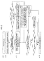
- Fig. 3 is a flowchart for explaining processing in the present embodiment. The flowchart of Fig. 3 will be described step by step below. It should be noted that this processing can be executed by a control device 50 shown in Fig. 4 .
- Fig. 4 is a diagram showing a wire-cut EDM machine (see Japanese Patent Application Laid-Open No. 2011-136409 ) including a control device.
- the control device 50 includes a central processing unit (hereinafter referred to as a CPU) 51 including a microprocessor.
- a program memory 52, a data memory 53, a control panel 54 including a liquid crystal display LCD, and an input/output device 55 are connected to the CPU 51 through a bus 56.
- the program memory 52 stores various programs for controlling various units of the wire-cut EDM machine and the control device 50 itself of the wire-cut EDM machine.
- the program memory 52 also stores a program for carrying out the present invention which is represented by the algorithm of the aforementioned flowchart.
- the data memory 53 stores position data associated with the machining program and various kinds of setting data for specifying other machining conditions.
- the data memory 53 is also used as a memory for temporarily storing data for various kinds of calculation performed by the CPU 51.
- a table driving unit 60, a machining power supply unit 61, a wire electrode blowout power supply unit 62, a wire electrode winding-back/winding-up control unit 63, a wire electrode feed control unit 64, a pulse coder 65, an electrode function switching unit 66, a wire electrode tip detection unit 67, a display device 68, and a various-unit movement control unit 69 for controlling other various units of the wire-cut EDM machine are connected to the input/output device 55.
- the table driving unit 60 and the machining power supply unit 61 include publicly-known configurations, and are respectively controlled by general ways at the time of execution of machining.
- the wire electrode blowout power supply unit 62 is configured to supply power required to blow out the wire electrode 4.
- the wire electrode winding-back/winding-up control unit 63 is configured to drive a motor (not shown) for driving a wire electrode winding-up roller and a winding-back motor (not shown).
- the wire electrode feed control unit 64 is a unit for controlling the driving of a brake motor for driving a brake roller. As described previously, the amount of rotation of the brake roller is detected by the pulse coder 65.
- the electrode function switching unit 66 is configured to select one of a wire electrode blowout electrode (wire electrode blowout unit) and wire electrode tip detection unit. A wire electrode tip detection signal from an electrode as the wire electrode tip detection unit is inputted to the wire electrode tip detection unit 67.
- the various-unit movement control unit 69 is a representation of units for controlling the advancement and retraction of a second wire electrode blowout electrode, the lowering of a wire electrode feed pipe structure at the time of automatic wire threading, and the like.
- the CPU 51 successively detects feedback pulses outputted from the pulse coder 65 when the wire electrode 4 normally runs (at the time of electrical discharge machining). When the feedback pulses are not detected for a certain period of time, the CPU 51 assumes that a break in the wire electrode 4 has occurred in an electrical discharge machining portion to stop the feed of the wire electrode 4 by the rotation of the wire electrode winding-up roller, i.e., to stop the rotation of the brake roller, and starts a wire recovery process.
- the CPU 51 which has detected the occurrence of a break in the wire electrode 4 outputs a stop command to the table driving unit 60, the machining power supply unit 61, and the wire electrode winding-back/winding-up control unit 63 to stop the feed of each axis, the supply of machining power between upper and lower electrodes for machining and the workpiece, and the driving of the wire electrode winding-up roller, and then drives the wire electrode winding-up roller for a set predetermined period of time to wind up the broken wire electrode located below the electrical discharge machining portion.
- the CPU 51 resets the value of a counter which counts feedback pulses from the pulse coder 65, switches the electrode function to the wire electrode tip detection unit, outputs a drive command to the wire electrode winding-back/winding-up control unit 63 to start the forward rotation of a supply reel, i.e., an operation for winding off the wire electrode 4, and causes the supply reel to rotate forward until a tip detection signal is inputted from the wire electrode tip detection unit 67, i.e., until the upstream-side tip of the wire electrode 4 is wound off to the position of the second wire electrode blowout electrode as the wire electrode tip detection unit.
- a tip detection signal is inputted from the wire electrode tip detection unit 67, i.e., until the upstream-side tip of the wire electrode 4 is wound off to the position of the second wire electrode blowout electrode as the wire electrode tip detection unit.
- the CPU 51 outputs a drive command to the various-unit movement control unit 69 to actuate an air cylinder so that a gripping unit positioned at a standby position in an open state may be moved to an operating position, feeds the wire electrode 4 toward a machining region by a predetermined amount by driving the brake motor and controlling the position of the brake roller based on a feedback signal from the pulse coder 65, and causes the gripping unit to be closed and grip the wire electrode 4.
- the CPU 51 switches the function of the second wire electrode blowout electrode to the wire electrode blowout unit, and actuates the wire electrode blowout power supply unit 62 to remove a portion of the wire electrode wore by electrical discharge machining.
- the wire electrode 4 is held by a flow of the machining fluid emitted from an upper nozzle 6a of the upper wire guide 5a to be guided through the machined groove 2 of the workpiece Wa or Wb and passed through the lower wire guide 5b from the a lower nozzle 6b; or, the machining fluid is drawn into the lower nozzle 6b, and the wire electrode 4 is held by the flow of the machining fluid to be guided to the lower wire guide 5b.
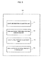
- Fig. 5 is a diagram for explaining functions of a control device of a wire-cut EDM machine in one embodiment of the present invention.
- the control device 50 includes shape information acquisition unit 71 for acquiring information on the shape of an object to be machined, wire-threading position information acquisition unit 72 for acquiring information on the wire-threading position of the wire electrode 4 based on relative positions of the upper and lower wire guides 5a and 5b, and liquid level position adjustment unit 73 for acquiring information on the height of the workpiece in the vicinity of the wire-threading position based on the workpiece shape information and adjusting the position of the liquid level of the machining fluid at the time of automatic wire threading.
- the shape information acquisition unit 71 can obtain the workpiece shape information by inputting data which associates machining positions with plate thicknesses of the workpiece (object to be machined).
- the liquid level position adjustment unit 73 adjust the position of the liquid level of the machining fluid based on the shape of the upper surface of the workpiece as well as the height of the workpiece in the vicinity of the wire-threading position at the time of automatic wire threading. Alternatively, the liquid level position adjustment unit 73 adjusts the position of the liquid level of the machining fluid in accordance with physical properties of the wire electrode 4 as well as the height of the workpiece in the vicinity of the wire-threading position at the time of automatic wire threading.
Landscapes
- Engineering & Computer Science (AREA)
- Mechanical Engineering (AREA)
- Chemical & Material Sciences (AREA)
- Chemical Kinetics & Catalysis (AREA)
- Electrochemistry (AREA)
- Automation & Control Theory (AREA)
- Electrical Discharge Machining, Electrochemical Machining, And Combined Machining (AREA)
Abstract
Description
- The present invention relates to a wire-cut electrical discharge machining (EDM) machine, and particularly to a wire-cut EDM machine in which the position of the liquid level of machining fluid is adjusted at the time of automatic wire threading.
- In wire electrical discharge machining, when a wire electrode is broken during the machining of a workpiece, returning to a machining start point and wire threading may be required. Accordingly, there is a problem that it takes a long time to perform wire threading. Meanwhile, there is a technique in which wire threading is performed at the position of occurrence of a break without returning to a machining start point in order to reduce the time required to perform a wire-threading operation. However, in the case of a workpiece having a shape with varying plate thickness, the distance from an upper nozzle to an upper surface of the workpiece varies in accordance with the position of occurrence of a break, and therefore wire-threading conditions also vary. Accordingly, depending on the position of occurrence of a break, the wire electrode is not fed straight at the time of automatic wire threading and cannot be easily passed through a machined groove. Thus, there is a problem that a reduction of wire-threading time cannot be achieved. To solve these problems, the success rate of automatic wire threading at the position of occurrence of a break needs to be improved.
- One prior art technique is a wire-cut EDM machine described in Japanese Patent Application Laid-Open No.
07-040148 - In general, in the case where automatic wire threading is performed in a wire-cut EDM machine of a type in which a wire electrode runs in a vertical direction, if the wire electrode is exposed to air until the wire electrode is inserted into a machined groove of a workpiece, the success rate of wire threading is improved. Moreover, after the wire electrode is inserted into the machined groove of the workpiece, the success rate of wire threading is improved if the wire electrode is submerged in the machining fluid.
- The prior art technique described in the section of Description of the Related Art is a technique for a wire-cut EDM machine of a type in which a wire electrode runs in a horizontal direction. If the technique is used in a wire-cut EDM machine of a type in which a wire electrode runs in a vertical direction, machining fluid is to be discharged until a lower wire guide is exposed to air. Accordingly, the workpiece is exposed to air even after the wire electrode is inserted into a machined groove of a workpiece, and the success rate of wire threading decreases. Moreover, there is another problem that it takes a long time to discharge and inject the machining fluid.
- As described above, if the height of the liquid level of the machining fluid is adjusted to a level close to the workpiece upper surface, the success rate of wire threading is high both before and after the wire electrode is inserted into the machined groove of the workpiece. However, in the case of a workpiece having a shape with varying plate thickness, the height of an upper surface of the workpiece varies in accordance with the position of wire threading. Accordingly, the height of the liquid level of machining fluid needs to be changed in accordance with the plate thickness of the workpiece.
- Accordingly, an object of the present invention is to provide a wire-cut EDM machine in which machining efficiency is improved by adjusting the height of the liquid level of machining fluid in accordance with the shape of a workpiece in the vicinity of a wire-threading position of a wire electrode to improve the success rate of wire threading for a workpiece having a shape with varying plate thickness and reduce the time required for automatic wire threading.
- A wire-cut EDM machine of the present invention, in which a position of a liquid level of machining fluid is adjusted at a time of automatic wire threading, includes a work tank for storing the machining fluid, machines an object to be machined with the object to be machined being mounted on a table provided in the work tank by moving a wire electrode stretched between upper and lower wire guides and the table relative to each other, and has an automatic wire threading function for automatically threading the wire electrode stretched between the upper and lower wire guides. The wire-cut EDM machine includes a shape information acquisition unit for acquiring information on a shape of the object to be machined; a wire-threading position information acquisition unit for acquiring information on a wire-threading position of the wire electrode based on relative positions of the upper and lower wire guides; and a liquid level position adjustment unit for acquiring a height of the object to be machined in a vicinity of the wire-threading position based on the information on the shape of the object to be machined and adjusting the position of the liquid level of the machining fluid at the time of automatic wire threading.
- The shape information acquisition unit may acquire the information on the shape of the object to be machined by inputting data which associates machining positions with plate thicknesses of the object to be machined.
- The liquid level position adjustment unit may adjust the position of the liquid level of the machining fluid at the time of automatic wire threading based on a shape of an upper surface of the object to be machined as well as the height of the object to be machined in the vicinity of the wire-threading position.
- Alternatively, the liquid level position adjustment unit may adjust the position of the liquid level of the machining fluid at the time of automatic wire threading in accordance with physical properties of the wire electrode as well as the height of the object to be machined in the vicinity of the wire-threading position.
- With the above-described configuration, the present invention can provide a wire-cut EDM machine in which machining efficiency is improved by adjusting the height of the liquid level of machining fluid in accordance with the shape of the workpiece in the vicinity of a wire-threading position of a wire electrode to improve the success rate of wire threading for a workpiece having a shape with varying plate thickness and reduce the time required for automatic wire threading.
- These and other objects and features of the present invention will become apparent from the following description of exemplary embodiments with reference to the accompanying drawings in which:
-
Fig. 1 is a view for explaining the machining of a workpiece having a shape with varying thickness; -
Fig. 2 is a view of a workpiece which is being machined, as seen from above; -
Fig. 3 is a flowchart for explaining processing according to the present invention; -
Fig. 4 is a diagram showing a wire-cut EDM machine including a control device; and -
Fig. 5 is a diagram for explaining functions of a control device of a wire-cut EDM machine according to one embodiment of the present invention. - The following embodiments are included within
claims 1 and 2. - A description will be made of the machining of a workpiece having a shape with varying thickness, such as shown in
Fig. 1 . Here, it is assumed that a workpiece Wa having a stepped shape in which plate thicknesses are h1, h2, and h3 is raised from a table 7 of a processing machine with afixture 8 by a height of h0, and an example will be described in which the height of the liquid level of machining fluid is adjusted in accordance with the height of a workpiece upper surface at a wire-threading point. Anupper nozzle 6a is assumed to be at a height separated from an uppermost surface of the workpiece Wa by a certain distance. - First, data which indicates the shape of the workpiece along a machining path, such as 3D data or data which associates machining positions with heights of the workpiece upper surface, is acquired.
- In the case where a break occurs during machining, a path along which a wire electrode 4 fed from an
upper wire guide 5a at the time of automatic wire threading passes until the wire electrode 4 is inserted into alower wire guide 5b is acquired based on the coordinates of the upper andlower wire guides - Using data on the workpiece shape and data on the path of passage of the wire electrode 4, which are acquired in the process described in the previous two paragraphs, the workpiece shape in the vicinity of the wire-threading point is checked. Then, the height of the workpiece upper surface at the wire-threading point is calculated from information on the workpiece shape, the height of the liquid level of the machining fluid is adjusted to a level close to the height of the workpiece upper surface, and an automatic wire-threading operation is performed.
- For example, in the case where wire threading is performed at points A1, A2, and A3 in
Fig. 1 , the height of the liquid level of the machining fluid is adjusted to levels close to the heights h0+h1, h0+h2, and h0+h3 of the workpiece upper surface at the wire-threading points, respectively. In the case where the height of the liquid level during machining is nearly equal to the height of the workpiece upper surface at the wire-threading point, the height of the liquid level does not need to be adjusted. - Even in a machine in which data on the shape of the workpiece Wa cannot be acquired, the height of the liquid level of the machining fluid can also be adjusted based on data on an estimated height of the workpiece upper surface at the wire-threading point, the estimated height being estimated by, for example, measuring the water pressure of the machining fluid emitted from a nozzle, feeding the wire while vibrating the wire to check the position at which the wire touches the workpiece Wa, or the like.
- Next, for a machine in which data on the shape of the workpiece Wa at an arbitrary wire-threading point cannot be acquired and in which the height of the workpiece upper surface cannot be estimated by the way described in the previous paragraph, an example will be described in which the success rate of wire threading can be improved even if the workpiece shape at the wire-threading point is unknown.
- The machining of the workpiece Wa having the shape shown in
Fig. 1 will be described. In the case of this example, it is assumed that the plate thicknesses h1 and h3 of a smallest-plate-thickness portion and a largest-plate-thickness portion can be acquired. - In the case where a break occurs during machining, the height of the liquid level of the machining fluid is adjusted to a level close to, for example, a height midway between the heights of the smallest-plate-thickness portion and the largest-plate-thickness portion (see expression (1)), and an automatic wire-threading operation is performed. In that case, the liquid level of the machining fluid cannot necessarily be adjusted to a level close to the height of the workpiece upper surface at the wire-threading point. However, the success rate of wire threading can be improved compared to that in the case where no adjustment is performed.

- The following embodiments are included within
claim 3. - The machining of a workpiece Wb having a shape shown in
Fig. 2 will be described.Fig. 2 shows the shape of the workpiece Wb during machining as seen from the upper surface thereof. This machining is performed along themachined groove 2 shown in the drawing. In the vicinity of themachined groove 2, another hole shape (hole portion 3) is assumed to exist. Moreover, the height of the workpiece upper surface is constant. Point P is a position at which a break has been detected. - In the case where a break has occurred during machining and where automatic wire threading is performed at the position of point P in
Fig. 2 , the fed wire electrode 4 may be inserted into the wrong hole in the vicinity thereof, and wire threading may end unsuccessfully. - In general, when the wire electrode 4 is fed, a machining fluid jet is emitted from the upper nozzle, and the direction in which the wire electrode 4 is fed is controlled by the fluid pressure of the jet. However, in the case where a tip of the wire electrode 4 which is being fed is in the machining fluid, the fluid pressure of the emitted jet is weakened by viscous drag, and the direction in which the wire electrode 4 is fed may be out of control.
- In cases such as this example, automatic wire threading is performed with the workpiece upper surface exposed to air by lowering the water level of the machining fluid. In that case, until the wire electrode 4 is inserted into an appropriate machined groove, the fluid pressure of the emitted jet is not weakened, and the control of the direction in which the wire electrode 4 is fed effectively works. Accordingly, the success rate of wire threading can be improved.
- The following embodiments are included within claim 4.
- As physical properties of the wire electrode 4, rigidity will be discussed. For the case where the rigidity of the wire electrode 4 is high, a method of reducing the time required for a wire-threading operation will be described in an example in which the workpiece plate thickness at the wire-threading point is small and in which the distance from the upper nozzle is long. For example, for the workpiece Wa having the shape shown in
Fig. 1 , wire threading performed at point A1, at which the plate thickness is h1, will be discussed. - First, data on the rigidity of the wire electrode 4 to be used is acquired in advance. For example, the data may be data which associates materials and wire diameters with rigidity values.
- When a break occurs during machining, if the acquired rigidity of the wire electrode 4 is lower than a threshold value set in advance, the height of the liquid level of the machining fluid is adjusted to a level close to the height h0+h1 corresponding to the workpiece upper surface. Meanwhile, if the rigidity of the wire electrode 4 is higher than the threshold value, the height of the liquid level of the machining fluid is adjusted to a level close to the height ho+h1+H obtained by adding an adjustment amount H set in advance to the height of the workpiece upper surface, and automatic wire threading is performed.
- In general, in the case where the rigidity of the wire electrode 4 is high, even if the height of the liquid level of the machining fluid is higher than a level close to h0+h1, the success rate of wire threading is high. In this example, in the case where the rigidity of the wire electrode 4 is high, the time required for the adjustment of the height of the liquid level of the machining fluid can be reduced compared to that for the case where the height of the liquid level of the machining fluid is close to h0+h1, by adjusting the height of the liquid level of the machining fluid to a position higher than a level close to the workpiece upper surface.
-
Fig. 3 is a flowchart for explaining processing in the present embodiment. The flowchart ofFig. 3 will be described step by step below. It should be noted that this processing can be executed by acontrol device 50 shown inFig. 4 . - [Step sa01] A break in the wire electrode is detected.
- [Step sa02] Information on the path along which the wire electrode passes is acquired.
- [Step sa03] A determination is made as to whether the workpiece height at the wire-threading position of the wire electrode is known or not. If the height is known (YES), the flow goes to step sa04. If the height is unknown (NO), the flow goes to step sa05.
- [Step sa04] The liquid level of the machining fluid is adjusted to a level nearly equal to the workpiece height, and the flow goes to step sa08.
- [Step sa05] A determination is made as to whether the height of the workpiece can be estimated or not. If the height can be estimated (YES), the flow goes to step sa06. If the height cannot be estimated (NO), the flow goes to step sa07.
- [Step sa06] The liquid level of the machining fluid is adjusted to a level nearly equal to the estimated workpiece height, and the flow goes to step sa08.
- [Step sa07] The liquid level of the machining fluid is adjusted to a level nearly equal to a height midway between the heights of the largest-thickness portion and the smallest-thickness portion of the workpiece, and the flow goes to step sa08.
- [Step sa08] A determination is made as to whether there is a hole shape (hole portion) in the vicinity of the wire-threading position or not. If there is a hole shape (YES), the flow goes to step sa09. If there is no hole shape (NO), the flow goes to step sa10.
- [Step sa09] The water level of the machining fluid is lowered.
- [Step sa10] A determination is made as to whether the rigidity of the wire electrode is high or not. If the rigidity is high (YES), the flow goes to step sa11. If the rigidity is not high (NO), the flow goes to step sa12.
- [Step sa11] The water level of the machining fluid is raised.
- [Step sa12] The threading of the wire electrode is executed.
-
Fig. 4 is a diagram showing a wire-cut EDM machine (see Japanese Patent Application Laid-Open No.2011-136409 control device 50 includes a central processing unit (hereinafter referred to as a CPU) 51 including a microprocessor. Aprogram memory 52, adata memory 53, acontrol panel 54 including a liquid crystal display LCD, and an input/output device 55 are connected to theCPU 51 through abus 56. - The
program memory 52 stores various programs for controlling various units of the wire-cut EDM machine and thecontrol device 50 itself of the wire-cut EDM machine. Theprogram memory 52 also stores a program for carrying out the present invention which is represented by the algorithm of the aforementioned flowchart. Moreover, thedata memory 53 stores position data associated with the machining program and various kinds of setting data for specifying other machining conditions. Thedata memory 53 is also used as a memory for temporarily storing data for various kinds of calculation performed by theCPU 51. - A
table driving unit 60, a machiningpower supply unit 61, a wire electrode blowoutpower supply unit 62, a wire electrode winding-back/winding-upcontrol unit 63, a wire electrodefeed control unit 64, apulse coder 65, an electrodefunction switching unit 66, a wire electrodetip detection unit 67, adisplay device 68, and a various-unitmovement control unit 69 for controlling other various units of the wire-cut EDM machine are connected to the input/output device 55. - The
table driving unit 60 and the machiningpower supply unit 61 include publicly-known configurations, and are respectively controlled by general ways at the time of execution of machining. The wire electrode blowoutpower supply unit 62 is configured to supply power required to blow out the wire electrode 4. The wire electrode winding-back/winding-upcontrol unit 63 is configured to drive a motor (not shown) for driving a wire electrode winding-up roller and a winding-back motor (not shown). - The wire electrode
feed control unit 64 is a unit for controlling the driving of a brake motor for driving a brake roller. As described previously, the amount of rotation of the brake roller is detected by thepulse coder 65. The electrodefunction switching unit 66 is configured to select one of a wire electrode blowout electrode (wire electrode blowout unit) and wire electrode tip detection unit. A wire electrode tip detection signal from an electrode as the wire electrode tip detection unit is inputted to the wire electrodetip detection unit 67. Further, the various-unitmovement control unit 69 is a representation of units for controlling the advancement and retraction of a second wire electrode blowout electrode, the lowering of a wire electrode feed pipe structure at the time of automatic wire threading, and the like. - The
CPU 51 successively detects feedback pulses outputted from thepulse coder 65 when the wire electrode 4 normally runs (at the time of electrical discharge machining). When the feedback pulses are not detected for a certain period of time, theCPU 51 assumes that a break in the wire electrode 4 has occurred in an electrical discharge machining portion to stop the feed of the wire electrode 4 by the rotation of the wire electrode winding-up roller, i.e., to stop the rotation of the brake roller, and starts a wire recovery process. - The
CPU 51 which has detected the occurrence of a break in the wire electrode 4 outputs a stop command to thetable driving unit 60, the machiningpower supply unit 61, and the wire electrode winding-back/winding-upcontrol unit 63 to stop the feed of each axis, the supply of machining power between upper and lower electrodes for machining and the workpiece, and the driving of the wire electrode winding-up roller, and then drives the wire electrode winding-up roller for a set predetermined period of time to wind up the broken wire electrode located below the electrical discharge machining portion. - Then, the
CPU 51 resets the value of a counter which counts feedback pulses from thepulse coder 65, switches the electrode function to the wire electrode tip detection unit, outputs a drive command to the wire electrode winding-back/winding-upcontrol unit 63 to start the forward rotation of a supply reel, i.e., an operation for winding off the wire electrode 4, and causes the supply reel to rotate forward until a tip detection signal is inputted from the wire electrodetip detection unit 67, i.e., until the upstream-side tip of the wire electrode 4 is wound off to the position of the second wire electrode blowout electrode as the wire electrode tip detection unit. - After that, based on the amount of winding off of the wire electrode 4 indicated by the value of the counter and various kinds of setting data, a portion wore by discharge is removed. Specifically, the
CPU 51 outputs a drive command to the various-unitmovement control unit 69 to actuate an air cylinder so that a gripping unit positioned at a standby position in an open state may be moved to an operating position, feeds the wire electrode 4 toward a machining region by a predetermined amount by driving the brake motor and controlling the position of the brake roller based on a feedback signal from thepulse coder 65, and causes the gripping unit to be closed and grip the wire electrode 4. - Subsequently, the
CPU 51 switches the function of the second wire electrode blowout electrode to the wire electrode blowout unit, and actuates the wire electrode blowoutpower supply unit 62 to remove a portion of the wire electrode wore by electrical discharge machining. - In an automatic wire-threading process, the wire electrode 4 is held by a flow of the machining fluid emitted from an
upper nozzle 6a of theupper wire guide 5a to be guided through the machinedgroove 2 of the workpiece Wa or Wb and passed through thelower wire guide 5b from the alower nozzle 6b; or, the machining fluid is drawn into thelower nozzle 6b, and the wire electrode 4 is held by the flow of the machining fluid to be guided to thelower wire guide 5b. -
Fig. 5 is a diagram for explaining functions of a control device of a wire-cut EDM machine in one embodiment of the present invention. Thecontrol device 50 includes shapeinformation acquisition unit 71 for acquiring information on the shape of an object to be machined, wire-threading positioninformation acquisition unit 72 for acquiring information on the wire-threading position of the wire electrode 4 based on relative positions of the upper and lower wire guides 5a and 5b, and liquid levelposition adjustment unit 73 for acquiring information on the height of the workpiece in the vicinity of the wire-threading position based on the workpiece shape information and adjusting the position of the liquid level of the machining fluid at the time of automatic wire threading. - The shape
information acquisition unit 71 can obtain the workpiece shape information by inputting data which associates machining positions with plate thicknesses of the workpiece (object to be machined). - The liquid level
position adjustment unit 73 adjust the position of the liquid level of the machining fluid based on the shape of the upper surface of the workpiece as well as the height of the workpiece in the vicinity of the wire-threading position at the time of automatic wire threading. Alternatively, the liquid levelposition adjustment unit 73 adjusts the position of the liquid level of the machining fluid in accordance with physical properties of the wire electrode 4 as well as the height of the workpiece in the vicinity of the wire-threading position at the time of automatic wire threading.
Claims (4)
- A wire-cut EDM machine in which a position of a liquid level of machining fluid is adjusted at a time of automatic wire threading, the wire-cut EDM machine including a work tank for storing the machining fluid, machining an object to be machined with the object to be machined being mounted on a table provided in the work tank by moving a wire electrode stretched between upper and lower wire guides and the table relative to each other, and having an automatic wire threading function for automatically threading the wire electrode stretched between the upper and lower wire guides, the wire-cut EDM machine comprising:a shape information acquisition unit for acquiring information on a shape of the object to be machined;a wire-threading position information acquisition unit for acquiring information on a wire-threading position of the wire electrode based on relative positions of the upper and lower wire guides; anda liquid level position adjustment unit for acquiring a height of the object to be machined in a vicinity of the wire-threading position based on the information on the shape of the object to be machined and adjusting the position of the liquid level of the machining fluid at the time of automatic wire threading.
- The wire-cut EDM machine according to claim 1, wherein the shape information acquisition unit is configured to acquire the information on the shape of the object to be machined by inputting data which associates machining positions with plate thicknesses of the object to be machined.
- The wire-cut EDM machine according to claim 1 or 2, wherein the liquid level position adjustment unit is configured to adjust the position of the liquid level of the machining fluid at the time of automatic wire threading based on a shape of an upper surface of the object to be machined as well as the height of the object to be machined in the vicinity of the wire-threading position.
- The wire-cut EDM machine according to claim 1 or 2, wherein the liquid level position adjustment unit is configured to adjust the position of the liquid level of the machining fluid at the time of automatic wire threading in accordance with physical properties of the wire electrode as well as the height of the object to be machined in the vicinity of the wire-threading position.
Applications Claiming Priority (1)
| Application Number | Priority Date | Filing Date | Title |
|---|---|---|---|
| JP2014118191A JP5911913B2 (en) | 2014-06-06 | 2014-06-06 | Wire electrical discharge machining device that adjusts the liquid level position of the machining fluid during automatic connection |
Publications (2)
| Publication Number | Publication Date |
|---|---|
| EP2952280A1 true EP2952280A1 (en) | 2015-12-09 |
| EP2952280B1 EP2952280B1 (en) | 2020-02-12 |
Family
ID=53199902
Family Applications (1)
| Application Number | Title | Priority Date | Filing Date |
|---|---|---|---|
| EP15169405.6A Active EP2952280B1 (en) | 2014-06-06 | 2015-05-27 | Wire-cut electrical discharge machining machine in which position of liquid level of machining fluid is adjusted at time of automatic wire threading |
Country Status (5)
| Country | Link |
|---|---|
| US (1) | US9884383B2 (en) |
| EP (1) | EP2952280B1 (en) |
| JP (1) | JP5911913B2 (en) |
| KR (1) | KR101748936B1 (en) |
| CN (1) | CN105269096B (en) |
Cited By (1)
| Publication number | Priority date | Publication date | Assignee | Title |
|---|---|---|---|---|
| KR20180007675A (en) * | 2016-07-13 | 2018-01-23 | 화낙 코퍼레이션 | Wire electrical discharge machine |
Families Citing this family (5)
| Publication number | Priority date | Publication date | Assignee | Title |
|---|---|---|---|---|
| WO2017072976A1 (en) * | 2015-10-30 | 2017-05-04 | 三菱電機株式会社 | Wire electric discharge machine, and control method and positioning method for control device of wire electric discharge machine |
| JP6647468B1 (en) * | 2019-04-05 | 2020-02-14 | 三菱電機株式会社 | Wire electric discharge machine |
| JP7201521B2 (en) * | 2019-04-19 | 2023-01-10 | ファナック株式会社 | Wire electric discharge machine and automatic wire connection method |
| CN112388080A (en) * | 2020-10-26 | 2021-02-23 | 浙江三奇机械设备有限公司 | Automatic cooling water tank of linear cutting equipment |
| WO2022224302A1 (en) * | 2021-04-19 | 2022-10-27 | ファナック株式会社 | Electric discharge machine |
Citations (4)
| Publication number | Priority date | Publication date | Assignee | Title |
|---|---|---|---|---|
| JPH0740148A (en) | 1993-05-27 | 1995-02-10 | Makino Milling Mach Co Ltd | Wire electric discharge machine |
| JP2008100337A (en) * | 2006-10-20 | 2008-05-01 | Mitsubishi Electric Corp | Electric discharge machining apparatus and electric discharge machining method |
| EP2340907A2 (en) * | 2010-01-04 | 2011-07-06 | Fanuc Corporation | Wire break repairing device for wire-cut electric discharge machine |
| EP2783781A2 (en) * | 2013-03-29 | 2014-10-01 | Fanuc Corporation | Wire electric discharge machine with automatic wire connecting function |
Family Cites Families (13)
| Publication number | Priority date | Publication date | Assignee | Title |
|---|---|---|---|---|
| JPS61173821A (en) * | 1985-01-24 | 1986-08-05 | Amada Co Ltd | Electric discharge machine |
| JPH01205931A (en) * | 1988-02-10 | 1989-08-18 | Amada Co Ltd | Connection of wire in wire electric discharge working machine |
| JPH0481908A (en) | 1990-07-25 | 1992-03-16 | Mitsubishi Electric Corp | Positioning method and positioning device |
| JPH06320339A (en) * | 1993-05-17 | 1994-11-22 | Fanuc Ltd | Sump wire electric discharge machine |
| US6592736B2 (en) | 2001-07-09 | 2003-07-15 | Semitool, Inc. | Methods and apparatus for controlling an amount of a chemical constituent of an electrochemical bath |
| JP2005001033A (en) * | 2003-06-10 | 2005-01-06 | Fanuc Ltd | Machining monitor |
| JP4550615B2 (en) * | 2005-02-22 | 2010-09-22 | 株式会社ソディック | Automatic wire electrode connection method |
| JP4422180B2 (en) * | 2007-12-13 | 2010-02-24 | ファナック株式会社 | Wire cut electrical discharge machine with water level abnormality detection function and method for identifying cause of water level abnormality alarm |
| JP2011062800A (en) * | 2009-09-18 | 2011-03-31 | Fanuc Ltd | Wire cut electric discharge machine controlling supply amount of working liquid into working tank and performing water temperature-constant control |
| JP4986308B2 (en) * | 2010-04-27 | 2012-07-25 | 株式会社ソディック | Automatic wire-cutting device for wire-cut electrical discharge machine |
| CN201824035U (en) * | 2010-09-21 | 2011-05-11 | 北京安德建奇数字设备有限公司 | Automatic control system for controlling machining liquid level of low-speed silk thread-tracking cutting-off machine |
| JP5225516B1 (en) * | 2011-10-13 | 2013-07-03 | 三菱電機株式会社 | Wire electrode feeder and wire electric discharge machine |
| JP5276731B1 (en) | 2012-03-21 | 2013-08-28 | ファナック株式会社 | Wire electric discharge machine with wire electrode cutting mechanism |
-
2014
- 2014-06-06 JP JP2014118191A patent/JP5911913B2/en active Active
-
2015
- 2015-05-27 EP EP15169405.6A patent/EP2952280B1/en active Active
- 2015-06-02 KR KR1020150077921A patent/KR101748936B1/en active Active
- 2015-06-05 CN CN201510306012.1A patent/CN105269096B/en active Active
- 2015-06-05 US US14/731,909 patent/US9884383B2/en not_active Expired - Fee Related
Patent Citations (5)
| Publication number | Priority date | Publication date | Assignee | Title |
|---|---|---|---|---|
| JPH0740148A (en) | 1993-05-27 | 1995-02-10 | Makino Milling Mach Co Ltd | Wire electric discharge machine |
| JP2008100337A (en) * | 2006-10-20 | 2008-05-01 | Mitsubishi Electric Corp | Electric discharge machining apparatus and electric discharge machining method |
| EP2340907A2 (en) * | 2010-01-04 | 2011-07-06 | Fanuc Corporation | Wire break repairing device for wire-cut electric discharge machine |
| JP2011136409A (en) | 2010-01-04 | 2011-07-14 | Fanuc Ltd | Wire break repairing device for wire-cut electric discharge machine |
| EP2783781A2 (en) * | 2013-03-29 | 2014-10-01 | Fanuc Corporation | Wire electric discharge machine with automatic wire connecting function |
Cited By (1)
| Publication number | Priority date | Publication date | Assignee | Title |
|---|---|---|---|---|
| KR20180007675A (en) * | 2016-07-13 | 2018-01-23 | 화낙 코퍼레이션 | Wire electrical discharge machine |
Also Published As
| Publication number | Publication date |
|---|---|
| CN105269096A (en) | 2016-01-27 |
| JP2015229236A (en) | 2015-12-21 |
| KR101748936B1 (en) | 2017-06-19 |
| US9884383B2 (en) | 2018-02-06 |
| CN105269096B (en) | 2018-04-10 |
| US20150352648A1 (en) | 2015-12-10 |
| KR20150140573A (en) | 2015-12-16 |
| EP2952280B1 (en) | 2020-02-12 |
| JP5911913B2 (en) | 2016-04-27 |
Similar Documents
| Publication | Publication Date | Title |
|---|---|---|
| EP2952280B1 (en) | Wire-cut electrical discharge machining machine in which position of liquid level of machining fluid is adjusted at time of automatic wire threading | |
| CN103167925B (en) | Wire EDM | |
| EP2641686B1 (en) | Wire electric discharge machine with wire electrode cutting mechanism | |
| JP6734321B2 (en) | Wire electric discharge machine and electric discharge method | |
| CN103286397B (en) | Wire electrical discharge machine and wire electrical discharge method for reducing machining damage | |
| EP2786825A2 (en) | Wire electric discharge machine having wire electrode tension control function | |
| EP2783781B1 (en) | Wire electric discharge machine with automatic wire connecting function and method of performing an automatic wire connection | |
| EP2617506B1 (en) | Wire electrical discharge machine carrying out electrical discharge machining by inclining wire electrode | |
| JP4904405B2 (en) | Wire break EDM machine disconnection repair device | |
| CN102341206B (en) | Wire electric-discharge-machining apparatus | |
| EP2845677B1 (en) | Numerical control apparatus for controlling wire electric discharge machine which performs taper machining | |
| WO2011049101A1 (en) | Wire electro-discharge machining device | |
| EP3581311B1 (en) | Wire electrical discharge machine and machining condition adjustment method | |
| EP3127644A1 (en) | Wire electric discharge machine | |
| CN116867594B (en) | Device and method for estimating the location of a broken wire | |
| JP2022190002A (en) | Control apparatus and control method for processing machinery | |
| TWI433744B (en) | Wire electric discharge machining apparatus | |
| US5824986A (en) | Method and apparatus for wire erosion | |
| JP2006015478A (en) | Control device for wire electric discharge machine | |
| JPH10180547A (en) | Wire electric discharge machine | |
| JP2000005935A (en) | Wire feeding method and device in wire electric discharge machining | |
| JPH0551409B2 (en) | ||
| JPS6144535A (en) | Wire-cut electric discharge machining |
Legal Events
| Date | Code | Title | Description |
|---|---|---|---|
| PUAI | Public reference made under article 153(3) epc to a published international application that has entered the european phase |
Free format text: ORIGINAL CODE: 0009012 |
|
| AK | Designated contracting states |
Kind code of ref document: A1 Designated state(s): AL AT BE BG CH CY CZ DE DK EE ES FI FR GB GR HR HU IE IS IT LI LT LU LV MC MK MT NL NO PL PT RO RS SE SI SK SM TR |
|
| AX | Request for extension of the european patent |
Extension state: BA ME |
|
| 17P | Request for examination filed |
Effective date: 20160524 |
|
| RBV | Designated contracting states (corrected) |
Designated state(s): AL AT BE BG CH CY CZ DE DK EE ES FI FR GB GR HR HU IE IS IT LI LT LU LV MC MK MT NL NO PL PT RO RS SE SI SK SM TR |
|
| STAA | Information on the status of an ep patent application or granted ep patent |
Free format text: STATUS: EXAMINATION IS IN PROGRESS |
|
| 17Q | First examination report despatched |
Effective date: 20180411 |
|
| GRAP | Despatch of communication of intention to grant a patent |
Free format text: ORIGINAL CODE: EPIDOSNIGR1 |
|
| STAA | Information on the status of an ep patent application or granted ep patent |
Free format text: STATUS: GRANT OF PATENT IS INTENDED |
|
| RIC1 | Information provided on ipc code assigned before grant |
Ipc: B23H 1/10 20060101ALN20191028BHEP Ipc: B23H 7/36 20060101ALI20191028BHEP Ipc: B23H 7/20 20060101ALI20191028BHEP Ipc: B23H 7/10 20060101AFI20191028BHEP |
|
| INTG | Intention to grant announced |
Effective date: 20191115 |
|
| GRAS | Grant fee paid |
Free format text: ORIGINAL CODE: EPIDOSNIGR3 |
|
| GRAA | (expected) grant |
Free format text: ORIGINAL CODE: 0009210 |
|
| STAA | Information on the status of an ep patent application or granted ep patent |
Free format text: STATUS: THE PATENT HAS BEEN GRANTED |
|
| AK | Designated contracting states |
Kind code of ref document: B1 Designated state(s): AL AT BE BG CH CY CZ DE DK EE ES FI FR GB GR HR HU IE IS IT LI LT LU LV MC MK MT NL NO PL PT RO RS SE SI SK SM TR |
|
| REG | Reference to a national code |
Ref country code: GB Ref legal event code: FG4D |
|
| REG | Reference to a national code |
Ref country code: CH Ref legal event code: EP Ref country code: CH Ref legal event code: NV Representative=s name: DR. LUSUARDI AG, CH |
|
| REG | Reference to a national code |
Ref country code: AT Ref legal event code: REF Ref document number: 1231445 Country of ref document: AT Kind code of ref document: T Effective date: 20200215 |
|
| REG | Reference to a national code |
Ref country code: IE Ref legal event code: FG4D |
|
| REG | Reference to a national code |
Ref country code: DE Ref legal event code: R096 Ref document number: 602015046661 Country of ref document: DE |
|
| PG25 | Lapsed in a contracting state [announced via postgrant information from national office to epo] |
Ref country code: FI Free format text: LAPSE BECAUSE OF FAILURE TO SUBMIT A TRANSLATION OF THE DESCRIPTION OR TO PAY THE FEE WITHIN THE PRESCRIBED TIME-LIMIT Effective date: 20200212 Ref country code: NO Free format text: LAPSE BECAUSE OF FAILURE TO SUBMIT A TRANSLATION OF THE DESCRIPTION OR TO PAY THE FEE WITHIN THE PRESCRIBED TIME-LIMIT Effective date: 20200512 Ref country code: RS Free format text: LAPSE BECAUSE OF FAILURE TO SUBMIT A TRANSLATION OF THE DESCRIPTION OR TO PAY THE FEE WITHIN THE PRESCRIBED TIME-LIMIT Effective date: 20200212 |
|
| REG | Reference to a national code |
Ref country code: LT Ref legal event code: MG4D |
|
| REG | Reference to a national code |
Ref country code: NL Ref legal event code: MP Effective date: 20200212 |
|
| PG25 | Lapsed in a contracting state [announced via postgrant information from national office to epo] |
Ref country code: LV Free format text: LAPSE BECAUSE OF FAILURE TO SUBMIT A TRANSLATION OF THE DESCRIPTION OR TO PAY THE FEE WITHIN THE PRESCRIBED TIME-LIMIT Effective date: 20200212 Ref country code: SE Free format text: LAPSE BECAUSE OF FAILURE TO SUBMIT A TRANSLATION OF THE DESCRIPTION OR TO PAY THE FEE WITHIN THE PRESCRIBED TIME-LIMIT Effective date: 20200212 Ref country code: HR Free format text: LAPSE BECAUSE OF FAILURE TO SUBMIT A TRANSLATION OF THE DESCRIPTION OR TO PAY THE FEE WITHIN THE PRESCRIBED TIME-LIMIT Effective date: 20200212 Ref country code: BG Free format text: LAPSE BECAUSE OF FAILURE TO SUBMIT A TRANSLATION OF THE DESCRIPTION OR TO PAY THE FEE WITHIN THE PRESCRIBED TIME-LIMIT Effective date: 20200512 Ref country code: GR Free format text: LAPSE BECAUSE OF FAILURE TO SUBMIT A TRANSLATION OF THE DESCRIPTION OR TO PAY THE FEE WITHIN THE PRESCRIBED TIME-LIMIT Effective date: 20200513 Ref country code: IS Free format text: LAPSE BECAUSE OF FAILURE TO SUBMIT A TRANSLATION OF THE DESCRIPTION OR TO PAY THE FEE WITHIN THE PRESCRIBED TIME-LIMIT Effective date: 20200612 |
|
| PG25 | Lapsed in a contracting state [announced via postgrant information from national office to epo] |
Ref country code: NL Free format text: LAPSE BECAUSE OF FAILURE TO SUBMIT A TRANSLATION OF THE DESCRIPTION OR TO PAY THE FEE WITHIN THE PRESCRIBED TIME-LIMIT Effective date: 20200212 |
|
| PG25 | Lapsed in a contracting state [announced via postgrant information from national office to epo] |
Ref country code: EE Free format text: LAPSE BECAUSE OF FAILURE TO SUBMIT A TRANSLATION OF THE DESCRIPTION OR TO PAY THE FEE WITHIN THE PRESCRIBED TIME-LIMIT Effective date: 20200212 Ref country code: SM Free format text: LAPSE BECAUSE OF FAILURE TO SUBMIT A TRANSLATION OF THE DESCRIPTION OR TO PAY THE FEE WITHIN THE PRESCRIBED TIME-LIMIT Effective date: 20200212 Ref country code: CZ Free format text: LAPSE BECAUSE OF FAILURE TO SUBMIT A TRANSLATION OF THE DESCRIPTION OR TO PAY THE FEE WITHIN THE PRESCRIBED TIME-LIMIT Effective date: 20200212 Ref country code: PT Free format text: LAPSE BECAUSE OF FAILURE TO SUBMIT A TRANSLATION OF THE DESCRIPTION OR TO PAY THE FEE WITHIN THE PRESCRIBED TIME-LIMIT Effective date: 20200705 Ref country code: LT Free format text: LAPSE BECAUSE OF FAILURE TO SUBMIT A TRANSLATION OF THE DESCRIPTION OR TO PAY THE FEE WITHIN THE PRESCRIBED TIME-LIMIT Effective date: 20200212 Ref country code: RO Free format text: LAPSE BECAUSE OF FAILURE TO SUBMIT A TRANSLATION OF THE DESCRIPTION OR TO PAY THE FEE WITHIN THE PRESCRIBED TIME-LIMIT Effective date: 20200212 Ref country code: ES Free format text: LAPSE BECAUSE OF FAILURE TO SUBMIT A TRANSLATION OF THE DESCRIPTION OR TO PAY THE FEE WITHIN THE PRESCRIBED TIME-LIMIT Effective date: 20200212 Ref country code: DK Free format text: LAPSE BECAUSE OF FAILURE TO SUBMIT A TRANSLATION OF THE DESCRIPTION OR TO PAY THE FEE WITHIN THE PRESCRIBED TIME-LIMIT Effective date: 20200212 Ref country code: SK Free format text: LAPSE BECAUSE OF FAILURE TO SUBMIT A TRANSLATION OF THE DESCRIPTION OR TO PAY THE FEE WITHIN THE PRESCRIBED TIME-LIMIT Effective date: 20200212 |
|
| REG | Reference to a national code |
Ref country code: DE Ref legal event code: R097 Ref document number: 602015046661 Country of ref document: DE |
|
| REG | Reference to a national code |
Ref country code: AT Ref legal event code: MK05 Ref document number: 1231445 Country of ref document: AT Kind code of ref document: T Effective date: 20200212 |
|
| PLBE | No opposition filed within time limit |
Free format text: ORIGINAL CODE: 0009261 |
|
| STAA | Information on the status of an ep patent application or granted ep patent |
Free format text: STATUS: NO OPPOSITION FILED WITHIN TIME LIMIT |
|
| REG | Reference to a national code |
Ref country code: DE Ref legal event code: R082 Ref document number: 602015046661 Country of ref document: DE Representative=s name: HL KEMPNER PATENTANWAELTE, SOLICITORS (ENGLAND, DE Ref country code: DE Ref legal event code: R082 Ref document number: 602015046661 Country of ref document: DE Representative=s name: HL KEMPNER PATENTANWALT, RECHTSANWALT, SOLICIT, DE Ref country code: DE Ref legal event code: R082 Ref document number: 602015046661 Country of ref document: DE Representative=s name: HL KEMPNER PARTG MBB, DE |
|
| 26N | No opposition filed |
Effective date: 20201113 |
|
| PG25 | Lapsed in a contracting state [announced via postgrant information from national office to epo] |
Ref country code: MC Free format text: LAPSE BECAUSE OF FAILURE TO SUBMIT A TRANSLATION OF THE DESCRIPTION OR TO PAY THE FEE WITHIN THE PRESCRIBED TIME-LIMIT Effective date: 20200212 Ref country code: AT Free format text: LAPSE BECAUSE OF FAILURE TO SUBMIT A TRANSLATION OF THE DESCRIPTION OR TO PAY THE FEE WITHIN THE PRESCRIBED TIME-LIMIT Effective date: 20200212 Ref country code: IT Free format text: LAPSE BECAUSE OF FAILURE TO SUBMIT A TRANSLATION OF THE DESCRIPTION OR TO PAY THE FEE WITHIN THE PRESCRIBED TIME-LIMIT Effective date: 20200212 |
|
| PG25 | Lapsed in a contracting state [announced via postgrant information from national office to epo] |
Ref country code: SI Free format text: LAPSE BECAUSE OF FAILURE TO SUBMIT A TRANSLATION OF THE DESCRIPTION OR TO PAY THE FEE WITHIN THE PRESCRIBED TIME-LIMIT Effective date: 20200212 Ref country code: PL Free format text: LAPSE BECAUSE OF FAILURE TO SUBMIT A TRANSLATION OF THE DESCRIPTION OR TO PAY THE FEE WITHIN THE PRESCRIBED TIME-LIMIT Effective date: 20200212 |
|
| REG | Reference to a national code |
Ref country code: BE Ref legal event code: MM Effective date: 20200531 |
|
| GBPC | Gb: european patent ceased through non-payment of renewal fee |
Effective date: 20200527 |
|
| PG25 | Lapsed in a contracting state [announced via postgrant information from national office to epo] |
Ref country code: LU Free format text: LAPSE BECAUSE OF NON-PAYMENT OF DUE FEES Effective date: 20200527 |
|
| PG25 | Lapsed in a contracting state [announced via postgrant information from national office to epo] |
Ref country code: IE Free format text: LAPSE BECAUSE OF NON-PAYMENT OF DUE FEES Effective date: 20200527 Ref country code: GB Free format text: LAPSE BECAUSE OF NON-PAYMENT OF DUE FEES Effective date: 20200527 Ref country code: FR Free format text: LAPSE BECAUSE OF NON-PAYMENT OF DUE FEES Effective date: 20200531 |
|
| PG25 | Lapsed in a contracting state [announced via postgrant information from national office to epo] |
Ref country code: BE Free format text: LAPSE BECAUSE OF NON-PAYMENT OF DUE FEES Effective date: 20200531 |
|
| PG25 | Lapsed in a contracting state [announced via postgrant information from national office to epo] |
Ref country code: TR Free format text: LAPSE BECAUSE OF FAILURE TO SUBMIT A TRANSLATION OF THE DESCRIPTION OR TO PAY THE FEE WITHIN THE PRESCRIBED TIME-LIMIT Effective date: 20200212 Ref country code: MT Free format text: LAPSE BECAUSE OF FAILURE TO SUBMIT A TRANSLATION OF THE DESCRIPTION OR TO PAY THE FEE WITHIN THE PRESCRIBED TIME-LIMIT Effective date: 20200212 Ref country code: CY Free format text: LAPSE BECAUSE OF FAILURE TO SUBMIT A TRANSLATION OF THE DESCRIPTION OR TO PAY THE FEE WITHIN THE PRESCRIBED TIME-LIMIT Effective date: 20200212 |
|
| PG25 | Lapsed in a contracting state [announced via postgrant information from national office to epo] |
Ref country code: MK Free format text: LAPSE BECAUSE OF FAILURE TO SUBMIT A TRANSLATION OF THE DESCRIPTION OR TO PAY THE FEE WITHIN THE PRESCRIBED TIME-LIMIT Effective date: 20200212 Ref country code: AL Free format text: LAPSE BECAUSE OF FAILURE TO SUBMIT A TRANSLATION OF THE DESCRIPTION OR TO PAY THE FEE WITHIN THE PRESCRIBED TIME-LIMIT Effective date: 20200212 |
|
| PGFP | Annual fee paid to national office [announced via postgrant information from national office to epo] |
Ref country code: DE Payment date: 20250423 Year of fee payment: 11 |
|
| PGFP | Annual fee paid to national office [announced via postgrant information from national office to epo] |
Ref country code: CH Payment date: 20250601 Year of fee payment: 11 |