EP2952273A1 - Forging device and forging method - Google Patents
Forging device and forging method Download PDFInfo
- Publication number
- EP2952273A1 EP2952273A1 EP13873655.8A EP13873655A EP2952273A1 EP 2952273 A1 EP2952273 A1 EP 2952273A1 EP 13873655 A EP13873655 A EP 13873655A EP 2952273 A1 EP2952273 A1 EP 2952273A1
- Authority
- EP
- European Patent Office
- Prior art keywords
- workpiece
- shaping roller
- axis
- central
- forging
- Prior art date
- Legal status (The legal status is an assumption and is not a legal conclusion. Google has not performed a legal analysis and makes no representation as to the accuracy of the status listed.)
- Withdrawn
Links
- 238000005242 forging Methods 0.000 title claims abstract description 88
- 238000000034 method Methods 0.000 title claims description 20
- 238000007493 shaping process Methods 0.000 claims abstract description 140
- 230000002093 peripheral effect Effects 0.000 claims abstract description 67
- 238000000465 moulding Methods 0.000 description 32
- 239000000463 material Substances 0.000 description 16
- 230000004048 modification Effects 0.000 description 10
- 238000012986 modification Methods 0.000 description 10
- 238000004519 manufacturing process Methods 0.000 description 5
- 230000005540 biological transmission Effects 0.000 description 3
- 238000010276 construction Methods 0.000 description 2
- 238000007796 conventional method Methods 0.000 description 2
- 230000000694 effects Effects 0.000 description 2
- 229910000831 Steel Inorganic materials 0.000 description 1
- 229910001315 Tool steel Inorganic materials 0.000 description 1
- 239000011248 coating agent Substances 0.000 description 1
- 238000000576 coating method Methods 0.000 description 1
- 239000002184 metal Substances 0.000 description 1
- 239000007787 solid Substances 0.000 description 1
- 239000010959 steel Substances 0.000 description 1
- 238000005482 strain hardening Methods 0.000 description 1
Images






Classifications
-
- B—PERFORMING OPERATIONS; TRANSPORTING
- B21—MECHANICAL METAL-WORKING WITHOUT ESSENTIALLY REMOVING MATERIAL; PUNCHING METAL
- B21J—FORGING; HAMMERING; PRESSING METAL; RIVETING; FORGE FURNACES
- B21J5/00—Methods for forging, hammering, or pressing; Special equipment or accessories therefor
- B21J5/06—Methods for forging, hammering, or pressing; Special equipment or accessories therefor for performing particular operations
-
- B—PERFORMING OPERATIONS; TRANSPORTING
- B21—MECHANICAL METAL-WORKING WITHOUT ESSENTIALLY REMOVING MATERIAL; PUNCHING METAL
- B21D—WORKING OR PROCESSING OF SHEET METAL OR METAL TUBES, RODS OR PROFILES WITHOUT ESSENTIALLY REMOVING MATERIAL; PUNCHING METAL
- B21D22/00—Shaping without cutting, by stamping, spinning, or deep-drawing
- B21D22/14—Spinning
- B21D22/16—Spinning over shaping mandrels or formers
-
- B—PERFORMING OPERATIONS; TRANSPORTING
- B21—MECHANICAL METAL-WORKING WITHOUT ESSENTIALLY REMOVING MATERIAL; PUNCHING METAL
- B21D—WORKING OR PROCESSING OF SHEET METAL OR METAL TUBES, RODS OR PROFILES WITHOUT ESSENTIALLY REMOVING MATERIAL; PUNCHING METAL
- B21D53/00—Making other particular articles
- B21D53/26—Making other particular articles wheels or the like
-
- B—PERFORMING OPERATIONS; TRANSPORTING
- B21—MECHANICAL METAL-WORKING WITHOUT ESSENTIALLY REMOVING MATERIAL; PUNCHING METAL
- B21K—MAKING FORGED OR PRESSED METAL PRODUCTS, e.g. HORSE-SHOES, RIVETS, BOLTS OR WHEELS
- B21K21/00—Making hollow articles not covered by a single preceding sub-group
- B21K21/16—Remodelling hollow bodies with respect to the shape of the cross-section
-
- B—PERFORMING OPERATIONS; TRANSPORTING
- B21—MECHANICAL METAL-WORKING WITHOUT ESSENTIALLY REMOVING MATERIAL; PUNCHING METAL
- B21K—MAKING FORGED OR PRESSED METAL PRODUCTS, e.g. HORSE-SHOES, RIVETS, BOLTS OR WHEELS
- B21K23/00—Making other articles
- B21K23/04—Making other articles flanged articles
-
- B—PERFORMING OPERATIONS; TRANSPORTING
- B21—MECHANICAL METAL-WORKING WITHOUT ESSENTIALLY REMOVING MATERIAL; PUNCHING METAL
- B21H—MAKING PARTICULAR METAL OBJECTS BY ROLLING, e.g. SCREWS, WHEELS, RINGS, BARRELS, BALLS
- B21H1/00—Making articles shaped as bodies of revolution
- B21H1/02—Making articles shaped as bodies of revolution discs; disc wheels
Definitions
- the present invention relates to a forging device and a forging method each of which performs molding such that a shaping roller is pressed against a workpiece so as to expand the workpiece in a radial direction and a central-axis direction of the workpiece.
- Patent Document 1 describes a forging method for performing diameter expansion molding to expand a cylindrical metal workpiece in a radial direction of the workpiece.
- the workpiece is rotated around a central axis of the workpiece, and a cylindrical shaping roller is pressed against that end surface of the workpiece thus rotated which is on one side in a central-axis direction of the workpiece.
- the shaping roller makes contact with the workpiece as such, and then, the shaping roller is moved down with the shaping roller being rotated with the workpiece.
- a pressure is applied to the workpiece from the shaping roller, so that the workpiece can be expanded in the radial direction.
- Patent Document 1 Japanese Patent Application Publication No. 2011-224605 ( JP 2011-224605 A )
- an object of the present invention is to provide a forging device and a forging method each of which can manufacture a forging having a boss portion while achieving reduction in cost.
- One aspect of the present invention to solve the above problems is characterized in that: in a forging device including a rotating table that rotates around a rotation axis, and a cylindrical shaping roller, the forging device forging a cylindrical workpiece such that an outer peripheral surface of the shaping roller is pressed against an end surface of the workpiece in a central-axis direction of the workpiece while the workpiece is rotated by the rotating table around a central axis of the workpiece, the shaping roller is placed apart from the rotation axis, and a position of that end of the outer peripheral surface of the shaping roller which is opposite to a rotation-axis side in a central-axis direction of the shaping roller is placed at an outer side in a radial direction of the workpiece relative to a position of an outer peripheral surface of the workpiece that has been forged.
- the above aspect it is possible to perform diameter expansion molding to expand the cylindrical workpiece in the radial direction such that the outer peripheral surface of the shaping roller is pressed against the end surface of the workpiece in the central-axis direction of the workpiece while the workpiece is rotated by the rotating table around the central axis of the workpiece. Further, since the shaping roller is placed apart from the rotation axis of the rotating table, a material of the workpiece flows toward the rotation-axis side relative to the shaping roller, so that boss molding to form a boss portion formed by raising a central part of the workpiece in the central-axis direction of the workpiece can be performed. Thus, the diameter expansion molding and the boss molding can be performed at the same time. This makes it possible to manufacture a forging having the boss portion while achieving reduction in cost.
- the position of that end of the outer peripheral surface of the shaping roller which is opposite to the rotation-axis side in the central-axis direction of the shaping roller is placed at the outer side in the radial direction of the workpiece relative to the position of the outer peripheral surface of the workpiece that has been forged.
- This causes such a state where the outer peripheral surface of the shaping roller is pressed against a large area of the end surface of the workpiece in the central-axis direction of the workpiece, during the forging of the workpiece.
- This makes it possible to secure accuracy of the end surface of the workpiece that has been forged, by the outer peripheral surface of the shaping roller. This can accordingly improve the accuracy of the end surface of the workpiece that has been forged.
- the forging device include a cylindrical mandrel; a central axis of the mandrel accord with the rotation axis; the shaping roller have an inner end surface placed at the rotation-axis side in the central-axis direction of the shaping roller; and a distance between the central axis of the mandrel and the inner end surface be larger than a radius of the mandrel but smaller than a radius of the workpiece.
- the boss portion having a hollow cylindrical shape in the central part of the workpiece. Since the material of the workpiece flows while making close contact with the outer peripheral surface of the mandrel, it is possible to secure desired accuracy in an inner peripheral surface of the boss portion by managing accuracy of the outer peripheral surface of the mandrel.
- the forging device include two shaping rollers.
- a central axis of the shaping roller be generally perpendicular to the rotation axis.
- the two shaping rollers can be integrated with each other by one shaft member while central axes of the two shaping rollers accord with each other. This makes it possible to simplify the mechanism for supporting the two shaping rollers.
- Another aspect of the present invention to solve the above problems is characterized in that: in a forging method for forging a cylindrical workpiece, by use of a rotating table that rotates around a rotation axis, and a cylindrical shaping roller, such that an outer peripheral surface of the shaping roller is pressed against an end surface of the workpiece in a central-axis direction of the workpiece while the workpiece is rotated by the rotating table around a central axis of the workpiece, the shaping roller is placed apart from the rotation axis, and a position of that end of the outer peripheral surface of the shaping roller which is opposite to a rotation-axis side in the central-axis direction of the shaping roller is placed at an outer side in a radial direction of the workpiece relative to a position of an outer peripheral surface of the workpiece that has been forged.
- the above aspect it is possible to perform diameter expansion molding to expand the cylindrical workpiece in the radial direction such that the outer peripheral surface of the shaping roller is pressed against the end surface of the workpiece in the central-axis direction of the workpiece while the workpiece is rotated by the rotating table around the central axis of the workpiece. Further, since the shaping roller is placed apart from the rotation axis of the rotating table, a material of the workpiece flows toward the rotation-axis side relative to the shaping roller, so that boss molding to form a boss portion formed by raising a central part of the workpiece in the central-axis direction of the workpiece can be performed. Thus, the diameter expansion molding and the boss molding can be performed at the same time. This makes it possible to manufacture a forging having the boss portion while achieving reduction in cost.
- the position of that end of the outer peripheral surface of the shaping roller which is opposite to the rotation-axis side in the central-axis direction of the shaping roller is placed at the outer side in the radial direction of the workpiece relative to the position of the outer peripheral surface of the workpiece that has been forged.
- This causes such a state where the outer peripheral surface of the shaping roller is pressed against a large area of the end surface of the workpiece in the central-axis direction of the workpiece, during the forging of the workpiece.
- This makes it possible to secure accuracy of the end surface of the workpiece that has been forged, by the outer peripheral surface of the shaping roller. This can accordingly improve the accuracy of the end surface of the workpiece that has been forged.
- a cylindrical mandrel be used; a central axis of the mandrel accord with the rotation axis; the shaping roller have an inner end surface placed at the rotation-axis side in the central-axis direction of the shaping roller; and a distance between the central axis of the mandrel and the inner end surface be larger than a radius of the mandrel but smaller than a radius of the workpiece.
- the boss portion having a hollow cylindrical shape in the central part of the workpiece. Since the material of the workpiece flows while making close contact with the outer peripheral surface of the mandrel, it is possible to secure desired accuracy in an inner peripheral surface of the boss portion by managing accuracy of the outer peripheral surface of the mandrel.
- a central axis of the shaping roller be generally perpendicular to the rotation axis.
- the two shaping rollers can be integrated with each other by one shaft member while central axes of the two shaping rollers accord with each other. This makes it possible to simplify the mechanism for supporting the two shaping rollers.
- the forging device and the forging method of the present invention it is possible to manufacture a forging having a boss portion while achieving reduction in cost.
- FIGS. 1 and 2 are each a sectional view illustrating a schematic configuration of the forging device 1 of the present embodiment.
- FIG. 1 illustrates a state before forging is performed on a workpiece W
- FIG. 2 illustrates a state after the forging is performed on the workpiece W.
- the forging device 1 includes a rotating table 10, a mandrel 12, a shaping roller 14, roller moving means (not shown), and so on.
- the rotating table 10 rotates around a rotation axis L1. Further, the rotating table 10 rotates the workpiece W placed on a surface 10a, around a central axis of the workpiece W.
- the mandrel 12 is formed in a cylindrical shape.
- the mandrel 12 is placed on the surface 10a of the rotating table 10 so that a central axis of the mandrel 12 accords with the rotation axis L1 of the rotating table 10.
- the mandrel 12 is inserted inside an inner peripheral surface Wa of the workpiece W, and the workpiece W is placed on the surface 10a of the rotating table 10 with an outer peripheral surface 12a of the mandrel 12 making contact with the inner peripheral surface Wa of the workpiece W.
- the shaping roller 14 is formed in a cylindrical shape. Further, the shaping roller 14 includes an outer peripheral surface 14a, an inner end surface 14b, and so on.
- the inner end surface 14b is an end surface on a rotation-axis-L1 side in a central-axis-L2 direction of the shaping roller 14.
- two shaping rollers 14 are provided.
- the two shaping rollers 14 are placed at respective positions whose phases are shifted by 180° to each other in a rotation direction of the rotating table 10.
- the two shaping rollers 14 are integrated with each other by a shaft 20 in such a state where their central axes L2 accord with each other.
- the shaft 20 is attached to a housing 22 in a rotatable state. Because of this, the two shaping rollers 14 integrated with each other by the shaft 20 rotate integrally around the central axes L2 of the shaping rollers 14.
- the shaping roller 14 is placed apart from the rotation axis L1. That is, a gap is provided between the rotation axis L1 and the inner end surface 14b of the shaping roller 14 (more specifically, an intersection of the inner end surface 14b with the central axis L2). A distance ⁇ 0 between the rotation axis L1 and the inner end surface 14b is larger than a radius r of the mandrel 12, but smaller than a radius R0 of the workpiece W.
- the central axis L2 of the shaping roller 14 is generally perpendicular to the rotation axis L1. More specifically, the central axis L2 intersects with the rotation axis L1 at an angle of 90° ⁇ 10° (that is, 80° to 100°), for example.
- materials of the rotating table 10, the mandrel 12, and the shaping roller 14 may be cold working tool steel (SKD11, SKH), cemented carbide, and the like, for example.
- the outer peripheral surface 14a of the shaping roller 14 is a part that makes contact with the workpiece W, which will be described later. On this account, it is desirable that coating be performed on the outer peripheral surface 14a of the shaping roller 14 so as to maintain a surface state.
- roller moving means is attached to the housing 22.
- the roller moving means moves the housing 22 in parallel along a rotation-axis-L1 direction of the rotating table 10, so as to move the two shaping rollers 14 in parallel to the rotation axis L1.
- the roller moving means is a ball screw, a hydraulic mechanism, or the like, for example.
- the forging device 1 includes a controlling portion (not shown).
- the controlling portion is constituted by a microcomputer, for example, and controls driving of the rotating table 10, the roller moving means, and so on.
- the workpiece W having a hollow cylindrical shape is placed on the surface 10a of the rotating table 10.
- the mandrel 12 is inserted inside the inner peripheral surface Wa of the workpiece W so that the central axis of the workpiece W accords with the rotation axis L1 of the rotating table 10.
- a height H (a length in the rotation-axis-L1 direction) of the mandrel 12 is larger than a height h (a length in the rotation-axis-L1 direction) of the workpiece W.
- the rotating table 10 and the mandrel 12 are rotated around the rotation axis L1 (the central axis of the mandrel 12, the central axis of the workpiece W).
- the workpiece W is rotated around the rotation axis L1.
- the shaping roller 14 is moved toward the workpiece W by the roller moving means. Then, the outer peripheral surface 14a of the shaping roller 14 is pressed against an end surface Wb of the workpiece W (an end surface thereof at a shaping-roller-14 side in the central-axis direction of the workpiece W), so that the shaping roller 14 makes contact with the workpiece W.
- the workpiece W is being rotated around the rotation axis L1. Because of this, when the shaping roller 14 makes contact with the workpiece W as described above, the shaping roller 14 rotates following the workpiece W. That is, the shaping roller 14 rotates around the central axis L2.
- the shaping roller 14 is moved toward the workpiece W by the roller moving means. This causes a pressure to be applied to the end surface Wb of the workpiece W from the shaping roller 14, so that the workpiece W expands outwardly in a radial direction of the workpiece W.
- diameter expansion molding is performed on the workpiece W.
- the distance ⁇ 0 between the rotation axis L1 of the rotating table 10 (the central axis of the workpiece W) and the inner end surface 14b of the shaping roller 14 is larger than the radius r of the mandrel 12, but smaller than the radius R0 (see FIG. 1 ) of the workpiece W before the workpiece W is forged and a radius R1 (see FIG. 2 ) of the workpiece W after the workpiece W is forged.
- the shaping roller 14 is separated from the mandrel 12, as illustrated in FIG. 2 .
- the outer peripheral surface 12a of the mandrel 12 is separated from the inner end surface 14b of the shaping roller 14 by a distance ⁇ 1, so that a gap is provided between the outer peripheral surface 12a of the mandrel 12 and the inner end surface 14b of the shaping roller 14. Because of this, when a pressure is applied to the end surface Wb of the workpiece W from the shaping roller 14 as described above, a radially inner part of the workpiece W is raised toward a shaping-roller-14 side in the rotation-axis-L1 direction, as illustrated in FIG. 2 . Hereby, a boss portion Wc raised in the central-axis direction of the workpiece W is formed at a central part of the workpiece W. Thus, boss molding is performed on the workpiece W.
- the shaping roller 14 revolves around the rotation axis L1 of the rotating table 10 as illustrated in FIG. 3 , when viewed from the workpiece W.
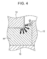
- a material of the workpiece W flows toward an outer-peripheral-surface-Wd side of the workpiece W so that the material is scraped off, as illustrated in FIG. 4 , and also flows toward a rotation-axis-L1 side (a mandrel-12 side).
- the diameter expansion molding to expand the workpiece W in the radial direction of the workpiece W is performed. Further, when the material of the workpiece W flows toward the rotation-axis-L1 side (the mandrel-12 side), the material of the workpiece W flows to the central-axis direction of the workpiece W along the outer peripheral surface 12a of the mandrel 12. Hereby, the boss molding to form the boss portion Wc is performed.
- a position of an outer end 104 on a shaping surface 102 of a shaping roller 100 is placed at an inner side in a radial direction of the workpiece W relative to a position of an outer periphery WOb of the workpiece W0, as illustrated in FIG. 5 .
- a position of that outer end 14c of the outer peripheral surface 14a of the shaping roller 14 which is opposite to the rotation-axis-L1 side in the central-axis-L2 direction is placed at an outer side in the radial direction of the workpiece W relative to a position of the outer peripheral surface Wd of the workpiece W that has been forged, as illustrated in FIG. 2 .
- This causes such a state where the outer peripheral surface 14a of the shaping roller 14 is pressed against a large area of the end surface Wb of the workpiece W in the radial direction of the workpiece W, from the beginning of the forging of the workpiece W to the end of the forging.
- This makes it possible to secure accuracy of the end surface Wb of the workpiece W that has been forged, by the outer peripheral surface 14a of the shaping roller 14. This accordingly improves accuracy of the end surface Wb of the workpiece W that has been forged.
- the forging device 1 can perform the diameter expansion molding and the boss molding at a low load.
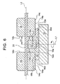
- FIG. 6 such an example in which a mandrel 12 is provided separately from a rotating table 10 can be considered, as illustrated in FIG. 6 .
- FIG. 7 such an example in which a surface 10a of a rotating table 10 is formed as an inclined surface, and an outer peripheral surface 14a of a shaping roller 14 is formed to be inclined relative to a central axis L2 can be also considered.
- splines may be formed on an outer peripheral surface 12a of a mandrel 12. This makes it possible to form a boss portion Wc while forming splines on an inner peripheral surface Wa of a workpiece W.
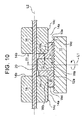
- FIG. 10 such an example in which a surface 10a of a rotating table 10 is formed to have a waveform shape.
- FIG. 11 a forging device that does not include a mandrel 12 can be considered, as illustrated in FIG. 11 .
- a workpiece W that has not been forged yet is formed in a solid cylindrical shape.
- FIGS. 6 to 8 , 10 , and 11 partially illustrate a forging device.
- the forging device 1 which includes the rotating table 10 that rotates around the rotation axis L1, and the cylindrical shaping roller 14, and which forges the cylindrical workpiece W such that the outer peripheral surface 14a of the shaping roller 14 is pressed against the end surface Wb of the workpiece W in the central-axis direction of the workpiece W while the workpiece W is rotated by the rotating table 10 around the central axis of the workpiece W
- the shaping roller 14 is placed apart from the rotation axis L1, and the position of that outer end 14c of the outer peripheral surface 14a of the shaping roller 14 which is opposite to the rotation-axis-L1 side in the central-axis-L2 direction of the shaping roller 14 is placed at the outer side in the radial direction of the workpiece W relative to the position of the outer peripheral surface Wd of the workpiece W that has been forged.
- the diameter expansion molding to expand the cylindrical workpiece W in the radial direction can be performed such that the outer peripheral surface 14a of the shaping roller 14 is pressed against the end surface Wb of the workpiece W in the central-axis-L2 direction of the workpiece W while the workpiece W is rotated by the rotating table 10 around the central axis of the workpiece W.
- the shaping roller 14 since the shaping roller 14 is placed apart from the rotation axis L1 of the rotating table 10, the material of the workpiece W flows toward the rotation-axis-L1 side relative to the shaping roller 14, so that the boss molding to form the boss portion Wc formed by raising a central part of the workpiece W in the central-axis direction of the workpiece W can be performed.
- the diameter expansion molding and the boss molding can be performed at the same time. This makes it possible to manufacture a forging having the boss portion Wc while achieving reduction in cost.
- the position of that outer end 14c of the outer peripheral surface 14a of the shaping roller 14 which is opposite to the rotation-axis-L1 side of the rotating table 10 in the central-axis-L2 direction of the shaping roller 14 is placed at the outer side in the radial direction of the workpiece W relative to the position of the outer peripheral surface Wd of the workpiece W that has been forged.
- This causes such a state where the outer peripheral surface 14a of the shaping roller 14 is pressed against a large area of the end surface Wb of the workpiece W, in the central-axis direction of the workpiece W, during the forging of the workpiece W.
- This makes it possible to secure accuracy of the end surface Wb of the workpiece W that has been forged, by the outer peripheral surface 14a of the shaping roller 14. This can accordingly improve the accuracy of the end surface Wb of the workpiece W that has been forged.
- the forging device 1 include the cylindrical mandrel 12; the central axis of the mandrel 12 accord with the rotation axis L1 of the rotating table 10; the shaping roller 14 have the inner end surface 14b placed at the rotation-axis-L1 side in the central-axis-L2 direction of the shaping roller 14; and the distance ⁇ 1 between the central axis of the mandrel 12 and the inner end surface 14b be larger than the radius of the mandrel 12, but smaller than the radius of the workpiece.
- the boss portion Wc having a hollow cylindrical shape in the central part of the workpiece W. Since the material of the workpiece W flows while making close contact with the outer peripheral surface 12a of the mandrel 12, it is possible to secure desired accuracy on an inner peripheral surface of the boss portion Wc by managing accuracy of the outer peripheral surface 12a of the mandrel 12.
- the forging device 1 includes two shaping rollers 14, it is possible to shorten a time to forge the workpiece W. Also, the accuracy of the end surface Wb of the workpiece W is improved.
- the central axis L2 of the shaping roller 14 is generally perpendicular to the rotation axis L1 of the rotating table 10. This makes it possible to simplify a mechanism for supporting the shaping roller 14.
- the two shaping rollers 14 can be integrated with each other by one shaft 20 while central axes of the two shaping rollers 14 accord with each other. This accordingly makes it possible to simplify the mechanism for supporting the two shaping rollers 14. Accordingly, the two shaping rollers 14 can be easily handled. Further, a force that can be added to the workpiece W from the shaping rollers 14 can be increased. Also, rigidity of the shaping rollers 14 can be obtained.
- a forging manufactured by the forging device 1 and the forging method of the present invention is suitable for a power transmission component.
- the forging is most suitable for steel components used for power transmission, such as a gear wheel and a shaft used in an automobile, a construction vehicle, a construction machine, and the like, and particularly, a transmission gear wheel of an automobile and a sheave of CVT.
Landscapes
- Engineering & Computer Science (AREA)
- Mechanical Engineering (AREA)
- Forging (AREA)
- Shaping Metal By Deep-Drawing, Or The Like (AREA)
Abstract
Description
- The present invention relates to a forging device and a forging method each of which performs molding such that a shaping roller is pressed against a workpiece so as to expand the workpiece in a radial direction and a central-axis direction of the workpiece.
-
Patent Document 1 describes a forging method for performing diameter expansion molding to expand a cylindrical metal workpiece in a radial direction of the workpiece. In the forging method ofPatent Document 1, the workpiece is rotated around a central axis of the workpiece, and a cylindrical shaping roller is pressed against that end surface of the workpiece thus rotated which is on one side in a central-axis direction of the workpiece. The shaping roller makes contact with the workpiece as such, and then, the shaping roller is moved down with the shaping roller being rotated with the workpiece. Hereby, a pressure is applied to the workpiece from the shaping roller, so that the workpiece can be expanded in the radial direction. - Patent Document 1: Japanese Patent Application Publication No.
2011-224605 JP 2011-224605 A - However, in the forging method of
Patent Document 1, although it is possible to perform diameter expansion molding to expand the workpiece in the radial direction of the workpiece, it is difficult to perform boss molding to form a boss portion formed by raising a central part of the workpiece in the central-axis direction of the workpiece. In view of this, it is necessary to separately perform a step of performing the boss molding after a step of performing diameter expansion molding is performed first by the forging method ofPatent Document 1. Accordingly, different forging devices are required for respective steps at the time when a forging having a boss portion is manufactured, which increases cost. - In view of this, the present invention has been accomplished in order to solve the above problems, and an object of the present invention is to provide a forging device and a forging method each of which can manufacture a forging having a boss portion while achieving reduction in cost.
- One aspect of the present invention to solve the above problems is characterized in that: in a forging device including a rotating table that rotates around a rotation axis, and a cylindrical shaping roller, the forging device forging a cylindrical workpiece such that an outer peripheral surface of the shaping roller is pressed against an end surface of the workpiece in a central-axis direction of the workpiece while the workpiece is rotated by the rotating table around a central axis of the workpiece, the shaping roller is placed apart from the rotation axis, and a position of that end of the outer peripheral surface of the shaping roller which is opposite to a rotation-axis side in a central-axis direction of the shaping roller is placed at an outer side in a radial direction of the workpiece relative to a position of an outer peripheral surface of the workpiece that has been forged.
- According to the above aspect, it is possible to perform diameter expansion molding to expand the cylindrical workpiece in the radial direction such that the outer peripheral surface of the shaping roller is pressed against the end surface of the workpiece in the central-axis direction of the workpiece while the workpiece is rotated by the rotating table around the central axis of the workpiece. Further, since the shaping roller is placed apart from the rotation axis of the rotating table, a material of the workpiece flows toward the rotation-axis side relative to the shaping roller, so that boss molding to form a boss portion formed by raising a central part of the workpiece in the central-axis direction of the workpiece can be performed. Thus, the diameter expansion molding and the boss molding can be performed at the same time. This makes it possible to manufacture a forging having the boss portion while achieving reduction in cost.
- Further, the position of that end of the outer peripheral surface of the shaping roller which is opposite to the rotation-axis side in the central-axis direction of the shaping roller is placed at the outer side in the radial direction of the workpiece relative to the position of the outer peripheral surface of the workpiece that has been forged. This causes such a state where the outer peripheral surface of the shaping roller is pressed against a large area of the end surface of the workpiece in the central-axis direction of the workpiece, during the forging of the workpiece. This makes it possible to secure accuracy of the end surface of the workpiece that has been forged, by the outer peripheral surface of the shaping roller. This can accordingly improve the accuracy of the end surface of the workpiece that has been forged.
- In the forging device, it is preferable that: the forging device include a cylindrical mandrel; a central axis of the mandrel accord with the rotation axis; the shaping roller have an inner end surface placed at the rotation-axis side in the central-axis direction of the shaping roller; and a distance between the central axis of the mandrel and the inner end surface be larger than a radius of the mandrel but smaller than a radius of the workpiece.
- According to the above aspect, by flowing the material of the workpiece between the outer peripheral surface of the mandrel and the inner end surface of the shaping roller, it is possible to form the boss portion having a hollow cylindrical shape in the central part of the workpiece. Since the material of the workpiece flows while making close contact with the outer peripheral surface of the mandrel, it is possible to secure desired accuracy in an inner peripheral surface of the boss portion by managing accuracy of the outer peripheral surface of the mandrel.
- It is preferable that the forging device include two shaping rollers.
- According to the above aspect, it is possible to shorten a time to forge the workpiece. Also, the accuracy of the end surface of the workpiece is improved.
- In the forging device, it is preferable that a central axis of the shaping roller be generally perpendicular to the rotation axis.
- According to the above aspect, it is possible to simplify a mechanism for supporting the shaping roller. Particularly, in a case where two shaping rollers are provided, the two shaping rollers can be integrated with each other by one shaft member while central axes of the two shaping rollers accord with each other. This makes it possible to simplify the mechanism for supporting the two shaping rollers.
- Another aspect of the present invention to solve the above problems is characterized in that: in a forging method for forging a cylindrical workpiece, by use of a rotating table that rotates around a rotation axis, and a cylindrical shaping roller, such that an outer peripheral surface of the shaping roller is pressed against an end surface of the workpiece in a central-axis direction of the workpiece while the workpiece is rotated by the rotating table around a central axis of the workpiece, the shaping roller is placed apart from the rotation axis, and a position of that end of the outer peripheral surface of the shaping roller which is opposite to a rotation-axis side in the central-axis direction of the shaping roller is placed at an outer side in a radial direction of the workpiece relative to a position of an outer peripheral surface of the workpiece that has been forged.
- According to the above aspect, it is possible to perform diameter expansion molding to expand the cylindrical workpiece in the radial direction such that the outer peripheral surface of the shaping roller is pressed against the end surface of the workpiece in the central-axis direction of the workpiece while the workpiece is rotated by the rotating table around the central axis of the workpiece. Further, since the shaping roller is placed apart from the rotation axis of the rotating table, a material of the workpiece flows toward the rotation-axis side relative to the shaping roller, so that boss molding to form a boss portion formed by raising a central part of the workpiece in the central-axis direction of the workpiece can be performed. Thus, the diameter expansion molding and the boss molding can be performed at the same time. This makes it possible to manufacture a forging having the boss portion while achieving reduction in cost.
- Further, the position of that end of the outer peripheral surface of the shaping roller which is opposite to the rotation-axis side in the central-axis direction of the shaping roller is placed at the outer side in the radial direction of the workpiece relative to the position of the outer peripheral surface of the workpiece that has been forged. This causes such a state where the outer peripheral surface of the shaping roller is pressed against a large area of the end surface of the workpiece in the central-axis direction of the workpiece, during the forging of the workpiece. This makes it possible to secure accuracy of the end surface of the workpiece that has been forged, by the outer peripheral surface of the shaping roller. This can accordingly improve the accuracy of the end surface of the workpiece that has been forged.
- In the forging method, it is preferable that: a cylindrical mandrel be used; a central axis of the mandrel accord with the rotation axis; the shaping roller have an inner end surface placed at the rotation-axis side in the central-axis direction of the shaping roller; and a distance between the central axis of the mandrel and the inner end surface be larger than a radius of the mandrel but smaller than a radius of the workpiece.
- According to the above aspect, by flowing the material of the workpiece between the outer peripheral surface of the mandrel and the inner end surface of the shaping roller, it is possible to form the boss portion having a hollow cylindrical shape in the central part of the workpiece. Since the material of the workpiece flows while making close contact with the outer peripheral surface of the mandrel, it is possible to secure desired accuracy in an inner peripheral surface of the boss portion by managing accuracy of the outer peripheral surface of the mandrel.
- In the forging method, it is preferable that two shaping rollers be used.
- According to the above aspect, it is possible to shorten a time to forge the workpiece. Also, the accuracy of the end surface of the workpiece is improved.
- In the forging method, it is preferable that a central axis of the shaping roller be generally perpendicular to the rotation axis.
- According to the above aspect, it is possible to simplify a mechanism for supporting the shaping roller. Particularly, in a case where two shaping rollers are provided, the two shaping rollers can be integrated with each other by one shaft member while central axes of the two shaping rollers accord with each other. This makes it possible to simplify the mechanism for supporting the two shaping rollers.
- According to the forging device and the forging method of the present invention, it is possible to manufacture a forging having a boss portion while achieving reduction in cost.
-
- [
FIG. 1] FIG. 1 is a sectional view illustrating a schematic configuration of a forging device of the present embodiment, and illustrates a state before forging is performed on a workpiece. - [
FIG. 2] FIG. 2 is a sectional view illustrating the schematic configuration of the forging device of the present embodiment, and illustrates a state after the forging is performed on the workpiece. - [
FIG. 3] FIG. 3 is a view to describe a principle to perform diameter expansion molding and boss molding on the workpiece. - [
FIG. 4] FIG. 4 is a sectional view taken along a line A-A inFIG. 3 . - [
FIG. 5] FIG. 5 is a view to describe a conventional technique. - [
FIG. 6] FIG. 6 is a sectional view illustrating a schematic configuration of a forging device of a modification. - [
FIG. 7] FIG. 7 is a sectional view illustrating a schematic configuration of a forging device of a modification. - [
FIG. 8] FIG. 8 is a sectional view illustrating a schematic configuration of a forging device of a modification. - [
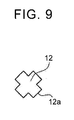
FIG. 9] FIG. 9 is a top view of a mandrel in the forging device of the modification illustrated inFIG. 8 . - [
FIG. 10] FIG. 10 is a sectional view illustrating a schematic configuration of a forging device of a modification. - [
FIG. 11] FIG. 11 is a sectional view illustrating a schematic configuration of a forging device of a modification. - The following describes an embodiment of the present invention in detail with reference to the drawings.
- Initially described is a configuration of a forging
device 1. Here,FIGS. 1 and2 are each a sectional view illustrating a schematic configuration of the forgingdevice 1 of the present embodiment.FIG. 1 illustrates a state before forging is performed on a workpiece W, andFIG. 2 illustrates a state after the forging is performed on the workpiece W. As illustrated inFIGS. 1 ,2 , the forgingdevice 1 includes a rotating table 10, amandrel 12, a shapingroller 14, roller moving means (not shown), and so on. - The rotating table 10 rotates around a rotation axis L1. Further, the rotating table 10 rotates the workpiece W placed on a
surface 10a, around a central axis of the workpiece W. - The
mandrel 12 is formed in a cylindrical shape. Themandrel 12 is placed on thesurface 10a of the rotating table 10 so that a central axis of themandrel 12 accords with the rotation axis L1 of the rotating table 10. When the workpiece W is placed on thesurface 10a of the rotating table 10, themandrel 12 is inserted inside an inner peripheral surface Wa of the workpiece W, and the workpiece W is placed on thesurface 10a of the rotating table 10 with an outerperipheral surface 12a of themandrel 12 making contact with the inner peripheral surface Wa of the workpiece W. This allows the central axis of the workpiece W to accord with the rotation axis L1 and the central axis of themandrel 12. - The shaping
roller 14 is formed in a cylindrical shape. Further, the shapingroller 14 includes an outerperipheral surface 14a, aninner end surface 14b, and so on. Here, theinner end surface 14b is an end surface on a rotation-axis-L1 side in a central-axis-L2 direction of the shapingroller 14. - In an example illustrated in
FIG. 1 , two shapingrollers 14 are provided. The twoshaping rollers 14 are placed at respective positions whose phases are shifted by 180° to each other in a rotation direction of the rotating table 10. The twoshaping rollers 14 are integrated with each other by ashaft 20 in such a state where their central axes L2 accord with each other. Theshaft 20 is attached to ahousing 22 in a rotatable state. Because of this, the two shapingrollers 14 integrated with each other by theshaft 20 rotate integrally around the central axes L2 of the shapingrollers 14. - Further, as illustrated in
FIG. 1 , the shapingroller 14 is placed apart from the rotation axis L1. That is, a gap is provided between the rotation axis L1 and theinner end surface 14b of the shaping roller 14 (more specifically, an intersection of theinner end surface 14b with the central axis L2). A distance δ0 between the rotation axis L1 and theinner end surface 14b is larger than a radius r of themandrel 12, but smaller than a radius R0 of the workpiece W. - Further, the central axis L2 of the shaping
roller 14 is generally perpendicular to the rotation axis L1. More specifically, the central axis L2 intersects with the rotation axis L1 at an angle of 90° ± 10° (that is, 80° to 100°), for example. - Note that materials of the rotating table 10, the
mandrel 12, and the shapingroller 14 may be cold working tool steel (SKD11, SKH), cemented carbide, and the like, for example. Further, the outerperipheral surface 14a of the shapingroller 14 is a part that makes contact with the workpiece W, which will be described later. On this account, it is desirable that coating be performed on the outerperipheral surface 14a of the shapingroller 14 so as to maintain a surface state. - Further, the roller moving means is attached to the
housing 22. The roller moving means moves thehousing 22 in parallel along a rotation-axis-L1 direction of the rotating table 10, so as to move the two shapingrollers 14 in parallel to the rotation axis L1. Note that the roller moving means is a ball screw, a hydraulic mechanism, or the like, for example. - Further, the forging
device 1 includes a controlling portion (not shown). The controlling portion is constituted by a microcomputer, for example, and controls driving of the rotating table 10, the roller moving means, and so on. - Next will be described a forging method for forging the workpiece W by use of the forging
device 1, as an operation of the forgingdevice 1 having the above configuration. - In the present embodiment, first, the workpiece W having a hollow cylindrical shape is placed on the
surface 10a of the rotating table 10. At this time, themandrel 12 is inserted inside the inner peripheral surface Wa of the workpiece W so that the central axis of the workpiece W accords with the rotation axis L1 of the rotating table 10. Note that a height H (a length in the rotation-axis-L1 direction) of themandrel 12 is larger than a height h (a length in the rotation-axis-L1 direction) of the workpiece W. - Then, the rotating table 10 and the
mandrel 12 are rotated around the rotation axis L1 (the central axis of themandrel 12, the central axis of the workpiece W). Hereby, the workpiece W is rotated around the rotation axis L1. - Then, the shaping
roller 14 is moved toward the workpiece W by the roller moving means. Then, the outerperipheral surface 14a of the shapingroller 14 is pressed against an end surface Wb of the workpiece W (an end surface thereof at a shaping-roller-14 side in the central-axis direction of the workpiece W), so that the shapingroller 14 makes contact with the workpiece W. Here, as described above, the workpiece W is being rotated around the rotation axis L1. Because of this, when the shapingroller 14 makes contact with the workpiece W as described above, the shapingroller 14 rotates following the workpiece W. That is, the shapingroller 14 rotates around the central axis L2. - Further, the shaping
roller 14 is moved toward the workpiece W by the roller moving means. This causes a pressure to be applied to the end surface Wb of the workpiece W from the shapingroller 14, so that the workpiece W expands outwardly in a radial direction of the workpiece W. Hereby, diameter expansion molding is performed on the workpiece W. - Further, in the present embodiment, the distance δ0 between the rotation axis L1 of the rotating table 10 (the central axis of the workpiece W) and the
inner end surface 14b of the shapingroller 14 is larger than the radius r of themandrel 12, but smaller than the radius R0 (seeFIG. 1 ) of the workpiece W before the workpiece W is forged and a radius R1 (seeFIG. 2 ) of the workpiece W after the workpiece W is forged. Hereby, at the time when the workpiece W is forged and after the workpiece W is forged, the shapingroller 14 is separated from themandrel 12, as illustrated inFIG. 2 . More specifically, the outerperipheral surface 12a of themandrel 12 is separated from theinner end surface 14b of the shapingroller 14 by a distance δ1, so that a gap is provided between the outerperipheral surface 12a of themandrel 12 and theinner end surface 14b of the shapingroller 14. Because of this, when a pressure is applied to the end surface Wb of the workpiece W from the shapingroller 14 as described above, a radially inner part of the workpiece W is raised toward a shaping-roller-14 side in the rotation-axis-L1 direction, as illustrated inFIG. 2 . Hereby, a boss portion Wc raised in the central-axis direction of the workpiece W is formed at a central part of the workpiece W. Thus, boss molding is performed on the workpiece W. - Here, the following more specifically describes how the diameter expansion molding and the boss molding are performed on the workpiece W. At the time when the workpiece W is forged, the shaping
roller 14 revolves around the rotation axis L1 of the rotating table 10 as illustrated inFIG. 3 , when viewed from the workpiece W. At this time, due to movement of an intersection between the workpiece W and the shapingroller 14, a material of the workpiece W flows toward an outer-peripheral-surface-Wd side of the workpiece W so that the material is scraped off, as illustrated inFIG. 4 , and also flows toward a rotation-axis-L1 side (a mandrel-12 side). When the material of the workpiece W flows toward the outer-peripheral-surface-Wd side of the workpiece W, the diameter expansion molding to expand the workpiece W in the radial direction of the workpiece W is performed. Further, when the material of the workpiece W flows toward the rotation-axis-L1 side (the mandrel-12 side), the material of the workpiece W flows to the central-axis direction of the workpiece W along the outerperipheral surface 12a of themandrel 12. Hereby, the boss molding to form the boss portion Wc is performed. - As described above, in the present embodiment, it is possible to perform the diameter expansion molding and the boss molding on the workpiece W at the same time.
- Here, in a conventional technique (e.g., Japanese Patent Application Publication No.
61-144232 JP 61-144232 A outer end 104 on ashaping surface 102 of a shapingroller 100 is placed at an inner side in a radial direction of the workpiece W relative to a position of an outer periphery WOb of the workpiece W0, as illustrated inFIG. 5 . This causes such a state that the shapingsurface 102 of the shapingroller 100 is pressed against only part of an end surface W0a of the workpiece W0 in the radial direction of the workpiece W0, so that accuracy of the end surface W0a of the workpiece W0 that has been forged might decrease. - In contrast, in the forging
device 1 of the present embodiment, a position of thatouter end 14c of the outerperipheral surface 14a of the shapingroller 14 which is opposite to the rotation-axis-L1 side in the central-axis-L2 direction is placed at an outer side in the radial direction of the workpiece W relative to a position of the outer peripheral surface Wd of the workpiece W that has been forged, as illustrated inFIG. 2 . This causes such a state where the outerperipheral surface 14a of the shapingroller 14 is pressed against a large area of the end surface Wb of the workpiece W in the radial direction of the workpiece W, from the beginning of the forging of the workpiece W to the end of the forging. This makes it possible to secure accuracy of the end surface Wb of the workpiece W that has been forged, by the outerperipheral surface 14a of the shapingroller 14. This accordingly improves accuracy of the end surface Wb of the workpiece W that has been forged. - Further, in comparison with conventional die forging (forging using a molding die), the forging
device 1 can perform the diameter expansion molding and the boss molding at a low load. - Further, in the present embodiment, since the material of the workpiece W flows while making close contact with the
mandrel 12 from the beginning of molding, accuracy of an inside diameter of the workpiece W that has been forged can be easily secured. - Note that such an example in which only one shaping
roller 14 is provided can be considered as a modification. - Further, as another modification, such an example in which a
mandrel 12 is provided separately from a rotating table 10 can be considered, as illustrated inFIG. 6 . Further, as illustrated inFIG. 7 , such an example in which asurface 10a of a rotating table 10 is formed as an inclined surface, and an outerperipheral surface 14a of a shapingroller 14 is formed to be inclined relative to a central axis L2 can be also considered. Further, as illustrated inFIGS. 8 ,9 , splines may be formed on an outerperipheral surface 12a of amandrel 12. This makes it possible to form a boss portion Wc while forming splines on an inner peripheral surface Wa of a workpiece W. Further, as illustrated inFIG. 10 , such an example in which asurface 10a of a rotating table 10 is formed to have a waveform shape. - Further, as another modification, a forging device that does not include a
mandrel 12 can be considered, as illustrated inFIG. 11 . At this time, a workpiece W that has not been forged yet is formed in a solid cylindrical shape. Note thatFIGS. 6 to 8 ,10 , and11 partially illustrate a forging device. - Further, as a modification, such an example in which a central axis L2 of a shaping
roller 14 intersects with a rotation axis L1 of a rotating table 10 at an angle of 45° to 90° can be considered. - In the present embodiment, in the forging
device 1 which includes the rotating table 10 that rotates around the rotation axis L1, and thecylindrical shaping roller 14, and which forges the cylindrical workpiece W such that the outerperipheral surface 14a of the shapingroller 14 is pressed against the end surface Wb of the workpiece W in the central-axis direction of the workpiece W while the workpiece W is rotated by the rotating table 10 around the central axis of the workpiece W, the shapingroller 14 is placed apart from the rotation axis L1, and the position of thatouter end 14c of the outerperipheral surface 14a of the shapingroller 14 which is opposite to the rotation-axis-L1 side in the central-axis-L2 direction of the shapingroller 14 is placed at the outer side in the radial direction of the workpiece W relative to the position of the outer peripheral surface Wd of the workpiece W that has been forged. - As such, the diameter expansion molding to expand the cylindrical workpiece W in the radial direction can be performed such that the outer
peripheral surface 14a of the shapingroller 14 is pressed against the end surface Wb of the workpiece W in the central-axis-L2 direction of the workpiece W while the workpiece W is rotated by the rotating table 10 around the central axis of the workpiece W. Further, since the shapingroller 14 is placed apart from the rotation axis L1 of the rotating table 10, the material of the workpiece W flows toward the rotation-axis-L1 side relative to the shapingroller 14, so that the boss molding to form the boss portion Wc formed by raising a central part of the workpiece W in the central-axis direction of the workpiece W can be performed. Thus, the diameter expansion molding and the boss molding can be performed at the same time. This makes it possible to manufacture a forging having the boss portion Wc while achieving reduction in cost. - Further, the position of that
outer end 14c of the outerperipheral surface 14a of the shapingroller 14 which is opposite to the rotation-axis-L1 side of the rotating table 10 in the central-axis-L2 direction of the shapingroller 14 is placed at the outer side in the radial direction of the workpiece W relative to the position of the outer peripheral surface Wd of the workpiece W that has been forged. This causes such a state where the outerperipheral surface 14a of the shapingroller 14 is pressed against a large area of the end surface Wb of the workpiece W, in the central-axis direction of the workpiece W, during the forging of the workpiece W. This makes it possible to secure accuracy of the end surface Wb of the workpiece W that has been forged, by the outerperipheral surface 14a of the shapingroller 14. This can accordingly improve the accuracy of the end surface Wb of the workpiece W that has been forged. - Further, it is preferable that: the forging
device 1 include thecylindrical mandrel 12; the central axis of themandrel 12 accord with the rotation axis L1 of the rotating table 10; the shapingroller 14 have theinner end surface 14b placed at the rotation-axis-L1 side in the central-axis-L2 direction of the shapingroller 14; and the distance δ1 between the central axis of themandrel 12 and theinner end surface 14b be larger than the radius of themandrel 12, but smaller than the radius of the workpiece. - Hereby, by flowing the material of the workpiece W between the outer
peripheral surface 12a of themandrel 12 and theinner end surface 14b of the shapingroller 14, it is possible to form the boss portion Wc having a hollow cylindrical shape in the central part of the workpiece W. Since the material of the workpiece W flows while making close contact with the outerperipheral surface 12a of themandrel 12, it is possible to secure desired accuracy on an inner peripheral surface of the boss portion Wc by managing accuracy of the outerperipheral surface 12a of themandrel 12. - Further, when the forging
device 1 includes two shapingrollers 14, it is possible to shorten a time to forge the workpiece W. Also, the accuracy of the end surface Wb of the workpiece W is improved. - Further, in the forging
device 1, the central axis L2 of the shapingroller 14 is generally perpendicular to the rotation axis L1 of the rotating table 10. This makes it possible to simplify a mechanism for supporting the shapingroller 14. Particularly, in a case where two shapingrollers 14 are provided, the two shapingrollers 14 can be integrated with each other by oneshaft 20 while central axes of the two shapingrollers 14 accord with each other. This accordingly makes it possible to simplify the mechanism for supporting the two shapingrollers 14. Accordingly, the two shapingrollers 14 can be easily handled. Further, a force that can be added to the workpiece W from the shapingrollers 14 can be increased. Also, rigidity of the shapingrollers 14 can be obtained. - Note that the above embodiment is merely an example, and does not limit the present invention at all. It goes without saying that the present invention can be altered or modified variously within a range which does not deviate from the gist of the present invention.
- A forging manufactured by the forging
device 1 and the forging method of the present invention is suitable for a power transmission component. For example, the forging is most suitable for steel components used for power transmission, such as a gear wheel and a shaft used in an automobile, a construction vehicle, a construction machine, and the like, and particularly, a transmission gear wheel of an automobile and a sheave of CVT. -
- 1
- forging device
- 10
- rotating table
- 10a
- surface
- 12
- mandrel
- 12a
- outer peripheral surface
- 14
- shaping roller
- 14a
- outer peripheral surface
- 14b
- inner end surface
- 14c
- outer end
- 20
- shaft
- 22
- housing
- L1
- rotation axis
- L2
- central axis
- W
- workpiece
- Wa
- inner peripheral surface
- Wb
- end surface
- Wc
- boss portion
- Wd
- outer peripheral surface
- H
- height (of mandrel)
- h
- height (of workpiece)
- r
- radius (of mandrel)
- R0
- radius (of workpiece that has not been forged)
- R1
- radius (of workpiece that has been forged)
- δ0
- distance
- δ1
- distance
Claims (8)
- A forging device including a rotating table that rotates around a rotation axis, and a cylindrical shaping roller, the forging device forging a cylindrical workpiece such that an outer peripheral surface of the shaping roller is pressed against an end surface of the workpiece in a central-axis direction of the workpiece while the workpiece is rotated by the rotating table around a central axis of the workpiece, the forging device being characterized in that:the shaping roller is placed apart from the rotation axis; anda position of that end of the outer peripheral surface of the shaping roller which is opposite to a rotation-axis side in a central-axis direction of the shaping roller is placed at an outer side in a radial direction of the workpiece relative to a position of an outer peripheral surface of the workpiece that has been forged.
- The forging device according to claim 1, characterized by comprising:a cylindrical mandrel, wherein:a central axis of the mandrel accords with the rotation axis;the shaping roller has an inner end surface placed at the rotation-axis side in the central-axis direction of the shaping roller; anda distance between the central axis of the mandrel and the inner end surface is larger than a radius of the mandrel but smaller than a radius of the workpiece.
- The forging device according to claim 1 or 2, characterized by comprising:two shaping rollers.
- The forging device according to any one of claims 1 to 3, characterized in that:a central axis of the shaping roller is generally perpendicular to the rotation axis.
- A forging method for forging a cylindrical workpiece, by use of a rotating table that rotates around a rotation axis, and a cylindrical shaping roller, such that an outer peripheral surface of the shaping roller is pressed against an end surface of the workpiece in a central-axis direction of the workpiece while the workpiece is rotated by the rotating table around a central axis of the workpiece, the forging method being characterized in that:the shaping roller is placed apart from the rotation axis; anda position of that end of the outer peripheral surface of the shaping roller which is opposite to a rotation-axis side in a central-axis direction of the shaping roller is placed at an outer side in a radial direction of the workpiece relative to a position of an outer peripheral surface of the workpiece that has been forged.
- The forging method according to claim 5, characterized in that:a cylindrical mandrel is used;a central axis of the mandrel accords with the rotation axis;the shaping roller has an inner end surface placed at the rotation-axis side in the central-axis direction of the shaping roller; anda distance between the central axis of the mandrel and the inner end surface is larger than a radius of the mandrel but smaller than a radius of the workpiece.
- The forging method according to claim 5 or 6, characterized in that:two shaping rollers are used.
- The forging method according to any one of claims 5 to 7, characterized in that:a central axis of the shaping roller is generally perpendicular to the rotation axis.
Applications Claiming Priority (2)
| Application Number | Priority Date | Filing Date | Title |
|---|---|---|---|
| JP2013015916A JP2014144481A (en) | 2013-01-30 | 2013-01-30 | Forging apparatus and forging method |
| PCT/JP2013/082464 WO2014119120A1 (en) | 2013-01-30 | 2013-12-03 | Forging device and forging method |
Publications (2)
| Publication Number | Publication Date |
|---|---|
| EP2952273A1 true EP2952273A1 (en) | 2015-12-09 |
| EP2952273A4 EP2952273A4 (en) | 2016-03-23 |
Family
ID=51261850
Family Applications (1)
| Application Number | Title | Priority Date | Filing Date |
|---|---|---|---|
| EP13873655.8A Withdrawn EP2952273A4 (en) | 2013-01-30 | 2013-12-03 | FORGING DEVICE AND FORGING METHOD |
Country Status (8)
| Country | Link |
|---|---|
| US (1) | US20150352629A1 (en) |
| EP (1) | EP2952273A4 (en) |
| JP (1) | JP2014144481A (en) |
| KR (1) | KR20150103187A (en) |
| CN (1) | CN104968450A (en) |
| BR (1) | BR112015018258A2 (en) |
| RU (1) | RU2015131210A (en) |
| WO (1) | WO2014119120A1 (en) |
Cited By (1)
| Publication number | Priority date | Publication date | Assignee | Title |
|---|---|---|---|---|
| FR3083463A1 (en) | 2018-07-03 | 2020-01-10 | Tusas Motor Sanayii Anonim Sirketi | Rotational symmetrical and non-symmetrical plastic forming machine |
Families Citing this family (1)
| Publication number | Priority date | Publication date | Assignee | Title |
|---|---|---|---|---|
| CN106903255A (en) * | 2017-04-19 | 2017-06-30 | 中国航发北京航空材料研究院 | A kind of rotary rolling forging apparatus of Rotary forging |
Family Cites Families (12)
| Publication number | Priority date | Publication date | Assignee | Title |
|---|---|---|---|---|
| DE2901083C2 (en) * | 1979-01-12 | 1983-05-11 | Siemens AG, 1000 Berlin und 8000 München | Smoothing device for perforated metal disks |
| JPS61144232A (en) | 1984-12-17 | 1986-07-01 | Nabeya Kogyo Kk | Manufacture of pulley |
| US5951422A (en) * | 1996-06-24 | 1999-09-14 | The Gates Corporation | Hub and pulley with radially inward annular collar |
| JP2000051987A (en) * | 1998-08-05 | 2000-02-22 | Daido Steel Co Ltd | Hot forging method |
| DE19960582A1 (en) * | 1999-12-15 | 2000-08-03 | Leico Werkzeugmaschb Gmbh & Co | Pressure rolling process for transmission components, involving clamping workpiece to tool, rotating it, partly separating sector with pressure roller and deforming |
| JP3812329B2 (en) * | 2000-03-14 | 2006-08-23 | 日産自動車株式会社 | Plastic working method |
| JP2004098089A (en) * | 2002-09-05 | 2004-04-02 | Mitsubishi Heavy Ind Ltd | Method and device for forming disk-shaped component |
| JP5056719B2 (en) * | 2008-10-17 | 2012-10-24 | トヨタ自動車株式会社 | Sequential molding apparatus and method |
| JP2010099729A (en) * | 2008-10-27 | 2010-05-06 | Toyota Motor Corp | Sequential forming apparatus and its method |
| CN101722260B (en) * | 2009-12-10 | 2011-04-27 | 中冶陕压重工设备有限公司 | Free forging method of forge piece of rotary arms |
| JP2011224581A (en) * | 2010-04-15 | 2011-11-10 | Toyota Motor Corp | Roller forging method |
| JP2011224605A (en) | 2010-04-19 | 2011-11-10 | Toyota Motor Corp | Forging method |
-
2013
- 2013-01-30 JP JP2013015916A patent/JP2014144481A/en active Pending
- 2013-12-03 RU RU2015131210A patent/RU2015131210A/en unknown
- 2013-12-03 EP EP13873655.8A patent/EP2952273A4/en not_active Withdrawn
- 2013-12-03 US US14/764,699 patent/US20150352629A1/en not_active Abandoned
- 2013-12-03 BR BR112015018258A patent/BR112015018258A2/en not_active IP Right Cessation
- 2013-12-03 CN CN201380071753.5A patent/CN104968450A/en active Pending
- 2013-12-03 KR KR1020157020584A patent/KR20150103187A/en not_active Withdrawn
- 2013-12-03 WO PCT/JP2013/082464 patent/WO2014119120A1/en not_active Ceased
Cited By (2)
| Publication number | Priority date | Publication date | Assignee | Title |
|---|---|---|---|---|
| FR3083463A1 (en) | 2018-07-03 | 2020-01-10 | Tusas Motor Sanayii Anonim Sirketi | Rotational symmetrical and non-symmetrical plastic forming machine |
| US11684967B2 (en) | 2018-07-03 | 2023-06-27 | Tusas Motor Sanayii Anonim Sirketi | Rotational symmetrical and non-symmetrical plastic forming machine |
Also Published As
| Publication number | Publication date |
|---|---|
| JP2014144481A (en) | 2014-08-14 |
| EP2952273A4 (en) | 2016-03-23 |
| WO2014119120A1 (en) | 2014-08-07 |
| KR20150103187A (en) | 2015-09-09 |
| CN104968450A (en) | 2015-10-07 |
| US20150352629A1 (en) | 2015-12-10 |
| RU2015131210A (en) | 2017-03-03 |
| BR112015018258A2 (en) | 2017-07-18 |
Similar Documents
| Publication | Publication Date | Title |
|---|---|---|
| EP3194093B1 (en) | Method of manufacturing a hollow rack bar | |
| JP6237100B2 (en) | Manufacturing method of wheel bearing rolling bearing unit | |
| EP2690262A1 (en) | Method for manufacturing hollow engine valve | |
| JP2002172430A (en) | Method and apparatus for manufacturing cylindrical member and cylindrical member having spline | |
| JPWO2018179928A1 (en) | Steering device shaft, manufacturing method of steering device shaft, and electric power steering device | |
| US11077875B2 (en) | Rack and a method for producing a rack for a steering gear of a motor vehicle | |
| EP2952273A1 (en) | Forging device and forging method | |
| JP6641903B2 (en) | Method for manufacturing ring-shaped member | |
| JP7216934B2 (en) | Bearing elements, bearings, machines and vehicles | |
| EP2842649B1 (en) | A method of rolling extrusion with regulated axis spacing of axi-symmetrical stepped parts | |
| JP5012038B2 (en) | Metal ring manufacturing method | |
| JP6402847B1 (en) | Mold apparatus for manufacturing cylindrical rolling element, manufacturing method of cylindrical rolling element, manufacturing method of rolling bearing, manufacturing method of vehicle, and manufacturing method of mechanical device | |
| JP4826491B2 (en) | Method for manufacturing bearing ring member | |
| JP4840238B2 (en) | Manufacturing method of flanged member and work member used therefor | |
| JP5134361B2 (en) | 2-stage helical gear | |
| JP6458854B2 (en) | Manufacturing apparatus and manufacturing method for ring-shaped member, manufacturing method and manufacturing apparatus for radial rolling bearing, and manufacturing method for rotating device | |
| JP2016159337A (en) | Rotary forging method, rotary forging die and rotary forged parts | |
| JP6750513B2 (en) | Hub and manufacturing method thereof | |
| EP3903962A1 (en) | Linear motion shaft for steering device, steering device, and method of manufacturing these | |
| JP5625550B2 (en) | Manufacturing apparatus and manufacturing method of flanged hollow shaft member | |
| JP6245112B2 (en) | Manufacturing method and manufacturing apparatus for ring-shaped member, manufacturing method and manufacturing apparatus for radial rolling bearing, and manufacturing method for rotating device | |
| JP6287792B2 (en) | Manufacturing method and manufacturing apparatus for ring-shaped member, manufacturing method and manufacturing apparatus for radial rolling bearing, and manufacturing method for rotating device | |
| JP2007111740A (en) | Screw shaft forming method and screw shaft of ball screw mechanism | |
| JP2018027572A (en) | Ring-shaped member manufacturing apparatus | |
| JP6340293B2 (en) | Manufacturing method for hollow products |
Legal Events
| Date | Code | Title | Description |
|---|---|---|---|
| PUAI | Public reference made under article 153(3) epc to a published international application that has entered the european phase |
Free format text: ORIGINAL CODE: 0009012 |
|
| 17P | Request for examination filed |
Effective date: 20150729 |
|
| AK | Designated contracting states |
Kind code of ref document: A1 Designated state(s): AL AT BE BG CH CY CZ DE DK EE ES FI FR GB GR HR HU IE IS IT LI LT LU LV MC MK MT NL NO PL PT RO RS SE SI SK SM TR |
|
| AX | Request for extension of the european patent |
Extension state: BA ME |
|
| A4 | Supplementary search report drawn up and despatched |
Effective date: 20160219 |
|
| RIC1 | Information provided on ipc code assigned before grant |
Ipc: B21K 21/06 20060101ALI20160215BHEP Ipc: B21H 1/18 20060101AFI20160215BHEP Ipc: B21J 5/08 20060101ALI20160215BHEP Ipc: B21D 22/16 20060101ALI20160215BHEP Ipc: B21K 23/04 20060101ALI20160215BHEP Ipc: B21K 21/16 20060101ALI20160215BHEP Ipc: B21D 53/26 20060101ALI20160215BHEP Ipc: B21J 5/06 20060101ALI20160215BHEP |
|
| DAX | Request for extension of the european patent (deleted) | ||
| STAA | Information on the status of an ep patent application or granted ep patent |
Free format text: STATUS: THE APPLICATION IS DEEMED TO BE WITHDRAWN |
|
| 18D | Application deemed to be withdrawn |
Effective date: 20160920 |