EP2951959B1 - Utilisation d'une commutation de protection d'anneau ethernet avec des réseaux d'ordinateurs - Google Patents
Utilisation d'une commutation de protection d'anneau ethernet avec des réseaux d'ordinateurs Download PDFInfo
- Publication number
- EP2951959B1 EP2951959B1 EP14704486.1A EP14704486A EP2951959B1 EP 2951959 B1 EP2951959 B1 EP 2951959B1 EP 14704486 A EP14704486 A EP 14704486A EP 2951959 B1 EP2951959 B1 EP 2951959B1
- Authority
- EP
- European Patent Office
- Prior art keywords
- routing device
- homed
- remote
- connectivity
- core network
- Prior art date
- Legal status (The legal status is an assumption and is not a legal conclusion. Google has not performed a legal analysis and makes no representation as to the accuracy of the status listed.)
- Not-in-force
Links
Images

Classifications
-
- H—ELECTRICITY
- H04—ELECTRIC COMMUNICATION TECHNIQUE
- H04L—TRANSMISSION OF DIGITAL INFORMATION, e.g. TELEGRAPHIC COMMUNICATION
- H04L12/00—Data switching networks
- H04L12/28—Data switching networks characterised by path configuration, e.g. LAN [Local Area Networks] or WAN [Wide Area Networks]
- H04L12/42—Loop networks
- H04L12/437—Ring fault isolation or reconfiguration
-
- H—ELECTRICITY
- H04—ELECTRIC COMMUNICATION TECHNIQUE
- H04L—TRANSMISSION OF DIGITAL INFORMATION, e.g. TELEGRAPHIC COMMUNICATION
- H04L12/00—Data switching networks
- H04L12/28—Data switching networks characterised by path configuration, e.g. LAN [Local Area Networks] or WAN [Wide Area Networks]
- H04L12/46—Interconnection of networks
- H04L12/4641—Virtual LANs, VLANs, e.g. virtual private networks [VPN]
-
- H—ELECTRICITY
- H04—ELECTRIC COMMUNICATION TECHNIQUE
- H04L—TRANSMISSION OF DIGITAL INFORMATION, e.g. TELEGRAPHIC COMMUNICATION
- H04L41/00—Arrangements for maintenance, administration or management of data switching networks, e.g. of packet switching networks
- H04L41/06—Management of faults, events, alarms or notifications
- H04L41/0654—Management of faults, events, alarms or notifications using network fault recovery
-
- H—ELECTRICITY
- H04—ELECTRIC COMMUNICATION TECHNIQUE
- H04L—TRANSMISSION OF DIGITAL INFORMATION, e.g. TELEGRAPHIC COMMUNICATION
- H04L45/00—Routing or path finding of packets in data switching networks
- H04L45/28—Routing or path finding of packets in data switching networks using route fault recovery
-
- H—ELECTRICITY
- H04—ELECTRIC COMMUNICATION TECHNIQUE
- H04L—TRANSMISSION OF DIGITAL INFORMATION, e.g. TELEGRAPHIC COMMUNICATION
- H04L45/00—Routing or path finding of packets in data switching networks
- H04L45/66—Layer 2 routing, e.g. in Ethernet based MAN's
Definitions
- the present disclosure relates generally to computer networks, and, more particularly, to using Ethernet ring protection switching with computer networks.
- L2VPN Layer 2 Virtual Private Network
- One solution to avoid looping conditions is to apply a spanning tree protocol.
- the spanning tree protocol has problems with scalability, and can also result in looping conditions if the spanning tree protocol is misconfigured. Additionally, the spanning tree protocol is typically run "over the top" of a service provider's network and thus the service provider has no control or visibility that the solution is enabled and working properly.
- US 2012/219004 discloses a generalized multi-homing capability using a generalized multi-homed site object and associated generalized multi-homed site identifier for Virtual Private LAN Services (VPLS).
- the generalized multi-homed site object is configured to support multiple types of endpoints, thereby enabling multi-homing to be supported for various types of devices in various types of networks.
- a first routing device establishes a virtual channel with a remote routing device in a G.8032 protocol Ethernet network ring.
- the first routing device and the remote routing device each being linked to a multi-homed routing device having Layer 2 connectivity to a core network.
- the multi-homed routing device is not configured with the G.8032 protocol.
- the first routing device identifies a link state from the first routing device to the multi-homed routing device. Layer 2 connectivity of the first routing device to the core network is controlled based upon the identified link state of the first routing device.
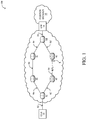
- an Ethernet ring 2 is an Ethernet network comprising nodes 4 and links 6 connected together in a closed loop topology.
- One of the links 6 of the ring is typically designated as a Ring Protection Link (RPL), and is disabled during normal operation of the ring by placing a channel block on that link.
- RPL Ring Protection Link
- a channel block 8 is imposed at a node at one end of the RPL, which node may then be referred to as the RPL Owner.
- the channel block 8 may, for example, comprise a policy that prevents packets of the ring from being forwarded through a port hosting the RPL. With such a channel block in place, the ring 2 is guaranteed to be loop free, and conventional Ethernet MAC-learning and path computation can be used to compute and install appropriate forwarding information in each node of the ring.
- a failure of either a link 6 or a node 4 of the ring 2 will be detected by the two nodes 4 nearest the point of failure. Both of these nodes will send a signal fail message to their nearest neighbor nodes in the ring, and these FIMs will be propagated, in opposite directions, around the ring.
- each node flushes its forwarding database (FDB), and forwards the FIM to the next node on the ring.
- FDB forwarding database
- the RPL-Owner will remove the channel block 8. This effectively enables connectivity within the ring to be re-established using conventional Ethernet flooding and MAC learning functionality.
- ITU-T recommendation G.8032 utilizes conventional Ethernet path labeling and packet forwarding techniques to implement a ring network.
- ITU-T recommendation G.8032 contemplates an arrangement in which the ring network is defined entirely within a given Ethernet network domain.
- customer located equipment such as a customer premised Local Area Network or router, for example
- CLE customer located equipment
- the Ethernet ring 2 can connect to a network edge node such as a gateway (GW) 14 to a foreign network domain 16 through a hand-off connection 18.
- GW gateway
- a method for implementing the access connection 12 between the CLE 10 and the Ethernet ring 2 are discussed with reference to the illustrated embodiment of FIG. 2 .
- Such a solution should at least meet the requirements: 1) guarantees 50ms convergence time for access failure; 2) handles link, port, PE node failures and PE node isolation from an MPLS core; 3) supports E-LINE, E-LAN and E-TREE services; supports active/standby (1:1) as well as active/active (1+1) redundancy modes; 4) requires minimal resiliency control protocol support on a multi-homed device (CE) (e.g., no MST or G.8032 support on CE; and 5) supports co-located and geo-redundant PE's.
- CE multi-homed device
- ITU-T G.8032 is a standards based Ethernet ring protection switching recommendation to provide sub-50ms protection and recovery switching for Ethernet traffic in a ring topology while at the same time ensuring that there are no loops formed at the Ethernet layer.
- a redundancy solution for device multi-homing using G.8032 is provided having the desired aforesaid active/standby (1:1) and active/active (1+1) PE redundancy.
- FIG. 2 depicts a diagram of an example of a computer network system 100, in accordance with an illustrative embodiment, utilizing Ethernet Ring Protection Switching.
- the network system 100 includes a dual-homed routing device (DHD) 102, which is a type of a multi-homed routing device, linked with routing devices 104 and 106.
- DHD dual-homed routing device
- multi-homing is a network topology in which a network device is connected to the network by way of two or more independent access points (or points of attachment). Therefore, a dual-homed device, such as dual-homed routing device 102, is a network device (e.g., customer located equipment 10) connected to a network by way of two independent access points.
- a triple-homed device for instance is a network device connected to a network by way of three independent access points.
- the PE devices 104 and 106 are physically separate elements providing redundant access to routing device 102, along with physical separate attachment circuits, which are connected to the communication links 150 and 151, terminating on the routing devices 104 and 106, respectively.
- the routing devices 104 and 106 are in communication with each other by way of a virtual channel 108 and are grouped as a single redundancy group, which refers to groupings of network devices (e.g., routing devices 104 and 106) for providing access protection to multi-homed devices.
- a virtual channel refers to a control channel 108 for communication between routing devices within a redundancy group (e.g., routing devices 104 and 106) and as preferably defined in the G.8032 standard.
- the link states for links 150 or 151 may also be referred to as an "attachment circuit state," and such terms may be used interchangeably.
- an "attachment circuit” is a physical or virtual circuit attaching, for example, a multi-homed routing device 102 to a remote routing device 104 or 106.
- An attachment circuit can be, for example, an Ethernet port or a Virtual Local Area Network (VLAN) on the Ethernet port.
- VLAN Virtual Local Area Network
- PW pseudowires 182
- a "pseudowire” (e.g., one of many pseudowires 182) is an emulation of a service over a packet-switching network (e.g., MPLS or Internet Protocol),
- the emulated service may be ATM, Frame Relay, Ethernet, low-rate Time-division multiplexing (TDM), or Synchronous optical networking (SONET).
- TDM Time-division multiplexing
- SONET Synchronous optical networking
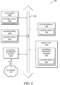
- FIG. 3 shown is a simplified block diagram of a machine in the example form of an apparatus 200 within which a set of instructions, for causing the machine (e.g., an "attachment circuits) to perform any one or more of the methodologies discussed herein, may be executed and utilized within the components illustrated in the embodiment of FIG. 2 .
- the machine may be connected (e.g., networked) to other machines.
- the machine is capable of executing a set of instructions (sequential or otherwise) that specify actions to be taken by that machine.
- the term "machine” shall also be taken to include any collection of machines that individually or jointly execute a set (or multiple sets) of instructions to perform any one or more of the methodologies discussed herein.
- the example apparatus 200 includes a processor 1002 (e.g., a central processing unit (CPU)), a main memory 1004, and a static memory 1006, which communicate with each other via bus 1008.
- the apparatus 200 may also include a secondary memory component 1016 (e.g., a disk drive unit, flash, etc.) and a network interface device 1020.
- the secondary memory component 1016 includes machine-readable medium 1022 on which is stored one or more sets of instructions and data structures 1024 (e.g., software) embodying or utilized by any one or more of the methodologies or functions described herein.
- the instructions may also reside, completely or at least partially, within the main memory 1004 and/or within the processor 1002 during execution thereof by the apparatus 200, with the main memory 1004 and the processor 1002 also constituting machine-readable, tangible media.
- the instructions 1024 may further be transmitted or received over computer network 1026 via network interface device 1020 utilizing any one of a number of well-known transfer protocols.
- machine-readable medium 1022 is shown in an embodiment to be a single medium, the term “machine-readable medium” should be taken to include a single medium or multiple media (e.g., a centralized or distributed database, and/or associated caches) that store the one or more sets of instructions.
- the term “machine-readable medium” shall also be taken to include any medium that is capable of storing, encoding or carrying a set of instructions for execution by the machine and that cause the machine to perform any one or more of the methodologies of the present application, or that is capable of storing, encoding or carrying data structures utilized by or associated with such a set of instructions.
- the term “machine-readable midium” shall accordingly be taken to include, but not be limited to, solid-state memories, optical and magnetic media, etc.
- PE devices 104 and 106 are shown coupled to an MPLS core network and are configured to provide Virtual Private Wire Service (VPWS) connectivity to the DHD device 102.
- VPWS Virtual Private Wire Service
- DHD device 102 is preferably provided with Layer 2 connectivity to the core network.
- the illustrated embodiment of FIG. 2 is not to be understood to be limited to VPWS connectivity.
- PE devices 104 and 106 preferably form a G.8032 open Ethernet ring with a ring automatic protection switching (R-APS) virtual channel (VCL) 108 coupling PE devices 104 and 106.
- R-APS ring automatic protection switching
- Ports 120 and 122 of respective PE devices 104 and 106 thus form the ring ports of the G.8032 open Ethernet ring wherein ports 124 and 126 of PE devices 104 and 106 complete the R-APS VLAN via VCL 108. It is to be appreciated that while the embodiment of Fig. 2 uses ports 124 and 126 to complete the R-APS VLAN, an Ethernet over MPLS pseudowire may alternatively be used (e.g., for geo-redundant PE devices).
- DHD device 102 is provided with ports 128 and 130 which are each preferably configured to have the same VLAN/Bridge domains used for forwarding customer data to PE devices 104 and 106. It is noted that in the embodiment of FIG. 2 , G.8032 is not configured on the DHD device 102 but a VLAN/Bridge domain is dedicated to ports 128 and 130 on DHD device 102 configured for relying G.8032 R-APS frames between PE devices 104 and 106. In the embodiment of FIG. 2 , G.8032 is preferably implemented within control logic on each PE device 104 and 106 (via attachment circuits).
- Ethernet Ring Protection (ERP) instances in the aforesaid G.8032 Ethernet ring, data traffic is load-balanced on a per VLAN basis between PE devices 104 and 106.
- ERP Ethernet Ring Protection
- port 120 of PE device 104 is operational to forward data traffic on the VLAN's for which it is not an RPL owner wherein control logic configured on the PE devices controls the PW state of each PE node based on the G.8032 state machine.
- the control logic on PE device 106 sets the corresponding PW to "Standby" with the RPL link to port 122 being in a blocked condition.
- Connectivity Failure Management (CFM) Down MEPs can be configured in the control logic on the PE and the DHD devices (102, 104 and 106) for faster failure detection whereby with Connectivity Fault Management (CFM) Continuity Check Messages (CCMs) running at approximately 3.3 msec, it is possible to detect access link failure condition in approximately 10 msec.
- CFM Connectivity Fault Management
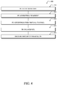
- the PE device e.g., 106
- the PE device e.g., 106
- the port e.g., 122 connecting to the failed link (e.g., 151)
- the failed PE device e.g., 106
- the PW state is set in Down state and Standby state is used when the attachment circuit (as per G8032 state machine) is blocked but has no active failure.
- the failed PE also advertises R-APS Signal Fail (SF) to the other PE device (104) over the virtual channel 108 (step 430).
- the other PE device e.g., 104
- data traffic can be reverted back to the original PE device (e.g., 106) by preferably G.8032 administrative Command Line Interface (CLI) or automatically after a G.8032 Wait To Restore (WTR) timer is expired (step 450).
- CFM Control Line Interface
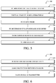
- each PE device monitors the status of the virtual channel 108 (step 510). As mentioned above, this again can be achieved using CFM CCMs.
- each PE device e.g., 104, 106 preferably starts a timer (configurable in msec) (step 530) to detect if a R-APS message is received from a remote PE device over the access link before the timer expires (step 540).
- the PE device deduces that the remote PE device (e.g., 106) has failed (step 550).
- the RPL is unblocked at its port (e.g., 120) and the updated PW status is advertised in LDP (step 560).
- the virtual channel may then be non-operational as a result of core-isolation on the remote PE.
- the latter will preferably trigger G.8032 protection switching and the local PE would receive R-APS from access link instantly. This way, the local PE can distinguish core isolation from remote PE node failure.
- backbone connectivity is monitored by each PE device (e.g., 104 and 106) using its control logic (step 610).
- Core isolation on a PE device (104, 106) preferably triggers G.8032 protection switching on its access port (120, 122) even though the core facing ports are not part of the G.8032 ring (step 620).
- the PE device (e.g., 106) then implements new logic which triggers the transmission of R-APS Signal Fail messages over its access link (e.g., 151), whenever the PE device (106) is isolated from the core network 100 (step 630).
- MAC address table flushing notification to the DHD (102), which preferably can be achieved by sending MVRP (Multiple VLAN Registration Protocol) messages to the DHD (102).
- MVRP Multiple VLAN Registration Protocol
- the access link (151) can be made non-operational so to cause MAC address table flushing on the DHD (102), which can be used to provide 1:1 redundancy.
- FIG. 2 provides a link redundancy protocol which provides a communication channel enabling redundant Ethernet access circuits to be terminated across multiple devices and thus, extending reliability beyond just link level protection but also to device level protection.
- this link redundancy protocol allows one of the communication links 150 or 151 to serve as a backup link by managing the links 150 and 151 in "active" and "standby" states (or modes) such that only one of the links 150 or 151 is active at a time.
- the communication link 151 actively passes network traffic while the communication link 150 is in a standby state.
Claims (15)
- Procédé comportant les étapes consistant à :établir, par un premier dispositif de routage (104), un canal virtuel (108) avec un dispositif de routage à distance (106) dans un anneau de réseau Ethernet de protocole G.8032, le premier dispositif de routage et le dispositif de routage à distance étant chacun reliés à un dispositif de routage à connexions multiples (102) ayant une connectivité de couche 2 à un réseau central (182) dans lequel le dispositif de routage à connexions multiples n'est pas configuré avec le protocole G.8032 ;identifier, dans le premier dispositif de routage, un état de liaison depuis le premier dispositif de routage jusqu'au dispositif de routage à connexions multiples ;surveiller la connectivité au réseau central ; etcommander la connectivité de couche 2 du dispositif de routage à connexions multiples au réseau central en fonction de l'état de liaison identifié du premier dispositif de routage et de la connectivité surveillée au réseau central.
- Procédé selon la revendication 1, dans lequel l'étape consistant à commander comporte, en réponse à la détermination comme quoi le premier dispositif de routage est isolé du réseau central, l'étape consistant à déclencher la commutation de protection G.8032 sur un port d'accès connecté au dispositif de routage à connexions multiples.
- Procédé selon la revendication 1, dans lequel le canal virtuel est une session de plan de commande entre châssis.
- Procédé selon la revendication 3, dans lequel la session de plan de commande entre châssis est un canal virtuel R-APS (ring automatique protection switching - commutation de protection automatique d'anneau).
- Procédé selon la revendication 1, dans lequel seul l'un parmi le premier dispositif de routage et le dispositif de routage à distance est configuré sous la forme d'une RPL (ring protection link - liaison de protection d'anneau).
- Procédé selon la revendication 5, comportant par ailleurs, si le premier dispositif de routage est déterminé comme étant débloqué selon le protocole G.8032, alors les étapes consistant à indiquer un état PW (pseudowire - pseudo-fils) du premier dispositif de routage comme étant actif et à annoncer, par le premier dispositif de routage, une condition d'état actif dans un LDP (label distribution protocol - protocole de distribution d'étiquettes).
- Procédé selon la revendication 6, comportant par ailleurs les étapes consistant à :indiquer un état PW (pseudowire - pseudo-fils) du dispositif de routage à distance comme étant en veille ;annoncer une condition d'état de veille pour le dispositif de routage à distance dans le LDP ;
etbloquer la RPL du dispositif de routage à distance. - Procédé selon la revendication 7, comportant par ailleurs l'étape consistant à recevoir dans le premier dispositif de routage, par le biais du canal virtuel, la condition annoncée de l'état de veille du dispositif de routage à distance.
- Procédé selon la revendication 8, comportant par ailleurs, lors de la réception de la condition annoncée de l'état de veille du dispositif de routage à distance, l'étape consistant à débloquer, par le premier dispositif de routage, la liaison RPL du premier dispositif de routage.
- Procédé selon la revendication 4, comportant par ailleurs les étapes consistant à :déterminer, par le premier dispositif de routage, si un message R-APS est reçu en provenance du dispositif de routage à distance dans une période de temps prédéterminée dans le cas où il est déterminé que le canal virtuel est inactif par le premier dispositif de routage ; etsi aucun message R-APS n'est déterminé comme ayant été reçu en provenance du dispositif de routage à distance dans une période de temps prédéterminée, alors débloquer, par le premier dispositif de routage, la liaison RPL du premier dispositif de routage.
- Appareil (104) comportant :une ou plusieurs interfaces de réseau servant à communiquer avec un dispositif de routage à connexions multiples (102) dans un anneau de réseau Ethernet de protocole G.8032, dans lequel le dispositif de routage à connexions multiples comporte une connectivité de couche 2 à un réseau central (182) et n'est pas configuré avec le protocole G.8032 ;un processeur accouplé aux interfaces de réseau et adapté pour exécuter un ou plusieurs processus en fonction d"une logique de commande ; etune mémoire configurée pour stocker un processus exécutable par le processeur, la logique de commande du processus, quand elle est exécutée, servant à :identifier un état de liaison entre l'appareil et le dispositif de routage à connexions multiples ;surveiller la connectivité au réseau central (182) ; etcommander la connectivité de couche 2 au réseau central en fonction de l'état de liaison identifié entre l'appareil et le dispositif de routage à connexions multiples et de la connectivité surveillée au réseau central.
- Appareil selon la revendication 11, dans lequel l'appareil se relie à un appareil à distance (106) dans l'anneau de réseau Ethernet de protocole G.8032 par le biais d'un canal virtuel (108).
- Appareil selon la revendication 12, agencé pour effectuer un procédé selon l'une quelconque des revendications 2 à 10.
- Support matériel, non transitoire, lisible par un ordinateur qui stocke des instructions qui, quand elles sont exécutées, servent à amener un premier dispositif de routage (104) à effectuer des opérations comportant les étapes consistant à :établir un canal virtuel (108) avec un dispositif de routage à distance (106) dans un anneau de réseau Ethernet de protocole G.8032, le premier dispositif de routage et le dispositif de routage à distance étant chacun reliés à un dispositif de routage à connexions multiples (102) ayant une connectivité de couche 2 à un réseau central (182), dans lequel le dispositif de routage à connexions multiples n'est pas configuré avec le protocole G.8032 ;identifier, dans le premier dispositif de routage, un état de liaison depuis le premier dispositif de routage jusqu'au dispositif de routage à connexions multiples ;surveiller la connectivité au réseau central ; etcommander la connectivité de couche 2 du dispositif de routage à connexions multiples au réseau central en fonction de l'état de liaison identifié du premier dispositif de routage et de la connectivité surveillée au réseau central.
- Support lisible par un ordinateur selon la revendication 14, dans lequel le dispositif de routage à connexions multiples est à connexions multiples sur le dispositif et le dispositif à distance en fonction du protocole d'agrégation de liaison.
Applications Claiming Priority (2)
| Application Number | Priority Date | Filing Date | Title |
|---|---|---|---|
| US13/752,925 US9088438B2 (en) | 2013-01-29 | 2013-01-29 | Using Ethernet ring protection switching with computer networks |
| PCT/US2014/013583 WO2014120758A1 (fr) | 2013-01-29 | 2014-01-29 | Utilisation d'une commutation de protection d'anneau ethernet avec des réseaux d'ordinateurs |
Publications (2)
| Publication Number | Publication Date |
|---|---|
| EP2951959A1 EP2951959A1 (fr) | 2015-12-09 |
| EP2951959B1 true EP2951959B1 (fr) | 2016-11-09 |
Family
ID=50102253
Family Applications (1)
| Application Number | Title | Priority Date | Filing Date |
|---|---|---|---|
| EP14704486.1A Not-in-force EP2951959B1 (fr) | 2013-01-29 | 2014-01-29 | Utilisation d'une commutation de protection d'anneau ethernet avec des réseaux d'ordinateurs |
Country Status (4)
| Country | Link |
|---|---|
| US (2) | US9088438B2 (fr) |
| EP (1) | EP2951959B1 (fr) |
| CN (1) | CN104956628B (fr) |
| WO (1) | WO2014120758A1 (fr) |
Families Citing this family (17)
| Publication number | Priority date | Publication date | Assignee | Title |
|---|---|---|---|---|
| CN103534982B (zh) * | 2013-04-09 | 2016-07-06 | 华为技术有限公司 | 保护业务可靠性的方法、设备及网络虚拟化系统 |
| US9509598B2 (en) * | 2013-08-02 | 2016-11-29 | Time Warner Cable Enterprises Llc | Apparatus and methods for intelligent deployment of network infrastructure based on tunneling of ethernet ring protection |
| US9800521B2 (en) * | 2013-08-26 | 2017-10-24 | Ciena Corporation | Network switching systems and methods |
| US20150244564A1 (en) * | 2014-02-26 | 2015-08-27 | Alcatel-Lucent | Active/standby pw redundancy for epipes |
| US10110475B2 (en) | 2015-07-16 | 2018-10-23 | Telefonaktiebolaget Lm Ericsson (Publ) | Restoration method for an MPLS ring network |
| CN107592252B (zh) * | 2016-07-08 | 2021-06-29 | 中兴通讯股份有限公司 | 业务处理方法及装置 |
| US10135715B2 (en) * | 2016-08-25 | 2018-11-20 | Fujitsu Limited | Buffer flush optimization in Ethernet ring protection networks |
| CN108141392B (zh) * | 2016-09-30 | 2020-04-28 | 华为技术有限公司 | 伪线负载分担的方法和设备 |
| US10382301B2 (en) * | 2016-11-14 | 2019-08-13 | Alcatel Lucent | Efficiently calculating per service impact of ethernet ring status changes |
| US10193746B2 (en) * | 2016-12-21 | 2019-01-29 | Juniper Networks, Inc. | Deadlock avoidance using modified ethernet connectivity fault management signaling |
| CN114363118A (zh) | 2019-01-16 | 2022-04-15 | 华为技术有限公司 | 一种连通性检测会话的创建方法、网络设备和系统 |
| CN112751754B (zh) * | 2019-10-29 | 2022-05-13 | 华为技术有限公司 | 双归接入时选择切换为工作状态的端口的方法和设备 |
| US11252074B2 (en) * | 2020-03-25 | 2022-02-15 | Juniper Networks, Inc. | Detection of multihoming misconfiguration |
| US11496354B2 (en) * | 2020-06-16 | 2022-11-08 | Ciena Corporation | ECMP fast convergence on path failure using objects in a switching circuit |
| US11671282B2 (en) * | 2021-05-24 | 2023-06-06 | Hewlett Packard Enterprise Development Lp | Method and system for dynamically activating virtual networks in a distributed tunnel fabric |
| CN115065614B (zh) * | 2022-06-22 | 2023-10-13 | 杭州云合智网技术有限公司 | Vpws多活的业务连通性的识别方法 |
| CN115118629B (zh) * | 2022-07-05 | 2023-08-25 | 杭州云合智网技术有限公司 | Vpws多活多归属的业务连通性的识别方法 |
Family Cites Families (17)
| Publication number | Priority date | Publication date | Assignee | Title |
|---|---|---|---|---|
| US20030154285A1 (en) | 2002-02-13 | 2003-08-14 | International Business Machines Corporation | Method and system for assigning network addreses |
| US7643409B2 (en) | 2004-08-25 | 2010-01-05 | Cisco Technology, Inc. | Computer network with point-to-point pseudowire redundancy |
| JP5062967B2 (ja) * | 2005-06-01 | 2012-10-31 | アラクサラネットワークス株式会社 | ネットワークアクセス制御方法、およびシステム |
| US8040795B2 (en) | 2006-05-10 | 2011-10-18 | Cisco Technology, Inc. | Backup path convergence in the APS environment |
| US8565085B2 (en) * | 2006-10-17 | 2013-10-22 | Verizon Patent And Licensing Inc. | Link aggregation |
| US8804534B2 (en) | 2007-05-19 | 2014-08-12 | Cisco Technology, Inc. | Interworking between MPLS/IP and Ethernet OAM mechanisms |
| US7903676B2 (en) | 2008-02-05 | 2011-03-08 | Cisco Technology, Inc. | Transportation of IEEE 802.1ah frames over multiprotocol label switching pseudowires for virtual private LAN services |
| US8724449B2 (en) | 2009-06-10 | 2014-05-13 | Cisco Technology, Inc. | Failure protection for access ring topology |
| US8503329B2 (en) | 2009-08-05 | 2013-08-06 | Cisco Technology, Inc. | Signaling of attachment circuit status and automatic discovery of inter-chassis communication peers |
| IL200503A0 (en) * | 2009-08-20 | 2011-08-01 | Eci Telecom Ltd | Technique for dual homing interconnection between communication networks |
| US8588060B2 (en) * | 2009-09-29 | 2013-11-19 | Ciena Corporation | E-spring (G.8032) interworking to provide access protection |
| JP5521663B2 (ja) * | 2010-03-15 | 2014-06-18 | 富士通株式会社 | 通信装置、通信システムおよび通信方法 |
| US8644134B2 (en) * | 2010-10-28 | 2014-02-04 | Cisco Technology, Inc. | Dual-homing for ethernet line services |
| US8665883B2 (en) * | 2011-02-28 | 2014-03-04 | Alcatel Lucent | Generalized multi-homing for virtual private LAN services |
| US8717888B2 (en) | 2011-10-18 | 2014-05-06 | Cisco Technology, Inc. | Optimizations for N-way gateway load balancing in fabric path switching networks |
| US8717934B2 (en) | 2011-10-25 | 2014-05-06 | Cisco Technology, Inc. | Multicast source move detection for layer-2 interconnect solutions |
| EP2783486B1 (fr) * | 2011-11-21 | 2015-11-18 | Telefonaktiebolaget LM Ericsson (Publ) | Adaptation de bande passante sensible à un état de protection de l'anneau |
-
2013
- 2013-01-29 US US13/752,925 patent/US9088438B2/en active Active
-
2014
- 2014-01-29 EP EP14704486.1A patent/EP2951959B1/fr not_active Not-in-force
- 2014-01-29 CN CN201480006326.3A patent/CN104956628B/zh active Active
- 2014-01-29 WO PCT/US2014/013583 patent/WO2014120758A1/fr active Application Filing
-
2015
- 2015-06-16 US US14/740,417 patent/US9800432B2/en active Active
Also Published As
| Publication number | Publication date |
|---|---|
| CN104956628A (zh) | 2015-09-30 |
| US20150288535A1 (en) | 2015-10-08 |
| WO2014120758A1 (fr) | 2014-08-07 |
| US20140211641A1 (en) | 2014-07-31 |
| US9088438B2 (en) | 2015-07-21 |
| US9800432B2 (en) | 2017-10-24 |
| EP2951959A1 (fr) | 2015-12-09 |
| CN104956628B (zh) | 2019-01-01 |
Similar Documents
| Publication | Publication Date | Title |
|---|---|---|
| EP2951959B1 (fr) | Utilisation d'une commutation de protection d'anneau ethernet avec des réseaux d'ordinateurs | |
| US9172630B2 (en) | Method for client data transmission through a packet switched provider network | |
| US20160041888A1 (en) | Link state relay for physical layer emulation | |
| US9521055B2 (en) | Network connectivity management | |
| US8982710B2 (en) | Ethernet operation and maintenance (OAM) with flexible forwarding | |
| US8724449B2 (en) | Failure protection for access ring topology | |
| EP2110987B1 (fr) | Extension d'indication de trafic de gestion de défaillance de connectivité | |
| EP2277290B1 (fr) | Accès à commutation de protection automatique ethernet redondant à des services de réseau local privé virtuel | |
| JP4899959B2 (ja) | Vpn装置 | |
| US8374078B2 (en) | Active fault management for metro Ethernet service over MPLS network | |
| US20120106321A1 (en) | Method and device for conveying traffic in a network | |
| US20090274155A1 (en) | Technique for providing interconnection between communication networks | |
| US20120127855A1 (en) | Method and device for conveying traffic | |
| WO2012028029A1 (fr) | Procédé et système de commutation | |
| JP2015508631A (ja) | 冗長ネットワーク接続 | |
| CN102238067B (zh) | 一种快速环网保护协议环上的切换方法和装置 | |
| US20120269056A1 (en) | Method, device, and system for protecting semi-ring network | |
| WO2017124685A1 (fr) | Procédé et appareil de transfert de service | |
| CN107786435B (zh) | 伪线保护方法及装置 |
Legal Events
| Date | Code | Title | Description |
|---|---|---|---|
| PUAI | Public reference made under article 153(3) epc to a published international application that has entered the european phase |
Free format text: ORIGINAL CODE: 0009012 |
|
| 17P | Request for examination filed |
Effective date: 20150727 |
|
| AK | Designated contracting states |
Kind code of ref document: A1 Designated state(s): AL AT BE BG CH CY CZ DE DK EE ES FI FR GB GR HR HU IE IS IT LI LT LU LV MC MK MT NL NO PL PT RO RS SE SI SK SM TR |
|
| AX | Request for extension of the european patent |
Extension state: BA ME |
|
| DAX | Request for extension of the european patent (deleted) | ||
| GRAP | Despatch of communication of intention to grant a patent |
Free format text: ORIGINAL CODE: EPIDOSNIGR1 |
|
| INTG | Intention to grant announced |
Effective date: 20160527 |
|
| GRAS | Grant fee paid |
Free format text: ORIGINAL CODE: EPIDOSNIGR3 |
|
| GRAA | (expected) grant |
Free format text: ORIGINAL CODE: 0009210 |
|
| AK | Designated contracting states |
Kind code of ref document: B1 Designated state(s): AL AT BE BG CH CY CZ DE DK EE ES FI FR GB GR HR HU IE IS IT LI LT LU LV MC MK MT NL NO PL PT RO RS SE SI SK SM TR |
|
| REG | Reference to a national code |
Ref country code: GB Ref legal event code: FG4D |
|
| REG | Reference to a national code |
Ref country code: AT Ref legal event code: REF Ref document number: 844811 Country of ref document: AT Kind code of ref document: T Effective date: 20161115 Ref country code: CH Ref legal event code: EP |
|
| REG | Reference to a national code |
Ref country code: IE Ref legal event code: FG4D |
|
| REG | Reference to a national code |
Ref country code: DE Ref legal event code: R096 Ref document number: 602014004764 Country of ref document: DE |
|
| PG25 | Lapsed in a contracting state [announced via postgrant information from national office to epo] |
Ref country code: LV Free format text: LAPSE BECAUSE OF FAILURE TO SUBMIT A TRANSLATION OF THE DESCRIPTION OR TO PAY THE FEE WITHIN THE PRESCRIBED TIME-LIMIT Effective date: 20161109 |
|
| REG | Reference to a national code |
Ref country code: LT Ref legal event code: MG4D |
|
| REG | Reference to a national code |
Ref country code: NL Ref legal event code: MP Effective date: 20161109 |
|
| REG | Reference to a national code |
Ref country code: AT Ref legal event code: MK05 Ref document number: 844811 Country of ref document: AT Kind code of ref document: T Effective date: 20161109 |
|
| PG25 | Lapsed in a contracting state [announced via postgrant information from national office to epo] |
Ref country code: NL Free format text: LAPSE BECAUSE OF FAILURE TO SUBMIT A TRANSLATION OF THE DESCRIPTION OR TO PAY THE FEE WITHIN THE PRESCRIBED TIME-LIMIT Effective date: 20161109 Ref country code: NO Free format text: LAPSE BECAUSE OF FAILURE TO SUBMIT A TRANSLATION OF THE DESCRIPTION OR TO PAY THE FEE WITHIN THE PRESCRIBED TIME-LIMIT Effective date: 20170209 Ref country code: SE Free format text: LAPSE BECAUSE OF FAILURE TO SUBMIT A TRANSLATION OF THE DESCRIPTION OR TO PAY THE FEE WITHIN THE PRESCRIBED TIME-LIMIT Effective date: 20161109 Ref country code: GR Free format text: LAPSE BECAUSE OF FAILURE TO SUBMIT A TRANSLATION OF THE DESCRIPTION OR TO PAY THE FEE WITHIN THE PRESCRIBED TIME-LIMIT Effective date: 20170210 Ref country code: LT Free format text: LAPSE BECAUSE OF FAILURE TO SUBMIT A TRANSLATION OF THE DESCRIPTION OR TO PAY THE FEE WITHIN THE PRESCRIBED TIME-LIMIT Effective date: 20161109 |
|
| PG25 | Lapsed in a contracting state [announced via postgrant information from national office to epo] |
Ref country code: IS Free format text: LAPSE BECAUSE OF FAILURE TO SUBMIT A TRANSLATION OF THE DESCRIPTION OR TO PAY THE FEE WITHIN THE PRESCRIBED TIME-LIMIT Effective date: 20170309 Ref country code: BE Free format text: LAPSE BECAUSE OF NON-PAYMENT OF DUE FEES Effective date: 20170131 Ref country code: RS Free format text: LAPSE BECAUSE OF FAILURE TO SUBMIT A TRANSLATION OF THE DESCRIPTION OR TO PAY THE FEE WITHIN THE PRESCRIBED TIME-LIMIT Effective date: 20161109 Ref country code: PL Free format text: LAPSE BECAUSE OF FAILURE TO SUBMIT A TRANSLATION OF THE DESCRIPTION OR TO PAY THE FEE WITHIN THE PRESCRIBED TIME-LIMIT Effective date: 20161109 Ref country code: FI Free format text: LAPSE BECAUSE OF FAILURE TO SUBMIT A TRANSLATION OF THE DESCRIPTION OR TO PAY THE FEE WITHIN THE PRESCRIBED TIME-LIMIT Effective date: 20161109 Ref country code: ES Free format text: LAPSE BECAUSE OF FAILURE TO SUBMIT A TRANSLATION OF THE DESCRIPTION OR TO PAY THE FEE WITHIN THE PRESCRIBED TIME-LIMIT Effective date: 20161109 Ref country code: HR Free format text: LAPSE BECAUSE OF FAILURE TO SUBMIT A TRANSLATION OF THE DESCRIPTION OR TO PAY THE FEE WITHIN THE PRESCRIBED TIME-LIMIT Effective date: 20161109 Ref country code: PT Free format text: LAPSE BECAUSE OF FAILURE TO SUBMIT A TRANSLATION OF THE DESCRIPTION OR TO PAY THE FEE WITHIN THE PRESCRIBED TIME-LIMIT Effective date: 20170309 Ref country code: AT Free format text: LAPSE BECAUSE OF FAILURE TO SUBMIT A TRANSLATION OF THE DESCRIPTION OR TO PAY THE FEE WITHIN THE PRESCRIBED TIME-LIMIT Effective date: 20161109 |
|
| PG25 | Lapsed in a contracting state [announced via postgrant information from national office to epo] |
Ref country code: DK Free format text: LAPSE BECAUSE OF FAILURE TO SUBMIT A TRANSLATION OF THE DESCRIPTION OR TO PAY THE FEE WITHIN THE PRESCRIBED TIME-LIMIT Effective date: 20161109 Ref country code: SK Free format text: LAPSE BECAUSE OF FAILURE TO SUBMIT A TRANSLATION OF THE DESCRIPTION OR TO PAY THE FEE WITHIN THE PRESCRIBED TIME-LIMIT Effective date: 20161109 Ref country code: EE Free format text: LAPSE BECAUSE OF FAILURE TO SUBMIT A TRANSLATION OF THE DESCRIPTION OR TO PAY THE FEE WITHIN THE PRESCRIBED TIME-LIMIT Effective date: 20161109 Ref country code: RO Free format text: LAPSE BECAUSE OF FAILURE TO SUBMIT A TRANSLATION OF THE DESCRIPTION OR TO PAY THE FEE WITHIN THE PRESCRIBED TIME-LIMIT Effective date: 20161109 Ref country code: CZ Free format text: LAPSE BECAUSE OF FAILURE TO SUBMIT A TRANSLATION OF THE DESCRIPTION OR TO PAY THE FEE WITHIN THE PRESCRIBED TIME-LIMIT Effective date: 20161109 |
|
| REG | Reference to a national code |
Ref country code: DE Ref legal event code: R119 Ref document number: 602014004764 Country of ref document: DE |
|
| PG25 | Lapsed in a contracting state [announced via postgrant information from national office to epo] |
Ref country code: SM Free format text: LAPSE BECAUSE OF FAILURE TO SUBMIT A TRANSLATION OF THE DESCRIPTION OR TO PAY THE FEE WITHIN THE PRESCRIBED TIME-LIMIT Effective date: 20161109 Ref country code: IT Free format text: LAPSE BECAUSE OF FAILURE TO SUBMIT A TRANSLATION OF THE DESCRIPTION OR TO PAY THE FEE WITHIN THE PRESCRIBED TIME-LIMIT Effective date: 20161109 Ref country code: BG Free format text: LAPSE BECAUSE OF FAILURE TO SUBMIT A TRANSLATION OF THE DESCRIPTION OR TO PAY THE FEE WITHIN THE PRESCRIBED TIME-LIMIT Effective date: 20170209 Ref country code: BE Free format text: LAPSE BECAUSE OF FAILURE TO SUBMIT A TRANSLATION OF THE DESCRIPTION OR TO PAY THE FEE WITHIN THE PRESCRIBED TIME-LIMIT Effective date: 20161109 |
|
| REG | Reference to a national code |
Ref country code: CH Ref legal event code: PL |
|
| PLBE | No opposition filed within time limit |
Free format text: ORIGINAL CODE: 0009261 |
|
| STAA | Information on the status of an ep patent application or granted ep patent |
Free format text: STATUS: NO OPPOSITION FILED WITHIN TIME LIMIT |
|
| PG25 | Lapsed in a contracting state [announced via postgrant information from national office to epo] |
Ref country code: MC Free format text: LAPSE BECAUSE OF FAILURE TO SUBMIT A TRANSLATION OF THE DESCRIPTION OR TO PAY THE FEE WITHIN THE PRESCRIBED TIME-LIMIT Effective date: 20161109 |
|
| 26N | No opposition filed |
Effective date: 20170810 |
|
| REG | Reference to a national code |
Ref country code: FR Ref legal event code: ST Effective date: 20170929 |
|
| PG25 | Lapsed in a contracting state [announced via postgrant information from national office to epo] |
Ref country code: FR Free format text: LAPSE BECAUSE OF NON-PAYMENT OF DUE FEES Effective date: 20170131 Ref country code: LI Free format text: LAPSE BECAUSE OF NON-PAYMENT OF DUE FEES Effective date: 20170131 Ref country code: CH Free format text: LAPSE BECAUSE OF NON-PAYMENT OF DUE FEES Effective date: 20170131 |
|
| REG | Reference to a national code |
Ref country code: IE Ref legal event code: MM4A |
|
| PG25 | Lapsed in a contracting state [announced via postgrant information from national office to epo] |
Ref country code: SI Free format text: LAPSE BECAUSE OF FAILURE TO SUBMIT A TRANSLATION OF THE DESCRIPTION OR TO PAY THE FEE WITHIN THE PRESCRIBED TIME-LIMIT Effective date: 20161109 Ref country code: DE Free format text: LAPSE BECAUSE OF NON-PAYMENT OF DUE FEES Effective date: 20170801 Ref country code: LU Free format text: LAPSE BECAUSE OF NON-PAYMENT OF DUE FEES Effective date: 20170129 |
|
| PG25 | Lapsed in a contracting state [announced via postgrant information from national office to epo] |
Ref country code: IE Free format text: LAPSE BECAUSE OF NON-PAYMENT OF DUE FEES Effective date: 20170129 |
|
| GBPC | Gb: european patent ceased through non-payment of renewal fee |
Effective date: 20180129 |
|
| PG25 | Lapsed in a contracting state [announced via postgrant information from national office to epo] |
Ref country code: MT Free format text: LAPSE BECAUSE OF NON-PAYMENT OF DUE FEES Effective date: 20170129 |
|
| PG25 | Lapsed in a contracting state [announced via postgrant information from national office to epo] |
Ref country code: GB Free format text: LAPSE BECAUSE OF NON-PAYMENT OF DUE FEES Effective date: 20180129 |
|
| PG25 | Lapsed in a contracting state [announced via postgrant information from national office to epo] |
Ref country code: HU Free format text: LAPSE BECAUSE OF FAILURE TO SUBMIT A TRANSLATION OF THE DESCRIPTION OR TO PAY THE FEE WITHIN THE PRESCRIBED TIME-LIMIT; INVALID AB INITIO Effective date: 20140129 |
|
| PG25 | Lapsed in a contracting state [announced via postgrant information from national office to epo] |
Ref country code: CY Free format text: LAPSE BECAUSE OF FAILURE TO SUBMIT A TRANSLATION OF THE DESCRIPTION OR TO PAY THE FEE WITHIN THE PRESCRIBED TIME-LIMIT Effective date: 20161109 |
|
| PG25 | Lapsed in a contracting state [announced via postgrant information from national office to epo] |
Ref country code: MK Free format text: LAPSE BECAUSE OF FAILURE TO SUBMIT A TRANSLATION OF THE DESCRIPTION OR TO PAY THE FEE WITHIN THE PRESCRIBED TIME-LIMIT Effective date: 20161109 |
|
| PG25 | Lapsed in a contracting state [announced via postgrant information from national office to epo] |
Ref country code: TR Free format text: LAPSE BECAUSE OF FAILURE TO SUBMIT A TRANSLATION OF THE DESCRIPTION OR TO PAY THE FEE WITHIN THE PRESCRIBED TIME-LIMIT Effective date: 20161109 |
|
| PG25 | Lapsed in a contracting state [announced via postgrant information from national office to epo] |
Ref country code: AL Free format text: LAPSE BECAUSE OF FAILURE TO SUBMIT A TRANSLATION OF THE DESCRIPTION OR TO PAY THE FEE WITHIN THE PRESCRIBED TIME-LIMIT Effective date: 20161109 |