EP2951432B1 - Control device for a yaw system of a wind power plant - Google Patents
Control device for a yaw system of a wind power plant Download PDFInfo
- Publication number
- EP2951432B1 EP2951432B1 EP14711922.6A EP14711922A EP2951432B1 EP 2951432 B1 EP2951432 B1 EP 2951432B1 EP 14711922 A EP14711922 A EP 14711922A EP 2951432 B1 EP2951432 B1 EP 2951432B1
- Authority
- EP
- European Patent Office
- Prior art keywords
- drive
- brake
- yaw
- control device
- shaft
- Prior art date
- Legal status (The legal status is an assumption and is not a legal conclusion. Google has not performed a legal analysis and makes no representation as to the accuracy of the status listed.)
- Active
Links
- 238000013016 damping Methods 0.000 claims description 28
- 230000033001 locomotion Effects 0.000 claims description 28
- 238000010168 coupling process Methods 0.000 claims description 6
- 238000005859 coupling reaction Methods 0.000 claims description 6
- 230000008878 coupling Effects 0.000 claims description 5
- 230000005540 biological transmission Effects 0.000 description 51
- 238000004804 winding Methods 0.000 description 9
- 230000000903 blocking effect Effects 0.000 description 5
- 230000001105 regulatory effect Effects 0.000 description 5
- 239000012530 fluid Substances 0.000 description 3
- 230000006698 induction Effects 0.000 description 3
- 238000012423 maintenance Methods 0.000 description 2
- XLYOFNOQVPJJNP-UHFFFAOYSA-N water Substances O XLYOFNOQVPJJNP-UHFFFAOYSA-N 0.000 description 2
- 239000000969 carrier Substances 0.000 description 1
- 239000004020 conductor Substances 0.000 description 1
- 238000010276 construction Methods 0.000 description 1
- 238000012937 correction Methods 0.000 description 1
- 230000001419 dependent effect Effects 0.000 description 1
- 238000011161 development Methods 0.000 description 1
- 230000018109 developmental process Effects 0.000 description 1
- 238000007667 floating Methods 0.000 description 1
- 239000007788 liquid Substances 0.000 description 1
- 238000010248 power generation Methods 0.000 description 1
Images


Classifications
-
- F—MECHANICAL ENGINEERING; LIGHTING; HEATING; WEAPONS; BLASTING
- F03—MACHINES OR ENGINES FOR LIQUIDS; WIND, SPRING, OR WEIGHT MOTORS; PRODUCING MECHANICAL POWER OR A REACTIVE PROPULSIVE THRUST, NOT OTHERWISE PROVIDED FOR
- F03D—WIND MOTORS
- F03D7/00—Controlling wind motors
- F03D7/02—Controlling wind motors the wind motors having rotation axis substantially parallel to the air flow entering the rotor
- F03D7/0244—Controlling wind motors the wind motors having rotation axis substantially parallel to the air flow entering the rotor for braking
-
- F—MECHANICAL ENGINEERING; LIGHTING; HEATING; WEAPONS; BLASTING
- F03—MACHINES OR ENGINES FOR LIQUIDS; WIND, SPRING, OR WEIGHT MOTORS; PRODUCING MECHANICAL POWER OR A REACTIVE PROPULSIVE THRUST, NOT OTHERWISE PROVIDED FOR
- F03D—WIND MOTORS
- F03D1/00—Wind motors with rotation axis substantially parallel to the air flow entering the rotor
- F03D1/06—Rotors
- F03D1/065—Rotors characterised by their construction elements
- F03D1/0675—Rotors characterised by their construction elements of the blades
-
- F—MECHANICAL ENGINEERING; LIGHTING; HEATING; WEAPONS; BLASTING
- F03—MACHINES OR ENGINES FOR LIQUIDS; WIND, SPRING, OR WEIGHT MOTORS; PRODUCING MECHANICAL POWER OR A REACTIVE PROPULSIVE THRUST, NOT OTHERWISE PROVIDED FOR
- F03D—WIND MOTORS
- F03D13/00—Assembly, mounting or commissioning of wind motors; Arrangements specially adapted for transporting wind motor components
- F03D13/20—Arrangements for mounting or supporting wind motors; Masts or towers for wind motors
-
- F—MECHANICAL ENGINEERING; LIGHTING; HEATING; WEAPONS; BLASTING
- F03—MACHINES OR ENGINES FOR LIQUIDS; WIND, SPRING, OR WEIGHT MOTORS; PRODUCING MECHANICAL POWER OR A REACTIVE PROPULSIVE THRUST, NOT OTHERWISE PROVIDED FOR
- F03D—WIND MOTORS
- F03D15/00—Transmission of mechanical power
-
- F—MECHANICAL ENGINEERING; LIGHTING; HEATING; WEAPONS; BLASTING
- F03—MACHINES OR ENGINES FOR LIQUIDS; WIND, SPRING, OR WEIGHT MOTORS; PRODUCING MECHANICAL POWER OR A REACTIVE PROPULSIVE THRUST, NOT OTHERWISE PROVIDED FOR
- F03D—WIND MOTORS
- F03D15/00—Transmission of mechanical power
- F03D15/10—Transmission of mechanical power using gearing not limited to rotary motion, e.g. with oscillating or reciprocating members
-
- F—MECHANICAL ENGINEERING; LIGHTING; HEATING; WEAPONS; BLASTING
- F03—MACHINES OR ENGINES FOR LIQUIDS; WIND, SPRING, OR WEIGHT MOTORS; PRODUCING MECHANICAL POWER OR A REACTIVE PROPULSIVE THRUST, NOT OTHERWISE PROVIDED FOR
- F03D—WIND MOTORS
- F03D7/00—Controlling wind motors
- F03D7/02—Controlling wind motors the wind motors having rotation axis substantially parallel to the air flow entering the rotor
- F03D7/0204—Controlling wind motors the wind motors having rotation axis substantially parallel to the air flow entering the rotor for orientation in relation to wind direction
-
- F—MECHANICAL ENGINEERING; LIGHTING; HEATING; WEAPONS; BLASTING
- F03—MACHINES OR ENGINES FOR LIQUIDS; WIND, SPRING, OR WEIGHT MOTORS; PRODUCING MECHANICAL POWER OR A REACTIVE PROPULSIVE THRUST, NOT OTHERWISE PROVIDED FOR
- F03D—WIND MOTORS
- F03D7/00—Controlling wind motors
- F03D7/02—Controlling wind motors the wind motors having rotation axis substantially parallel to the air flow entering the rotor
- F03D7/022—Adjusting aerodynamic properties of the blades
- F03D7/0224—Adjusting blade pitch
-
- F—MECHANICAL ENGINEERING; LIGHTING; HEATING; WEAPONS; BLASTING
- F03—MACHINES OR ENGINES FOR LIQUIDS; WIND, SPRING, OR WEIGHT MOTORS; PRODUCING MECHANICAL POWER OR A REACTIVE PROPULSIVE THRUST, NOT OTHERWISE PROVIDED FOR
- F03D—WIND MOTORS
- F03D7/00—Controlling wind motors
- F03D7/02—Controlling wind motors the wind motors having rotation axis substantially parallel to the air flow entering the rotor
- F03D7/0244—Controlling wind motors the wind motors having rotation axis substantially parallel to the air flow entering the rotor for braking
- F03D7/0248—Controlling wind motors the wind motors having rotation axis substantially parallel to the air flow entering the rotor for braking by mechanical means acting on the power train
-
- F—MECHANICAL ENGINEERING; LIGHTING; HEATING; WEAPONS; BLASTING
- F03—MACHINES OR ENGINES FOR LIQUIDS; WIND, SPRING, OR WEIGHT MOTORS; PRODUCING MECHANICAL POWER OR A REACTIVE PROPULSIVE THRUST, NOT OTHERWISE PROVIDED FOR
- F03D—WIND MOTORS
- F03D7/00—Controlling wind motors
- F03D7/02—Controlling wind motors the wind motors having rotation axis substantially parallel to the air flow entering the rotor
- F03D7/0264—Controlling wind motors the wind motors having rotation axis substantially parallel to the air flow entering the rotor for stopping; controlling in emergency situations
- F03D7/0268—Parking or storm protection
-
- F—MECHANICAL ENGINEERING; LIGHTING; HEATING; WEAPONS; BLASTING
- F16—ENGINEERING ELEMENTS AND UNITS; GENERAL MEASURES FOR PRODUCING AND MAINTAINING EFFECTIVE FUNCTIONING OF MACHINES OR INSTALLATIONS; THERMAL INSULATION IN GENERAL
- F16D—COUPLINGS FOR TRANSMITTING ROTATION; CLUTCHES; BRAKES
- F16D55/00—Brakes with substantially-radial braking surfaces pressed together in axial direction, e.g. disc brakes
- F16D55/02—Brakes with substantially-radial braking surfaces pressed together in axial direction, e.g. disc brakes with axially-movable discs or pads pressed against axially-located rotating members
- F16D55/22—Brakes with substantially-radial braking surfaces pressed together in axial direction, e.g. disc brakes with axially-movable discs or pads pressed against axially-located rotating members by clamping an axially-located rotating disc between movable braking members, e.g. movable brake discs or brake pads
- F16D55/224—Brakes with substantially-radial braking surfaces pressed together in axial direction, e.g. disc brakes with axially-movable discs or pads pressed against axially-located rotating members by clamping an axially-located rotating disc between movable braking members, e.g. movable brake discs or brake pads with a common actuating member for the braking members
- F16D55/225—Brakes with substantially-radial braking surfaces pressed together in axial direction, e.g. disc brakes with axially-movable discs or pads pressed against axially-located rotating members by clamping an axially-located rotating disc between movable braking members, e.g. movable brake discs or brake pads with a common actuating member for the braking members the braking members being brake pads
-
- F—MECHANICAL ENGINEERING; LIGHTING; HEATING; WEAPONS; BLASTING
- F05—INDEXING SCHEMES RELATING TO ENGINES OR PUMPS IN VARIOUS SUBCLASSES OF CLASSES F01-F04
- F05B—INDEXING SCHEME RELATING TO WIND, SPRING, WEIGHT, INERTIA OR LIKE MOTORS, TO MACHINES OR ENGINES FOR LIQUIDS COVERED BY SUBCLASSES F03B, F03D AND F03G
- F05B2240/00—Components
- F05B2240/20—Rotors
- F05B2240/21—Rotors for wind turbines
- F05B2240/221—Rotors for wind turbines with horizontal axis
- F05B2240/2213—Rotors for wind turbines with horizontal axis and with the rotor downwind from the yaw pivot axis
-
- F—MECHANICAL ENGINEERING; LIGHTING; HEATING; WEAPONS; BLASTING
- F05—INDEXING SCHEMES RELATING TO ENGINES OR PUMPS IN VARIOUS SUBCLASSES OF CLASSES F01-F04
- F05B—INDEXING SCHEME RELATING TO WIND, SPRING, WEIGHT, INERTIA OR LIKE MOTORS, TO MACHINES OR ENGINES FOR LIQUIDS COVERED BY SUBCLASSES F03B, F03D AND F03G
- F05B2260/00—Function
- F05B2260/40—Transmission of power
- F05B2260/403—Transmission of power through the shape of the drive components
- F05B2260/4031—Transmission of power through the shape of the drive components as in toothed gearing
- F05B2260/40311—Transmission of power through the shape of the drive components as in toothed gearing of the epicyclic, planetary or differential type
-
- F—MECHANICAL ENGINEERING; LIGHTING; HEATING; WEAPONS; BLASTING
- F05—INDEXING SCHEMES RELATING TO ENGINES OR PUMPS IN VARIOUS SUBCLASSES OF CLASSES F01-F04
- F05B—INDEXING SCHEME RELATING TO WIND, SPRING, WEIGHT, INERTIA OR LIKE MOTORS, TO MACHINES OR ENGINES FOR LIQUIDS COVERED BY SUBCLASSES F03B, F03D AND F03G
- F05B2260/00—Function
- F05B2260/90—Braking
- F05B2260/902—Braking using frictional mechanical forces
-
- F—MECHANICAL ENGINEERING; LIGHTING; HEATING; WEAPONS; BLASTING
- F05—INDEXING SCHEMES RELATING TO ENGINES OR PUMPS IN VARIOUS SUBCLASSES OF CLASSES F01-F04
- F05B—INDEXING SCHEME RELATING TO WIND, SPRING, WEIGHT, INERTIA OR LIKE MOTORS, TO MACHINES OR ENGINES FOR LIQUIDS COVERED BY SUBCLASSES F03B, F03D AND F03G
- F05B2260/00—Function
- F05B2260/90—Braking
- F05B2260/904—Braking using hydrodynamic forces
-
- F—MECHANICAL ENGINEERING; LIGHTING; HEATING; WEAPONS; BLASTING
- F05—INDEXING SCHEMES RELATING TO ENGINES OR PUMPS IN VARIOUS SUBCLASSES OF CLASSES F01-F04
- F05B—INDEXING SCHEME RELATING TO WIND, SPRING, WEIGHT, INERTIA OR LIKE MOTORS, TO MACHINES OR ENGINES FOR LIQUIDS COVERED BY SUBCLASSES F03B, F03D AND F03G
- F05B2260/00—Function
- F05B2260/96—Preventing, counteracting or reducing vibration or noise
- F05B2260/964—Preventing, counteracting or reducing vibration or noise by damping means
-
- Y—GENERAL TAGGING OF NEW TECHNOLOGICAL DEVELOPMENTS; GENERAL TAGGING OF CROSS-SECTIONAL TECHNOLOGIES SPANNING OVER SEVERAL SECTIONS OF THE IPC; TECHNICAL SUBJECTS COVERED BY FORMER USPC CROSS-REFERENCE ART COLLECTIONS [XRACs] AND DIGESTS
- Y02—TECHNOLOGIES OR APPLICATIONS FOR MITIGATION OR ADAPTATION AGAINST CLIMATE CHANGE
- Y02E—REDUCTION OF GREENHOUSE GAS [GHG] EMISSIONS, RELATED TO ENERGY GENERATION, TRANSMISSION OR DISTRIBUTION
- Y02E10/00—Energy generation through renewable energy sources
- Y02E10/70—Wind energy
- Y02E10/72—Wind turbines with rotation axis in wind direction
-
- Y—GENERAL TAGGING OF NEW TECHNOLOGICAL DEVELOPMENTS; GENERAL TAGGING OF CROSS-SECTIONAL TECHNOLOGIES SPANNING OVER SEVERAL SECTIONS OF THE IPC; TECHNICAL SUBJECTS COVERED BY FORMER USPC CROSS-REFERENCE ART COLLECTIONS [XRACs] AND DIGESTS
- Y02—TECHNOLOGIES OR APPLICATIONS FOR MITIGATION OR ADAPTATION AGAINST CLIMATE CHANGE
- Y02E—REDUCTION OF GREENHOUSE GAS [GHG] EMISSIONS, RELATED TO ENERGY GENERATION, TRANSMISSION OR DISTRIBUTION
- Y02E10/00—Energy generation through renewable energy sources
- Y02E10/70—Wind energy
- Y02E10/728—Onshore wind turbines
Definitions
- the invention relates to a control device for a yawing system of a wind power plant, comprising at least one actuating device and at least one yawing brake connected between a support structure and a machine support rotatably mounted on the support structure about a yaw axis and at least one yaw brake, by means of which the machine support can be fixed to the support structure is.
- the US 4 966 525 A discloses a yawing apparatus for rotating a tower mounted on a tower of a wind turbine, with a rigidly connected to the tower sprocket and at least two geared motors which are arranged around the sprocket separated from each other, wherein each of the geared motors having a sprocket engaged with the drive sprocket , From each geared motor, a torque is deliverable, which is in the direction and amount of a deliverable torque from the other gear motor opposite or equal, so that the nacelle can be kept in an operating position. Furthermore, at least two meshing with the geared motors and electrically operated friction brakes are provided. Each geared motor includes an electric motor and a gear, wherein the friction brakes are respectively disposed between the electric motor and the gear of the respective geared motor.
- the JP 2004 232500 A describes a yaw drive for the nacelle of a wind turbine, with a gearbox and a motor, by means of which the nacelle is rotatable with the interposition of the transmission, wherein between the engine and the transmission, a clutch and a brake are arranged.
- the clutch is disposed either between the engine and the transmission or in the transmission, wherein an engine brake may be provided on a motor shaft on a side remote from the transmission of the engine. If the wind speed is a prescribed value with suspended power generation, the clutch and the brake are released, so that the nacelle can rotate freely.
- the DE 20 2008 010 748 U1 discloses an adjusting device for a wind turbine for setting an azimuth orientation and / or a pitch alignment comprising at least one drive motor, wherein the adjusting further comprises at least one operatively connected to the drive motor induction brake.
- the adjusting device further comprises a transmission, wherein the induction brake is arranged between the drive motor and the transmission. Furthermore, a holding brake is provided, which is provided on a side facing away from the induction brake of the drive motor.
- the WO 2011/057664 A1 describes an apparatus for adjusting a pivotally mounted rotor blade of a wind energy converter having a first drive and a second drive cooperating to rotate the rotor blade between a winded position and a wind turned position, and a first activatable operating lock, which is connected to the rotor blade and which, in an activated state, prevents the rotor blade from rotating to the wind-turned position, but allows the rotor blade to be turned to the off-wind position, a detector for detecting failure of the first drive, and a control unit that causes the second drive to rotate the rotor blade to the off-wind position when the detector has detected the failure of the first drive.
- a device for a wind turbine, which is provided for the transmission and damping of yawing movements, wherein the device is a yaw bearing and a yaw motion rotary drive, which allow a rotation of the machinery around a vertical axis and a drive device for driving the machinery around a vertical Axle includes. Furthermore, a clutch for transmitting the torque of the drive device to the yaw motion rotary drive is provided and arranged such that the torque transmitted by the clutch by the difference of Rotational speed of the drive and output shaft of the clutch is determined.
- the drive device has a brake, a blockable by the brake electric motor and coupled to the electric motor with the interposition of the clutch gearbox.
- yaw brakes can be provided, with which a yawing motion can be blocked. Blocking the yawing motion is e.g. for safety reasons, if maintenance personnel work on the machine system and / or in the area of the machine carrier.
- yaw brakes are arranged at the interface of support structure and machine carrier, in particular on or in the region of the yaw bearing. Since the applied by the yaw braking forces are large, the yaw brakes are designed accordingly strong, which is associated with significant costs.
- the object of the invention is to be able to reduce the costs for blocking a yawing movement.
- the control device in particular for a yaw system of a wind power plant, has at least one adjusting device connected between a support structure and a machine carrier rotatably mounted about a yaw axis and having a drive and a gearbox, in particular coupled thereto, and at least one yaw brake which the machine carrier, in particular non-rotatable, can be fixed to the support structure, wherein the yaw brake engages between the drive and the transmission on the drive train of the actuating device.
- the transmission ratio of the transmission which in particular is greater than 1, preferably even greater than 100 or 1000, is.
- the yaw brake can be made weaker, whereby costs can be saved.
- the transmission is in particular coupled on the input side with the drive and on the output side with the machine carrier or with the support structure.
- the transmission comprises an input shaft coupled to the drive and an output shaft coupled to the machine carrier or to the support structure.
- the transmission is preferably a reduction gear.
- the output shaft of the transmission is torsionally coupled with the input shaft of the transmission.
- the transmission is a gear transmission.
- the yawing brake engages a shaft of the adjusting device, by means of which the transmission is coupled to the drive or can be coupled.
- This wave is e.g. formed by the input shaft of the transmission or torsionally rigidly connected thereto.
- the drive is preferably an electric drive.
- the drive is or comprises one or at least one electric machine, for example one or at least one electric motor.
- the drive can also be a hydraulic drive or another drive.
- an electrical power supply is provided, which in particular forms a power supply for the drive.
- the drive can be supplied with electrical power by means of the power supply.
- the drive is an electric drive, such as an electric motor.
- the drive is another drive, such as a hydraulic drive, then it is also preferably supplied by the power supply, in particular indirectly.
- the hydraulic drive comprises at least one electrically operated hydraulic pump, which is preferably supplied with electrical current by means of the power supply.
- the drive by means of the power supply directly or indirectly supplied with electric power. In particular, fails in a failure of the power supply and the drive.
- the power supply is for example by an electrical network given.
- the power supply may include an emergency power supply.
- the electric current may be a direct current or an alternating current, in particular a three-phase current.
- the electrical network is preferably an AC network, preferably a three-phase network.
- a rotation or rotational movement of the machine carrier relative to the support structure about the yaw axis is preferably controllable or controllable by means of the adjusting device, in particular by means of the drive.
- at least one control device is provided by means of which the drive can be controlled or regulated.
- the drive preferably by means of the control device, can be controlled or regulated such that rotation or rotational movement of the machine carrier relative to the support structure can be generated and / or braked and / or damped about the yaw axis.
- the control device is preferably an electrical control device and advantageously electrically connected to the drive.
- the control device comprises one or at least one converter and / or frequency converter.
- the power supplied or supplied to the drive can be controlled or regulated.
- the current intensity and / or amplitude and / or frequency and / or phase of this current can be controlled or regulated by means of the control device.
- the control device can be supplied with electric current by means of the power supply.
- a rotatable by wind about a rotor axis rotatable rotor is preferably mounted.
- the rotor axis is preferably aligned transversely or approximately transversely to the yaw axis.
- the rotor axis is oriented horizontally or approximately horizontally.
- the rotor axis is slightly inclined relative to the horizontal.
- the rotor is advantageously arranged on the leeward side of the machine carrier. Alternatively, however, the rotor can also be arranged on the windward side of the machine carrier.
- the rotor preferably comprises a rotor hub and one or more rotor blades mounted on the rotor hub, which extend in particular transversely or approximately transversely to the rotor axis away from the rotor hub.
- the or each of the rotor blades is rotatably mounted on the rotor hub about a blade axis, which in particular runs transversely or approximately transversely to the rotor axis.
- the number of rotor blades is preferably one, at least one, two, at least two, three or at least three.
- the rotor blades are arranged distributed uniformly around the rotor axis.
- the machine carrier preferably carries an electrical generator that can be driven by the rotor.
- the generator is connected to a rotor shaft of the rotor.
- a rotor gear can be connected between the generator and the rotor and / or between the generator and the rotor shaft.
- the support structure preferably comprises or forms a tower, which is anchored in particular with a foundation or foundation in the ground or seabed.
- the longitudinal axis of the support structure and / or the tower preferably coincides with the yaw axis.
- the yaw axis is oriented vertically or approximately vertically.
- the machine carrier is preferably arranged on the support structure.
- the drive preferably comprises a drive shaft, which is rotatable in particular by means of the drive. If the drive is or comprises a motor or an electric motor, then the drive shaft is, in particular, the motor shaft of the motor or electric motor or, for example, a shaft connected torsionally rigid with the motor shaft of the motor or electric motor. Furthermore, the drive preferably comprises a stator and a rotor rotatable relative thereto, which in particular comprises the drive shaft and / or is rigidly or rotationally rigidly connected thereto.
- the stator preferably comprises at least one, preferably a plurality, electric stator windings.
- the rotor preferably comprises at least one, preferably a plurality of, electrical rotor windings.
- the rotor can also be designed as a squirrel-cage rotor, so that the rotor winding in particular comprises a plurality of conductor bars, which are electrically connected to one another at their ends, preferably short-circuited.
- the drive forms or comprises, for example, an asynchronous machine.
- the drive can also be designed as a permanent-magnet electric motor.
- the rotor or the stator carries at least one, preferably a plurality of permanent magnets, in particular instead of the respective winding or windings.
- the drive is thus preferably an electric motor which is designed, for example, as a DC motor or as an AC motor, in particular as a three-phase motor.
- the stator of the drive is preferably fixed, in particular rigid or torsionally rigid, connected to the machine carrier or to the support structure.
- the drive comprises a rigidly or torsionally rigid connected to the stand and / or this comprehensive drive or motor housing.
- the drive or motor housing is fixed, in particular rigid or torsionally rigid, connected to the machine carrier or to the support structure.
- the adjusting device preferably comprises an output shaft, which, in particular torsionally rigid, is connected or coupled to the machine carrier or to the supporting structure.
- a pinion in particular rigid or torsionally rigid or elastic, connected, which meshes with a ring gear and / or interlocking, which is preferably fixed, in particular rigid or torsionally rigid or torsionally soft, connected to the machine frame or the support structure.
- the output shaft of the adjusting device preferably torsionally elastic or fixed, in particular rigid or torsionally rigid, connected to the output shaft of the transmission or formed by this.
- the machine frame is rotatable about the yaw axis relative to the support structure by wind.
- the rotor is arranged on the lee side of the machine carrier.
- the yaw system is a passive yaw system.
- the drive preferably by means of the control device, can be operated as a damper, by means of which a rotation or rotational movement of the machine carrier, in particular caused by wind, can be damped about the yaw axis relative to the support structure.
- This damper preferably forms an active damper. This is to be understood in particular that this damper in case of failure the power supply is not functional and / or that the damping property of this damper and / or the damping of or rotation or rotational movement of the machine frame relative to the support structure about the yaw axis is controllable by means of the control device.
- an attenuator is provided, by means of which or with the aid of which, in particular caused by wind, rotational movement of the machine carrier relative to the support structure can be damped about the yaw axis.
- the attenuator is a passive attenuator. This is to be understood in particular that the attenuator is functional even in case of power failure and / or that the damping property of the attenuator and / or the damping of or rotational movement of the machine frame relative to the supporting structure about the yaw axis is not actively controlled. However, the damping may be dependent on the speed and / or a speed change of the rotational movement of the machine frame relative to the support structure about the yaw axis.
- the attenuator is preferably connected in the drive train of the actuating device.
- the adjusting device comprises the attenuator.
- the attenuator comprises an input shaft and an output shaft.
- the attenuator forms or comprises a hydraulic damper.
- the hydraulic damper is, for example, a hydrodynamic coupling or viscous coupling.
- the attenuator comprises an impeller with an impeller housing and a rotatable inner part in this, which is preferably fixed, in particular rigid or torsionally rigid, with one of the waves of the attenuator, for example, with the output shaft of the attenuator is connected.
- the impeller housing is preferably fixed, in particular rigid or torsionally rigid, with another of the waves of the attenuator, for example, connected to the input shaft of the attenuator.
- the inner part for example, fixed, in particular rigid or torsionally rigid, connected to the input shaft of the attenuator, wherein the impeller housing, for example, fixed, in particular rigid or torsionally rigid, is connected to the output shaft of the attenuator.
- the inner part is eg a propeller.
- a liquid, in particular a hydraulic fluid is provided in the housing.
- the attenuator is preferably connected between the drive and the transmission.
- the yaw brake engages between the damping member and the transmission on the drive train of the actuating device.
- the yawing brake engages a shaft of the adjusting device, by means of which the transmission is coupled to the damping member or can be coupled.
- the shaft on which the yaw brake engages is e.g. formed by the input shaft of the transmission or torsionally rigidly connected thereto, and / or the shaft on which the yaw brake engages, is e.g. formed by the output shaft of the attenuator or torsionally rigidly connected thereto.
- the shaft on which the yaw brake engages disposed between the output shaft of the attenuator and the input shaft of the transmission and / or connected between the output shaft of the attenuator and the input shaft of the transmission.
- the shaft on which the yaw brake engages in particular torsionally rigid with the output shaft of the attenuator and torsionally rigidly connected to the input shaft of the transmission.
- the drive train of the adjusting device and / or a part of this drive train is preferably blockable.
- the drive train and / or the blockable by means of the yaw brake part of the drive train includes in particular the transmission.
- the transmission in particular from its input side, can be blocked by means of the yaw brake.
- the shaft on which the yaw brake engages braked and / or blocked.
- the yaw brake is preferably a disc brake.
- the yaw brake preferably comprises at least one brake disk and at least one brake body that can be pressed against the brake disk.
- the brake body includes, for example, one or at least one brake pad and / or one or at least one caliper and / or one or at least one brake piston and / or one or at least one brake pad.
- the brake disc is torsionally rigidly connected to the drive train and / or to the blockable by means of the yaw brake part of the drive train.
- the brake disc is torsionally rigid with the shaft on which the yaw brake engages connected.
- a braking device which has the yaw brake and the or a shaft on which the yaw brake engages.
- the braking device is preferably connected, in particular with its shaft, between the drive and the transmission, preferably between the damping element and the transmission.
- the yaw brake in the actuated state forms a slip clutch which, when a breakaway torque is reached or exceeded, permits a rotation of the machine carrier relative to the support structure about the yaw axis.
- overloads can be avoided, which can lead to damage to the machine frame and / or the support structure and / or other components of the wind turbine.
- a drive brake is provided by means of which the drive can be braked and / or blocked.
- the drive brake with the drive shaft, in particular fixed, preferably rigid or torsionally rigid, connected.
- the drive brake is particularly useful in combination with the attenuator, so that when braked or blocked drive damping of a, in particular caused by wind, rotational movement of the machine support relative to the support structure about the yaw axis is possible. It is advantageous in case of failure of the power supply of the drive means of the drive brake, in particular automatically, braked and / or blocked.
- the drive brake is preferably biased in the braking and / or blocking state, in particular by at least one spring.
- the drive brake can be converted by at least one electromagnet in the dissolved state, in particular against the force of the spring.
- the electromagnet is preferably supplied with electric power, in particular of the power supply is available.
- the drive is preferably connected between the drive brake and the attenuator. If the drive is a motor or an electric motor, the drive brake may also be referred to as an engine brake.
- the or a control device is connected to the drive, in particular electrically connected, by means of which the drive, in particular with existing power supply, can be controlled or regulated.
- the or one, in particular caused by wind, rotation or rotational movement of the machine carrier relative to the support structure about the yaw axis by the drive can be damped.
- the drive is thus not used in particular for rotating the machine carrier, but preferably for damping the or a, in particular caused by wind, rotation or rotational movement of the machine carrier relative to the support structure about the yaw axis. This is particularly useful when the rotor is arranged on the lee side of the machine carrier.
- the machine carrier is rotatable by the wind in a position in which the rotor axis is aligned parallel or approximately parallel to the wind direction.
- the control device according to the invention preferably forms a damping device in this sense. Since it may come due to turbulence, gusts of wind, wind shear, etc. to an unwanted rotational movement of the machine support, which turns out of the desired position, such a rotational movement by means of the drive by building a counter-torque is damped. In the case of a power failure and / or braked and / or blocked drive this damping function assumes in particular the attenuator.
- the control device according to the invention forms in this sense in particular a drive device. This is eg for corrections of a larger yaw error or for maintenance purposes useful, for example, to undo a rotation of running between the machine frame and the support structure lines. Furthermore, an active rotation of the machine carrier is useful if the rotor is arranged on the windward side of the machine carrier.
- the control device according to the invention forms a damping and / or drive device.
- the drive train of the adjusting device comprises in particular all components of the adjusting device, with which a movement, preferably a rotational movement, between the drive and the output side of the transmission and / or the output shaft of the transmission and / or the output shaft of the actuating device is transferable or transmitted.
- the driveline comprises the transmission and / or the input shaft of the transmission and / or the output shaft of the transmission and / or the drive shaft and / or the output shaft of the actuator and / or the attenuator and / or the input shaft of the attenuator and / or the output shaft of the Attenuator and / or the impeller.
- the invention further relates to a wind power plant having a support structure, a machine carrier rotatably mounted on the support structure about a yaw axis, and at least one control device comprising at least one adjusting device connected between the support structure and the machine carrier and comprising a drive and, in particular, a coupled transmission has at least one yaw brake, by means of which the machine carrier, in particular non-rotatably, on the support structure can be fixed, wherein the yaw brake between the drive and the transmission engages the drive train of the adjusting device.
- the control device is, in particular, control devices according to the invention, which can be developed in accordance with all embodiments explained in this connection.
- the wind turbine can be a windward runner or a leeward runner. Preferably, however, the wind turbine is a leeward rotor.
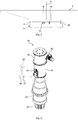
- Fig. 1 is a schematic side view of a wind turbine 1 can be seen, which is located in the sea and anchored in the seabed 2.
- the water level of the sea is schematically indicated and designated by the reference numeral 17.
- the wind power plant 1 comprises a supporting structure 3 in the form of a lattice tower, on which a machine carrier 4 is rotatably mounted about an azimuth bearing 5 about a vertical yaw axis 6.
- the machine frame 4 carries a machine house 7, in which an electric generator 8 is arranged.
- a rotor 9 is rotatably mounted about a rotor axis 10 which extends transversely or approximately transversely to the yaw axis 6.
- the rotor axis 10 is slightly inclined relative to the horizontal.
- the rotor 9 comprises a rotor hub 12 on which two rotor blades 13 and 14 are rotatably mounted about their respective blade axis 15 and 16, wherein the blade axes 15 and 16 extend transversely or approximately transversely to the rotor axis 10.
- the rotor hub 12 is rotationally rigidly connected to a rotor shaft (not shown), by means of which the rotor 9 is connected to the generator 8.
- the rotor 9 is rotated by wind 11 about its rotor axis 10 and drives the generator 8 at.
- Fig. 2 is a schematic side view of the machine frame 4 can be seen, are attached to the two control devices 18 and 19 according to an embodiment of the invention.
- the control devices 18 and 19 are of similar construction, wherein a perspective view of the control device 18 from Fig. 3 is apparent. Furthermore, a side view of the control device 18 is made Fig. 4 and a schematic sectional view of the control device 18 along the in Fig. 4 illustrated section line AA Fig. 5 seen.
- the control device 18 comprises an electric motor 20 whose motor shaft 21 is rotatable about an axis 54 and connected to an input shaft 22 of a transmission 23 with the interposition of an attenuator in the form of a hydraulic damper 28 and a brake device 44.
- An output shaft 24 of the transmission 23 is rotationally rigidly connected to a pinion 25, for example, directly or with the interposition of a coupling member.
- the output shaft 24, in particular with the interposition of a coupling member also rotatably connected to the pinion 25.
- the pinion 25 meshes with a ring gear 26 (see Fig. 2 ), which is rigidly connected to the support structure 3 and provided in the upper end region of the support structure 3.
- the motor shaft 21 is connected with its end facing away from the damper 28 with a motor brake 27 which comprises at least one electromagnet 29, by means of which the brake 27 is held against the force of a spring 39 in the released state, as long as a sufficiently large electric current through the electromagnet 29 flows.
- the brake 27 automatically stops its Fig. 5 apparent braking state and blocks the motor shaft 21 of the electric motor 20.
- the electric motor 20 includes a motor housing 31, which forms a stator of the electric motor 20 and includes electric stator windings 40.
- the motor shaft 21 comprises electric rotor windings 41 and forms a rotor of the electric motor 20.
- the transmission 23 comprises a transmission housing 32
- the damper 28 comprises a damper housing 33
- the brake 27 comprises a brake housing 42
- the braking device 44 comprises a housing 43.
- the electric motor 20 is further arranged in a first outer housing 34, wherein the brake 27 is arranged in a second outer housing 35.
- a fan 59 is provided, by means of which the electric motor 20 is cooled.
- the outer housing 34 and 35 may also be formed by a common outer housing or omitted. If the outer housings 34 and 35 form a common outer housing, then this is in particular ventilated with a fan.
- the housing 34 may also include the damper 28 and possibly the braking device 44.
- the housings 31, 32, 33, 34, 35, 42 and 43 are rigidly connected to each other. Furthermore, these housings are rigidly connected to the machine frame 4.
- the electric motor 20 is connected to an electrical network 38 via a control device 36 which comprises a frequency converter 37.
- the electrical network 38 forms a power supply for the control device 36 and the electric motor 20.
- the electromagnet 29 is or can be supplied with power from the electrical network 38.
- the machine carrier 4 follows this change in direction and rotates about the yaw axis 6. Since the wind turbine 1 is designed as a leeward rotor, the machine carrier 4 behaves approximately like a wind vane. In particular, the machine carrier 4 tries to align so that the rotor axis 10 is aligned in the wind direction 11. During this rotation, which is also referred to as yawing, the pinion 25 is rotated, which rotates the motor shaft 21 with the interposition of the transmission 23, the braking device 44 and the damper 28. The electric motor 20 is controlled by the control device 36 such that this rotational movement is damped. This is advantageous because abrupt wind direction changes can lead to heavy loads on the wind turbine 1.
- the control device 36 adjusts the damping in such a way that the load of the wind turbine 1 kept as low as possible.
- the electric motor 20, the gear 23 and the control device 36 together form an adjusting device.
- the damper 28 and / or the braking device 44 can be attributed to the adjusting device.
- the electromagnet 29 is energized and releases the motor shaft 21 again. Furthermore, the control device 36 resumes its operation and controls the damping of the yawing movements of the machine carrier 4.
- the electromagnet 29 can be separated from the power supply 38 by a switch 53 shown schematically.
- the electric motor 20 is preferably not controlled by the control device 36.
- a blocking of the motor shaft 21 in the presence of a power supply makes sense if the machine frame 4 is to remain in a certain position relative to the support structure 3. An attenuation of a particular wind-induced yaw movement of the machine frame 4 can then be ensured by the damper 28.
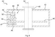
- the braking device 44 is provided, by means of which the machine carrier 4, in particular non-rotatably, on the support structure 3 can be fixed.
- the braking device 44 includes a yawing brake 30 and a shaft 45, on which the yawing brake 30 engages.
- the shaft 45 is connected between an output shaft 51 of the damper 28 and the input shaft 22 of the transmission 23 and connected in rotation with both the output shaft 51 of the damper 28 and with the input shaft 22 of the transmission 23.
- the shaft 45 is formed by the output shaft 51 of the damper 28 or by the input shaft 22 of the transmission 23.
- the shaft 45 and the output shaft 51 of the damper 28 are formed by the input shaft 22 of the transmission 23.
- an input shaft 50 of the damper 28 is rotationally rigidly connected to the motor shaft 21.
- the yaw brake 30 comprises a rotatably connected to the shaft 45 brake disk 46, a housing 43 movably mounted to the brake caliper 47 with a first brake pad 48, and a hydraulic brake cylinder 49 with brake piston 52 to which a second brake pad 58 is attached.
- the brake cylinder 49 includes a chamber 60 into which hydraulic fluid is introduced under pressure for actuating the yaw brake 30 so that the brake piston 52 moves and presses the brake pad 58 against one side of the brake disk 46. As a result, the brake caliper 47 is also moved and presses the brake pad 48 against the other side of the brake disk 46.
- the yaw brake 30 is embodied here as a hydraulically operated floating caliper brake whose brake carrier is formed by the housing 43.
- the yaw brake can also be operated electrically or pneumatically.
- the yaw brake can be designed as a fixed caliper brake. It is also possible that the yaw brake comprises a plurality of brake discs.
- the damper 28 includes an impeller 55 having an impeller housing 56 rotationally connected to the input shaft 50 of the damper 28 and an inner member 57 rotatable therein which is rotationally rigidly connected to the output shaft 51 of the damper 28. Further, a hydraulic fluid is introduced into the impeller housing 56.
- the damper 28 further comprises a brake, by means of which the impeller housing 56 is automatically blocked in case of failure of the power supply 38. Thus, it is possible to automatically activate the damping function of the damper in case of failure of the power supply 38.
- the brake of the damper 38 may be provided alternatively or in addition to the brake 27.
- control devices 18 and 19 are present.
- additional control devices are present, so that a stronger damping or braking force can be applied.
- control means 36 of all the control devices are networked together, so that when greater damping or braking force is required, additional control devices can be switched on. Is a weaker damping or braking force sufficient, which can be applied for example with only one or two control devices, the additional control devices can be disabled again.
Description
Die Erfindung betrifft eine Steuervorrichtung für ein Giersystem einer Windkraftanlage, mit wenigstens einer zwischen eine Tragstruktur und einen an der Tragsstruktur um eine Gierachse drehbar gelagerten Maschinenträger geschalteten und einen Antrieb und ein Getriebe umfassenden Stelleinrichtung und wenigstens einer Gierbremse, mittels welcher der Maschinenträger an der Tragstruktur festlegbar ist.The invention relates to a control device for a yawing system of a wind power plant, comprising at least one actuating device and at least one yawing brake connected between a support structure and a machine support rotatably mounted on the support structure about a yaw axis and at least one yaw brake, by means of which the machine support can be fixed to the support structure is.
Die
Die
Die
Die
Aus der
Bei blockierter Bremse wird eine durch Wind hervorgerufene Gierbewegung durch die Kupplung gedämpft. Zusätzlich können Gierbremsen vorgesehen sein, mit welchen eine Gierbewegung blockierbar ist. Ein Blockieren der Gierbewegung ist z.B. aus Sicherheitsgründen gewünscht, wenn Wartungspersonal an der Maschinenanlage und/oder im Bereich des Maschinenträgers arbeitet.When the brake is locked, wind-induced yawing is damped by the clutch. In addition, yaw brakes can be provided, with which a yawing motion can be blocked. Blocking the yawing motion is e.g. for safety reasons, if maintenance personnel work on the machine system and / or in the area of the machine carrier.
Herkömmliche Gierbremsen sind an der Schnittstelle von Tragstruktur und Maschinenträger, insbesondere am oder im Bereich des Gierlagers, angeordnet. Da die von den Gierbremseh aufzubringenden Bremskräfte groß sind, werden die Gierbremsen entsprechend stark ausgelegt, was mit nicht unerheblichen Kosten verbunden ist.Conventional yaw brakes are arranged at the interface of support structure and machine carrier, in particular on or in the region of the yaw bearing. Since the applied by the yaw braking forces are large, the yaw brakes are designed accordingly strong, which is associated with significant costs.
Ausgehend hiervon liegt der Erfindung die Aufgabe zugrunde, die Kosten für das Blockieren einer Gierbewegung reduzieren zu können.Proceeding from this, the object of the invention is to be able to reduce the costs for blocking a yawing movement.
Diese Aufgabe wird erfindungsgemäß durch eine Steuervorrichtung nach Anspruch 1 gelöst. Bevorzugte Weiterbildungen der Erfindung sind in den Unteransprüchen und in der nachfolgenden Beschreibung gegeben.This object is achieved by a control device according to
Die erfindungsgemäße Steuervorrichtung, insbesondere für ein Giersystem einer Windkraftanlage, weist wenigstens eine zwischen eine Tragstruktur und einen an der Tragsstruktur um eine Gierachse drehbar gelagerten Maschinenträger geschaltete und einen Antrieb und ein, insbesondere mit diesem gekoppeltes, Getriebe umfassende Stelleinrichtung und wenigstens eine Gierbremse auf, mittels welcher der Maschinenträger, insbesondere unverdrehbar, an der Tragstruktur festlegbar ist, wobei die Gierbremse zwischen dem Antrieb und dem Getriebe am Triebstrang der Stelleinrichtung angreift.The control device according to the invention, in particular for a yaw system of a wind power plant, has at least one adjusting device connected between a support structure and a machine carrier rotatably mounted about a yaw axis and having a drive and a gearbox, in particular coupled thereto, and at least one yaw brake which the machine carrier, in particular non-rotatable, can be fixed to the support structure, wherein the yaw brake engages between the drive and the transmission on the drive train of the actuating device.
Zwischen dem Antrieb und dem Getriebe reichen vergleichsweise kleine Bremskräfte aus, um das Getriebe und somit auch eine Drehung des Maschinenträgers um die Gierachse zu blockieren. Grund dafür ist das Übersetzungsverhältnis des Getriebes, welches insbesondere größer als 1, vorzugsweise sogar größer als 100 oder 1000, ist. Aus diesem Grund kann die Gierbremse schwächer ausgebildet werden, wodurch Kosten eingespart werden können.Between the drive and the transmission comparatively small braking forces are sufficient to block the transmission and thus also a rotation of the machine carrier about the yaw axis. The reason for this is the transmission ratio of the transmission, which in particular is greater than 1, preferably even greater than 100 or 1000, is. For this reason, the yaw brake can be made weaker, whereby costs can be saved.
Das Getriebe ist insbesondere eingangsseitig mit dem Antrieb und ausgangsseitig mit dem Maschinenträger oder mit der Tragstruktur gekoppelt. Bevorzugt umfasst das Getriebe eine mit dem Antrieb gekoppelte Eingangswelle und eine mit dem Maschinenträger oder mit der Tragstruktur gekoppelte Ausgangswelle. Das Getriebe ist vorzugsweise ein Untersetzungsgetriebe. Vorteilhaft ist die Ausgangswelle des Getriebes drehstarr mit der Eingangswelle des Getriebes gekoppelt. Insbesondere ist das Getriebe ein Zahnradgetriebe.The transmission is in particular coupled on the input side with the drive and on the output side with the machine carrier or with the support structure. Preferably, the transmission comprises an input shaft coupled to the drive and an output shaft coupled to the machine carrier or to the support structure. The transmission is preferably a reduction gear. Advantageously, the output shaft of the transmission is torsionally coupled with the input shaft of the transmission. In particular, the transmission is a gear transmission.
Bevorzugt greift die Gierbremse an einer Welle der Stelleinrichtung an, mittels welcher das Getriebe mit dem Antrieb gekoppelt oder koppelbar ist. Diese Welle ist z.B. durch die Eingangswelle des Getriebes gebildet oder drehstarr mit dieser verbunden.Preferably, the yawing brake engages a shaft of the adjusting device, by means of which the transmission is coupled to the drive or can be coupled. This wave is e.g. formed by the input shaft of the transmission or torsionally rigidly connected thereto.
Bevorzugt ist der Antrieb ein elektrischer Antrieb. Insbesondere ist oder umfasst der Antrieb eine oder wenigstens eine elektrische Maschine, beispielsweise einen oder wenigstens einen Elektromotor. Alternativ kann der Antrieb aber auch ein hydraulischer Antrieb oder ein anderer Antrieb sein.The drive is preferably an electric drive. In particular, the drive is or comprises one or at least one electric machine, for example one or at least one electric motor. Alternatively, the drive can also be a hydraulic drive or another drive.
Vorteilhaft ist eine elektrische Stromversorgung vorgesehen, die insbesondere eine Stromversorgung für den Antrieb bildet. Vorzugsweise ist der Antrieb mittels der Stromversorgung mit elektrischem Strom versorgbar. Dies gilt insbesondere dann, wenn der Antrieb ein elektrischer Antrieb, wie z.B. ein Elektromotor, ist. Handelt es sich bei dem Antrieb um einen anderen Antrieb, wie z.B. um einen hydraulischen Antrieb, so wird bevorzugt auch dieser, insbesondere mittelbar, durch die Stromversorgung versorgt. Beispielsweise umfasst der hydraulische Antrieb wenigstens eine elektrisch betriebene Hydraulikpumpe, die vorzugsweise mittels der Stromversorgung mit elektrischem Strom versorgt wird. Bevorzugt ist der Antrieb mittels der Stromversorgung unmittelbar oder mittelbar mit elektrischem Strom versorgbar. Insbesondere fällt bei einem Ausfall der Stromversorgung auch der Antrieb aus. Die Stromversorgung ist beispielsweise durch ein elektrisches Netz gegeben. Ferner kann die Stromversorgung eine Notstromversorgung umfassen. Der elektrische Strom kann ein Gleichstrom oder ein Wechselstrom, insbesondere ein Drehstrom sein. Das elektrische Netz ist bevorzugt ein Wechselstromnetz, vorzugsweise ein Drehstromnetz.Advantageously, an electrical power supply is provided, which in particular forms a power supply for the drive. Preferably, the drive can be supplied with electrical power by means of the power supply. This is especially true when the drive is an electric drive, such as an electric motor. If the drive is another drive, such as a hydraulic drive, then it is also preferably supplied by the power supply, in particular indirectly. For example, the hydraulic drive comprises at least one electrically operated hydraulic pump, which is preferably supplied with electrical current by means of the power supply. Preferably, the drive by means of the power supply directly or indirectly supplied with electric power. In particular, fails in a failure of the power supply and the drive. The power supply is for example by an electrical network given. Furthermore, the power supply may include an emergency power supply. The electric current may be a direct current or an alternating current, in particular a three-phase current. The electrical network is preferably an AC network, preferably a three-phase network.
Eine Drehung oder Drehbewegung des Maschinenträgers relativ zu der Tragstruktur um die Gierachse ist bevorzugt mittels der Stelleinrichtung, insbesondere mittels des Antriebs, steuerbar oder regelbar. Vorteilhaft ist wenigstens eine Steuereinrichtung vorgesehen, mittels welcher der Antrieb steuerbar oder regelbar ist. Insbesondere ist der Antrieb, vorzugsweise mittels der Steuereinrichtung, derart steuerbar oder regelbar, dass eine Drehung oder Drehbewegung des Maschinenträgers relativ zu der Tragstruktur um die Gierachse erzeugbar und/oder bremsbar und/oder dämpfbar ist. Die Steuereinrichtung ist bevorzugt eine elektrische Steuereinrichtung und vorteilhaft elektrisch mit dem Antrieb verbunden. Insbesondere umfasst die Steuereinrichtung einen oder wenigstens einen Umrichter und/oder Frequenzumrichter. Vorzugsweise ist mittels der Steuereinrichtung der dem Antrieb zugeführte oder zuführbare Strom steuerbar oder regelbar. Bevorzugt ist mittels der Steuereinrichtung die Stromstärke und/oder Amplitude und/oder Frequenz und/oder Phase dieses Stroms steuerbar oder regelbar. Insbesondere ist die Steuereinrichtung mittels der Stromversorgung mit elektrischem Strom versorgbar.A rotation or rotational movement of the machine carrier relative to the support structure about the yaw axis is preferably controllable or controllable by means of the adjusting device, in particular by means of the drive. Advantageously, at least one control device is provided by means of which the drive can be controlled or regulated. In particular, the drive, preferably by means of the control device, can be controlled or regulated such that rotation or rotational movement of the machine carrier relative to the support structure can be generated and / or braked and / or damped about the yaw axis. The control device is preferably an electrical control device and advantageously electrically connected to the drive. In particular, the control device comprises one or at least one converter and / or frequency converter. Preferably, by means of the control device, the power supplied or supplied to the drive can be controlled or regulated. Preferably, the current intensity and / or amplitude and / or frequency and / or phase of this current can be controlled or regulated by means of the control device. In particular, the control device can be supplied with electric current by means of the power supply.
An dem Maschinenträger ist bevorzugt ein durch Wind um eine Rotorachse drehbarer Rotor drehbar gelagert. Die Rotorachse ist vorzugsweise quer oder näherungsweise quer zur Gierachse ausgerichtet. Insbesondere ist die Rotorachse horizontal oder näherungsweise horizontal ausgerichtet. Bevorzugt ist die Rotorachse gegenüber der Horizontalen geringfügig geneigt. Vorteilhaft ist der Rotor an der Lee-Seite des Maschinenträgers angeordnet. Alternativ kann der Rotor aber auch an der Luv-Seite des Maschinenträgers angeordnet sein.On the machine support a rotatable by wind about a rotor axis rotatable rotor is preferably mounted. The rotor axis is preferably aligned transversely or approximately transversely to the yaw axis. In particular, the rotor axis is oriented horizontally or approximately horizontally. Preferably, the rotor axis is slightly inclined relative to the horizontal. The rotor is advantageously arranged on the leeward side of the machine carrier. Alternatively, however, the rotor can also be arranged on the windward side of the machine carrier.
Der Rotor umfasst bevorzugt eine Rotornabe und ein oder mehrere an der Rotornabe gelagerte Rotorblätter, die sich insbesondere quer oder näherungsweise quer zur Rotorachse von der Rotornabe wegerstrecken. Vorzugsweise ist das oder jedes der Rotorblätter an der Rotornabe um eine Blattachse drehbar gelagert, die insbesondere quer oder näherungsweise quer zur Rotorachse verläuft. Die Anzahl der Rotorblätter beträgt bevorzugt eins, wenigstens eins, zwei, wenigstens zwei, drei oder wenigstens drei. Insbesondere sind die Rotorblätter rings der Rotorachse gleichmäßig verteilt angeordnet.The rotor preferably comprises a rotor hub and one or more rotor blades mounted on the rotor hub, which extend in particular transversely or approximately transversely to the rotor axis away from the rotor hub. Preferably, the or each of the rotor blades is rotatably mounted on the rotor hub about a blade axis, which in particular runs transversely or approximately transversely to the rotor axis. The number of rotor blades is preferably one, at least one, two, at least two, three or at least three. In particular, the rotor blades are arranged distributed uniformly around the rotor axis.
Der Maschinenträger trägt bevorzugt einen elektrischen Generator, der von dem Rotor antreibbar ist. Insbesondere ist der Generator mit einer Rotorwelle des Rotors verbunden. Zwischen den Generator und den Rotor und/oder zwischen den Generator und die Rotorwelle kann ein Rotorgetriebe geschaltet sein.The machine carrier preferably carries an electrical generator that can be driven by the rotor. In particular, the generator is connected to a rotor shaft of the rotor. A rotor gear can be connected between the generator and the rotor and / or between the generator and the rotor shaft.
Die Tragstruktur umfasst oder bildet bevorzugt einen Turm, der insbesondere mit einem Fundament oder einer Gründung im Erdboden oder Seeboden verankert ist. Die Längsachse der Tragstruktur und/oder des Turms fällt bevorzugt mit der Gierachse zusammen. Insbesondere ist die Gierachse vertikal oder näherungsweise vertikal ausgerichtet. Der Maschinenträger ist vorzugsweise auf der Tragstruktur angeordnet.The support structure preferably comprises or forms a tower, which is anchored in particular with a foundation or foundation in the ground or seabed. The longitudinal axis of the support structure and / or the tower preferably coincides with the yaw axis. In particular, the yaw axis is oriented vertically or approximately vertically. The machine carrier is preferably arranged on the support structure.
Der Antrieb umfasst bevorzugt eine Antriebswelle, die insbesondere mittels des Antriebs drehbar ist. Ist oder umfasst der Antrieb einen Motor oder Elektromotor, so handelt es sich bei der Antriebswelle insbesondere um die Motorwelle des Motors oder Elektromotors oder z.B. um eine mit der Motorwelle des Motors oder Elektromotors drehstarr verbundene Welle. Ferner umfasst der Antrieb vorzugsweise einen Ständer und einen relativ zu diesem drehbaren Läufer, der insbesondere die Antriebswelle umfasst und/oder starr oder drehstarr mit dieser verbunden ist. Der Ständer umfasst bevorzugt wenigstens eine, vorzugsweise mehrere, elektrische Ständerwicklungen. Der Läufer umfasst bevorzugt wenigstens eine, vorzugsweise mehrere, elektrische Läuferwicklungen. Der Läufer kann auch als Käfigläufer ausgebildet sein, sodass die Läuferwicklung insbesondere mehrere Leiterstäbe umfasst, die an ihren Enden elektrisch miteinander verbunden, vorzugsweise kurzgeschlossen, sind. In diesem Fall bildet oder umfasst der Antrieb z.B. eine Asynchronmaschine. Der Antrieb kann auch als permanenterregter Elektromotor ausgebildet sein. In diesem Fall trägt der Läufer oder der Ständer wenigstens einen, vorzugsweise mehrere, Permanentmagnete, insbesondere anstelle der jeweiligen Wicklung oder Wicklungen. Bevorzugt ist der Antrieb somit ein Elektromotor, der beispielsweise als Gleichstrommotor oder als Wechselstrommotor, insbesondere als Drehstrommotor ausgebildet ist.The drive preferably comprises a drive shaft, which is rotatable in particular by means of the drive. If the drive is or comprises a motor or an electric motor, then the drive shaft is, in particular, the motor shaft of the motor or electric motor or, for example, a shaft connected torsionally rigid with the motor shaft of the motor or electric motor. Furthermore, the drive preferably comprises a stator and a rotor rotatable relative thereto, which in particular comprises the drive shaft and / or is rigidly or rotationally rigidly connected thereto. The stator preferably comprises at least one, preferably a plurality, electric stator windings. The rotor preferably comprises at least one, preferably a plurality of, electrical rotor windings. The rotor can also be designed as a squirrel-cage rotor, so that the rotor winding in particular comprises a plurality of conductor bars, which are electrically connected to one another at their ends, preferably short-circuited. In this case, the drive forms or comprises, for example, an asynchronous machine. The drive can also be designed as a permanent-magnet electric motor. In In this case, the rotor or the stator carries at least one, preferably a plurality of permanent magnets, in particular instead of the respective winding or windings. The drive is thus preferably an electric motor which is designed, for example, as a DC motor or as an AC motor, in particular as a three-phase motor.
Der Ständer des Antriebs ist bevorzugt fest, insbesondere starr oder drehstarr, mit dem Maschinenträger oder mit der Tragstruktur verbunden. Vorzugsweise umfasst der Antrieb ein starr oder drehstarr mit dem Ständer verbundenes und/oder diesen umfassendes Antriebs- oder Motorgehäuse. Vorteilhaft ist das Antriebs- oder Motorgehäuse fest, insbesondere starr oder drehstarr, mit dem Maschinenträger oder mit der Tragstruktur verbunden.The stator of the drive is preferably fixed, in particular rigid or torsionally rigid, connected to the machine carrier or to the support structure. Preferably, the drive comprises a rigidly or torsionally rigid connected to the stand and / or this comprehensive drive or motor housing. Advantageously, the drive or motor housing is fixed, in particular rigid or torsionally rigid, connected to the machine carrier or to the support structure.
Die Stelleinrichtung umfasst bevorzugt eine Ausgangswelle, die, insbesondere drehstarr, mit dem Maschinenträger oder mit der Tragstruktur verbunden oder gekoppelt ist. Vorteilhaft ist mit der Ausgangswelle ein Ritzel, insbesondere starr oder drehstarr oder elastisch, verbunden, welches mit einem Zahnkranz kämmt und/oder ineinander greift, der, vorzugsweise fest, insbesondere starr oder drehstarr oder verwindungsweich, mit dem Maschinenträger oder der Tragstruktur verbunden ist. Vorteilhaft ist die Ausgangswelle der Stelleinrichtung, vorzugsweise drehelastisch oder fest, insbesondere starr oder drehstarr, mit der Ausgangswelle des Getriebes verbunden oder durch diese gebildet.The adjusting device preferably comprises an output shaft, which, in particular torsionally rigid, is connected or coupled to the machine carrier or to the supporting structure. Advantageously, with the output shaft, a pinion, in particular rigid or torsionally rigid or elastic, connected, which meshes with a ring gear and / or interlocking, which is preferably fixed, in particular rigid or torsionally rigid or torsionally soft, connected to the machine frame or the support structure. Advantageously, the output shaft of the adjusting device, preferably torsionally elastic or fixed, in particular rigid or torsionally rigid, connected to the output shaft of the transmission or formed by this.
Bevorzugt ist der Maschinenträger durch Wind relativ zu der Tragstruktur um die Gierachse drehbar. Vorteilhaft ist der Rotor dabei an der Lee-Seite des Maschinenträgers angeordnet. Insbesondere handelt es sich bei dem Giersystem um ein passives Giersystem.Preferably, the machine frame is rotatable about the yaw axis relative to the support structure by wind. Advantageously, the rotor is arranged on the lee side of the machine carrier. In particular, the yaw system is a passive yaw system.
Gemäß einer Ausgestaltung ist der Antrieb, vorzugsweise mittels der Steuereinrichtung, als Dämpfer betreibbar, mittels welchem eine, insbesondere durch Wind hervorgerufene, Drehung oder Drehbewegung des Maschinenträgers relativ zu der Tragstruktur um die Gierachse dämpfbar ist. Dieser Dämpfer bildet bevorzugt einen aktiven Dämpfer. Darunter ist insbesondere zu verstehen, dass dieser Dämpfer bei Ausfall der Stromversorgung nicht funktionsfähig ist und/oder dass die dämpfende Eigenschaft dieses Dämpfers und/oder die Dämpfung der oder einer Drehung oder Drehbewegung des Maschinenträgers relativ zu der Tragstruktur um die Gierachse mittels der Steuereinrichtung steuerbar ist.According to one embodiment, the drive, preferably by means of the control device, can be operated as a damper, by means of which a rotation or rotational movement of the machine carrier, in particular caused by wind, can be damped about the yaw axis relative to the support structure. This damper preferably forms an active damper. This is to be understood in particular that this damper in case of failure the power supply is not functional and / or that the damping property of this damper and / or the damping of or rotation or rotational movement of the machine frame relative to the support structure about the yaw axis is controllable by means of the control device.
Erfindungsgemäß ist ein Dämpfungsglied vorgesehen, mittels welchem oder mit Hilfe dessen eine, insbesondere durch Wind hervorgerufene, Drehbewegung des Maschinenträgers relativ zu der Tragstruktur um die Gierachse dämpfbar ist. Das Dämpfungsglied ist ein passives Dämpfungsglied. Darunter ist insbesondere zu verstehen, dass das Dämpfungsglied auch bei Ausfall der Stromversorgung funktionsfähig ist und/oder dass die dämpfende Eigenschaft des Dämpfungsglieds und/oder die Dämpfung der oder einer Drehbewegung des Maschinenträgers relativ zu der Tragstruktur um die Gierachse nicht aktiv steuerbar ist. Allerdings kann die Dämpfung abhängig von der Geschwindigkeit und/oder einer Geschwindigkeitsänderung der Drehbewegung des Maschinenträgers relativ zu der Tragstruktur um die Gierachse sein. Das Dämpfungsglied ist bevorzugt in den Triebstrang der Stelleinrichtung geschaltet. Insbesondere umfasst die Stelleinrichtung das Dämpfungsglied. Vorteilhaft umfasst das Dämpfungsglied eine Eingangswelle und eine Ausgangswelle.According to the invention, an attenuator is provided, by means of which or with the aid of which, in particular caused by wind, rotational movement of the machine carrier relative to the support structure can be damped about the yaw axis. The attenuator is a passive attenuator. This is to be understood in particular that the attenuator is functional even in case of power failure and / or that the damping property of the attenuator and / or the damping of or rotational movement of the machine frame relative to the supporting structure about the yaw axis is not actively controlled. However, the damping may be dependent on the speed and / or a speed change of the rotational movement of the machine frame relative to the support structure about the yaw axis. The attenuator is preferably connected in the drive train of the actuating device. In particular, the adjusting device comprises the attenuator. Advantageously, the attenuator comprises an input shaft and an output shaft.
Bevorzugt bildet oder umfasst das Dämpfungsglied einen hydraulischen Dämpfer. Bei dem hydraulischen Dämpfer handelt es sich z.B. um eine hydrodynamische Kupplung oder Visko-Kupplung. Vorteilhaft umfasst das Dämpfungsglied einen Impeller mit einem Impellergehäuse und einem in diesem drehbaren Innenteil, welches vorzugsweise fest, insbesondere starr oder drehstarr, mit einer der Wellen des Dämpfungsglieds, beispielsweise mit der Ausgangswelle des Dämpfungsglieds, verbunden ist. Das Impellergehäuse ist vorzugsweise fest, insbesondere starr oder drehstarr, mit einer anderen der Wellen des Dämpfungsglieds, beispielsweise mit der Eingangswelle des Dämpfungsglieds, verbunden. Alternativ ist das Innenteil z.B. fest, insbesondere starr oder drehstarr, mit der Eingangswelle des Dämpfungsglieds, verbunden, wobei das Impellergehäuse z.B. fest, insbesondere starr oder drehstarr, mit der Ausgangswelle des Dämpfungsglieds verbunden ist. Das Innenteil ist z.B. ein Propeller. Vorteilhaft ist in dem Gehäuse eine Flüssigkeit, insbesondere eine Hydraulikflüssigkeit vorgesehen. Das Dämpfungsglied ist bevorzugt zwischen den Antrieb und das Getriebe geschaltet.Preferably, the attenuator forms or comprises a hydraulic damper. The hydraulic damper is, for example, a hydrodynamic coupling or viscous coupling. Advantageously, the attenuator comprises an impeller with an impeller housing and a rotatable inner part in this, which is preferably fixed, in particular rigid or torsionally rigid, with one of the waves of the attenuator, for example, with the output shaft of the attenuator is connected. The impeller housing is preferably fixed, in particular rigid or torsionally rigid, with another of the waves of the attenuator, for example, connected to the input shaft of the attenuator. Alternatively, the inner part, for example, fixed, in particular rigid or torsionally rigid, connected to the input shaft of the attenuator, wherein the impeller housing, for example, fixed, in particular rigid or torsionally rigid, is connected to the output shaft of the attenuator. The inner part is eg a propeller. Advantageously, a liquid, in particular a hydraulic fluid is provided in the housing. The attenuator is preferably connected between the drive and the transmission.
Erfindungsgemäß greift die Gierbremse zwischen dem Dämpfungsglied und dem Getriebe am Triebstrang der Stelleinrichtung an. Somit kann vermieden werden, dass das Dämpfungsglied trotz betätigter Gierbremse eine Drehung des Maschinenträgers relativ zu der Tragstruktur um die Gierachse zulässt.According to the invention, the yaw brake engages between the damping member and the transmission on the drive train of the actuating device. Thus, it can be avoided that the attenuator, despite actuated yaw brake allows rotation of the machine frame relative to the support structure about the yaw axis.
Bevorzugt greift die Gierbremse an einer Welle der Stelleinrichtung an, mittels welcher das Getriebe mit dem Dämpfungsglied gekoppelt oder koppelbar ist. Die Welle, an welcher die Gierbremse angreift, ist z.B. durch die Eingangswelle des Getriebes gebildet oder drehstarr mit dieser verbunden, und/oder die Welle, an welcher die Gierbremse angreift, ist z.B. durch die Ausgangswelle des Dämpfungsglieds gebildet oder drehstarr mit dieser verbunden. Insbesondere ist die Welle, an welcher die Gierbremse angreift, zwischen der Ausgangswelle des Dämpfungsglieds und der Eingangswelle des Getriebes angeordnet und/oder zwischen die Ausgangswelle des Dämpfungsglieds und die Eingangswelle des Getriebes geschaltet. In diesem Fall ist die Welle, an welcher die Gierbremse angreift, insbesondere drehstarr mit der Ausgangswelle des Dämpfungsglieds und drehstarr mit der Eingangswelle des Getriebes verbunden.Preferably, the yawing brake engages a shaft of the adjusting device, by means of which the transmission is coupled to the damping member or can be coupled. The shaft on which the yaw brake engages is e.g. formed by the input shaft of the transmission or torsionally rigidly connected thereto, and / or the shaft on which the yaw brake engages, is e.g. formed by the output shaft of the attenuator or torsionally rigidly connected thereto. In particular, the shaft on which the yaw brake engages, disposed between the output shaft of the attenuator and the input shaft of the transmission and / or connected between the output shaft of the attenuator and the input shaft of the transmission. In this case, the shaft on which the yaw brake engages, in particular torsionally rigid with the output shaft of the attenuator and torsionally rigidly connected to the input shaft of the transmission.
Mittels der Gierbremse ist bevorzugt der Triebstrang der Stelleinrichtung und/oder ein Teil dieses Triebstrangs blockierbar. Der Triebstrang und/oder der mittels der Gierbremse blockierbare Teil des Triebstrangs umfasst insbesondere das Getriebe. Beispielsweise ist mittels der Gierbremse das Getriebe, insbesondere von seiner Eingangsseite her, blockierbar. Vorteilhaft ist mittels der Gierbremse die Welle, an welcher die Gierbremse angreift, bremsbar und/oder blockierbar.By means of the yaw brake, the drive train of the adjusting device and / or a part of this drive train is preferably blockable. The drive train and / or the blockable by means of the yaw brake part of the drive train includes in particular the transmission. For example, the transmission, in particular from its input side, can be blocked by means of the yaw brake. Advantageously, by means of the yaw brake, the shaft on which the yaw brake engages, braked and / or blocked.
Die Gierbremse ist bevorzugt eine Scheibenbremse. Bevorzugt umfasst die Gierbremse wenigstens eine Bremsscheibe und wenigstens einen Bremskörper, der gegen die Bremsscheibe drückbar ist. Der Bremskörper umfasst z.B. einen oder wenigstens einen Bremsklotz und/oder einen oder wenigstens einen Bremssattel und/oder einen oder wenigstens einen Bremskolben und/oder einen oder wenigstens einen Bremsbelag. Insbesondere ist die Bremsscheibe drehstarr mit dem Triebstrang und/oder mit dem mittels der Gierbremse blockierbaren Teil des Triebstrangs verbunden. Bevorzugt ist die Bremsscheibe drehstarr mit der Welle, an welcher die Gierbremse angreift, verbunden.The yaw brake is preferably a disc brake. The yaw brake preferably comprises at least one brake disk and at least one brake body that can be pressed against the brake disk. The brake body includes, for example, one or at least one brake pad and / or one or at least one caliper and / or one or at least one brake piston and / or one or at least one brake pad. In particular, the brake disc is torsionally rigidly connected to the drive train and / or to the blockable by means of the yaw brake part of the drive train. Preferably, the brake disc is torsionally rigid with the shaft on which the yaw brake engages connected.
Bevorzugt ist eine Bremseinrichtung vorgesehen, welche die Gierbremse und die oder eine Welle aufweist, an welcher die Gierbremse angreift. Die Bremseinrichtung ist bevorzugt, insbesondere mit ihrer Welle, zwischen den Antrieb und das Getriebe, vorzugsweise zwischen das Dämpfungsglied und das Getriebe, geschaltet.Preferably, a braking device is provided which has the yaw brake and the or a shaft on which the yaw brake engages. The braking device is preferably connected, in particular with its shaft, between the drive and the transmission, preferably between the damping element and the transmission.
Gemäß einer Ausgestaltung bildet die Gierbremse im betätigten Zustand eine Rutschkupplung, die bei Erreichen oder Überschreiten eines Losbrechmoments eine Drehung des Maschinenträgers relativ zu der Tragstruktur um die Gierachse zulässt. Somit lassen sich Überlastungen vermeiden, die zu einer Beschädigung des Maschinenträgers und/oder der Tragstruktur und/oder anderer Komponenten der Windkraftanlage führen können.According to one embodiment, the yaw brake in the actuated state forms a slip clutch which, when a breakaway torque is reached or exceeded, permits a rotation of the machine carrier relative to the support structure about the yaw axis. Thus, overloads can be avoided, which can lead to damage to the machine frame and / or the support structure and / or other components of the wind turbine.
Erfindungsgemäß ist eine Antriebsbremse vorgesehen, mittels welcher der Antrieb bremsbar und/oder blockierbar ist. Bevorzugt ist die Antriebsbremse mit der Antriebswelle, insbesondere fest, vorzugsweise starr oder drehstarr, verbunden. Die Antriebsbremse ist insbesondere in Kombination mit dem Dämpfungsglied sinnvoll, sodass bei gebremstem oder blockiertem Antrieb eine Dämpfung einer, insbesondere durch Wind hervorgerufenen, Drehbewegung des Maschinenträgers relativ zu der Tragstruktur um die Gierachse möglich ist. Vorteilhaft ist bei Ausfall der Stromversorgung der Antrieb mittels der Antriebsbremse, insbesondere automatisch, bremsbar und/oder blockierbar. Die Antriebsbremse ist bevorzugt in den bremsenden und/oder blockierenden Zustand vorgespannt, insbesondere durch wenigstens eine Feder. Vorteilhaft ist die Antriebsbremse durch wenigstens einen Elektromagneten in den gelösten Zustand überführbar, insbesondere gegen die Kraft der Feder. Der Elektromagnet ist dazu bevorzugt mit elektrischem Strom versorgbar, der insbesondere von der Stromversorgung zur Verfügung stellbar ist. Der Antrieb ist vorzugsweise zwischen die Antriebsbreme und das Dämpfungsglied geschaltet. Handelt es sich bei dem Antrieb um einen Motor oder Elektromotor, kann die Antriebsbremse auch als Motorbremse bezeichnet werden.According to the invention, a drive brake is provided by means of which the drive can be braked and / or blocked. Preferably, the drive brake with the drive shaft, in particular fixed, preferably rigid or torsionally rigid, connected. The drive brake is particularly useful in combination with the attenuator, so that when braked or blocked drive damping of a, in particular caused by wind, rotational movement of the machine support relative to the support structure about the yaw axis is possible. It is advantageous in case of failure of the power supply of the drive means of the drive brake, in particular automatically, braked and / or blocked. The drive brake is preferably biased in the braking and / or blocking state, in particular by at least one spring. Advantageously, the drive brake can be converted by at least one electromagnet in the dissolved state, in particular against the force of the spring. The electromagnet is preferably supplied with electric power, in particular of the power supply is available. The drive is preferably connected between the drive brake and the attenuator. If the drive is a motor or an electric motor, the drive brake may also be referred to as an engine brake.
Gemäß einer Ausgestaltung ist mit dem Antrieb die oder eine Steuereinrichtung verbunden, insbesondere elektrisch verbunden, mittels welcher der Antrieb, insbesondere bei vorhandener Stromversorgung, steuerbar oder regelbar ist. Vorteilhaft ist die oder eine, insbesondere durch Wind hervorgerufene, Drehung oder Drehbewegung des Maschinenträgers relativ zu der Tragstruktur um die Gierachse durch den Antrieb dämpfbar. Wie oben bereits angesprochen, wird der Antrieb somit insbesondere nicht zum Drehen des Maschinenträgers, sondern vorzugsweise zum Dämpfen der oder einer, insbesondere durch Wind hervorgerufenen, Drehung oder Drehbewegung des Maschinenträgers relativ zu der Tragstruktur um die Gierachse eingesetzt. Dies ist insbesondere dann sinnvoll, wenn der Rotor auf der Lee-Seite des Maschinenträgers angeordnet ist. In diesem Fall ist der Maschinenträger durch den Wind in eine Stellung drehbar, in welcher die Rotorachse parallel oder näherungsweise parallel zur Windrichtung ausgerichtet ist. Dies funktioniert im Prinzip wie bei einer Windfahne. Die erfindungsgemäße Steuervorrichtung bildet in diesem Sinne bevorzugt eine Dämpfungsvorrichtung. Da es aufgrund von Turbulenzen, Windböen, Windscherung etc. zu einer ungewollten Drehbewegung des Maschinenträges kommen kann, welche diesen aus der gewünschten Position herausdreht, ist eine solche Drehbewegung mittels des Antriebs durch Aufbau eines Gegenmoments dämpfbar. Im Falle eines Stromausfalls und/oder bei gebremsten und/oder blockiertem Antrieb übernimmt diese Dämpfungsfunktion insbesondere das Dämpfungsglied. Bevorzugt ist es auch möglich, den Maschinenträger aktiv mittels des Antriebs zu drehen. Die erfindungsgemäße Steuervorrichtung bildet in diesem Sinne insbesondere eine Antriebsvorrichtung. Dies ist z.B. bei Korrekturen eines größeren Gierfehlers oder zu Wartungszwecken sinnvoll, beispielsweise um eine Verdrehung von zwischen dem Maschinenträger und der Tragstruktur verlaufenen Leitungen rückgängig zu machen. Ferner ist ein aktives Drehen des Maschinenträgers dann sinnvoll, wenn der Rotor auf der Luv-Seite des Maschinenträgers angeordnet ist. Bevorzugt bildet die erfindungsgemäße Steuervorrichtung eine Dämpfungs- und/oder Antriebsvorrichtung.According to one embodiment, the or a control device is connected to the drive, in particular electrically connected, by means of which the drive, in particular with existing power supply, can be controlled or regulated. Advantageously, the or one, in particular caused by wind, rotation or rotational movement of the machine carrier relative to the support structure about the yaw axis by the drive can be damped. As already mentioned above, the drive is thus not used in particular for rotating the machine carrier, but preferably for damping the or a, in particular caused by wind, rotation or rotational movement of the machine carrier relative to the support structure about the yaw axis. This is particularly useful when the rotor is arranged on the lee side of the machine carrier. In this case, the machine carrier is rotatable by the wind in a position in which the rotor axis is aligned parallel or approximately parallel to the wind direction. This works in principle like a wind vane. The control device according to the invention preferably forms a damping device in this sense. Since it may come due to turbulence, gusts of wind, wind shear, etc. to an unwanted rotational movement of the machine support, which turns out of the desired position, such a rotational movement by means of the drive by building a counter-torque is damped. In the case of a power failure and / or braked and / or blocked drive this damping function assumes in particular the attenuator. Preferably, it is also possible to actively rotate the machine frame by means of the drive. The control device according to the invention forms in this sense in particular a drive device. This is eg for corrections of a larger yaw error or for maintenance purposes useful, for example, to undo a rotation of running between the machine frame and the support structure lines. Furthermore, an active rotation of the machine carrier is useful if the rotor is arranged on the windward side of the machine carrier. Preferably, the control device according to the invention forms a damping and / or drive device.
Der Triebstrang der Stelleinrichtung umfasst insbesondere alle Komponenten der Stelleinrichtung, mit welchen eine Bewegung, vorzugsweise eine Drehbewegung, zwischen dem Antrieb und der Ausgangsseite des Getriebes und/oder der Ausgangswelle des Getriebes und/oder der Ausgangswelle der Stelleinrichtung übertragbar ist oder übertragen wird. Bevorzugt umfasst der Triebstrang das Getriebe und/oder die Eingangswelle des Getriebes und/oder die Ausgangswelle des Getriebes und/oder die Antriebswelle und/oder die Ausgangswelle der Stelleinrichtung und/oder das Dämpfungsglied und/oder die Eingangswelle des Dämpfungsglieds und/oder die Ausgangswelle des Dämpfungsglieds und/oder den Impeller.The drive train of the adjusting device comprises in particular all components of the adjusting device, with which a movement, preferably a rotational movement, between the drive and the output side of the transmission and / or the output shaft of the transmission and / or the output shaft of the actuating device is transferable or transmitted. Preferably, the driveline comprises the transmission and / or the input shaft of the transmission and / or the output shaft of the transmission and / or the drive shaft and / or the output shaft of the actuator and / or the attenuator and / or the input shaft of the attenuator and / or the output shaft of the Attenuator and / or the impeller.
Die Erfindung betrifft ferner eine Windkraftanlage mit einer Tragstruktur, einem an der Tragstruktur um eine Gierachse drehbar gelagerten Maschinenträger und wenigstens einer Steuervorrichtung, die wenigstens eine zwischen die Tragstruktur und den Maschinenträger geschaltete und einen Antrieb und ein, insbesondere mit diesem gekoppeltes, Getriebe umfassende Stelleinrichtung und wenigstens eine Gierbremse aufweist, mittels welcher der Maschinenträger, insbesondere unverdrehbar, an der Tragstruktur festlegbar ist, wobei die Gierbremse zwischen dem Antrieb und dem Getriebe am Triebstrang der Stelleinrichtung angreift. Bei der Steuervorrichtung handelt es sich insbesondere um erfindungsgemäße Steuervorrichtungen, die gemäß allen in diesem Zusammenhang erläuterten Ausgestaltungen weitergebildet sein kann. Die Windkraftanlage kann ein Luv-Läufer oder ein Lee-Läufer sein. Bevorzugt handelt es sich bei der Windkraftanlage aber um einen Lee-Läufer.The invention further relates to a wind power plant having a support structure, a machine carrier rotatably mounted on the support structure about a yaw axis, and at least one control device comprising at least one adjusting device connected between the support structure and the machine carrier and comprising a drive and, in particular, a coupled transmission has at least one yaw brake, by means of which the machine carrier, in particular non-rotatably, on the support structure can be fixed, wherein the yaw brake between the drive and the transmission engages the drive train of the adjusting device. The control device is, in particular, control devices according to the invention, which can be developed in accordance with all embodiments explained in this connection. The wind turbine can be a windward runner or a leeward runner. Preferably, however, the wind turbine is a leeward rotor.
Die Erfindung wird nachfolgend anhand einer bevorzugten Ausführungsform unter Bezugnahme auf die Zeichnung beschrieben. In der Zeichnung zeigen:
-
Fig. 1 eine schematische Seitenansicht einer Windkraftanlage, -
Fig. 2 eine schematische Seitenansicht eines Maschinenträgers der Windkraftanlage nachFig. 1 mit zwei Steuervorrichtungen gemäß einer Ausführungsform, -
Fig. 3 eine der Steuervorrichtungen nachFig. 2 in perspektivischer Ansicht, -
Fig. 4 die Steuervorrichtung nachFig. 3 in Seitenansicht, -
Fig. 5 eine schematische Schnittansicht der Steuervorrichtung entlang der ausFig. 4 ersichtlichen Schnittlinie A-A und -
Fig. 6 eine schematische Schnittansicht der ausFig. 5 ersichtlichen Bremseinrichtung.
-
Fig. 1 a schematic side view of a wind turbine, -
Fig. 2 a schematic side view of a machine carrier of the wind turbine afterFig. 1 with two control devices according to one embodiment, -
Fig. 3 one of the control devices afterFig. 2 in perspective view, -
Fig. 4 the control device afterFig. 3 in side view, -
Fig. 5 a schematic sectional view of the control device along the offFig. 4 apparent section line AA and -
Fig. 6 a schematic sectional view ofFig. 5 apparent braking device.
Aus
Aus
Die Steuervorrichtung 18 umfasst einen Elektromotor 20, dessen Motorwelle 21 um eine Achse 54 drehbar und unter Zwischenschaltung eines Dämpfungsglieds in Form eines hydraulischen Dämpfers 28 und einer Bremseinrichtung 44 mit einer Eingangswelle 22 eines Getriebes 23 verbunden ist. Eine Ausgangswelle 24 des Getriebes 23 ist drehstarr mit einem Ritzel 25 verbunden, beispielsweise direkt oder unter Zwischenschaltung eines Kupplungsglieds. Alternativ kann die Ausgangswelle 24, insbesondere unter Zwischenschaltung eines Kupplungsglieds, auch drehweich mit dem Ritzel 25 verbunden sein. Das Ritzel 25 kämmt mit einem Zahnkranz 26 (siehe
Der Elektromotor 20 ist über eine Steuereinrichtung 36, die einen Frequenzumrichter 37 umfasst, mit einem elektrischen Netz 38 verbunden. Das elektrische Netz 38 bildet eine Stromversorgung für die Steuereinrichtung 36 und den Elektromotor 20. Ferner ist oder wird der Elektromagnet 29 aus dem elektrischen Netz 38 mit Strom versorgbar bzw. versorgt.The
Ändert der Wind 11 seine Richtung, folgt der Maschinenträger 4 dieser Richtungsänderung und dreht sich um die Gierachse 6. Da die Windkraftanlage 1 als Lee-Läufer ausgebildet ist, verhält sich der Maschinenträger 4 näherungsweise wie eine Windfahne. Insbesondere versucht sich der Maschinenträger 4 so auszurichten, dass die Rotorachse 10 in Windrichtung 11 ausgerichtet ist. Während dieser Drehung, die auch als Gieren bezeichnet wird, wird das Ritzel 25 gedreht, welches unter Zwischenschaltung des Getriebes 23, der Bremseinrichtung 44 und des Dämpfers 28 die Motorwelle 21 dreht. Der Elektromotor 20 wird mittels der Steuereinrichtung 36 derart angesteuert, dass diese Drehbewegung gedämpft wird. Dies ist von Vorteil, da abrupte Windrichtungsänderungen zu starken Belastungen der Windkraftanlage 1 führen können. Ferner ist durch das Dämpfen ein Überschwingen des Maschinenträgers 4 vermeidbar oder zumindest reduzierbar. Die Steuereinrichtung 36 passt die Dämpfung dabei derart an, dass die Belastung der Windkraftanlage 1 möglichst gering gehalten wird. Der Elektromotor 20, das Getriebe 23 und die Steuereinrichtung 36 bilden zusammen eine Stelleinrichtung. Ferner können der Dämpfer 28 und/oder die Bremseinrichtung 44 der Stelleinrichtung zugerechnet werden.If the
Fällt das Netz 38 aus, so ist eine gesteuerte Dämpfung der Gierbewegung des Maschinenträgers 4 nicht mehr durch die Steuereinrichtung 36 im Zusammenwirken mit dem Elektromotor 20 erzielbar. Da aber auch der Elektromagnet 29 durch das Netz 38 versorgt wird, fällt bei einem Ausfall des Netzes 38 auch der Elektromagnet 29 aus, sodass die Motorwelle 21 automatisch durch die Bremse 27 blockiert wird. Eine Dämpfung einer insbesondere durch Wind hervorgerufenen Gierbewegung des Maschinenträgers 4 ist aber auch bei blockierter Motorwelle 21 noch durch den Dämpfer 28 sichergestellt. Zwar ist der Dämpfer 28 ein passiver Dämpfer, sodass die durch ihn bewirkte Dämpfung nicht immer optimal eingestellt werden kann, gleichwohl ist es mit dem Dämpfer 28 möglich, zu starke Belastungen der Windkraftanlage 1 und ein zu starkes Überschwingen des Maschinenträges 4 in weiten Bereichen zu vermeiden.If the
Ist das Netz 38 wieder vorhanden, wird der Elektromagnet 29 bestromt und gibt die Motorwelle 21 wieder frei. Ferner nimmt die Steuereinrichtung 36 wieder ihren Betrieb auf und steuert die Dämpfung der Gierbewegungen des Maschinenträgers 4.If the
Es ist aber auch bei vorhandener Stromversorgung 38 ein Blockieren der Motorwelle 21 mittels der Bremse 27 möglich, insbesondere indem der Elektromagnet 29 nicht mehr in ausreichendem Maße bestromt wird. Beispielsweise kann der Elektromagnet 29 hierzu durch einen schematisch dargestellten Schalter 53 von der Stromversorgung 38 getrennt werden. In diesem Fall wird der Elektromotor 20 bevorzugt nicht durch die Steuereinrichtung 36 angesteuert. Ein Blockieren der Motorwelle 21 bei vorhandener Stromversorgung ist z.B. dann sinnvoll, wenn der Maschinenträger 4 in einer bestimmten Stellung relativ zu der Tragstruktur 3 verharren soll. Eine Dämpfung einer insbesondere durch Wind hervorgerufenen Gierbewegung des Maschinenträgers 4 kann dann durch den Dämpfer 28 sichergestellt werden.But it is also possible with existing
Wegen des Dämpfers 28 sind bei blockierter Motorwelle 21 aber noch Bewegungen des Maschinenträgers 4 um die Gierachse 6 möglich. In einigen Fällen kann es jedoch sinnvoll sein, auch diese Bewegungen zu unterbinden. Zu diesem Zweck ist die Bremseinrichtung 44 vorgesehen, mittels welcher der Maschinenträger 4, insbesondere unverdrehbar, an der Tragstruktur 3 festlegbar ist. Die Bremseinrichtung 44 umfasst eine Gierbremse 30 und eine Welle 45, an welcher die Gierbremse 30 angreift. Die Welle 45 ist zwischen eine Ausgangswelle 51 des Dämpfers 28 und die Eingangswelle 22 des Getriebes 23 geschaltet und sowohl mit der Ausgangswelle 51 des Dämpfers 28 als auch mit der Eingangswelle 22 des Getriebes 23 drehstarr verbunden. Es ist aber auch möglich, dass die Welle 45 durch die Ausgangswelle 51 des Dämpfers 28 oder durch die Eingangswelle 22 des Getriebes 23 gebildet ist. Insbesondere ist es möglich, dass die Welle 45 und die Ausgangswelle 51 des Dämpfers 28 durch die Eingangswelle 22 des Getriebes 23 gebildet sind. Ferner ist eine Eingangswelle 50 des Dämpfers 28 drehstarr mit der Motorwelle 21 verbunden.Because of the
Eine vergrößerte Darstellung der Bremseinrichtung 44 ist aus
Der Dämpfer 28 umfasst einen Impeller 55 mit einem drehstarr mit der Eingangswelle 50 des Dämpfers 28 verbundenen Impellergehäuse 56 und einem in diesem drehbaren Innenteil 57, welches drehstarr mit der Ausgangswelle 51 des Dämpfers 28 verbunden ist. Ferner ist in das Impellergehäuse 56 eine Hydraulikflüssigkeit eingebracht. Bevorzugt umfasst der Dämpfer 28 ferner eine Bremse, mittels welcher das Impellergehäuse 56 bei Ausfall der Stromversorgung 38 automatisch blockierbar ist. Somit ist es möglich, die Dämpfungsfunktion des Dämpfers bei Ausfall der Stromversorgung 38 automatisch zu aktivieren. Die Bremse des Dämpfers 38 kann alternativ oder ergänzend zu der Bremse 27 vorgesehen sein.The
Insbesondere sind wenigstens die beiden Steuervorrichtungen 18 und 19 vorhanden. Vorteilhaft sind aber auch noch zusätzliche Steuervorrichtungen vorhanden, sodass eine stärkere Dämpfung oder Bremskraft aufgebracht werden kann. Bevorzugt sind die Steuereinrichtungen 36 aller Steuervorrichtungen miteinander vernetzt, sodass, wenn eine stärkere Dämpfung oder Bremskraft erforderlich ist, zusätzliche Steuervorrichtungen zugeschaltet werden können. Ist eine schwächere Dämpfung oder Bremskraft ausreichend, die beispielsweise mit lediglich einer oder zwei Steuervorrichtungen aufgebracht werden kann, können die zusätzlichen Steuervorrichtungen wieder deaktiviert werden.In particular, at least the two
- 1 Windkraftanlage1 wind turbine
- 2 Meeresboden2 seabed
- 3 Tragstruktur3 supporting structure
- 4 Maschinenträger4 machine carriers
- 5 Azimutlager5 azimuth bearings
- 6 Gierachse6 yaw axis
- 7 Maschinenhaus7 machine house
- 8 elektrischer Generator8 electric generator
- 9 Rotor9 rotor
- 10 Rotorachse10 rotor axis
- 11 Wind11 wind
- 12 Rotornabe12 rotor hub
- 13 Rotorblatt13 rotor blade
- 14 Rotorblatt14 rotor blade
- 15 Blattachse15 leaf axis
- 16 Blattachse16 leaf axis
- 17 Wasserspiegel17 water level
- 18 Steuervorrichtung18 control device
- 19 Steuervorrichtung19 control device
- 20 Elektromotor20 electric motor
- 21 Motorwelle21 motor shaft
- 22 Eingangswelle des Getriebes22 input shaft of the transmission
- 23 Getriebe23 gears
- 24 Ausgangswelle des Getriebes24 Output shaft of the gearbox
- 25 Ritzel25 pinions
- 26 Zahnkranz26 sprocket
- 27 Motorbremse27 engine brake
- 28 Dämpfer28 dampers
- 29 Elektromagnet29 electromagnet
- 30 Gierbremse30 yaw brake
- 31 Motorgehäuse31 motor housing
- 32 Getriebegehäuse32 gearbox housing
- 33 Dämpfergehäuse33 damper housing
- 34 erstes Außengehäuse34 first outer housing
- 35 zweites Außengehäsue35 second exterior
- 36 Steuereinrichtung36 control device
- 37 Frequenzumrichter37 frequency converter
- 38 elektrisches Netz / Stromversorgung38 electrical network / power supply
- 39 Feder der Motorbremse39 Spring of the engine brake
- 40 Ständerwicklung40 stator winding
- 41 Läuferwicklung41 rotor winding
- 42 Bremsengehäuse42 brake housing
- 43 Gehäuse der Bremseinrichtung43 housing of the braking device
- 44 Bremseinrichtung44 braking device
- 45 Welle der Bremseinrichtung45 shaft of the braking device
- 46 Bremsscheibe46 brake disc
- 47 Bremssattel47 caliper
- 48 erster Bremsbelag48 first brake pad
- 49 Bremszylinder49 brake cylinder
- 50 Eingangswelle des Dämpfers50 input shaft of the damper
- 51 Ausgangswelle des Dämpfers51 output shaft of the damper
- 52 Bremskolben52 brake pistons
- 53 elektrischer Schalter53 electrical switch
- 54 Achse54 axis
- 55 Impeller des Dämpfers55 Impeller of the damper
- 56 Impellergehäuse des Dämpfers56 Impeller housing of the damper
- 57 Innenteil des Dämpfers57 Inner part of the damper
- 58 zweiter Bremsbelag58 second brake pad
- 59 Lüfter59 fans
- 60 Kammer des Bremszylinders60 chamber of the brake cylinder
Claims (10)
- Control device for a yaw system of a wind turbine, with at least one actuating device comprising a drive (20) and a gear mechanism (23) and connected between a supporting structure (3) and a machine support (4) mounted on the supporting structure (3) so that it can rotate about a yaw axis (6), and at least one yaw brake (30), by means of which the machine support (4) can be fixed on the supporting structure (3), wherein the yaw brake (30) acts on the drive train of the actuating device between the drive (20) and the gear mechanism (23), characterised by a drive brake (27) by means of which the drive (20) can be blocked, wherein a passive damping member (28) is arranged between the drive (20) and the gear mechanism (23), by means of which a rotational movement of the machine support (4) relative to the supporting structure (3) about the yaw axis (6) can be damped, wherein the yaw brake (30) acts on the drive train of the actuating device between the damping member (28) and the gear mechanism (23).
- Control device according to Claim 1, characterised in that the drive train or a part of this drive train comprising the gear mechanism (23) can be blocked by means of the yaw brake (30).
- Control device according to Claim 1 or 2, characterised in that the yaw brake (30) acts on a shaft, by means of which the gear mechanism (23) is coupled to the drive (20).
- Control device according to any one of the preceding claims, characterised in that the passive damping member (28) is a hydrodynamic coupling or visco-coupling.
- Control device according to any one of the preceding claims, characterised in that the yaw brake (30) acts on a shaft (45), by means of which the gear mechanism (23) is coupled to the damping member (28).
- Control device according to Claim 3 or 5, characterised in that the shaft (45) can be blocked by means of the yaw brake (30).
- Control device according to Claim 3 or 5 or according to Claim 6, characterised in that the yaw brake (30) comprises at least one brake disc (46) connected in a torque-proof manner to the shaft (45) and at least one brake body (58), which can be pressed against the brake disc (46).
- Control device according to any one of the preceding claims, characterised in that the yaw brake (30) in the actuated state forms a slip clutch, which when a breakaway torque is reached or exceeded allows a rotation of the machine support (4) relative to the supporting structure about the yaw axis (6).
- Control device according to any one of the preceding claims, characterised in that in the event of an outage of the or of an electrical power supply of the drive (20), the drive (20) can be automatically blocked by means of the drive brake (27).
- Wind turbine with a supporting structure (3), a machine support (4) rotatably mounted on the supporting structure (3) about a yaw axis (6) and at least one control device (18) according to any one of the preceding claims, characterised in that the wind turbine (1) is a leeward rotor.
Applications Claiming Priority (2)
| Application Number | Priority Date | Filing Date | Title |
|---|---|---|---|
| DE102013101012.1A DE102013101012A1 (en) | 2013-02-01 | 2013-02-01 | Control device for a yaw system of a wind turbine |
| PCT/EP2014/052068 WO2014118375A1 (en) | 2013-02-01 | 2014-02-03 | Control device for a yaw system of a wind power plant |
Publications (2)
| Publication Number | Publication Date |
|---|---|
| EP2951432A1 EP2951432A1 (en) | 2015-12-09 |
| EP2951432B1 true EP2951432B1 (en) | 2018-12-12 |
Family
ID=50345980
Family Applications (1)
| Application Number | Title | Priority Date | Filing Date |
|---|---|---|---|
| EP14711922.6A Active EP2951432B1 (en) | 2013-02-01 | 2014-02-03 | Control device for a yaw system of a wind power plant |
Country Status (6)
| Country | Link |
|---|---|
| US (1) | US10036368B2 (en) |
| EP (1) | EP2951432B1 (en) |
| JP (1) | JP6423800B2 (en) |
| CN (1) | CN105102811B (en) |
| DE (1) | DE102013101012A1 (en) |
| WO (1) | WO2014118375A1 (en) |
Families Citing this family (15)
| Publication number | Priority date | Publication date | Assignee | Title |
|---|---|---|---|---|
| DE102015208071A1 (en) * | 2015-04-30 | 2016-11-03 | Putzmeister Engineering Gmbh | Mobile working machine and method for its operation |
| JP6628983B2 (en) * | 2015-06-02 | 2020-01-15 | ナブテスコ株式会社 | Windmill drive unit and windmill drive unit |
| JP6771935B2 (en) * | 2016-04-14 | 2020-10-21 | 株式会社日立製作所 | Wind power generator |
| CN105781906B (en) * | 2016-05-16 | 2018-05-11 | 河北工业大学 | A kind of wind driven generator yaw device with locking function |
| CN105971823B (en) * | 2016-06-28 | 2018-06-26 | 曲阜师范大学 | A kind of method of auto-control Wind turbines yaw damping |
| DE102016114184A1 (en) | 2016-08-01 | 2018-02-01 | Wobben Properties Gmbh | Machine house and rotor for a wind turbine as well as process |
| US10598148B2 (en) * | 2017-08-22 | 2020-03-24 | General Electric Company | System for controlling a yaw drive of a wind turbine when a native yaw drive control system is non-operational |
| CN108361150B (en) * | 2018-01-31 | 2021-01-22 | 新疆金风科技股份有限公司 | Yaw control device, execution device, yaw system and yaw method |
| DE102018131321A1 (en) * | 2018-12-07 | 2020-06-10 | Wobben Properties Gmbh | Wind turbine with support structure |
| US11193469B2 (en) * | 2019-03-19 | 2021-12-07 | 2-B Energy B.V. | Method for operating a wind turbine, wind turbine, and control means for a wind turbine |
| EP3712427A1 (en) | 2019-03-22 | 2020-09-23 | Siemens Gamesa Renewable Energy A/S | Wind turbine |
| CN109838346B (en) * | 2019-04-04 | 2020-12-25 | 广西电网有限责任公司电力科学研究院 | Wind driven generator with automatic protection function |
| US10794357B1 (en) * | 2020-04-01 | 2020-10-06 | Kevin Pyne | Conical wind turbine assembly |
| EP4139568A1 (en) * | 2020-04-24 | 2023-03-01 | Vestas Wind Systems A/S | Method for controlling a wind turbine system in relation to braking of the yaw system |
| CN114893349B (en) * | 2022-07-14 | 2022-09-30 | 深圳众城卓越科技有限公司 | Over-current and overload prevention control method and device for motor of yaw system |
Family Cites Families (12)
| Publication number | Priority date | Publication date | Assignee | Title |
|---|---|---|---|---|
| US4515525A (en) * | 1982-11-08 | 1985-05-07 | United Technologies Corporation | Minimization of the effects of yaw oscillations in wind turbines |
| US4966525A (en) * | 1988-02-01 | 1990-10-30 | Erik Nielsen | Yawing device and method of controlling it |
| SE506573C2 (en) * | 1996-05-07 | 1998-01-12 | Aegir Konsult Ab | Gear unit for a machinery and wind turbine comprising a gear unit |
| DK1429025T3 (en) * | 2001-12-28 | 2014-02-17 | Mitsubishi Heavy Ind Ltd | Wind of precursor type and method of operation thereof |
| JP2004232500A (en) * | 2003-01-28 | 2004-08-19 | Komatsu Ltd | Nacelle turn drive device for wind power generation equipment, and its operating method |
| JP5032243B2 (en) | 2007-08-28 | 2012-09-26 | タカタ株式会社 | Seat belt retractor and seat belt device provided with the same |
| DE102008013864B4 (en) * | 2008-03-12 | 2014-12-18 | Nordex Energy Gmbh | Method and device for turning a component of a wind energy plant |
| DE202008010748U1 (en) * | 2008-08-08 | 2008-10-30 | Stromag Ag | Adjustment device for a wind energy plant |
| CN101571108B (en) * | 2009-06-09 | 2011-07-27 | 西安工业大学 | Two-dimensional vibroswitch device for windmill generator |
| CN102232144B (en) * | 2009-11-11 | 2013-12-11 | 美国超导奥地利有限公司 | Device for adjustment of a rotor blade, wind energy converter, and method for adjusting a rotor blade |
| JP2011127551A (en) * | 2009-12-18 | 2011-06-30 | Mitsubishi Heavy Ind Ltd | Wind-powered generator apparatus |
| JP5579050B2 (en) * | 2010-12-28 | 2014-08-27 | 住友重機械工業株式会社 | Reduction gear used for wind power generation equipment |
-
2013
- 2013-02-01 DE DE102013101012.1A patent/DE102013101012A1/en not_active Withdrawn
-
2014
- 2014-02-03 CN CN201480018059.1A patent/CN105102811B/en active Active
- 2014-02-03 US US14/764,734 patent/US10036368B2/en active Active
- 2014-02-03 WO PCT/EP2014/052068 patent/WO2014118375A1/en active Application Filing
- 2014-02-03 JP JP2015555742A patent/JP6423800B2/en active Active
- 2014-02-03 EP EP14711922.6A patent/EP2951432B1/en active Active
Non-Patent Citations (1)
| Title |
|---|
| None * |
Also Published As
| Publication number | Publication date |
|---|---|
| US10036368B2 (en) | 2018-07-31 |
| CN105102811A (en) | 2015-11-25 |
| CN105102811B (en) | 2018-04-10 |
| US20150369213A1 (en) | 2015-12-24 |
| EP2951432A1 (en) | 2015-12-09 |
| JP6423800B2 (en) | 2018-11-14 |
| WO2014118375A1 (en) | 2014-08-07 |
| JP2016505119A (en) | 2016-02-18 |
| DE102013101012A1 (en) | 2014-08-07 |
Similar Documents
| Publication | Publication Date | Title |
|---|---|---|
| EP2951432B1 (en) | Control device for a yaw system of a wind power plant | |
| EP2449258B1 (en) | Differential gearing for an energy generation plant and operating method | |
| DE102006029640B4 (en) | Wind turbine with a machine house | |
| EP1286049B1 (en) | Wind turbine | |
| DE102009009017B4 (en) | Braking system for a wind turbine | |
| EP1290343B1 (en) | Azimuth drive for wind energy plants | |
| EP2661554B1 (en) | Wind energy plant | |
| WO1999023384A1 (en) | Drive mechanism for adjusting the rotor blades of wind power installations | |
| EP2859222B1 (en) | Energy production plant, in particular wind turbine | |
| DE102010031081A1 (en) | Wind turbine | |
| EP3152437B1 (en) | Vertical axis wind turbine and method for operating of such a turbine | |
| DE202012009167U1 (en) | crane | |
| EP0100031A2 (en) | Wind energy converting device | |
| DE102012222637A1 (en) | Turn drive for a wind turbine and method for rotating the rotor shaft of a wind turbine | |
| EP2951431B1 (en) | Control device for a yaw system of a wind power plant | |
| AT515934B1 (en) | Powertrain of an energy recovery plant | |
| EP3339631A1 (en) | Wind energy plant system | |
| EP3491238B1 (en) | Nacelle and rotor for a wind turbine, and method | |
| DE60204256T2 (en) | Torque releasable disc brake | |
| EP2951433B1 (en) | Control device for a yaw system of a wind power plant | |
| DE102009009327A1 (en) | Wind turbine | |
| WO2006105901A1 (en) | Wind power station | |
| EP3404256A1 (en) | Device for adjusting the rotor blades of a flow force installation | |
| DE102007042182A1 (en) | Wind power plant, has control equipment controlling eddy current brake during exceeding of border number of revolutions of adjustment drive of adjustment device, so that current brake limits number of revolutions of adjustment drive |
Legal Events
| Date | Code | Title | Description |
|---|---|---|---|
| PUAI | Public reference made under article 153(3) epc to a published international application that has entered the european phase |
Free format text: ORIGINAL CODE: 0009012 |
|
| 17P | Request for examination filed |
Effective date: 20150813 |
|
| AK | Designated contracting states |
Kind code of ref document: A1 Designated state(s): AL AT BE BG CH CY CZ DE DK EE ES FI FR GB GR HR HU IE IS IT LI LT LU LV MC MK MT NL NO PL PT RO RS SE SI SK SM TR |
|
| AX | Request for extension of the european patent |
Extension state: BA ME |
|
| DAX | Request for extension of the european patent (deleted) | ||
| GRAP | Despatch of communication of intention to grant a patent |
Free format text: ORIGINAL CODE: EPIDOSNIGR1 |
|
| STAA | Information on the status of an ep patent application or granted ep patent |
Free format text: STATUS: GRANT OF PATENT IS INTENDED |
|
| INTG | Intention to grant announced |
Effective date: 20180706 |
|
| RIN1 | Information on inventor provided before grant (corrected) |
Inventor name: JAKOBSSON, JOHAN MIKAEL Inventor name: PEELS, HUIBERTUS |
|
| GRAS | Grant fee paid |
Free format text: ORIGINAL CODE: EPIDOSNIGR3 |
|
| GRAA | (expected) grant |
Free format text: ORIGINAL CODE: 0009210 |
|
| STAA | Information on the status of an ep patent application or granted ep patent |
Free format text: STATUS: THE PATENT HAS BEEN GRANTED |
|
| AK | Designated contracting states |
Kind code of ref document: B1 Designated state(s): AL AT BE BG CH CY CZ DE DK EE ES FI FR GB GR HR HU IE IS IT LI LT LU LV MC MK MT NL NO PL PT RO RS SE SI SK SM TR |
|
| REG | Reference to a national code |
Ref country code: GB Ref legal event code: FG4D Free format text: NOT ENGLISH |
|
| REG | Reference to a national code |
Ref country code: CH Ref legal event code: EP |
|
| REG | Reference to a national code |
Ref country code: AT Ref legal event code: REF Ref document number: 1076353 Country of ref document: AT Kind code of ref document: T Effective date: 20181215 |
|
| REG | Reference to a national code |
Ref country code: DE Ref legal event code: R096 Ref document number: 502014010315 Country of ref document: DE |
|
| REG | Reference to a national code |
Ref country code: IE Ref legal event code: FG4D Free format text: LANGUAGE OF EP DOCUMENT: GERMAN |
|
| REG | Reference to a national code |
Ref country code: NL Ref legal event code: FP |
|
| REG | Reference to a national code |
Ref country code: LT Ref legal event code: MG4D |
|
| PG25 | Lapsed in a contracting state [announced via postgrant information from national office to epo] |
Ref country code: FI Free format text: LAPSE BECAUSE OF FAILURE TO SUBMIT A TRANSLATION OF THE DESCRIPTION OR TO PAY THE FEE WITHIN THE PRESCRIBED TIME-LIMIT Effective date: 20181212 Ref country code: LT Free format text: LAPSE BECAUSE OF FAILURE TO SUBMIT A TRANSLATION OF THE DESCRIPTION OR TO PAY THE FEE WITHIN THE PRESCRIBED TIME-LIMIT Effective date: 20181212 Ref country code: BG Free format text: LAPSE BECAUSE OF FAILURE TO SUBMIT A TRANSLATION OF THE DESCRIPTION OR TO PAY THE FEE WITHIN THE PRESCRIBED TIME-LIMIT Effective date: 20190312 Ref country code: HR Free format text: LAPSE BECAUSE OF FAILURE TO SUBMIT A TRANSLATION OF THE DESCRIPTION OR TO PAY THE FEE WITHIN THE PRESCRIBED TIME-LIMIT Effective date: 20181212 Ref country code: LV Free format text: LAPSE BECAUSE OF FAILURE TO SUBMIT A TRANSLATION OF THE DESCRIPTION OR TO PAY THE FEE WITHIN THE PRESCRIBED TIME-LIMIT Effective date: 20181212 Ref country code: ES Free format text: LAPSE BECAUSE OF FAILURE TO SUBMIT A TRANSLATION OF THE DESCRIPTION OR TO PAY THE FEE WITHIN THE PRESCRIBED TIME-LIMIT Effective date: 20181212 Ref country code: NO Free format text: LAPSE BECAUSE OF FAILURE TO SUBMIT A TRANSLATION OF THE DESCRIPTION OR TO PAY THE FEE WITHIN THE PRESCRIBED TIME-LIMIT Effective date: 20190312 |
|
| PG25 | Lapsed in a contracting state [announced via postgrant information from national office to epo] |
Ref country code: GR Free format text: LAPSE BECAUSE OF FAILURE TO SUBMIT A TRANSLATION OF THE DESCRIPTION OR TO PAY THE FEE WITHIN THE PRESCRIBED TIME-LIMIT Effective date: 20190313 Ref country code: SE Free format text: LAPSE BECAUSE OF FAILURE TO SUBMIT A TRANSLATION OF THE DESCRIPTION OR TO PAY THE FEE WITHIN THE PRESCRIBED TIME-LIMIT Effective date: 20181212 Ref country code: RS Free format text: LAPSE BECAUSE OF FAILURE TO SUBMIT A TRANSLATION OF THE DESCRIPTION OR TO PAY THE FEE WITHIN THE PRESCRIBED TIME-LIMIT Effective date: 20181212 Ref country code: AL Free format text: LAPSE BECAUSE OF FAILURE TO SUBMIT A TRANSLATION OF THE DESCRIPTION OR TO PAY THE FEE WITHIN THE PRESCRIBED TIME-LIMIT Effective date: 20181212 |
|
| PG25 | Lapsed in a contracting state [announced via postgrant information from national office to epo] |
Ref country code: IT Free format text: LAPSE BECAUSE OF FAILURE TO SUBMIT A TRANSLATION OF THE DESCRIPTION OR TO PAY THE FEE WITHIN THE PRESCRIBED TIME-LIMIT Effective date: 20181212 Ref country code: CZ Free format text: LAPSE BECAUSE OF FAILURE TO SUBMIT A TRANSLATION OF THE DESCRIPTION OR TO PAY THE FEE WITHIN THE PRESCRIBED TIME-LIMIT Effective date: 20181212 Ref country code: PT Free format text: LAPSE BECAUSE OF FAILURE TO SUBMIT A TRANSLATION OF THE DESCRIPTION OR TO PAY THE FEE WITHIN THE PRESCRIBED TIME-LIMIT Effective date: 20190412 Ref country code: PL Free format text: LAPSE BECAUSE OF FAILURE TO SUBMIT A TRANSLATION OF THE DESCRIPTION OR TO PAY THE FEE WITHIN THE PRESCRIBED TIME-LIMIT Effective date: 20181212 |
|
| PG25 | Lapsed in a contracting state [announced via postgrant information from national office to epo] |
Ref country code: SK Free format text: LAPSE BECAUSE OF FAILURE TO SUBMIT A TRANSLATION OF THE DESCRIPTION OR TO PAY THE FEE WITHIN THE PRESCRIBED TIME-LIMIT Effective date: 20181212 Ref country code: EE Free format text: LAPSE BECAUSE OF FAILURE TO SUBMIT A TRANSLATION OF THE DESCRIPTION OR TO PAY THE FEE WITHIN THE PRESCRIBED TIME-LIMIT Effective date: 20181212 Ref country code: SM Free format text: LAPSE BECAUSE OF FAILURE TO SUBMIT A TRANSLATION OF THE DESCRIPTION OR TO PAY THE FEE WITHIN THE PRESCRIBED TIME-LIMIT Effective date: 20181212 Ref country code: IS Free format text: LAPSE BECAUSE OF FAILURE TO SUBMIT A TRANSLATION OF THE DESCRIPTION OR TO PAY THE FEE WITHIN THE PRESCRIBED TIME-LIMIT Effective date: 20190412 Ref country code: RO Free format text: LAPSE BECAUSE OF FAILURE TO SUBMIT A TRANSLATION OF THE DESCRIPTION OR TO PAY THE FEE WITHIN THE PRESCRIBED TIME-LIMIT Effective date: 20181212 |
|
| REG | Reference to a national code |
Ref country code: DE Ref legal event code: R097 Ref document number: 502014010315 Country of ref document: DE |
|
| REG | Reference to a national code |
Ref country code: CH Ref legal event code: PL |
|
| PLBE | No opposition filed within time limit |
Free format text: ORIGINAL CODE: 0009261 |
|
| STAA | Information on the status of an ep patent application or granted ep patent |
Free format text: STATUS: NO OPPOSITION FILED WITHIN TIME LIMIT |
|
| PG25 | Lapsed in a contracting state [announced via postgrant information from national office to epo] |
Ref country code: MC Free format text: LAPSE BECAUSE OF FAILURE TO SUBMIT A TRANSLATION OF THE DESCRIPTION OR TO PAY THE FEE WITHIN THE PRESCRIBED TIME-LIMIT Effective date: 20181212 Ref country code: LU Free format text: LAPSE BECAUSE OF NON-PAYMENT OF DUE FEES Effective date: 20190203 Ref country code: SI Free format text: LAPSE BECAUSE OF FAILURE TO SUBMIT A TRANSLATION OF THE DESCRIPTION OR TO PAY THE FEE WITHIN THE PRESCRIBED TIME-LIMIT Effective date: 20181212 Ref country code: DK Free format text: LAPSE BECAUSE OF FAILURE TO SUBMIT A TRANSLATION OF THE DESCRIPTION OR TO PAY THE FEE WITHIN THE PRESCRIBED TIME-LIMIT Effective date: 20181212 |
|
| 26N | No opposition filed |
Effective date: 20190913 |
|
| REG | Reference to a national code |
Ref country code: BE Ref legal event code: MM Effective date: 20190228 |
|
| REG | Reference to a national code |
Ref country code: IE Ref legal event code: MM4A |
|
| PG25 | Lapsed in a contracting state [announced via postgrant information from national office to epo] |
Ref country code: CH Free format text: LAPSE BECAUSE OF NON-PAYMENT OF DUE FEES Effective date: 20190228 Ref country code: LI Free format text: LAPSE BECAUSE OF NON-PAYMENT OF DUE FEES Effective date: 20190228 |
|
| PG25 | Lapsed in a contracting state [announced via postgrant information from national office to epo] |
Ref country code: IE Free format text: LAPSE BECAUSE OF NON-PAYMENT OF DUE FEES Effective date: 20190203 |
|
| PG25 | Lapsed in a contracting state [announced via postgrant information from national office to epo] |
Ref country code: BE Free format text: LAPSE BECAUSE OF NON-PAYMENT OF DUE FEES Effective date: 20190228 |
|
| PG25 | Lapsed in a contracting state [announced via postgrant information from national office to epo] |
Ref country code: TR Free format text: LAPSE BECAUSE OF FAILURE TO SUBMIT A TRANSLATION OF THE DESCRIPTION OR TO PAY THE FEE WITHIN THE PRESCRIBED TIME-LIMIT Effective date: 20181212 |
|
| REG | Reference to a national code |
Ref country code: AT Ref legal event code: MM01 Ref document number: 1076353 Country of ref document: AT Kind code of ref document: T Effective date: 20190203 |
|
| PG25 | Lapsed in a contracting state [announced via postgrant information from national office to epo] |
Ref country code: AT Free format text: LAPSE BECAUSE OF NON-PAYMENT OF DUE FEES Effective date: 20190203 |
|
| PG25 | Lapsed in a contracting state [announced via postgrant information from national office to epo] |
Ref country code: MT Free format text: LAPSE BECAUSE OF FAILURE TO SUBMIT A TRANSLATION OF THE DESCRIPTION OR TO PAY THE FEE WITHIN THE PRESCRIBED TIME-LIMIT Effective date: 20181212 |
|
| PG25 | Lapsed in a contracting state [announced via postgrant information from national office to epo] |
Ref country code: CY Free format text: LAPSE BECAUSE OF FAILURE TO SUBMIT A TRANSLATION OF THE DESCRIPTION OR TO PAY THE FEE WITHIN THE PRESCRIBED TIME-LIMIT Effective date: 20181212 |
|
| PG25 | Lapsed in a contracting state [announced via postgrant information from national office to epo] |
Ref country code: HU Free format text: LAPSE BECAUSE OF FAILURE TO SUBMIT A TRANSLATION OF THE DESCRIPTION OR TO PAY THE FEE WITHIN THE PRESCRIBED TIME-LIMIT; INVALID AB INITIO Effective date: 20140203 |
|
| PG25 | Lapsed in a contracting state [announced via postgrant information from national office to epo] |
Ref country code: MK Free format text: LAPSE BECAUSE OF FAILURE TO SUBMIT A TRANSLATION OF THE DESCRIPTION OR TO PAY THE FEE WITHIN THE PRESCRIBED TIME-LIMIT Effective date: 20181212 |
|
| PGFP | Annual fee paid to national office [announced via postgrant information from national office to epo] |
Ref country code: NL Payment date: 20230220 Year of fee payment: 10 |
|
| PGFP | Annual fee paid to national office [announced via postgrant information from national office to epo] |
Ref country code: FR Payment date: 20230217 Year of fee payment: 10 |
|
| PGFP | Annual fee paid to national office [announced via postgrant information from national office to epo] |
Ref country code: GB Payment date: 20230221 Year of fee payment: 10 Ref country code: DE Payment date: 20230220 Year of fee payment: 10 |
|
| PGFP | Annual fee paid to national office [announced via postgrant information from national office to epo] |
Ref country code: NL Payment date: 20240220 Year of fee payment: 11 |