EP2951004B1 - Automated three-dimensional printer part removal - Google Patents
Automated three-dimensional printer part removal Download PDFInfo
- Publication number
- EP2951004B1 EP2951004B1 EP14707000.7A EP14707000A EP2951004B1 EP 2951004 B1 EP2951004 B1 EP 2951004B1 EP 14707000 A EP14707000 A EP 14707000A EP 2951004 B1 EP2951004 B1 EP 2951004B1
- Authority
- EP
- European Patent Office
- Prior art keywords
- blade
- printing
- printing system
- printing surface
- further including
- Prior art date
- Legal status (The legal status is an assumption and is not a legal conclusion. Google has not performed a legal analysis and makes no representation as to the accuracy of the status listed.)
- Active
Links
Images






Classifications
-
- B—PERFORMING OPERATIONS; TRANSPORTING
- B29—WORKING OF PLASTICS; WORKING OF SUBSTANCES IN A PLASTIC STATE IN GENERAL
- B29C—SHAPING OR JOINING OF PLASTICS; SHAPING OF MATERIAL IN A PLASTIC STATE, NOT OTHERWISE PROVIDED FOR; AFTER-TREATMENT OF THE SHAPED PRODUCTS, e.g. REPAIRING
- B29C64/00—Additive manufacturing, i.e. manufacturing of three-dimensional [3D] objects by additive deposition, additive agglomeration or additive layering, e.g. by 3D printing, stereolithography or selective laser sintering
- B29C64/20—Apparatus for additive manufacturing; Details thereof or accessories therefor
- B29C64/245—Platforms or substrates
-
- B—PERFORMING OPERATIONS; TRANSPORTING
- B29—WORKING OF PLASTICS; WORKING OF SUBSTANCES IN A PLASTIC STATE IN GENERAL
- B29C—SHAPING OR JOINING OF PLASTICS; SHAPING OF MATERIAL IN A PLASTIC STATE, NOT OTHERWISE PROVIDED FOR; AFTER-TREATMENT OF THE SHAPED PRODUCTS, e.g. REPAIRING
- B29C37/00—Component parts, details, accessories or auxiliary operations, not covered by group B29C33/00 or B29C35/00
- B29C37/0003—Discharging moulded articles from the mould
- B29C37/0007—Discharging moulded articles from the mould using means operable from outside the mould for moving between mould parts, e.g. robots
-
- B—PERFORMING OPERATIONS; TRANSPORTING
- B29—WORKING OF PLASTICS; WORKING OF SUBSTANCES IN A PLASTIC STATE IN GENERAL
- B29C—SHAPING OR JOINING OF PLASTICS; SHAPING OF MATERIAL IN A PLASTIC STATE, NOT OTHERWISE PROVIDED FOR; AFTER-TREATMENT OF THE SHAPED PRODUCTS, e.g. REPAIRING
- B29C64/00—Additive manufacturing, i.e. manufacturing of three-dimensional [3D] objects by additive deposition, additive agglomeration or additive layering, e.g. by 3D printing, stereolithography or selective laser sintering
- B29C64/30—Auxiliary operations or equipment
- B29C64/379—Handling of additively manufactured objects, e.g. using robots
-
- B—PERFORMING OPERATIONS; TRANSPORTING
- B33—ADDITIVE MANUFACTURING TECHNOLOGY
- B33Y—ADDITIVE MANUFACTURING, i.e. MANUFACTURING OF THREE-DIMENSIONAL [3D] OBJECTS BY ADDITIVE DEPOSITION, ADDITIVE AGGLOMERATION OR ADDITIVE LAYERING, e.g. BY 3D PRINTING, STEREOLITHOGRAPHY OR SELECTIVE LASER SINTERING
- B33Y40/00—Auxiliary operations or equipment, e.g. for material handling
-
- B—PERFORMING OPERATIONS; TRANSPORTING
- B29—WORKING OF PLASTICS; WORKING OF SUBSTANCES IN A PLASTIC STATE IN GENERAL
- B29C—SHAPING OR JOINING OF PLASTICS; SHAPING OF MATERIAL IN A PLASTIC STATE, NOT OTHERWISE PROVIDED FOR; AFTER-TREATMENT OF THE SHAPED PRODUCTS, e.g. REPAIRING
- B29C64/00—Additive manufacturing, i.e. manufacturing of three-dimensional [3D] objects by additive deposition, additive agglomeration or additive layering, e.g. by 3D printing, stereolithography or selective laser sintering
- B29C64/20—Apparatus for additive manufacturing; Details thereof or accessories therefor
- B29C64/205—Means for applying layers
- B29C64/214—Doctor blades
-
- B—PERFORMING OPERATIONS; TRANSPORTING
- B29—WORKING OF PLASTICS; WORKING OF SUBSTANCES IN A PLASTIC STATE IN GENERAL
- B29C—SHAPING OR JOINING OF PLASTICS; SHAPING OF MATERIAL IN A PLASTIC STATE, NOT OTHERWISE PROVIDED FOR; AFTER-TREATMENT OF THE SHAPED PRODUCTS, e.g. REPAIRING
- B29C64/00—Additive manufacturing, i.e. manufacturing of three-dimensional [3D] objects by additive deposition, additive agglomeration or additive layering, e.g. by 3D printing, stereolithography or selective laser sintering
- B29C64/20—Apparatus for additive manufacturing; Details thereof or accessories therefor
- B29C64/227—Driving means
- B29C64/236—Driving means for motion in a direction within the plane of a layer
-
- B—PERFORMING OPERATIONS; TRANSPORTING
- B33—ADDITIVE MANUFACTURING TECHNOLOGY
- B33Y—ADDITIVE MANUFACTURING, i.e. MANUFACTURING OF THREE-DIMENSIONAL [3D] OBJECTS BY ADDITIVE DEPOSITION, ADDITIVE AGGLOMERATION OR ADDITIVE LAYERING, e.g. BY 3D PRINTING, STEREOLITHOGRAPHY OR SELECTIVE LASER SINTERING
- B33Y30/00—Apparatus for additive manufacturing; Details thereof or accessories therefor
Definitions
- This invention relates to 3-D printers and more particularly to automated part removal in a 3-D printer.
- a generic prior art printer 10 shown in Fig. 1 includes a printing surface 12 and a movable carriage 14 that carries a printing device 16.
- the prior art system shown in Fig. 1 typically includes a tethered computer 18.
- prior art printers typically require six or more user steps as shown in the figure.
- a user designs a 3-D model on CAD software.
- the user then uploads a 3-D model of the part to be made to a slicing program.
- the slicing program After the user manually calibrates 150-250 settings, the slicing program generates machine code for the 3-D printer 10.
- the fourth step of a process is to upload the machine code to a printing host in the form of a program on a computer or an SD card. From there, the machine code is streamed to a microprocessor on the printer 10, controlling actuation. After the printer is done printing, the part is removed manually. After inspecting the quality of the part, the user decides if the part needs to be reprinted.
- a fully automated 3-D printer system requires automated part removal so as to eliminate the need for a local operator to remove a part in order to start a next job.
- Current automated part removal systems exist in three forms: conveyor belts, extruder head attachments, and heating/cooling the printing bed. In general, the disadvantages of these systems are detrimental to the printing process and/or the removal process. Conveyor belt systems have not been successful generally because the platform is flexible, leading to warped parts. A conveyor belt with rigid tracks might provide a rather expensive solution. It is also known to attach a removal paddle or block to an extruder head. Such arrangements typically cause excessive stress on the drive train and may cause misalignment in the print nozzle leading to leveling issues.
- Present invention concerns a three-dimensional printing system as defined in appended claim 1.
- a solenoid-controlled pneumatic piston is used to move the blade.
- the support form a compliant joint. It is also preferred that the blade have a hardened steel portion that engages the part.
- a lead screw may be provided to move the blade.
- a drive pulley driving a belt can be used to move the blade.
- a rack and pinion arrangement may also be employed to move the blade.
- the blade is caused to vibrate to facilitate part removal.
- Helpers include a compressed air jet, fixed barrier to restrain a released part and a pivoting barrier attached to a blade.
- an embodiment of the invention includes a part removal blade 20 which can be moved to release a printed part 22.
- a camera 24 is provided for assessing a part during and after it has been printed.
- the present invention also includes an onboard printer host 26 that is connected to a Wi-Fi network.
- Software for repairing and slicing 3-D models is stored in the cloud as opposed to a computer tethered to a printer as in prior art systems.
- An automated queue is provided to dictate the next part that the printer will print.
- a 3-D model is uploaded to the system.
- the part is automatically repaired and sliced (machine code is generated from the 3-D model) with automatically selected slicing settings (based on two user inputs for speed versus quality and speed versus strength) in the cloud, then automatically loaded onto an automated queue for a particular printer.
- the g-code (machine code) is automatically loaded into the printer's local host program (typically on a local micro-computer), and streamed to the printer's microprocessor.
- the camera 24 monitors each 2-D layer using automated computer vision to ensure that the part is printing correctly. If the part fails at any layer, the part is automatically removed and reprinted (re-slicing with different setting occurs before re-printing if the artificial intelligence software deems it necessary). The finished part (quality inspected again by the computer vision subsystem) is removed and ready for pickup. The printer then moves on to the next part on the queue. In total, there are strictly three user steps: content creation, 3-D model upload, and finished part pickup.
- a blade 20 is arranged for motion across the print plate 12 using a pneumatic piston 22 to move the plate under the motive force of compressed air controlled by a solenoid valve 24. It will be understood that the motive force moving the blade 20 is adjusted to remove a part without damaging the part.
- FIG. 8 Another embodiment of the invention is illustrated in Fig. 8 .
- the blade 20 is cantilevered at a compliant joint 34 on one side of the unit.
- the blade 20 is leveled on the printing surface and moves across the printing surface to release a part.
- Fig. 10 illustrates an embodiment in which a threaded rod or lead screw 38 causes the blade 20 to traverse the printing surface 12 to engage and then remove a printed part.
- Fig. 11 it is contemplated that the blade 20 may be supported on both sides by guides 40 and 42.
- the blade 20 itself is caused to vibrate.
- a motor 46 with a non-concentric weight may be provided to cause the blade 20 to vibrate.
- compressed air may be used to remove a part from the printing surface 12 as shown in Fig. 14 .
- Fig. 15 illustrates a fixed brush 48 that impedes movement of a part.
- Figs. 16 and 17 show additional embodiments of arrangements for removing a part that has already been released from the surface.
- Fig. 18 is a perspective view showing the fixed barrier.
- Fig. 19 shows a pivoting barrier.
- Fig. 20 is a cross-sectional view of the underside of the printing surface 12 in one embodiment.
- Grooves 40 are adapted to mate with protrusions extending from the printer's support so that plate 12 will be level with respect to the support structure.
- the arrangement forms a kinematic coupling as is well-known to those of ordinary skill in the art.
- the arrangement of the grooves 40 shown in Fig. 20 allows the plate 12 to be positioned at a selected rotational orientation. It is preferred that once in place, the plate 12 be preloaded by, for example, a magnet or a spring to secure the plate 12 in the coupled position.
- the present invention provides automated part removal solutions that solve the printing and removal disadvantages discussed above in conjunction with the prior art.
- the present invention discloses structures and methods that provide automated part removal at a much lower cost.
Landscapes
- Engineering & Computer Science (AREA)
- Chemical & Material Sciences (AREA)
- Materials Engineering (AREA)
- Manufacturing & Machinery (AREA)
- Robotics (AREA)
- Physics & Mathematics (AREA)
- Mechanical Engineering (AREA)
- Optics & Photonics (AREA)
- Screen Printers (AREA)
Description
- This invention relates to 3-D printers and more particularly to automated part removal in a 3-D printer.
- 3-D printing, a form of additive manufacturing, is a laborious manufacturing process in its existing state. A generic
prior art printer 10 shown inFig. 1 includes aprinting surface 12 and amovable carriage 14 that carries aprinting device 16. The prior art system shown inFig. 1 typically includes a tetheredcomputer 18. - As shown in
Fig. 2 , prior art printers typically require six or more user steps as shown in the figure. First, a user designs a 3-D model on CAD software. The user then uploads a 3-D model of the part to be made to a slicing program. After the user manually calibrates 150-250 settings, the slicing program generates machine code for the 3-D printer 10. The fourth step of a process is to upload the machine code to a printing host in the form of a program on a computer or an SD card. From there, the machine code is streamed to a microprocessor on theprinter 10, controlling actuation. After the printer is done printing, the part is removed manually. After inspecting the quality of the part, the user decides if the part needs to be reprinted. - A fully automated 3-D printer system requires automated part removal so as to eliminate the need for a local operator to remove a part in order to start a next job. Current automated part removal systems exist in three forms: conveyor belts, extruder head attachments, and heating/cooling the printing bed. In general, the disadvantages of these systems are detrimental to the printing process and/or the removal process. Conveyor belt systems have not been successful generally because the platform is flexible, leading to warped parts. A conveyor belt with rigid tracks might provide a rather expensive solution. It is also known to attach a removal paddle or block to an extruder head. Such arrangements typically cause excessive stress on the drive train and may cause misalignment in the print nozzle leading to leveling issues. Finally, it is known to use heating/cooling to release a part from the printing surface. In such systems, the printing surface is hot during printing. Upon completion of printing the part, the plate is allowed to cool passively. Shrinkage causes the part to "pop."
US2012/046779 A1 discloses an automated 3D build process.US2007/0126157 A1 discloses methods and an apparatus for removing a finished article from a powder-based rapid prototyping system. - Present invention concerns a three-dimensional printing system as defined in appended
claim 1. In a preferred embodiment of the invention, a solenoid-controlled pneumatic piston is used to move the blade. For a cantilevered blade, it is preferred that the support form a compliant joint. It is also preferred that the blade have a hardened steel portion that engages the part. - In preferred embodiments, a lead screw may be provided to move the blade. Alternatively, a drive pulley driving a belt can be used to move the blade. A rack and pinion arrangement may also be employed to move the blade. In one embodiment, the blade is caused to vibrate to facilitate part removal.
- Many of the embodiments disclosed herein further include a helper device to remove a released part. Helpers include a compressed air jet, fixed barrier to restrain a released part and a pivoting barrier attached to a blade.
-
-
Fig. 1 is a perspective view of a prior art three-dimensional printing apparatus. -
Fig. 2 is a block diagram showing user steps with regard to prior art three-dimensional printing devices. -
Fig. 3 is a perspective, exploded view of a printer according to an embodiment of the invention. -
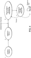
Fig. 4 is a block diagram showing the user steps in conjunction with the three-dimensional printer disclosed herein. -
Fig. 5 is a perspective view of a shovel/blade embodiment for removing a printed part. -
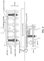
Fig. 6 is a cross-sectional view of an apparatus using pins to urge a part away from the printing surface. -
Fig. 7 is a schematic illustration of an apparatus using air pressure delivered from beneath the printing surface to release a printed part. -
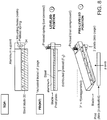
Fig. 8 constitutes views of a cantilevered blade in one embodiment of the invention. -
Fig. 9 is a perspective view of an aluminum support for receiving a hardened steel sheet to serve as a blade for use in the invention. -
Fig. 10 is a perspective view of an embodiment of the invention using a threaded rod or a lead screw to move the blade for part removal. -
Fig. 11 is a schematic illustration showing a blade supported on both sides of the printing surface. -
Fig. 12 is a schematic illustration of an electromagnet used to vibrate the printing surface for part removal. -
Fig. 13 is a schematic illustration of structure to vibrate a blade to facilitate part removal. -
Fig. 14 is a schematic illustration of the use of compressed air to remove a released part. -
Fig. 15 is a schematic illustration of a barrier brush used to receive a released part. -
Fig. 16 constitutes views of a blade mounted spring-pivot for removing a part. -
Fig. 17 is another embodiment of a flexible barrier used to remove a part. -
Fig. 18 shows a pivoting barrier with a fixed brush. -
Fig. 19 is a perspective view of a pivot barrier for use in conjunction with the invention disclosed herein. -
Fig. 20 is a cross-sectioned view of the underside of the print plate with grooves for kinematically coupling to a support structure. - With reference now to
Fig. 3 , an embodiment of the invention includes apart removal blade 20 which can be moved to release a printedpart 22. Acamera 24 is provided for assessing a part during and after it has been printed. The present invention also includes anonboard printer host 26 that is connected to a Wi-Fi network. Software for repairing and slicing 3-D models is stored in the cloud as opposed to a computer tethered to a printer as in prior art systems. An automated queue is provided to dictate the next part that the printer will print. - With reference now to
Fig. 4 , the system disclosed herein requires merely three user steps as opposed to the six steps discussed above with respect to prior art 3-D printers. In the present system, after content creation, a 3-D model is uploaded to the system. After an administrator approval (optional), the part is automatically repaired and sliced (machine code is generated from the 3-D model) with automatically selected slicing settings (based on two user inputs for speed versus quality and speed versus strength) in the cloud, then automatically loaded onto an automated queue for a particular printer. When the printer has reached that part on the queue, the g-code (machine code) is automatically loaded into the printer's local host program (typically on a local micro-computer), and streamed to the printer's microprocessor. As the printing process proceeds, thecamera 24 monitors each 2-D layer using automated computer vision to ensure that the part is printing correctly. If the part fails at any layer, the part is automatically removed and reprinted (re-slicing with different setting occurs before re-printing if the artificial intelligence software deems it necessary). The finished part (quality inspected again by the computer vision subsystem) is removed and ready for pickup. The printer then moves on to the next part on the queue. In total, there are strictly three user steps: content creation, 3-D model upload, and finished part pickup. - With reference now to
Fig. 5 , an embodiment of the part removal system is illustrated. Ablade 20 is arranged for motion across theprint plate 12 using apneumatic piston 22 to move the plate under the motive force of compressed air controlled by asolenoid valve 24. It will be understood that the motive force moving theblade 20 is adjusted to remove a part without damaging the part. - Another embodiment of the invention is illustrated in
Fig. 8 . In this embodiment, theblade 20 is cantilevered at a compliant joint 34 on one side of the unit. Theblade 20 is leveled on the printing surface and moves across the printing surface to release a part. As shown inFig. 9 , it is preferred that theblade 20 have a substrate such as aluminum to which is attached ahardened steel sheet 36 to provide the part lifting capability. -
Fig. 10 illustrates an embodiment in which a threaded rod orlead screw 38 causes theblade 20 to traverse theprinting surface 12 to engage and then remove a printed part. As shown inFig. 11 , it is contemplated that theblade 20 may be supported on both sides byguides - In another embodiment, as shown in
Fig. 13 , theblade 20 itself is caused to vibrate. Amotor 46 with a non-concentric weight may be provided to cause theblade 20 to vibrate. - After parts have been released as discussed above, compressed air may be used to remove a part from the
printing surface 12 as shown inFig. 14 . -
Fig. 15 illustrates a fixedbrush 48 that impedes movement of a part.Figs. 16 and17 show additional embodiments of arrangements for removing a part that has already been released from the surface.Fig. 18 is a perspective view showing the fixed barrier.Fig. 19 shows a pivoting barrier. -
Fig. 20 is a cross-sectional view of the underside of theprinting surface 12 in one embodiment.Grooves 40 are adapted to mate with protrusions extending from the printer's support so thatplate 12 will be level with respect to the support structure. The arrangement forms a kinematic coupling as is well-known to those of ordinary skill in the art. The arrangement of thegrooves 40 shown inFig. 20 allows theplate 12 to be positioned at a selected rotational orientation. It is preferred that once in place, theplate 12 be preloaded by, for example, a magnet or a spring to secure theplate 12 in the coupled position. - The present invention provides automated part removal solutions that solve the printing and removal disadvantages discussed above in conjunction with the prior art. The present invention discloses structures and methods that provide automated part removal at a much lower cost.
Claims (15)
- Three-dimensional printing system comprising:a printing surface (12) on which a part (22) is made;a printing device supported for controlled movement with respect to the printing surface (12) to print the part (22) on the printing surface (12); anda blade (20) supported for motion across the printing surface (12) to release the part (22) from the printing surface (12),wherein the blade (20) is cantilevered from a support on one side of the printing surface (12) or wherein the blade (20) is supported on both sides of the printing surface (12).
- The printing system of claim 1 further including a solenoid-controlled pneumatic piston (22) to move the blade (20).
- The printing system of claim 1 wherein the blade (20) is cantilevered from a support on one side of the printing surface (12).
- The printing system of claim 1 wherein in the case in which the blade (20) is cantilevered from a support on one side of the printing surface (12), the support forms a compliant joint (34).
- The printing system of claim 1 wherein the blade (20) has a hardened steel portion (36) that engages the part (22).
- The printing system of claim 1 further includinga) a lead screw (38) to move the blade (20); orb) a drive pulley driving a belt to move the blade (20) to remove the printed part (22); orc) a rack and pinion arrangement to move the blade (20); ord) means to cause the blade (20) to vibrate.
- The printing system of claim 1 further including a helper device to remove the released part (22), wherein the helper device is preferably a compressed air jet.
- The printing system of claims 1 further including a fixed barrier to restrain a released part (22).
- The printing system of claim 1 further including a torqued pivoting barrier attached to the blade (20).
- The printing system of claim 1 further including an elastic band mounted on the blade (20) to remove a released part (22).
- The printing system of claim 1 further including a computer vision system including at least one camera (24) to detect successful part (22) removal.
- The printing system of claim 1 wherein the printing surface (12) is kinematically coupled to a support structure for rapid and precise leveling of the printing surface (12).
- The printing system of claim 12 further including structure to preload the printing surface (12) with respect to the support structure.
- The printing system of claim 13 wherein the preload structure includes a magnet.
- The printing system of claim 14 wherein the support structure includes a plurality of protrusions extending from the support structure allowing the printing surface (12) to assume an approximately level position at a selected rotational orientation.
Priority Applications (1)
| Application Number | Priority Date | Filing Date | Title |
|---|---|---|---|
| EP18172343.8A EP3392026A1 (en) | 2013-02-01 | 2014-01-31 | Automated three-dimensional printer part removal |
Applications Claiming Priority (3)
| Application Number | Priority Date | Filing Date | Title |
|---|---|---|---|
| US201361759686P | 2013-02-01 | 2013-02-01 | |
| US14/157,027 US9289946B2 (en) | 2013-02-01 | 2014-01-16 | Automated three-dimensional printer part removal |
| PCT/US2014/014078 WO2014121032A1 (en) | 2013-02-01 | 2014-01-31 | Automated three-dimensional printer part removal |
Related Child Applications (2)
| Application Number | Title | Priority Date | Filing Date |
|---|---|---|---|
| EP18172343.8A Division EP3392026A1 (en) | 2013-02-01 | 2014-01-31 | Automated three-dimensional printer part removal |
| EP18172343.8A Division-Into EP3392026A1 (en) | 2013-02-01 | 2014-01-31 | Automated three-dimensional printer part removal |
Publications (2)
| Publication Number | Publication Date |
|---|---|
| EP2951004A1 EP2951004A1 (en) | 2015-12-09 |
| EP2951004B1 true EP2951004B1 (en) | 2018-11-28 |
Family
ID=51259407
Family Applications (2)
| Application Number | Title | Priority Date | Filing Date |
|---|---|---|---|
| EP14707000.7A Active EP2951004B1 (en) | 2013-02-01 | 2014-01-31 | Automated three-dimensional printer part removal |
| EP18172343.8A Withdrawn EP3392026A1 (en) | 2013-02-01 | 2014-01-31 | Automated three-dimensional printer part removal |
Family Applications After (1)
| Application Number | Title | Priority Date | Filing Date |
|---|---|---|---|
| EP18172343.8A Withdrawn EP3392026A1 (en) | 2013-02-01 | 2014-01-31 | Automated three-dimensional printer part removal |
Country Status (9)
| Country | Link |
|---|---|
| US (2) | US9289946B2 (en) |
| EP (2) | EP2951004B1 (en) |
| JP (3) | JP6215964B2 (en) |
| CN (2) | CN105026131B (en) |
| AU (1) | AU2014212279B2 (en) |
| CA (2) | CA2899590C (en) |
| ES (1) | ES2704676T3 (en) |
| MX (1) | MX361232B (en) |
| WO (1) | WO2014121032A1 (en) |
Families Citing this family (90)
| Publication number | Priority date | Publication date | Assignee | Title |
|---|---|---|---|---|
| TWI548539B (en) * | 2013-12-12 | 2016-09-11 | 三緯國際立體列印科技股份有限公司 | Three dimensional printing apparatus |
| CA2939270A1 (en) * | 2014-02-11 | 2015-08-20 | Structur3D Printing Incorporated | Multi-material extruder and extrusion method for three-dimensional (3d) printing |
| GB2546016B (en) | 2014-06-20 | 2018-11-28 | Velo3D Inc | Apparatuses, systems and methods for three-dimensional printing |
| US10668709B2 (en) * | 2014-08-12 | 2020-06-02 | Carbon, Inc. | Three-dimensional printing using carriers with release mechanisms |
| US9821518B2 (en) | 2014-08-19 | 2017-11-21 | Daniel A. Bloom | Precision platform assembly for three-dimensional printer |
| US20170259507A1 (en) * | 2014-12-01 | 2017-09-14 | Sabic Global Technologies B.V. | Additive manufacturing process automation systems and methods |
| US9782964B2 (en) * | 2015-04-02 | 2017-10-10 | Xerox Corporation | System and method for removing three-dimensional printed parts from a platen using inductive heating and gravity |
| US9937669B2 (en) | 2015-04-02 | 2018-04-10 | Xerox Corporation | Three-dimensional printed part removal using a bimetallic platen |
| US9884449B2 (en) * | 2015-04-02 | 2018-02-06 | Xerox Corporation | Three-dimensional printed part removal using an interlaced platen |
| US10814551B2 (en) * | 2015-04-02 | 2020-10-27 | Xerox Corporation | Three-dimensional printed part removal using an elastomer sheet |
| US10906244B2 (en) * | 2015-04-02 | 2021-02-02 | Xerox Corporation | Ultrasonic removal methods of three-dimensionally printed parts |
| US9381701B1 (en) | 2015-04-02 | 2016-07-05 | Xerox Corporation | Printer and method for releasing three-dimensionally printed parts from a platen using actuators |
| US20180169942A1 (en) * | 2015-05-19 | 2018-06-21 | Addifab Aps | Apparatus and method for release of additively manufactured products and build platform |
| US20180257302A1 (en) * | 2015-07-27 | 2018-09-13 | Agency For Science, Technology And Research | A multi-modal printing system and method of operating the same |
| US9916177B2 (en) * | 2015-08-19 | 2018-03-13 | International Business Machines Corporation | Predictive workload scheduling with integrated analytics |
| US11691341B2 (en) | 2015-10-30 | 2023-07-04 | Seurat Technologies, Inc. | Part manipulation using printed manipulation points |
| JP2018535121A (en) | 2015-11-06 | 2018-11-29 | ヴェロ・スリー・ディー・インコーポレイテッド | Proficient 3D printing |
| CN106738856A (en) * | 2015-11-17 | 2017-05-31 | 亚德利塑胶工厂股份有限公司 | 3D print job platform material returned mechanism |
| US10207454B2 (en) | 2015-12-10 | 2019-02-19 | Velo3D, Inc. | Systems for three-dimensional printing |
| EP3390014A4 (en) * | 2015-12-18 | 2019-12-18 | Aurora Labs Limited | 3D PRINTING METHOD AND APPARATUS |
| US20170239891A1 (en) | 2016-02-18 | 2017-08-24 | Velo3D, Inc. | Accurate three-dimensional printing |
| FR3052380B1 (en) * | 2016-06-14 | 2018-11-02 | Universite De Limoges | PROCESS AND MACHINE FOR THE PRODUCTION OF WORKPIECES BY THE TECHNIQUE OF PASSIVE ADDITIVE PROCESSES |
| US11691343B2 (en) | 2016-06-29 | 2023-07-04 | Velo3D, Inc. | Three-dimensional printing and three-dimensional printers |
| WO2018005439A1 (en) | 2016-06-29 | 2018-01-04 | Velo3D, Inc. | Three-dimensional printing and three-dimensional printers |
| JP6809858B2 (en) * | 2016-09-30 | 2021-01-06 | 株式会社Screenホールディングス | Three-dimensional modeling method |
| US20180095450A1 (en) | 2016-09-30 | 2018-04-05 | Velo3D, Inc. | Three-dimensional objects and their formation |
| EP3529059A4 (en) | 2016-10-21 | 2020-06-03 | Mosaic Manufacturing Ltd. | ASSEMBLY ELEMENT, ASSEMBLY METHODS, AND ASSOCIATED SYSTEMS FOR ADDITIVE MANUFACTURE |
| US10710302B2 (en) * | 2016-11-02 | 2020-07-14 | R3 Printing, Inc. | System and method for automated successive three-dimensional printing |
| US11660819B2 (en) | 2016-11-02 | 2023-05-30 | R3 Printing, Inc. | System and method for automated successive three-dimensional printing |
| US10661341B2 (en) | 2016-11-07 | 2020-05-26 | Velo3D, Inc. | Gas flow in three-dimensional printing |
| CN120080549A (en) * | 2016-12-15 | 2025-06-03 | 上海普利生三维科技有限公司 | Photocuring 3D printing device, method and system |
| CN108215172B (en) * | 2016-12-15 | 2022-02-15 | 上海普利生机电科技有限公司 | Three-dimensional printer |
| US10456984B2 (en) * | 2016-12-16 | 2019-10-29 | Massachusetts Institute Of Technology | Adaptive material deposition for additive manufacturing |
| US20180186080A1 (en) * | 2017-01-05 | 2018-07-05 | Velo3D, Inc. | Optics in three-dimensional printing |
| US11472105B2 (en) * | 2017-01-09 | 2022-10-18 | International Business Machines Corporation | Methods and systems for 3D printing with modifiable support |
| WO2018160807A1 (en) | 2017-03-02 | 2018-09-07 | Velo3D, Inc. | Three-dimensional printing of three dimensional objects |
| CN106863804A (en) * | 2017-03-09 | 2017-06-20 | 福建省速卖通电子商务有限公司 | A kind of 3D printing supporting station with anti-sticking function |
| US10449696B2 (en) | 2017-03-28 | 2019-10-22 | Velo3D, Inc. | Material manipulation in three-dimensional printing |
| JP7174432B2 (en) | 2017-05-16 | 2022-11-17 | 南京三迭▲紀▼医▲藥▼科技有限公司 | 3D printing device and method |
| US10974474B2 (en) * | 2017-06-12 | 2021-04-13 | General Electric Company | Applicator repair for additive manufacturing system |
| CN107175828A (en) * | 2017-07-21 | 2017-09-19 | 芜湖智享三维打印服务有限公司 | A kind of 3D printer that function is quickly removed with finished product |
| US10933587B2 (en) * | 2017-10-06 | 2021-03-02 | International Business Machines Corporation | Removing a printed item from a printer |
| DE102017124177A1 (en) | 2017-10-17 | 2019-04-18 | Trumpf Laser- Und Systemtechnik Gmbh | Tool change in generative production |
| CN107901407B (en) * | 2017-11-27 | 2021-12-07 | 庄小霞 | Three-dimensional printer and printing method thereof |
| US10272525B1 (en) | 2017-12-27 | 2019-04-30 | Velo3D, Inc. | Three-dimensional printing systems and methods of their use |
| US10201503B1 (en) | 2018-01-09 | 2019-02-12 | Triastek, Inc. | Precision pharmaceutical 3D printing device |
| WO2019245847A1 (en) * | 2018-06-22 | 2019-12-26 | 3D Systems, Inc. | Method of verifying integrity of a post-process removal of support material |
| EP3608084A1 (en) * | 2018-08-08 | 2020-02-12 | Concept Laser GmbH | Separating device |
| US20200061871A1 (en) * | 2018-08-21 | 2020-02-27 | Cincinnati Incorporated | Systems and apparatus for additive manufacturing |
| CN109228309B (en) * | 2018-09-27 | 2020-02-18 | 保靖锐恩电子有限责任公司 | A shaping platform for 3D printer |
| ES2760148A1 (en) * | 2018-11-12 | 2020-05-13 | Triditive S L | AUTOMATED MACHINE AND ADDITIVE MANUFACTURING SYSTEM (Machine-translation by Google Translate, not legally binding) |
| CN109501246B (en) * | 2018-12-26 | 2020-12-08 | 林海 | 3D printing apparatus is used in casting |
| JP7326458B2 (en) * | 2019-02-14 | 2023-08-15 | ラピッド シェイプ ゲーエムベーハー | Apparatus for manufacturing three-dimensional objects |
| WO2020198881A1 (en) * | 2019-04-04 | 2020-10-08 | Pektech Holdings Inc. | Automated part removal for additive manufacturing |
| JP7314598B2 (en) * | 2019-04-22 | 2023-07-26 | セイコーエプソン株式会社 | Three-dimensional modeling apparatus and method for manufacturing three-dimensional model |
| JP7267462B2 (en) | 2019-05-23 | 2023-05-01 | ゼネラル・エレクトリック・カンパニイ | Object formation method |
| US12076918B2 (en) | 2019-05-23 | 2024-09-03 | General Electric Company | Additive manufacturing apparatuses and methods for using the same |
| WO2020237142A1 (en) * | 2019-05-23 | 2020-11-26 | General Electric Company | Additive manufacturing recoat assemblies including a vacuum and methods for using the same |
| EP3972761A2 (en) | 2019-05-23 | 2022-03-30 | General Electric Company | Cleaning fluids for use in additive manufacturing apparatuses and methods for monitoring status and performance of the same |
| US12280596B2 (en) | 2019-05-23 | 2025-04-22 | General Electric Company | Cleaning systems for additive manufacturing apparatuses and methods for using the same |
| EP3972818A1 (en) | 2019-05-23 | 2022-03-30 | General Electric Company | Additive manufacturing recoat assemblies including sensors and methods for using the same |
| CN114126844A (en) | 2019-05-23 | 2022-03-01 | 通用电气公司 | Actuator assembly for additive manufacturing apparatus and method of using same |
| WO2020237118A2 (en) | 2019-05-23 | 2020-11-26 | General Electric Company | Wiper arrays for use in additive manufacturing apparatuses |
| US12233643B2 (en) | 2019-05-23 | 2025-02-25 | General Electric Company | Printing assemblies and methods for using the same |
| US12042988B2 (en) | 2019-05-23 | 2024-07-23 | General Electric Company | Additive manufacturing apparatuses and methods |
| US12358227B2 (en) | 2019-05-23 | 2025-07-15 | General Electric Company | Fluid management and circulation systems for use in additive manufacturing apparatuses |
| CA3148849A1 (en) | 2019-07-26 | 2021-02-04 | Velo3D, Inc. | Quality assurance in formation of three-dimensional objects |
| RU195094U1 (en) * | 2019-08-07 | 2020-01-15 | Федеральное государственное бюджетное образовательное учреждение высшего образования "Волгоградский государственный технический университет" (ВолгГТУ) | Device for automatically removing and removing printed products from a 3D printer camera |
| US12384112B2 (en) | 2019-08-20 | 2025-08-12 | Triastek, Inc. | High-throughput and high-precision pharmaceutical additive manufacturing system |
| US11269312B2 (en) | 2019-09-06 | 2022-03-08 | International Business Machines Corporation | Three dimensional printing vehicle-based auto-correction in a structure |
| AT523221B1 (en) | 2019-11-15 | 2023-01-15 | Genera Printer Gmbh | processing device |
| WO2021151047A1 (en) * | 2020-01-23 | 2021-07-29 | Impossible Objects, Inc. | Camera-based monitoring system for 3-dimensional printing |
| US12168538B2 (en) * | 2020-02-17 | 2024-12-17 | Triastek Inc. | Continuous unloading and packaging system of pharmaceutical additive manufacturing |
| EP3892446A1 (en) * | 2020-04-08 | 2021-10-13 | DENTSPLY SIRONA Inc. | Building plate assembly for use in an additive manufacturing apparatus |
| WO2021221900A1 (en) * | 2020-04-30 | 2021-11-04 | Carbon, Inc. | Film remover apparatus for additive manufacturing build platforms and related methods |
| CN111633981B (en) * | 2020-05-27 | 2022-04-15 | 芜湖职业技术学院 | A high-efficiency powder-spreading 3D printer |
| EP4178783A4 (en) | 2020-07-10 | 2024-09-25 | Triastek, Inc. | HIGH-PRECISION ADDITIVE MANUFACTURING DEVICE AND HIGH-THROUGHPUT ADDITIVE MANUFACTURING SYSTEM |
| CN112276117A (en) * | 2020-10-12 | 2021-01-29 | 安徽哈特三维科技有限公司 | Metal powder removing device of alloy type 3D printer |
| US12162074B2 (en) | 2020-11-25 | 2024-12-10 | Lawrence Livermore National Security, Llc | System and method for large-area pulsed laser melting of metallic powder in a laser powder bed fusion application |
| CN112743847B (en) * | 2020-11-30 | 2023-08-29 | 安徽工程大学 | A spatula for separating printed models of a 3D printer |
| CN113561489A (en) * | 2021-07-29 | 2021-10-29 | 深圳市创想三帝科技有限公司 | Shedder and 3D printer |
| JP7773560B2 (en) * | 2021-10-19 | 2025-11-19 | 株式会社Fuji | Three-dimensional modeling device and pallet transfer method |
| RU209858U1 (en) * | 2021-10-22 | 2022-03-23 | Общество с ограниченной ответственностью "СКАНИ" | 3D PRINTING TABLE DEVICE WITH AUTOMATIC PART REMOVAL CONVEYOR SYSTEM |
| US20230256676A1 (en) * | 2022-02-15 | 2023-08-17 | Peter Liquan Zhou | Apparatus and Method for Three-Dimensional Printing without Human Intervention |
| US11829671B2 (en) * | 2022-03-17 | 2023-11-28 | Xerox Corporation | Transfer of print queues via machine readable codes |
| IT202200024153A1 (en) * | 2022-11-24 | 2024-05-24 | Kentstrapper S R L | PRINT QUEUE MANAGEMENT AND AUTOMATIC PART REMOVAL SYSTEM FOR A 3D PRINTER |
| TWI844289B (en) * | 2023-03-03 | 2024-06-01 | 示昌智造有限公司 | Printing and cutting machine structure |
| CN117549560B (en) * | 2024-01-11 | 2024-04-02 | 西南石油大学 | A 3D printer stripping device |
| US12358221B1 (en) | 2024-03-25 | 2025-07-15 | King Saud University | Three-dimensional (3D) printer having a variously configurable printing platform assembly |
| CN118752771A (en) * | 2024-07-12 | 2024-10-11 | 江苏申久(集团)有限公司 | Composite fiber extrusion device |
Family Cites Families (46)
| Publication number | Priority date | Publication date | Assignee | Title |
|---|---|---|---|---|
| US4491559A (en) * | 1979-12-31 | 1985-01-01 | Kennametal Inc. | Flowable composition adapted for sintering and method of making |
| US4929073A (en) * | 1984-10-24 | 1990-05-29 | Hughes Aircraft Company | Kinematic mount |
| US5204055A (en) * | 1989-12-08 | 1993-04-20 | Massachusetts Institute Of Technology | Three-dimensional printing techniques |
| DE19511772C2 (en) * | 1995-03-30 | 1997-09-04 | Eos Electro Optical Syst | Device and method for producing a three-dimensional object |
| US6065898A (en) * | 1995-08-07 | 2000-05-23 | The Regents Of The University Of California | Three tooth kinematic coupling |
| US5678944A (en) * | 1995-12-07 | 1997-10-21 | Aesop, Inc. | Flexural mount kinematic couplings and method |
| US5730817A (en) * | 1996-04-22 | 1998-03-24 | Helisys, Inc. | Laminated object manufacturing system |
| US5748827A (en) * | 1996-10-23 | 1998-05-05 | University Of Washington | Two-stage kinematic mount |
| US20010014409A1 (en) * | 1997-04-04 | 2001-08-16 | Cohen Adam L. | Article, method, and apparatus for electrochemical fabrication |
| US6072569A (en) * | 1998-06-09 | 2000-06-06 | Eastman Kodak Company | Apparatus and a method for measurement of wedge in optical components |
| DE19937770C2 (en) * | 1999-08-10 | 2002-01-03 | Bayer Ag | Process for the production of three-dimensional or flat structures |
| US6325351B1 (en) * | 2000-01-05 | 2001-12-04 | The Regents Of The University Of California | Highly damped kinematic coupling for precision instruments |
| JP2001277367A (en) * | 2000-03-30 | 2001-10-09 | Sanyo Electric Co Ltd | Stereolithography device and stereolithography production method |
| JP2002178412A (en) * | 2000-12-14 | 2002-06-26 | Sanyo Electric Co Ltd | Stereolithography device and stereolithography production method |
| JP2002337242A (en) * | 2001-05-17 | 2002-11-27 | Kawakami Sangyo Co Ltd | Product transmission system |
| US6729589B2 (en) * | 2002-10-07 | 2004-05-04 | Gizmonics, Inc. | Kinematic mount |
| KR100519051B1 (en) * | 2003-07-11 | 2005-10-06 | 한국과학기술원 | 3-dimensional shape-process apparatus using non-contact heating tool and method thereof |
| US7127309B2 (en) * | 2004-02-10 | 2006-10-24 | Stratasys, Inc. | Modeling apparatus with tray substrate |
| JP2005231333A (en) * | 2004-02-17 | 2005-09-02 | Chubu Nippon Kogyo Kk | Modeling base of stereolithography equipment by regulated liquid level method |
| US8119053B1 (en) * | 2004-03-18 | 2012-02-21 | 3D Systems, Inc. | Apparatus for three dimensional printing using imaged layers |
| US7790096B2 (en) * | 2005-03-31 | 2010-09-07 | 3D Systems, Inc. | Thermal management system for a removable build chamber for use with a laser sintering system |
| EP1759791A1 (en) * | 2005-09-05 | 2007-03-07 | Nederlandse Organisatie voor toegepast- natuurwetenschappelijk onderzoek TNO | Apparatus and method for building a three-dimensional article |
| US7690909B2 (en) * | 2005-09-30 | 2010-04-06 | 3D Systems, Inc. | Rapid prototyping and manufacturing system and method |
| US20070126157A1 (en) | 2005-12-02 | 2007-06-07 | Z Corporation | Apparatus and methods for removing printed articles from a 3-D printer |
| WO2009102200A1 (en) * | 2008-02-14 | 2009-08-20 | Nederlandse Organistie Voor Toegepast-Natuurwetenschappelijk Onderzoek Tno | Method and system for layerwise production of a tangible object |
| US8206637B2 (en) * | 2008-10-14 | 2012-06-26 | The Boeing Company | Geometry adaptive laser sintering system |
| US8153183B2 (en) * | 2008-10-21 | 2012-04-10 | Stratasys, Inc. | Adjustable platform assembly for digital manufacturing system |
| JP5119123B2 (en) * | 2008-10-22 | 2013-01-16 | パナソニック株式会社 | Manufacturing method of three-dimensional shaped object |
| CN201470568U (en) * | 2009-08-25 | 2010-05-19 | 中国科学院上海应用物理研究所 | Automatic coating and scraping machine |
| US8282380B2 (en) | 2010-08-18 | 2012-10-09 | Makerbot Industries | Automated 3D build processes |
| US20120072006A1 (en) | 2010-09-17 | 2012-03-22 | Synerdyne Corporation | System and method for rapid fabrication of arbitrary three-dimensional objects |
| JP2013067036A (en) * | 2011-09-21 | 2013-04-18 | Keyence Corp | Three-dimensional shaping apparatus |
| US9205690B2 (en) * | 2012-03-16 | 2015-12-08 | Stratasys, Inc. | Automated calibration method for additive manufacturing system, and method of use thereof |
| US9481134B2 (en) * | 2012-06-08 | 2016-11-01 | Makerbot Industries, Llc | Build platform leveling with tactile feedback |
| US20140085620A1 (en) * | 2012-09-24 | 2014-03-27 | Maxim Lobovsky | 3d printer with self-leveling platform |
| GB201322647D0 (en) * | 2013-12-20 | 2014-02-05 | Renishaw Plc | Additive manufacturing apparatus and method |
| NL2012198C2 (en) * | 2014-02-04 | 2015-08-06 | Leapfrog B V | DEVICE FOR FORMING A WORKPIECE THROUGH 3D EXTRUSION. |
| WO2015148665A1 (en) * | 2014-03-28 | 2015-10-01 | Booker Scott | Three-dimensional printer platform leveling apparatus and method |
| US9895872B2 (en) * | 2014-07-31 | 2018-02-20 | Xyzprinting, Inc. | Three-dimensional printing apparatus |
| US9821518B2 (en) * | 2014-08-19 | 2017-11-21 | Daniel A. Bloom | Precision platform assembly for three-dimensional printer |
| EP3186065B1 (en) * | 2014-08-28 | 2021-12-15 | Incodema3d LLC | Additive manufacturing device |
| US9656424B2 (en) * | 2014-09-29 | 2017-05-23 | Xerox Corporation | System for adjusting platform height during three-dimensional printing of an object |
| US9724878B2 (en) * | 2014-10-20 | 2017-08-08 | Lenovo Enterprise Solutions (Singapore) Pte. Ltd. | Three-dimensional printer having an expandable envelope |
| KR101591938B1 (en) * | 2015-01-19 | 2016-02-04 | 숭실대학교산학협력단 | 3-d printer having dual stage |
| TWI555647B (en) * | 2015-08-10 | 2016-11-01 | 東友科技股份有限公司 | Supporting module of printing platform and three-dimensional printer using same |
| US10514678B2 (en) * | 2016-06-28 | 2019-12-24 | Robert Bosch Tool Corporation | Method for leveling a 3-D printing platform and a 3-D platform with adjustable level |
-
2014
- 2014-01-16 US US14/157,027 patent/US9289946B2/en active Active
- 2014-01-31 CN CN201480007068.0A patent/CN105026131B/en active Active
- 2014-01-31 ES ES14707000T patent/ES2704676T3/en active Active
- 2014-01-31 WO PCT/US2014/014078 patent/WO2014121032A1/en not_active Ceased
- 2014-01-31 AU AU2014212279A patent/AU2014212279B2/en active Active
- 2014-01-31 CN CN201810599439.9A patent/CN108891028A/en active Pending
- 2014-01-31 JP JP2015556158A patent/JP6215964B2/en active Active
- 2014-01-31 CA CA2899590A patent/CA2899590C/en active Active
- 2014-01-31 EP EP14707000.7A patent/EP2951004B1/en active Active
- 2014-01-31 MX MX2015009971A patent/MX361232B/en active IP Right Grant
- 2014-01-31 CA CA3014094A patent/CA3014094A1/en not_active Abandoned
- 2014-01-31 EP EP18172343.8A patent/EP3392026A1/en not_active Withdrawn
-
2016
- 2016-02-11 US US15/041,208 patent/US20160159010A1/en not_active Abandoned
-
2017
- 2017-06-13 JP JP2017115848A patent/JP6480509B2/en active Active
-
2019
- 2019-02-07 JP JP2019020275A patent/JP2019073032A/en active Pending
Non-Patent Citations (1)
| Title |
|---|
| None * |
Also Published As
| Publication number | Publication date |
|---|---|
| US9289946B2 (en) | 2016-03-22 |
| AU2014212279A1 (en) | 2015-08-20 |
| AU2014212279B2 (en) | 2017-02-16 |
| CA2899590C (en) | 2019-06-25 |
| ES2704676T3 (en) | 2019-03-19 |
| JP6215964B2 (en) | 2017-10-18 |
| CA3014094A1 (en) | 2014-08-07 |
| EP3392026A1 (en) | 2018-10-24 |
| JP2017177819A (en) | 2017-10-05 |
| CA2899590A1 (en) | 2014-08-07 |
| EP2951004A1 (en) | 2015-12-09 |
| JP2019073032A (en) | 2019-05-16 |
| US20160159010A1 (en) | 2016-06-09 |
| CN105026131A (en) | 2015-11-04 |
| JP6480509B2 (en) | 2019-03-13 |
| WO2014121032A1 (en) | 2014-08-07 |
| MX2015009971A (en) | 2015-09-29 |
| CN105026131B (en) | 2018-09-14 |
| MX361232B (en) | 2018-11-30 |
| CN108891028A (en) | 2018-11-27 |
| US20140220168A1 (en) | 2014-08-07 |
| JP2016508904A (en) | 2016-03-24 |
Similar Documents
| Publication | Publication Date | Title |
|---|---|---|
| US9289946B2 (en) | Automated three-dimensional printer part removal | |
| US9475234B2 (en) | Powder removing apparatus, molding system, and method of manufacturing molded object | |
| CN106626801B (en) | A kind of character spray printing machine | |
| US20240208153A1 (en) | Separation Control Systems and Methods for 3D Printers | |
| CN103464340B (en) | Automatic loading/unloading multilamellar baking-curing point gum machine | |
| US10814551B2 (en) | Three-dimensional printed part removal using an elastomer sheet | |
| US9884449B2 (en) | Three-dimensional printed part removal using an interlaced platen | |
| US20170368752A1 (en) | Non-contact control of layering for three-dimensional object printing | |
| WO2012012034A2 (en) | Electromagnetic crawler assembly system | |
| US20190030900A1 (en) | Three-dimensional printing device | |
| JP7455971B2 (en) | Equipment for processing objects produced by additive manufacturing | |
| US9352572B2 (en) | System for detecting inoperative inkjets in three-dimensional object printing using an optical sensor and movable test substrates | |
| JP6950085B2 (en) | Mounting work machine and confirmation method | |
| JP6141727B2 (en) | Inkjet printer | |
| JP6141726B2 (en) | Inkjet printer | |
| CN120461833A (en) | Finished product unloading device for 3D printer and method of use | |
| CN110976763B (en) | A side-mounted machine arm type 3D sand printing equipment | |
| CN103006333A (en) | Pelvis impact test device | |
| CN121515468A (en) | 3D printing equipment and its part retrieval system | |
| CN110681828A (en) | Automatic printing test paper conveying device and test paper conveying method | |
| JPWO2016093032A1 (en) | Carriage lifting mechanism and ink jet recording apparatus |
Legal Events
| Date | Code | Title | Description |
|---|---|---|---|
| PUAI | Public reference made under article 153(3) epc to a published international application that has entered the european phase |
Free format text: ORIGINAL CODE: 0009012 |
|
| 17P | Request for examination filed |
Effective date: 20150730 |
|
| AK | Designated contracting states |
Kind code of ref document: A1 Designated state(s): AL AT BE BG CH CY CZ DE DK EE ES FI FR GB GR HR HU IE IS IT LI LT LU LV MC MK MT NL NO PL PT RO RS SE SI SK SM TR |
|
| AX | Request for extension of the european patent |
Extension state: BA ME |
|
| RIN1 | Information on inventor provided before grant (corrected) |
Inventor name: PEREZ, ALFONSO, ALEXANDER Inventor name: HAID, CHRISTOPHER, MICHAEL Inventor name: PENA DOLL, MATEO Inventor name: PIEPER, FORREST, W. |
|
| RIN1 | Information on inventor provided before grant (corrected) |
Inventor name: PIEPER, FORREST, W. Inventor name: PENA DOLL, MATEO Inventor name: HAID, CHRISTOPHER, MICHAEL Inventor name: PEREZ, ALFONSO, ALEXANDER |
|
| DAX | Request for extension of the european patent (deleted) | ||
| STAA | Information on the status of an ep patent application or granted ep patent |
Free format text: STATUS: EXAMINATION IS IN PROGRESS |
|
| RIC1 | Information provided on ipc code assigned before grant |
Ipc: B29C 64/379 20170101ALI20171207BHEP Ipc: B29C 64/236 20170101ALI20171207BHEP Ipc: B29C 64/214 20170101ALI20171207BHEP Ipc: B29C 37/00 20060101AFI20171207BHEP |
|
| 17Q | First examination report despatched |
Effective date: 20171220 |
|
| REG | Reference to a national code |
Ref country code: DE Ref legal event code: R079 Ref document number: 602014036875 Country of ref document: DE Free format text: PREVIOUS MAIN CLASS: B29C0067000000 Ipc: B29C0064379000 |
|
| GRAP | Despatch of communication of intention to grant a patent |
Free format text: ORIGINAL CODE: EPIDOSNIGR1 |
|
| STAA | Information on the status of an ep patent application or granted ep patent |
Free format text: STATUS: GRANT OF PATENT IS INTENDED |
|
| RIC1 | Information provided on ipc code assigned before grant |
Ipc: B29C 64/236 20170101ALI20180601BHEP Ipc: B29C 64/379 20170101AFI20180601BHEP Ipc: B29C 64/214 20170101ALI20180601BHEP |
|
| INTG | Intention to grant announced |
Effective date: 20180618 |
|
| GRAS | Grant fee paid |
Free format text: ORIGINAL CODE: EPIDOSNIGR3 |
|
| GRAA | (expected) grant |
Free format text: ORIGINAL CODE: 0009210 |
|
| STAA | Information on the status of an ep patent application or granted ep patent |
Free format text: STATUS: THE PATENT HAS BEEN GRANTED |
|
| AK | Designated contracting states |
Kind code of ref document: B1 Designated state(s): AL AT BE BG CH CY CZ DE DK EE ES FI FR GB GR HR HU IE IS IT LI LT LU LV MC MK MT NL NO PL PT RO RS SE SI SK SM TR |
|
| REG | Reference to a national code |
Ref country code: CH Ref legal event code: EP |
|
| REG | Reference to a national code |
Ref country code: AT Ref legal event code: REF Ref document number: 1069710 Country of ref document: AT Kind code of ref document: T Effective date: 20181215 |
|
| REG | Reference to a national code |
Ref country code: DE Ref legal event code: R096 Ref document number: 602014036875 Country of ref document: DE |
|
| REG | Reference to a national code |
Ref country code: IE Ref legal event code: FG4D |
|
| REG | Reference to a national code |
Ref country code: CH Ref legal event code: PK Free format text: BERICHTIGUNGEN |
|
| RIC2 | Information provided on ipc code assigned after grant |
Ipc: B29C 64/214 20170101ALI20180601BHEP Ipc: B29C 64/379 20170101AFI20180601BHEP Ipc: B29C 64/236 20170101ALI20180601BHEP |
|
| REG | Reference to a national code |
Ref country code: ES Ref legal event code: FG2A Ref document number: 2704676 Country of ref document: ES Kind code of ref document: T3 Effective date: 20190319 |
|
| REG | Reference to a national code |
Ref country code: NL Ref legal event code: MP Effective date: 20181128 |
|
| REG | Reference to a national code |
Ref country code: LT Ref legal event code: MG4D |
|
| REG | Reference to a national code |
Ref country code: AT Ref legal event code: MK05 Ref document number: 1069710 Country of ref document: AT Kind code of ref document: T Effective date: 20181128 |
|
| PG25 | Lapsed in a contracting state [announced via postgrant information from national office to epo] |
Ref country code: FI Free format text: LAPSE BECAUSE OF FAILURE TO SUBMIT A TRANSLATION OF THE DESCRIPTION OR TO PAY THE FEE WITHIN THE PRESCRIBED TIME-LIMIT Effective date: 20181128 Ref country code: LV Free format text: LAPSE BECAUSE OF FAILURE TO SUBMIT A TRANSLATION OF THE DESCRIPTION OR TO PAY THE FEE WITHIN THE PRESCRIBED TIME-LIMIT Effective date: 20181128 Ref country code: AT Free format text: LAPSE BECAUSE OF FAILURE TO SUBMIT A TRANSLATION OF THE DESCRIPTION OR TO PAY THE FEE WITHIN THE PRESCRIBED TIME-LIMIT Effective date: 20181128 Ref country code: HR Free format text: LAPSE BECAUSE OF FAILURE TO SUBMIT A TRANSLATION OF THE DESCRIPTION OR TO PAY THE FEE WITHIN THE PRESCRIBED TIME-LIMIT Effective date: 20181128 Ref country code: NO Free format text: LAPSE BECAUSE OF FAILURE TO SUBMIT A TRANSLATION OF THE DESCRIPTION OR TO PAY THE FEE WITHIN THE PRESCRIBED TIME-LIMIT Effective date: 20190228 Ref country code: BG Free format text: LAPSE BECAUSE OF FAILURE TO SUBMIT A TRANSLATION OF THE DESCRIPTION OR TO PAY THE FEE WITHIN THE PRESCRIBED TIME-LIMIT Effective date: 20190228 Ref country code: LT Free format text: LAPSE BECAUSE OF FAILURE TO SUBMIT A TRANSLATION OF THE DESCRIPTION OR TO PAY THE FEE WITHIN THE PRESCRIBED TIME-LIMIT Effective date: 20181128 Ref country code: IS Free format text: LAPSE BECAUSE OF FAILURE TO SUBMIT A TRANSLATION OF THE DESCRIPTION OR TO PAY THE FEE WITHIN THE PRESCRIBED TIME-LIMIT Effective date: 20190328 |
|
| PG25 | Lapsed in a contracting state [announced via postgrant information from national office to epo] |
Ref country code: AL Free format text: LAPSE BECAUSE OF FAILURE TO SUBMIT A TRANSLATION OF THE DESCRIPTION OR TO PAY THE FEE WITHIN THE PRESCRIBED TIME-LIMIT Effective date: 20181128 Ref country code: PT Free format text: LAPSE BECAUSE OF FAILURE TO SUBMIT A TRANSLATION OF THE DESCRIPTION OR TO PAY THE FEE WITHIN THE PRESCRIBED TIME-LIMIT Effective date: 20190328 Ref country code: GR Free format text: LAPSE BECAUSE OF FAILURE TO SUBMIT A TRANSLATION OF THE DESCRIPTION OR TO PAY THE FEE WITHIN THE PRESCRIBED TIME-LIMIT Effective date: 20190301 Ref country code: SE Free format text: LAPSE BECAUSE OF FAILURE TO SUBMIT A TRANSLATION OF THE DESCRIPTION OR TO PAY THE FEE WITHIN THE PRESCRIBED TIME-LIMIT Effective date: 20181128 Ref country code: RS Free format text: LAPSE BECAUSE OF FAILURE TO SUBMIT A TRANSLATION OF THE DESCRIPTION OR TO PAY THE FEE WITHIN THE PRESCRIBED TIME-LIMIT Effective date: 20181128 |
|
| PG25 | Lapsed in a contracting state [announced via postgrant information from national office to epo] |
Ref country code: NL Free format text: LAPSE BECAUSE OF FAILURE TO SUBMIT A TRANSLATION OF THE DESCRIPTION OR TO PAY THE FEE WITHIN THE PRESCRIBED TIME-LIMIT Effective date: 20181128 |
|
| PG25 | Lapsed in a contracting state [announced via postgrant information from national office to epo] |
Ref country code: CZ Free format text: LAPSE BECAUSE OF FAILURE TO SUBMIT A TRANSLATION OF THE DESCRIPTION OR TO PAY THE FEE WITHIN THE PRESCRIBED TIME-LIMIT Effective date: 20181128 Ref country code: DK Free format text: LAPSE BECAUSE OF FAILURE TO SUBMIT A TRANSLATION OF THE DESCRIPTION OR TO PAY THE FEE WITHIN THE PRESCRIBED TIME-LIMIT Effective date: 20181128 Ref country code: PL Free format text: LAPSE BECAUSE OF FAILURE TO SUBMIT A TRANSLATION OF THE DESCRIPTION OR TO PAY THE FEE WITHIN THE PRESCRIBED TIME-LIMIT Effective date: 20181128 |
|
| REG | Reference to a national code |
Ref country code: DE Ref legal event code: R097 Ref document number: 602014036875 Country of ref document: DE |
|
| PG25 | Lapsed in a contracting state [announced via postgrant information from national office to epo] |
Ref country code: EE Free format text: LAPSE BECAUSE OF FAILURE TO SUBMIT A TRANSLATION OF THE DESCRIPTION OR TO PAY THE FEE WITHIN THE PRESCRIBED TIME-LIMIT Effective date: 20181128 Ref country code: SM Free format text: LAPSE BECAUSE OF FAILURE TO SUBMIT A TRANSLATION OF THE DESCRIPTION OR TO PAY THE FEE WITHIN THE PRESCRIBED TIME-LIMIT Effective date: 20181128 Ref country code: SK Free format text: LAPSE BECAUSE OF FAILURE TO SUBMIT A TRANSLATION OF THE DESCRIPTION OR TO PAY THE FEE WITHIN THE PRESCRIBED TIME-LIMIT Effective date: 20181128 Ref country code: MC Free format text: LAPSE BECAUSE OF FAILURE TO SUBMIT A TRANSLATION OF THE DESCRIPTION OR TO PAY THE FEE WITHIN THE PRESCRIBED TIME-LIMIT Effective date: 20181128 Ref country code: RO Free format text: LAPSE BECAUSE OF FAILURE TO SUBMIT A TRANSLATION OF THE DESCRIPTION OR TO PAY THE FEE WITHIN THE PRESCRIBED TIME-LIMIT Effective date: 20181128 |
|
| REG | Reference to a national code |
Ref country code: CH Ref legal event code: PL |
|
| PG25 | Lapsed in a contracting state [announced via postgrant information from national office to epo] |
Ref country code: LU Free format text: LAPSE BECAUSE OF NON-PAYMENT OF DUE FEES Effective date: 20190131 |
|
| PLBE | No opposition filed within time limit |
Free format text: ORIGINAL CODE: 0009261 |
|
| STAA | Information on the status of an ep patent application or granted ep patent |
Free format text: STATUS: NO OPPOSITION FILED WITHIN TIME LIMIT |
|
| REG | Reference to a national code |
Ref country code: BE Ref legal event code: MM Effective date: 20190131 |
|
| REG | Reference to a national code |
Ref country code: IE Ref legal event code: MM4A |
|
| PG25 | Lapsed in a contracting state [announced via postgrant information from national office to epo] |
Ref country code: SI Free format text: LAPSE BECAUSE OF FAILURE TO SUBMIT A TRANSLATION OF THE DESCRIPTION OR TO PAY THE FEE WITHIN THE PRESCRIBED TIME-LIMIT Effective date: 20181128 |
|
| 26N | No opposition filed |
Effective date: 20190829 |
|
| PG25 | Lapsed in a contracting state [announced via postgrant information from national office to epo] |
Ref country code: BE Free format text: LAPSE BECAUSE OF NON-PAYMENT OF DUE FEES Effective date: 20190131 |
|
| PG25 | Lapsed in a contracting state [announced via postgrant information from national office to epo] |
Ref country code: CH Free format text: LAPSE BECAUSE OF NON-PAYMENT OF DUE FEES Effective date: 20190131 Ref country code: LI Free format text: LAPSE BECAUSE OF NON-PAYMENT OF DUE FEES Effective date: 20190131 |
|
| PG25 | Lapsed in a contracting state [announced via postgrant information from national office to epo] |
Ref country code: IE Free format text: LAPSE BECAUSE OF NON-PAYMENT OF DUE FEES Effective date: 20190131 |
|
| PG25 | Lapsed in a contracting state [announced via postgrant information from national office to epo] |
Ref country code: TR Free format text: LAPSE BECAUSE OF FAILURE TO SUBMIT A TRANSLATION OF THE DESCRIPTION OR TO PAY THE FEE WITHIN THE PRESCRIBED TIME-LIMIT Effective date: 20181128 |
|
| PG25 | Lapsed in a contracting state [announced via postgrant information from national office to epo] |
Ref country code: MT Free format text: LAPSE BECAUSE OF NON-PAYMENT OF DUE FEES Effective date: 20190131 |
|
| PG25 | Lapsed in a contracting state [announced via postgrant information from national office to epo] |
Ref country code: CY Free format text: LAPSE BECAUSE OF FAILURE TO SUBMIT A TRANSLATION OF THE DESCRIPTION OR TO PAY THE FEE WITHIN THE PRESCRIBED TIME-LIMIT Effective date: 20181128 |
|
| PG25 | Lapsed in a contracting state [announced via postgrant information from national office to epo] |
Ref country code: HU Free format text: LAPSE BECAUSE OF FAILURE TO SUBMIT A TRANSLATION OF THE DESCRIPTION OR TO PAY THE FEE WITHIN THE PRESCRIBED TIME-LIMIT; INVALID AB INITIO Effective date: 20140131 |
|
| PG25 | Lapsed in a contracting state [announced via postgrant information from national office to epo] |
Ref country code: MK Free format text: LAPSE BECAUSE OF FAILURE TO SUBMIT A TRANSLATION OF THE DESCRIPTION OR TO PAY THE FEE WITHIN THE PRESCRIBED TIME-LIMIT Effective date: 20181128 |
|
| P01 | Opt-out of the competence of the unified patent court (upc) registered |
Effective date: 20230528 |
|
| PGFP | Annual fee paid to national office [announced via postgrant information from national office to epo] |
Ref country code: GB Payment date: 20260127 Year of fee payment: 13 |
|
| PGFP | Annual fee paid to national office [announced via postgrant information from national office to epo] |
Ref country code: ES Payment date: 20260202 Year of fee payment: 13 |
|
| PGFP | Annual fee paid to national office [announced via postgrant information from national office to epo] |
Ref country code: DE Payment date: 20260128 Year of fee payment: 13 |
|
| PGFP | Annual fee paid to national office [announced via postgrant information from national office to epo] |
Ref country code: IT Payment date: 20260121 Year of fee payment: 13 |
|
| PGFP | Annual fee paid to national office [announced via postgrant information from national office to epo] |
Ref country code: FR Payment date: 20260126 Year of fee payment: 13 |