EP2950414A1 - Power system control system - Google Patents
Power system control system Download PDFInfo
- Publication number
- EP2950414A1 EP2950414A1 EP14742951.8A EP14742951A EP2950414A1 EP 2950414 A1 EP2950414 A1 EP 2950414A1 EP 14742951 A EP14742951 A EP 14742951A EP 2950414 A1 EP2950414 A1 EP 2950414A1
- Authority
- EP
- European Patent Office
- Prior art keywords
- section
- difference
- control
- demand
- power
- Prior art date
- Legal status (The legal status is an assumption and is not a legal conclusion. Google has not performed a legal analysis and makes no representation as to the accuracy of the status listed.)
- Withdrawn
Links
Images




Classifications
-
- G—PHYSICS
- G06—COMPUTING OR CALCULATING; COUNTING
- G06Q—INFORMATION AND COMMUNICATION TECHNOLOGY [ICT] SPECIALLY ADAPTED FOR ADMINISTRATIVE, COMMERCIAL, FINANCIAL, MANAGERIAL OR SUPERVISORY PURPOSES; SYSTEMS OR METHODS SPECIALLY ADAPTED FOR ADMINISTRATIVE, COMMERCIAL, FINANCIAL, MANAGERIAL OR SUPERVISORY PURPOSES, NOT OTHERWISE PROVIDED FOR
- G06Q10/00—Administration; Management
- G06Q10/04—Forecasting or optimisation specially adapted for administrative or management purposes, e.g. linear programming or "cutting stock problem"
-
- G—PHYSICS
- G05—CONTROLLING; REGULATING
- G05B—CONTROL OR REGULATING SYSTEMS IN GENERAL; FUNCTIONAL ELEMENTS OF SUCH SYSTEMS; MONITORING OR TESTING ARRANGEMENTS FOR SUCH SYSTEMS OR ELEMENTS
- G05B15/00—Systems controlled by a computer
-
- G—PHYSICS
- G06—COMPUTING OR CALCULATING; COUNTING
- G06Q—INFORMATION AND COMMUNICATION TECHNOLOGY [ICT] SPECIALLY ADAPTED FOR ADMINISTRATIVE, COMMERCIAL, FINANCIAL, MANAGERIAL OR SUPERVISORY PURPOSES; SYSTEMS OR METHODS SPECIALLY ADAPTED FOR ADMINISTRATIVE, COMMERCIAL, FINANCIAL, MANAGERIAL OR SUPERVISORY PURPOSES, NOT OTHERWISE PROVIDED FOR
- G06Q50/00—Information and communication technology [ICT] specially adapted for implementation of business processes of specific business sectors, e.g. utilities or tourism
- G06Q50/06—Energy or water supply
-
- H—ELECTRICITY
- H02—GENERATION; CONVERSION OR DISTRIBUTION OF ELECTRIC POWER
- H02J—ELECTRIC POWER NETWORKS; CIRCUIT ARRANGEMENTS OR SYSTEMS FOR SUPPLYING OR DISTRIBUTING ELECTRIC POWER; SYSTEMS FOR STORING ELECTRIC ENERGY
- H02J3/00—Circuit arrangements for AC mains or AC distribution networks
- H02J3/003—Load forecast, e.g. methods or systems for forecasting future load demand
-
- H—ELECTRICITY
- H02—GENERATION; CONVERSION OR DISTRIBUTION OF ELECTRIC POWER
- H02J—ELECTRIC POWER NETWORKS; CIRCUIT ARRANGEMENTS OR SYSTEMS FOR SUPPLYING OR DISTRIBUTING ELECTRIC POWER; SYSTEMS FOR STORING ELECTRIC ENERGY
- H02J3/00—Circuit arrangements for AC mains or AC distribution networks
- H02J3/28—Arrangements for balancing of the load in networks by storage of energy
- H02J3/32—Arrangements for balancing of the load in networks by storage of energy using batteries or super capacitors with converting means
-
- H—ELECTRICITY
- H02—GENERATION; CONVERSION OR DISTRIBUTION OF ELECTRIC POWER
- H02J—ELECTRIC POWER NETWORKS; CIRCUIT ARRANGEMENTS OR SYSTEMS FOR SUPPLYING OR DISTRIBUTING ELECTRIC POWER; SYSTEMS FOR STORING ELECTRIC ENERGY
- H02J3/00—Circuit arrangements for AC mains or AC distribution networks
- H02J3/38—Arrangements for feeding a single network from two or more generators or sources in parallel; Arrangements for feeding already energised networks from additional generators or sources in parallel
- H02J3/46—Controlling the sharing of generated power between the generators, sources or networks
-
- H—ELECTRICITY
- H02—GENERATION; CONVERSION OR DISTRIBUTION OF ELECTRIC POWER
- H02J—ELECTRIC POWER NETWORKS; CIRCUIT ARRANGEMENTS OR SYSTEMS FOR SUPPLYING OR DISTRIBUTING ELECTRIC POWER; SYSTEMS FOR STORING ELECTRIC ENERGY
- H02J2101/00—Supply or distribution of decentralised, dispersed or local electric power generation
- H02J2101/20—Dispersed power generation using renewable energy sources
- H02J2101/22—Solar energy
- H02J2101/24—Photovoltaics
-
- H—ELECTRICITY
- H02—GENERATION; CONVERSION OR DISTRIBUTION OF ELECTRIC POWER
- H02J—ELECTRIC POWER NETWORKS; CIRCUIT ARRANGEMENTS OR SYSTEMS FOR SUPPLYING OR DISTRIBUTING ELECTRIC POWER; SYSTEMS FOR STORING ELECTRIC ENERGY
- H02J2101/00—Supply or distribution of decentralised, dispersed or local electric power generation
- H02J2101/20—Dispersed power generation using renewable energy sources
- H02J2101/28—Wind energy
-
- H—ELECTRICITY
- H02—GENERATION; CONVERSION OR DISTRIBUTION OF ELECTRIC POWER
- H02J—ELECTRIC POWER NETWORKS; CIRCUIT ARRANGEMENTS OR SYSTEMS FOR SUPPLYING OR DISTRIBUTING ELECTRIC POWER; SYSTEMS FOR STORING ELECTRIC ENERGY
- H02J3/00—Circuit arrangements for AC mains or AC distribution networks
- H02J3/008—Circuit arrangements for power supply or distribution technologies responsive to energy trading
-
- H—ELECTRICITY
- H02—GENERATION; CONVERSION OR DISTRIBUTION OF ELECTRIC POWER
- H02J—ELECTRIC POWER NETWORKS; CIRCUIT ARRANGEMENTS OR SYSTEMS FOR SUPPLYING OR DISTRIBUTING ELECTRIC POWER; SYSTEMS FOR STORING ELECTRIC ENERGY
- H02J3/00—Circuit arrangements for AC mains or AC distribution networks
- H02J3/38—Arrangements for feeding a single network from two or more generators or sources in parallel; Arrangements for feeding already energised networks from additional generators or sources in parallel
- H02J3/381—Dispersed generators
-
- Y—GENERAL TAGGING OF NEW TECHNOLOGICAL DEVELOPMENTS; GENERAL TAGGING OF CROSS-SECTIONAL TECHNOLOGIES SPANNING OVER SEVERAL SECTIONS OF THE IPC; TECHNICAL SUBJECTS COVERED BY FORMER USPC CROSS-REFERENCE ART COLLECTIONS [XRACs] AND DIGESTS
- Y02—TECHNOLOGIES OR APPLICATIONS FOR MITIGATION OR ADAPTATION AGAINST CLIMATE CHANGE
- Y02E—REDUCTION OF GREENHOUSE GAS [GHG] EMISSIONS, RELATED TO ENERGY GENERATION, TRANSMISSION OR DISTRIBUTION
- Y02E10/00—Energy generation through renewable energy sources
- Y02E10/50—Photovoltaic [PV] energy
- Y02E10/56—Power conversion systems, e.g. maximum power point trackers
-
- Y—GENERAL TAGGING OF NEW TECHNOLOGICAL DEVELOPMENTS; GENERAL TAGGING OF CROSS-SECTIONAL TECHNOLOGIES SPANNING OVER SEVERAL SECTIONS OF THE IPC; TECHNICAL SUBJECTS COVERED BY FORMER USPC CROSS-REFERENCE ART COLLECTIONS [XRACs] AND DIGESTS
- Y02—TECHNOLOGIES OR APPLICATIONS FOR MITIGATION OR ADAPTATION AGAINST CLIMATE CHANGE
- Y02E—REDUCTION OF GREENHOUSE GAS [GHG] EMISSIONS, RELATED TO ENERGY GENERATION, TRANSMISSION OR DISTRIBUTION
- Y02E10/00—Energy generation through renewable energy sources
- Y02E10/70—Wind energy
- Y02E10/76—Power conversion electric or electronic aspects
-
- Y—GENERAL TAGGING OF NEW TECHNOLOGICAL DEVELOPMENTS; GENERAL TAGGING OF CROSS-SECTIONAL TECHNOLOGIES SPANNING OVER SEVERAL SECTIONS OF THE IPC; TECHNICAL SUBJECTS COVERED BY FORMER USPC CROSS-REFERENCE ART COLLECTIONS [XRACs] AND DIGESTS
- Y02—TECHNOLOGIES OR APPLICATIONS FOR MITIGATION OR ADAPTATION AGAINST CLIMATE CHANGE
- Y02E—REDUCTION OF GREENHOUSE GAS [GHG] EMISSIONS, RELATED TO ENERGY GENERATION, TRANSMISSION OR DISTRIBUTION
- Y02E70/00—Other energy conversion or management systems reducing GHG emissions
- Y02E70/30—Systems combining energy storage with energy generation of non-fossil origin
-
- Y—GENERAL TAGGING OF NEW TECHNOLOGICAL DEVELOPMENTS; GENERAL TAGGING OF CROSS-SECTIONAL TECHNOLOGIES SPANNING OVER SEVERAL SECTIONS OF THE IPC; TECHNICAL SUBJECTS COVERED BY FORMER USPC CROSS-REFERENCE ART COLLECTIONS [XRACs] AND DIGESTS
- Y04—INFORMATION OR COMMUNICATION TECHNOLOGIES HAVING AN IMPACT ON OTHER TECHNOLOGY AREAS
- Y04S—SYSTEMS INTEGRATING TECHNOLOGIES RELATED TO POWER NETWORK OPERATION, COMMUNICATION OR INFORMATION TECHNOLOGIES FOR IMPROVING THE ELECTRICAL POWER GENERATION, TRANSMISSION, DISTRIBUTION, MANAGEMENT OR USAGE, i.e. SMART GRIDS
- Y04S10/00—Systems supporting electrical power generation, transmission or distribution
- Y04S10/50—Systems or methods supporting the power network operation or management, involving a certain degree of interaction with the load-side end user applications
-
- Y—GENERAL TAGGING OF NEW TECHNOLOGICAL DEVELOPMENTS; GENERAL TAGGING OF CROSS-SECTIONAL TECHNOLOGIES SPANNING OVER SEVERAL SECTIONS OF THE IPC; TECHNICAL SUBJECTS COVERED BY FORMER USPC CROSS-REFERENCE ART COLLECTIONS [XRACs] AND DIGESTS
- Y04—INFORMATION OR COMMUNICATION TECHNOLOGIES HAVING AN IMPACT ON OTHER TECHNOLOGY AREAS
- Y04S—SYSTEMS INTEGRATING TECHNOLOGIES RELATED TO POWER NETWORK OPERATION, COMMUNICATION OR INFORMATION TECHNOLOGIES FOR IMPROVING THE ELECTRICAL POWER GENERATION, TRANSMISSION, DISTRIBUTION, MANAGEMENT OR USAGE, i.e. SMART GRIDS
- Y04S20/00—Management or operation of end-user stationary applications or the last stages of power distribution; Controlling, monitoring or operating thereof
-
- Y—GENERAL TAGGING OF NEW TECHNOLOGICAL DEVELOPMENTS; GENERAL TAGGING OF CROSS-SECTIONAL TECHNOLOGIES SPANNING OVER SEVERAL SECTIONS OF THE IPC; TECHNICAL SUBJECTS COVERED BY FORMER USPC CROSS-REFERENCE ART COLLECTIONS [XRACs] AND DIGESTS
- Y04—INFORMATION OR COMMUNICATION TECHNOLOGIES HAVING AN IMPACT ON OTHER TECHNOLOGY AREAS
- Y04S—SYSTEMS INTEGRATING TECHNOLOGIES RELATED TO POWER NETWORK OPERATION, COMMUNICATION OR INFORMATION TECHNOLOGIES FOR IMPROVING THE ELECTRICAL POWER GENERATION, TRANSMISSION, DISTRIBUTION, MANAGEMENT OR USAGE, i.e. SMART GRIDS
- Y04S20/00—Management or operation of end-user stationary applications or the last stages of power distribution; Controlling, monitoring or operating thereof
- Y04S20/30—Smart metering, e.g. specially adapted for remote reading
-
- Y—GENERAL TAGGING OF NEW TECHNOLOGICAL DEVELOPMENTS; GENERAL TAGGING OF CROSS-SECTIONAL TECHNOLOGIES SPANNING OVER SEVERAL SECTIONS OF THE IPC; TECHNICAL SUBJECTS COVERED BY FORMER USPC CROSS-REFERENCE ART COLLECTIONS [XRACs] AND DIGESTS
- Y04—INFORMATION OR COMMUNICATION TECHNOLOGIES HAVING AN IMPACT ON OTHER TECHNOLOGY AREAS
- Y04S—SYSTEMS INTEGRATING TECHNOLOGIES RELATED TO POWER NETWORK OPERATION, COMMUNICATION OR INFORMATION TECHNOLOGIES FOR IMPROVING THE ELECTRICAL POWER GENERATION, TRANSMISSION, DISTRIBUTION, MANAGEMENT OR USAGE, i.e. SMART GRIDS
- Y04S50/00—Market activities related to the operation of systems integrating technologies related to power network operation or related to communication or information technologies
- Y04S50/10—Energy trading, including energy flowing from end-user application to grid
Definitions
- Demand response means that, in response to demand (in particular during peak demand) on the power network, a customer reduces the customer's own power consumption and/or supplies the excess power to other customers; or similar arrangements.
- Demand response means that, in response to demand (in particular during peak demand) on the power network, a customer reduces the customer's own power consumption and/or supplies the excess power to other customers; or similar arrangements.
- a known economic optimization technique employed in current power systems is economic load allocation.
- a known technique of economic optimization in the context of increasing adoption of natural energy is the technique of establishing a power generation forecast from the equipment data of the various natural energy installations and/or past results, and applying this to economic load allocation.
- An example of such a technique is disclosed in Laid-open Japanese Patent Publication Number Tokkai 2012-34444 (hereinafter referred to as Tokkai 2012-34444 ).
- the output allocation of the generators that are provided in the upper-level system is then calculated so as to optimize fuel consumption.
- demand of the distribution system was taken into account, no consideration at all was given to power sources on the distribution side or to demand response control thereof.
- An object of the present embodiment is to provide a control system for a power system whereby the power supply costs in regard to the user and the various installations or equipment in the distribution system can be minimized.
- Another object of the present embodiment is to provide a control system for a power system whereby power supply costs can be minimized in the entire system including the base system, comprising a distribution system and upper-level generators.
- the power system has a plurality of distribution systems and may comprise a difference allocation amount calculation section that allocates the difference obtained by the aforementioned difference extraction section in accordance with the difference adjustment capability of each of these distribution systems.
- the aforementioned power system comprises: a base system in which a plurality of upper-level generators are connected; and a plurality of distribution systems; the aforementioned power system may also be provided with an economic load allocation section of the base system, which allocates control amounts in respect of the aforementioned plurality of upper-level generators in accordance with a cost optimization technique.
- Fig. 1 is a view showing the layout of a power system according to this embodiment.
- a power system comprises: a base system 10; a distribution system 20; and a distribution substation 30 that supplies power from the base system 10 to the distribution system 20.
- a plurality of upper-level generators 1 constituting controllable power sources are connected with the base system 10.
- the upper-level generator 1 includes power sources that perform charging, such as pumped storage generators or secondary batteries.
- the photovoltaic installation 2 and wind power installation 3 that are connected with the distribution system 20 constitute natural energy sources.
- the photovoltaic installation 2 or wind power installation 3 or the like natural energy power sources or accumulator 4 may be connected with the base system 10.
- the power demand/supply planning device 100 is connected through a communication network 200 with the upper-level generators 1, and the photovoltaic installation 2, wind power installation 3, accumulator 4 and users 5 of the various distribution systems 20.
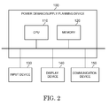
- Fig. 2 shows an example of the hardware layout of the power demand/supply planning device 100.
- the power demand/supply planning device 100 comprises a CPU 110, a memory 120, and input device 130, a display device 140 and communication device 150.
- Fig. 3 shows a functional block diagram of the power demand/supply planning device 100.
- the power demand/supply planning device 100 comprises: a demand forecasting section 101 that inputs input data and calculates a forecast demand value for the system as a whole; a supply planning section 102 that calculates a planned supply value, based on the demand forecast; a renewable energy generated amount forecasting section 103 (hereinafter referred to as generated amount forecasting section 103); and a difference extraction section 104 that calculates the difference (deviation) of the forecast demand value and the planned supply value.
- this difference allocation amount calculation section 105 that allocates a difference depending on the control capability of the distribution system 20 to each substation; and, with this difference allocation amount calculation section 105, there is connected an economic load allocation section 106 of the distribution system 20. In allocation of the differences with respect to the various items of equipment of the distribution systems 20, this economic load allocation section 106 performs cost optimization calculations.
- the items that are controllable by the power demand/supply planning device 100 are: the delivery (or transmission) voltage control device that is provided in the substation; the users 5 that are capable of responding to demand response; the accumulators 4 that are capable of being charged/discharging with respect to the distribution system; and the photovoltaic installations 2 or wind power installations 3 that are connected with the distribution system. Consequently, there are connected with the output side of the economic load allocation section 106 of the distribution system 20: a voltage/reactive power control section 161; a demand response control section 162; an accumulator control section 163; and a renewable energy control section 164.
- an economic load allocation section 107 of the base system which performs cost optimization calculation in allocation of the amounts to be generated by the various upper-level generators 1, is connected with the output side of the difference extraction section 104 through the difference allocation amount calculation section 105.
- An output control section 160 which is connected with the base system, of the various upper-level generators 1 is connected with the output side of this economic load allocation section 107 of the base system.
- the functions or processing procedures of the various sections constituting the power demand/supply planning device 100 are stored in the memory 120 as a computer program and are implemented by the CPU 110 reading and executing this computer program stored in the memory 120 as required.
- These various sections exchange data and/or control commands with the upper-level generators 1, the photovoltaic installations 2, wind power installations 3, accumulators 4 and users 5 of the various distribution systems 20, using the communication device 150 and communication network 200.
- the power demand/supply planning device 100 inputs data and/or commands etc. as required from the input device 130.
- the data and/or calculation results and control amounts etc. that are generated or processed by the various sections of the power demand/supply planning device 100 are output outside the power demand/supply planning device 100 by the display device 140 and communication device 150.
- Fig. 4 shows examples of the demand forecasting section 101 and supply planning section 102.
- the demand forecasting section 101 comprises a demand forecasting calculation section 1012 that forecasts the demand on the day of the forecast, based on input data 1011 such as:
- the supply planning section 102 comprises:
- Fig. 5 shows an example of the generated amount forecasting section 103. Since forecasting the amount of renewable energy is difficult because of the large effect of the weather, the forecast values are calculated by comparing real-time measurement data with past data.
- the generated amount forecasting section 103 forecasts the generated amount, totals the forecast values of each of the distribution systems 20, and thereby forecasts the generated amount of renewable energy of the system as a whole. If natural energy sources are connected with the base system, the amount generated thereby is also forecast and totaled.
- the generated amount forecasting section 103 comprises a wind power generated amount calculation section 1031 and a photovoltaic generated amount calculation section 1035.
- the wind power generated amount calculation section 1031 comprises: a similar-day calculation section 1033 that computes past days of similar weather to the day of the forecast, based on input data 1032 such as:
- the photovoltaic generated amount calculation section 1035 comprises: a similar-day calculation section 1037 that computes past days of similar weather to the day of the forecast, based on input data 1036 such as:
- the difference extraction section 104 calculates the difference between the forecast demand value and the planned supply value.
- the forecast value and the planned value obtained by the demand forecast section 101 and the supply planning section 102 are taken into account.
- the difference with respect to the planned supply value is calculated by subtracting the forecast generated value from the forecast demand value.
- the difference allocation amount calculation section 105 allocates the difference between the demand amount and supply amount calculated by the difference extraction section 104 to each substation constituting a power reception point of the various distribution systems 20, in a manner depending on the capabilities of the distribution system 20. Specifically, although the control amounts with respect to the various installations and users etc. connected with the various distribution systems 20 can be determined by a general economic load allocation section of a single distribution system, when the number of items to be controlled such as installations and users becomes very large, cost optimization calculations become complicated. In this embodiment, simplification and speeding up of the calculations is made possible by allocating differences to each distribution system 20 and controlling the installations or users in each distribution system 20 by implementing cost and optimization calculations with respect to these allocated differences in each individual distribution system 20.
- differences are allocated based on fixed parameters such as the scale, particulars of the installations and type of users of the distribution systems 20. For example, in the case of a distribution system 20 wherein:
- the economic load allocation section 106 of the distribution system 20 allocates such differences, of demand amount and supply amount, allocated to each distribution system 20 to the control sections 161 to 164 of the distribution systems 20 in question. In this allocation, appropriate allocations are set with respect to each of the items of equipment in the distribution systems 20 by a cost optimization technique. For this purpose, the economic load allocation section 106 is provided with an economic load allocation calculation section 1064 for obtaining an optimum solution. As shown in Fig.
- this calculation section 1064 receives input data 1061 relating to fixed components as specified in the equipment specification of the distribution system 20 in question, input data 1062 relating to components that fluctuate from time to time, such as real-time demand data, and difference data 1063 between the demand amount and supply amount in each distribution system 20 calculated by the difference allocation amount calculation section 105, and, based on these data, calculates the allocation amounts of lowest cost in each distribution system.
- input data 1061 relating to fixed components for example the following may be mentioned:
- input data 1062 relating to components that fluctuate from time to time, there may be mentioned for example the following:
- the economic load allocation calculation section 1064 that is provided in the economic load allocation section 106 of the distribution system calculates the economic load allocation with respect to each controllable item provided in the distribution system 20 in question.
- control quantities are calculated as follows for the voltage/reactive power control section 161, the demand response control section 162, the accumulator control section 163, and the renewable energy control section 164.
- the economic load allocation calculation section 1064 calculates control amounts of the various control sections 161 to 164 such that the difference x of the demand amount and supply amount will be equal to the total of the aforementioned control amounts.
- x a + b + c + d ...
- the unit costs y1, y2, y3, y4 applied to control of the respective control sections 161 to 164 are defined as follows. It should be noted that these costs are different for each distribution system 20, so economic load allocation calculation is required for each individual distribution system.
- the calculation section 1064 computes an equation (2) for finding a target function (object function) X such that the control cost is a minimum. Costs may change depending on the amount of electricity generated and the target function is thus a nonlinear function: computation is therefore performed using for example a nonlinear programming method (nonlinear planning method).
- X min ⁇ a * yl + b * y ⁇ 2 + c * y ⁇ 3 + d * y ⁇ 4
- an economic load allocation section can be employed that performs cost optimization calculation in distribution of generated amounts with respect to the various upper-level generators 1 by various techniques. For example, cost optimization calculation can be performed identifying the generation cost required by each upper-level generator 1, taking as parameters various costs such as fuel costs, delivery(transmission)/distribution loss, costs involved in stopping/restarting operation, environmental maintenance costs associated with operation, and depreciation and amortization of the various generators.
- the generated amount forecasting section 103 calculates the generated amounts of these (step 3), using the wind power generated amount calculation section 1031 and the photovoltaic generated amount calculation section 1035.
- the order in which this step 3 and the aforementioned step 2 performed is not important.
- the wind power generated amount calculation section 1031 calculates the wind power generated amount on the day of the forecast, based on input data 1032 such as
- the photovoltaic generated amount calculation section 1035 calculates the photovoltaic power generated amount on the day of the forecast, based on input data 1036 such as
- the supply planning section 102 calculates (step 4) the demand forecast amount and renewable energy forecast generated amount obtained from the aforementioned demand forecast section 101 and the generated amount forecasting section 103, and also calculates the planned supply values to the various distribution systems 20, based on for example load information input data 1021, such as
- the difference extraction section 104 calculates (step 5) the differences (deviations) between these. Regarding these differences, the range by which the planned supply value can exceed the forecast demand value represents the amount of power that can be provided by the upper-level generator 1 (YES in step 6).
- the amounts to be generated are allocated to the various upper-level generators 1 of the base system 10.
- the economic load allocation section 107 of the base system calculates (step 7) what manner of operating the various upper-level generators is most economic, and operates the various upper-level generators 1 (step 8) in accordance with the output result.
- the various distribution systems 20 differ as regards their scale, details of the equipment that they comprise and users, so, in this embodiment, the difference arising from this deficiency is allocated to the various distribution systems 20 (step 9) by the difference allocation amount calculation section 105.
- the economic load allocation section 106 of the distribution system calculates respective control amounts (step 10) by performing cost optimization calculations with respect to the control sections 161 to 164 of the various distribution systems 20, based on these differences that have thus been allocated to these various distribution systems 20, and controls the various items of equipment of the distribution systems (step 11) in accordance with the control amounts that are thus obtained.
- the power that is supplied to the various items of equipment possessed by the corresponding user 5 can be directly controlled, as a method of demand response.
- demands for reduction of the amount of power used by the user can be made by utilizing the communication device 150, and the response results can be received.
- control amounts that are optimal for minimizing the costs with respect to each of the distribution systems 20 that are being controlled can be derived by employing an economic load allocation technique. This means that, when setting planned supply values having in mind load leveling, it becomes possible for the operator to derive the minimum cost of achieving this.
- control amounts for the distribution equipment such as to minimize costs can be calculated with a view to establishing and achieving updated planned values for each of the distribution systems, based on the supply plan for the upper-layer system. Also, reflecting control of the distribution systems 20, it is possible to achieve optimization of control costs of the system as a whole by implementing economic load allocation with respect to the planned values that are thus generated.
- control of the installations and/or equipment or users of the various distribution systems can be performed directly, rather than allocating differences to the various distribution systems 20.
- Allocation of differences based on economic optimization could also be performed employing known techniques apart from that of the embodiment described above.
- the delivery voltage control device that is provided in the substations, users capable of responding to demand response, accumulators capable of charging/discharging with respect to the distribution systems and photovoltaic installations or wind power installations connected with the distribution systems can be treated individually or in combination.
- other equipment can be employed and the control parameters can also be appropriately selected.
- the present invention is employed in a power system or a power demand/supply planning device in which demand response etc. is performed in a distribution system.
Landscapes
- Engineering & Computer Science (AREA)
- Business, Economics & Management (AREA)
- Economics (AREA)
- Human Resources & Organizations (AREA)
- Strategic Management (AREA)
- Power Engineering (AREA)
- General Physics & Mathematics (AREA)
- Physics & Mathematics (AREA)
- Health & Medical Sciences (AREA)
- Tourism & Hospitality (AREA)
- General Business, Economics & Management (AREA)
- Theoretical Computer Science (AREA)
- Marketing (AREA)
- Public Health (AREA)
- Water Supply & Treatment (AREA)
- General Health & Medical Sciences (AREA)
- Primary Health Care (AREA)
- Entrepreneurship & Innovation (AREA)
- Game Theory and Decision Science (AREA)
- Quality & Reliability (AREA)
- Development Economics (AREA)
- Operations Research (AREA)
- General Engineering & Computer Science (AREA)
- Automation & Control Theory (AREA)
- Supply And Distribution Of Alternating Current (AREA)
- Management, Administration, Business Operations System, And Electronic Commerce (AREA)
Abstract
Description
- As a control system for a power system, a technique is known that may be described as the Demand Response technique. Demand response means that, in response to demand (in particular during peak demand) on the power network, a customer reduces the customer's own power consumption and/or supplies the excess power to other customers; or similar arrangements.
- As a control system for a power system, a technique is known that may be described as the Demand Response technique. Demand response means that, in response to demand (in particular during peak demand) on the power network, a customer reduces the customer's own power consumption and/or supplies the excess power to other customers; or similar arrangements.
- A known economic optimization technique employed in current power systems is economic load allocation. A known technique of economic optimization in the context of increasing adoption of natural energy is the technique of establishing a power generation forecast from the equipment data of the various natural energy installations and/or past results, and applying this to economic load allocation. An example of such a technique is disclosed in Laid-open Japanese Patent Publication Number
Tokkai 2012-34444 Tokkai 2012-34444 - In recent years, distributed power sources such as accumulators and renewable energy sources have become common and power sources are now to be found on the distribution side of the network also: a demand response arrangement has therefore been proposed in which the power employed by the user is controlled taking into account the presence and/or capability of power sources on the distribution side.
- In the prior art, the output allocation of the generators that are provided in the upper-level system is then calculated so as to optimize fuel consumption. In other words, in the prior art, although demand of the distribution system was taken into account, no consideration at all was given to power sources on the distribution side or to demand response control thereof.
- It is difficult to extract the maximum benefit from use of natural energy or the like power sources provided in the distribution system and/or the beneficial effect of demand response simply by fuel cost optimization of the generators located in the upper-level system. It is therefore not possible to derive the optimum solution, at which the power supply cost in both the upper-level system and the distribution system is a minimum, in the prior art.
- An object of the present embodiment is to provide a control system for a power system whereby the power supply costs in regard to the user and the various installations or equipment in the distribution system can be minimized.
- Another object of the present embodiment is to provide a control system for a power system whereby power supply costs can be minimized in the entire system including the base system, comprising a distribution system and upper-level generators.
- A control system for a power system according to the present embodiment is characterized in that it comprises the following items:
- (1) a demand forecasting section that calculates a forecast demand value in respect of the power system as a whole;
- (2) a supply planning section that calculates a planned supply value in respect of the power system as a whole;
- (3) a difference extraction section that finds the difference between said forecast demand value and planned supply value;
- (4) an economic load allocation section of the distribution system that allocates the difference obtained by said difference extraction section in respect of the controllable items provided in the distribution system, in accordance with a cost optimization technique; and
- (5) a control section that outputs to said controllable items control values based on the distribution amounts obtained by the economic load allocation section of said distribution system.
- In the embodiment, the power system has a plurality of distribution systems and may comprise a difference allocation amount calculation section that allocates the difference obtained by the aforementioned difference extraction section in accordance with the difference adjustment capability of each of these distribution systems.
- In the embodiment, the aforementioned power system comprises: a base system in which a plurality of upper-level generators are connected; and a plurality of distribution systems; the aforementioned power system may also be provided with an economic load allocation section of the base system, which allocates control amounts in respect of the aforementioned plurality of upper-level generators in accordance with a cost optimization technique.
-
-
Fig. 1 is a view showing the layout of a power system according to the embodiment, in which a natural energy power source has been introduced; -
Fig. 2 is a view showing the hardware layout of a power demand/supply planning device 100 according to the embodiment; -
Fig. 3 is a functional block diagram showing the layout of the power demand/supply planning device 100 according to the embodiment; -
Fig. 4 is a block diagram of ademand forecast section 101 andsupply planning section 102; -
Fig. 5 is a block diagram of a renewable energy generatedamount forecasting section 103; -
Fig. 6 is a block diagram of a distribution system economicload allocation section 106; and -
Fig. 7 is a flowchart showing the operation of a power demand/supply planning device according to the embodiment. -
Fig. 1 is a view showing the layout of a power system according to this embodiment. - A power system comprises: a
base system 10; adistribution system 20; and adistribution substation 30 that supplies power from thebase system 10 to thedistribution system 20. A plurality of upper-level generators 1 constituting controllable power sources are connected with thebase system 10. With thedistribution system 20, there are connected: aphotovoltaic installation 2; awind power installation 3; anaccumulator 4; users 5 capable of demand response; andusers 6 that are incapable of demand response. - Apart from power sources such as for example atomic power generators, thermal generators, or hydroelectric generators, the upper-
level generator 1 includes power sources that perform charging, such as pumped storage generators or secondary batteries. Thephotovoltaic installation 2 andwind power installation 3 that are connected with thedistribution system 20 constitute natural energy sources. Although not shown, thephotovoltaic installation 2 orwind power installation 3 or the like natural energy power sources oraccumulator 4 may be connected with thebase system 10. - The power demand/
supply planning device 100 is connected through acommunication network 200 with the upper-level generators 1, and thephotovoltaic installation 2,wind power installation 3,accumulator 4 and users 5 of thevarious distribution systems 20. -
Fig. 2 shows an example of the hardware layout of the power demand/supply planning device 100. The power demand/supply planning device 100 comprises aCPU 110, amemory 120, andinput device 130, adisplay device 140 andcommunication device 150. -
Fig. 3 shows a functional block diagram of the power demand/supply planning device 100. The power demand/supply planning device 100 comprises: ademand forecasting section 101 that inputs input data and calculates a forecast demand value for the system as a whole; asupply planning section 102 that calculates a planned supply value, based on the demand forecast; a renewable energy generated amount forecasting section 103 (hereinafter referred to as generated amount forecasting section 103); and adifference extraction section 104 that calculates the difference (deviation) of the forecast demand value and the planned supply value. - With the output side of this
difference extraction section 104, there is connected a difference allocationamount calculation section 105 that allocates a difference depending on the control capability of thedistribution system 20 to each substation; and, with this difference allocationamount calculation section 105, there is connected an economicload allocation section 106 of thedistribution system 20. In allocation of the differences with respect to the various items of equipment of thedistribution systems 20, this economicload allocation section 106 performs cost optimization calculations. - In this embodiment, the items that are controllable by the power demand/
supply planning device 100 are: the delivery (or transmission) voltage control device that is provided in the substation; the users 5 that are capable of responding to demand response; theaccumulators 4 that are capable of being charged/discharging with respect to the distribution system; and thephotovoltaic installations 2 orwind power installations 3 that are connected with the distribution system. Consequently, there are connected with the output side of the economicload allocation section 106 of the distribution system 20: a voltage/reactivepower control section 161; a demandresponse control section 162; anaccumulator control section 163; and a renewableenergy control section 164. - In addition, an economic
load allocation section 107 of the base system, which performs cost optimization calculation in allocation of the amounts to be generated by the various upper-level generators 1, is connected with the output side of thedifference extraction section 104 through the difference allocationamount calculation section 105. Anoutput control section 160, which is connected with the base system, of the various upper-level generators 1 is connected with the output side of this economicload allocation section 107 of the base system. - The functions or processing procedures of the various sections constituting the power demand/
supply planning device 100 are stored in thememory 120 as a computer program and are implemented by theCPU 110 reading and executing this computer program stored in thememory 120 as required. These various sections exchange data and/or control commands with the upper-level generators 1, thephotovoltaic installations 2,wind power installations 3,accumulators 4 and users 5 of thevarious distribution systems 20, using thecommunication device 150 andcommunication network 200. - The power demand/
supply planning device 100 inputs data and/or commands etc. as required from theinput device 130. The data and/or calculation results and control amounts etc. that are generated or processed by the various sections of the power demand/supply planning device 100 are output outside the power demand/supply planning device 100 by thedisplay device 140 andcommunication device 150. -
Fig. 4 shows examples of thedemand forecasting section 101 andsupply planning section 102. Thedemand forecasting section 101 comprises a demandforecasting calculation section 1012 that forecasts the demand on the day of the forecast, based on input data 1011 such as: - (1) real-time demand data;
- (2) meteorological data such as maximum air temperature, average air temperature and humidity; and
- (3) date data such as the day of the week, public holidays or special days.
- The
supply planning section 102 comprises: - (1) a supply
plan calculation section 1022 that calculates a supply plan based oninput data 1021 of for example load information such as the load volume and/or the location of occurrence of such load, and the demand forecast amounts calculated by the aforementioned demand/supplyforecast calculation section 1012. -
Fig. 5 shows an example of the generatedamount forecasting section 103. Since forecasting the amount of renewable energy is difficult because of the large effect of the weather, the forecast values are calculated by comparing real-time measurement data with past data. - For each of the natural energy sources such as
photovoltaic installations 2 orwind power installations 3 provided in thevarious distribution systems 20, the generatedamount forecasting section 103 forecasts the generated amount, totals the forecast values of each of thedistribution systems 20, and thereby forecasts the generated amount of renewable energy of the system as a whole. If natural energy sources are connected with the base system, the amount generated thereby is also forecast and totaled. The generatedamount forecasting section 103 comprises a wind power generatedamount calculation section 1031 and a photovoltaic generatedamount calculation section 1035. - The wind power generated
amount calculation section 1031 comprises: a similar-day calculation section 1033 that computes past days of similar weather to the day of the forecast, based oninput data 1032 such as: - (1) weather data such as wind speed or wind direction at the wind power installation location and
- (2) past weather data;
- The photovoltaic generated
amount calculation section 1035 comprises: a similar-day calculation section 1037 that computes past days of similar weather to the day of the forecast, based oninput data 1036 such as: - (1) weather data at the photovoltaic installation location and
- (2) past weather data; and an
illumination forecasting section 1038 that forecasts the illumination with respect to the photovoltaic installation, based on the computed similar day. The photovoltaic generatedamount calculation section 1035 calculates the generated amount of the day of the forecast, based on the forecast illumination (illuminance). Theinput data 1036 may include for example the length of the day, the height of the sun, the atmosphere, air temperature, humidity, wind direction, wind speed and degree of cloud cover. - The
difference extraction section 104 calculates the difference between the forecast demand value and the planned supply value. In this embodiment, not merely the forecast value and the planned value obtained by thedemand forecast section 101 and thesupply planning section 102, but also the forecast generated amount of renewable energy obtained by the generatedamount forecasting section 103 are taken into account. Specifically, the difference with respect to the planned supply value is calculated by subtracting the forecast generated value from the forecast demand value. - The difference allocation
amount calculation section 105 allocates the difference between the demand amount and supply amount calculated by thedifference extraction section 104 to each substation constituting a power reception point of thevarious distribution systems 20, in a manner depending on the capabilities of thedistribution system 20. Specifically, although the control amounts with respect to the various installations and users etc. connected with thevarious distribution systems 20 can be determined by a general economic load allocation section of a single distribution system, when the number of items to be controlled such as installations and users becomes very large, cost optimization calculations become complicated. In this embodiment, simplification and speeding up of the calculations is made possible by allocating differences to eachdistribution system 20 and controlling the installations or users in eachdistribution system 20 by implementing cost and optimization calculations with respect to these allocated differences in eachindividual distribution system 20. - In the allocation of differences by the difference allocation
amount calculation section 105, differences are allocated based on fixed parameters such as the scale, particulars of the installations and type of users of thedistribution systems 20. For example, in the case of adistribution system 20 wherein: - (1) the scale of the
distribution system 20 is large; - (2) the amount of electricity that can be accumulated by the
accumulator 4 is large; - (3) the number of users 5 capable of responding to demand response is large; and
- (4) many users have domestic power generation installations, the difference-absorption capability of the
distribution system 20 is high, so a larger difference can be allocated to such adistribution system 20. - The economic
load allocation section 106 of thedistribution system 20 allocates such differences, of demand amount and supply amount, allocated to eachdistribution system 20 to thecontrol sections 161 to 164 of thedistribution systems 20 in question. In this allocation, appropriate allocations are set with respect to each of the items of equipment in thedistribution systems 20 by a cost optimization technique. For this purpose, the economicload allocation section 106 is provided with an economic loadallocation calculation section 1064 for obtaining an optimum solution. As shown inFig. 6 , thiscalculation section 1064 receivesinput data 1061 relating to fixed components as specified in the equipment specification of thedistribution system 20 in question,input data 1062 relating to components that fluctuate from time to time, such as real-time demand data, anddifference data 1063 between the demand amount and supply amount in eachdistribution system 20 calculated by the difference allocationamount calculation section 105, and, based on these data, calculates the allocation amounts of lowest cost in each distribution system. - As
input data 1061 relating to fixed components, for example the following may be mentioned: - (1) The equipment specification of the
distribution system 20- (a) the capacity of the accumulator, and its charging/discharging loss and deterioration,
- (b) the load capacity, location and demand-response response rate,
- (c) the capacity of the voltage/reactive power control device and its location,
- (d) the renewable energy capacity and location, and
- (e) system information such as impedance.
- As
input data 1062 relating to components that fluctuate from time to time, there may be mentioned for example the following: - (1) real-time demand data,
- (2) renewable energy output amounts,
- (3) accumulator residual amounts,
- (4) measured values of active power, reactive power, and voltage etc. of the
distribution system 20. - As an example, the economic load
allocation calculation section 1064 that is provided in the economicload allocation section 106 of the distribution system calculates the economic load allocation with respect to each controllable item provided in thedistribution system 20 in question. First of all, control quantities are calculated as follows for the voltage/reactivepower control section 161, the demandresponse control section 162, theaccumulator control section 163, and the renewableenergy control section 164. -
- (1) voltage/reactive power control: a
- (2) demand response control: b,
- (3) accumulator control: c, and
- (4) renewable energy control: d
- As indicated by the following equation (expression) (1), the economic load
allocation calculation section 1064 calculates control amounts of thevarious control sections 161 to 164 such that the difference x of the demand amount and supply amount will be equal to the total of the aforementioned control amounts.
- The unit costs y1, y2, y3, y4 applied to control of the
respective control sections 161 to 164 are defined as follows. It should be noted that these costs are different for eachdistribution system 20, so economic load allocation calculation is required for each individual distribution system. -
- (1) Voltage/reactive power control: y1... the cost with respect to the apparent power, which increases or decreases when the voltage is controlled in the
distribution system 20. In thedistribution system 20, power consumption increases when the voltage is raised, increasing the generation cost. - (2) Demand response control: y2... the user reward for cooperating with demand-response.
- (3) Accumulator control: y3... average value of generation cost of upper-level generator in the time zone when the accumulator is being charged.
- (4) Renewable energy control: y4... when power generation by renewable energy is halted, the cost in supplying this power from the upper-level generator.
- Using the aforementioned control amounts and unit costs, the
calculation section 1064 computes an equation (2) for finding a target function (object function) X such that the control cost is a minimum. Costs may change depending on the amount of electricity generated and the target function is thus a nonlinear function: computation is therefore performed using for example a nonlinear programming method (nonlinear planning method).
- Nonlinear programming methods are set out below.
Gill, P. E., W. Murray, M. H. Wright "Numerical Linear Algebra and Optimization" Vol.1, Addison Wesley, 1991 - K. Schittkowski (1981): The nonlinear programming method of Wilson, Han and Powell.
- Part 1: Convergence analysis, Numerische Mathematik, Vol.38, 83-114,
- Part 2: An efficient implementation with linear least-squares sub-problems, Numerische Mathematik, Vol.38, 115-127
- For the economic
load allocation section 107 of the base system, an economic load allocation section can be employed that performs cost optimization calculation in distribution of generated amounts with respect to the various upper-level generators 1 by various techniques. For example, cost optimization calculation can be performed identifying the generation cost required by each upper-level generator 1, taking as parameters various costs such as fuel costs, delivery(transmission)/distribution loss, costs involved in stopping/restarting operation, environmental maintenance costs associated with operation, and depreciation and amortization of the various generators. - A specific description of the operation of a power demand/
supply planning device 100 according to this embodiment is given below with reference toFig. 7 . - As shown by the flowchart of
Fig. 7 , when the input data 1011 comprising for example - (1) real-time demand data,
- (2) weather data such as maximum temperature, average temperature and humidity, and
- (3) date data such as day of the week, public holidays and special days
- Likewise, the generated
amount forecasting section 103 calculates the generated amounts of these (step 3), using the wind power generatedamount calculation section 1031 and the photovoltaic generatedamount calculation section 1035. The order in which thisstep 3 and theaforementioned step 2 performed is not important. - Specifically, the wind power generated
amount calculation section 1031 calculates the wind power generated amount on the day of the forecast, based oninput data 1032 such as - (1) weather data such as the wind speed and wind direction of the location of installation of the wind power generation installation, and
- (2) past weather data.
- The photovoltaic generated
amount calculation section 1035 calculates the photovoltaic power generated amount on the day of the forecast, based oninput data 1036 such as - (1) weather data of the location of installation of the photovoltaic generation installation, and
- (2) past weather data.
- The
supply planning section 102 calculates (step 4) the demand forecast amount and renewable energy forecast generated amount obtained from the aforementioneddemand forecast section 101 and the generatedamount forecasting section 103, and also calculates the planned supply values to thevarious distribution systems 20, based on for example loadinformation input data 1021, such as - (1) the load capacity and/or the generating location thereof, in each system.
- After obtaining the demand forecast values and the planned supply values, the
difference extraction section 104 calculates (step 5) the differences (deviations) between these. Regarding these differences, the range by which the planned supply value can exceed the forecast demand value represents the amount of power that can be provided by the upper-level generator 1 (YES in step 6). - In this situation, the amounts to be generated are allocated to the various upper-
level generators 1 of thebase system 10. In other words, the economicload allocation section 107 of the base system calculates (step 7) what manner of operating the various upper-level generators is most economic, and operates the various upper-level generators 1 (step 8) in accordance with the output result. - On the other hand, in the case of some of the differences, it may happen that the range by which the planned supply value undershoots the forecasting demand amount exceeds the amount that can be generated by the upper-layer generator 1 (NO in step 6). The amount of the deficiency is borne by the
various distribution systems 20. However, thevarious distribution systems 20 differ as regards their scale, details of the equipment that they comprise and users, so, in this embodiment, the difference arising from this deficiency is allocated to the various distribution systems 20 (step 9) by the difference allocationamount calculation section 105. - The economic
load allocation section 106 of the distribution system calculates respective control amounts (step 10) by performing cost optimization calculations with respect to thecontrol sections 161 to 164 of thevarious distribution systems 20, based on these differences that have thus been allocated to thesevarious distribution systems 20, and controls the various items of equipment of the distribution systems (step 11) in accordance with the control amounts that are thus obtained. When this is done, the power that is supplied to the various items of equipment possessed by the corresponding user 5 can be directly controlled, as a method of demand response. Also, demands for reduction of the amount of power used by the user can be made by utilizing thecommunication device 150, and the response results can be received. - With this embodiment, control amounts that are optimal for minimizing the costs with respect to each of the
distribution systems 20 that are being controlled can be derived by employing an economic load allocation technique. This means that, when setting planned supply values having in mind load leveling, it becomes possible for the operator to derive the minimum cost of achieving this. - Thus, in this embodiment, it becomes possible to appreciate beforehand what degree of economic benefit can be anticipated from each of the
various distribution systems 20 that are under operational control. An efficient equipment plan can therefore be established when upgrading the equipment of thevarious distribution systems 20. - In this embodiment, setting of price levels is facilitated, since it is possible to evaluate beforehand the economic benefits of demand response, whose more widespread deployment is currently being planned. In particular, control amounts for the distribution equipment such as to minimize costs can be calculated with a view to establishing and achieving updated planned values for each of the distribution systems, based on the supply plan for the upper-layer system. Also, reflecting control of the
distribution systems 20, it is possible to achieve optimization of control costs of the system as a whole by implementing economic load allocation with respect to the planned values that are thus generated. - With this embodiment, power supply without shortfall as well as economic optimization by the upper-layer system generators can be achieved. In this way, economic optimization can be achieved in the power system as a whole, while making maximum use of the control means of the
distribution systems 20. - The present invention is not directly restricted to the embodiments described above and could be put into practice at the implementation stage with the structural elements modified in a range not departing from the gist of the invention. Also, various inventions can be formed by suitable combination of the plurality of structural elements disclosed in the above embodiment. For example, some structural elements can be deleted from the totality of structural elements disclosed in the embodiment. In addition, structural elements belonging to different embodiments can be combined as appropriate.
- For example, if ample computing power is available, control of the installations and/or equipment or users of the various distribution systems can be performed directly, rather than allocating differences to the
various distribution systems 20. Allocation of differences based on economic optimization could also be performed employing known techniques apart from that of the embodiment described above. - Regarding the generators and other installations or equipment of the
base system 10 or thevarious distribution systems 20 that are the subject of control, the delivery voltage control device that is provided in the substations, users capable of responding to demand response, accumulators capable of charging/discharging with respect to the distribution systems and photovoltaic installations or wind power installations connected with the distribution systems can be treated individually or in combination. Apart from the embodiments described above, other equipment can be employed and the control parameters can also be appropriately selected. - Although, in the embodiment described above, a plurality of upper-
level generators 1 connected with the base system were controlled by an economic optimization technique, it would also be possible to exercise control solely of the various items of equipment or installations in the individual distribution systems, without combining these with the base system. Instead of providing a generated amount forecasting section for the renewable energy, it is also possible to calculate the demand/supply differences (deviations) by means of a demand forecasting section and supply planning section. - The present invention is employed in a power system or a power demand/supply planning device in which demand response etc. is performed in a distribution system.
Claims (5)
- A control system for a power system comprising:a demand forecasting section that calculates a demand forecast value of said power system as a whole;a supply planning section that calculates a planned supply value of said power system as a whole;a difference extraction section that finds a difference between said demand forecast value and planned supply value;an economic load allocation section of a distribution system that allocates said difference obtained by said difference extraction section with respect to control subjects provided in said distribution system, in accordance with a cost optimization technique; anda control section that outputs control amounts based on said allocated amounts obtained by said economic load allocation section of said distribution system to said control subjects.
- The control system for a power system according to claim 1,
wherein said power system comprises a plurality of distribution systems, comprising a difference allocation amount calculation section that allocates said difference obtained by said difference extraction section in accordance with a respective difference adjustment capability of distribution systems. - The control system for a power system according to claim 1 or claim 2,
wherein said power system comprises a base system connected with a plurality of upper-level generators, and a plurality of distribution systems;
comprising an economic load allocation section of the base system that allocates control amounts with respect to said plurality of upper-level generators in accordance with a cost optimization technique. - The control system for a power system according to claim 1 or claim 2,
wherein said power system comprises renewable energy generation equipment and said difference extraction section finds said difference by subtracting a generated amount obtained by said renewable energy generated amount forecasting section from a demand amount forecast value. - The control system for a power system according to claim 1,
wherein said control subjects are any or a combination of a delivered voltage control device provided in a substation, a user that is capable of demand response, an accumulator capable of charging/discharging with respect to a distribution system, and a photovoltaic installation or wind power installation connected with said distribution system.
Applications Claiming Priority (2)
| Application Number | Priority Date | Filing Date | Title |
|---|---|---|---|
| JP2013010809A JP2014143835A (en) | 2013-01-24 | 2013-01-24 | Control system for power system |
| PCT/JP2014/000345 WO2014115556A1 (en) | 2013-01-24 | 2014-01-23 | Power system control system |
Publications (2)
| Publication Number | Publication Date |
|---|---|
| EP2950414A1 true EP2950414A1 (en) | 2015-12-02 |
| EP2950414A4 EP2950414A4 (en) | 2016-08-31 |
Family
ID=51227348
Family Applications (1)
| Application Number | Title | Priority Date | Filing Date |
|---|---|---|---|
| EP14742951.8A Withdrawn EP2950414A4 (en) | 2013-01-24 | 2014-01-23 | ELECTRIC SYSTEM CONTROL SYSTEM |
Country Status (4)
| Country | Link |
|---|---|
| US (1) | US20150324935A1 (en) |
| EP (1) | EP2950414A4 (en) |
| JP (1) | JP2014143835A (en) |
| WO (1) | WO2014115556A1 (en) |
Cited By (4)
| Publication number | Priority date | Publication date | Assignee | Title |
|---|---|---|---|---|
| CN105449670A (en) * | 2015-12-11 | 2016-03-30 | 国家电网公司 | Load characteristic analysis method for power distribution network |
| CN105743113A (en) * | 2014-12-12 | 2016-07-06 | 国家电网公司 | Multi-infeed direct-current transmission system harmonic instability judgment method |
| CN105914742A (en) * | 2016-05-09 | 2016-08-31 | 国家电网公司 | On-load voltage regulation device control system and method based on flexible control technology |
| WO2017200658A3 (en) * | 2016-04-22 | 2018-04-26 | James Wolter | Energy apparatuses, energy systems, and energy management methods including energy storage |
Families Citing this family (17)
| Publication number | Priority date | Publication date | Assignee | Title |
|---|---|---|---|---|
| JP5931991B2 (en) * | 2014-10-01 | 2016-06-08 | 中国電力株式会社 | Voltage regulator |
| SG10201406883UA (en) * | 2014-10-23 | 2016-05-30 | Sun Electric Pte Ltd | "Power Grid System And Method Of Consolidating Power Injection And Consumption In A Power Grid System" |
| WO2016076008A1 (en) * | 2014-11-10 | 2016-05-19 | 日本電気株式会社 | Device for controlling electrical power supply and demand, method for controlling electrical power supply and demand, and program |
| CN104463370A (en) * | 2014-12-12 | 2015-03-25 | 国家电网公司 | Power distribution network resource optimization allocation system and method |
| JP6470997B2 (en) * | 2015-02-19 | 2019-02-13 | 株式会社Looop | Power supply control device, power supply control method, and power supply control program |
| JP6235061B2 (en) * | 2015-03-27 | 2017-11-22 | 株式会社九電工 | Power supply system using renewable energy-based power generation facilities |
| WO2016158777A1 (en) * | 2015-03-27 | 2016-10-06 | 株式会社九電工 | Power supply system in which renewable energy-utilizing power generation facility is used |
| US20170053361A1 (en) * | 2015-08-20 | 2017-02-23 | Sinogreenergy Consultant Co. Ltd. | Power output calculating method of a solar power plant |
| CN105096010A (en) * | 2015-09-07 | 2015-11-25 | 国网天津市电力公司 | Grid planning method for considering demand side management |
| US10234885B2 (en) | 2016-06-13 | 2019-03-19 | Sun Electric Digital Stream Ltd. | Method and system for facilitating auditing of power generation and allocation thereof to consumption loads |
| US10468883B2 (en) * | 2016-08-08 | 2019-11-05 | Awadhesh Kumar | Method and system for facilitating optimization of energy in a distributed environment |
| KR101981793B1 (en) * | 2016-09-30 | 2019-05-23 | 가천대학교 산학협력단 | Effective distribution network operation method using grid acceptance information |
| JP7068557B2 (en) * | 2019-07-19 | 2022-05-16 | 三菱電機株式会社 | Power controller and power distribution plan setting method |
| CN113592124A (en) * | 2020-04-30 | 2021-11-02 | 贵州电网有限责任公司 | Power supply unit networking method based on unit sub-supply area optimized matching |
| JP7607548B2 (en) * | 2021-11-30 | 2024-12-27 | 三菱電機株式会社 | Learning device, power demand inference device, grid control system, supply and demand control system, facility formation support system and program |
| JP7605154B2 (en) * | 2022-02-25 | 2024-12-24 | トヨタ自動車株式会社 | Demand forecasting system, demand forecasting method, and program |
| JP7809841B2 (en) * | 2022-12-27 | 2026-02-02 | 日立Geベルノバニュークリアエナジー株式会社 | Nuclear power plant interconnection control system, modular nuclear power plant, and interconnection control method |
Family Cites Families (15)
| Publication number | Priority date | Publication date | Assignee | Title |
|---|---|---|---|---|
| JP2004040956A (en) * | 2002-07-05 | 2004-02-05 | Osaka Gas Co Ltd | Power supply management method |
| JP4658089B2 (en) * | 2007-05-23 | 2011-03-23 | 三菱電機株式会社 | Generator operation plan formulation device, operation plan formulation method, and program for executing the device and method |
| US8068938B2 (en) * | 2009-05-15 | 2011-11-29 | General Electric Company | Method and system for managing a load demand on an electrical grid |
| US20110106327A1 (en) * | 2009-11-05 | 2011-05-05 | General Electric Company | Energy optimization method |
| JP2011114945A (en) * | 2009-11-26 | 2011-06-09 | Fuji Electric Systems Co Ltd | Power supply planning system, and program of the same |
| JP2011114944A (en) * | 2009-11-26 | 2011-06-09 | Fuji Electric Systems Co Ltd | Power demand estimation device, and program of the same |
| JP2011124287A (en) * | 2009-12-08 | 2011-06-23 | Sony Corp | Electric power generation volume estimating apparatus, electric power generation volume estimating system, electric power generation amount estimating method, and computer program |
| JP2012034444A (en) * | 2010-07-28 | 2012-02-16 | Toshiba Corp | Power supply-demand planning device and method thereof |
| JP5101675B2 (en) * | 2010-09-09 | 2012-12-19 | 株式会社東芝 | Supply-demand balance control device |
| JP2012175825A (en) * | 2011-02-22 | 2012-09-10 | Mitsubishi Electric Corp | Power management system |
| WO2012120623A1 (en) * | 2011-03-07 | 2012-09-13 | 株式会社日立製作所 | System, method, and computer program for energy consumption management |
| US8689020B2 (en) * | 2011-08-16 | 2014-04-01 | General Electric Company | Method, system and computer program product for scheduling demand events |
| US8886362B2 (en) * | 2012-03-30 | 2014-11-11 | General Electric Company | Integrated distribution system optimization |
| JP2013240154A (en) * | 2012-05-11 | 2013-11-28 | Toshiba Corp | Electric power supply/demand regulating device and its method |
| EP3071977A4 (en) * | 2013-11-22 | 2017-06-14 | Mansfield, Stephen Kenneth | Methods and systems for energy arbitrage |
-
2013
- 2013-01-24 JP JP2013010809A patent/JP2014143835A/en active Pending
-
2014
- 2014-01-23 WO PCT/JP2014/000345 patent/WO2014115556A1/en not_active Ceased
- 2014-01-23 EP EP14742951.8A patent/EP2950414A4/en not_active Withdrawn
-
2015
- 2015-07-22 US US14/806,254 patent/US20150324935A1/en not_active Abandoned
Cited By (6)
| Publication number | Priority date | Publication date | Assignee | Title |
|---|---|---|---|---|
| CN105743113A (en) * | 2014-12-12 | 2016-07-06 | 国家电网公司 | Multi-infeed direct-current transmission system harmonic instability judgment method |
| CN105743113B (en) * | 2014-12-12 | 2019-04-19 | 国家电网公司 | A method for judging harmonic instability of multi-feed HVDC transmission system |
| CN105449670A (en) * | 2015-12-11 | 2016-03-30 | 国家电网公司 | Load characteristic analysis method for power distribution network |
| CN105449670B (en) * | 2015-12-11 | 2018-03-20 | 国家电网公司 | A kind of distribution network load characteristic analysis method |
| WO2017200658A3 (en) * | 2016-04-22 | 2018-04-26 | James Wolter | Energy apparatuses, energy systems, and energy management methods including energy storage |
| CN105914742A (en) * | 2016-05-09 | 2016-08-31 | 国家电网公司 | On-load voltage regulation device control system and method based on flexible control technology |
Also Published As
| Publication number | Publication date |
|---|---|
| US20150324935A1 (en) | 2015-11-12 |
| EP2950414A4 (en) | 2016-08-31 |
| JP2014143835A (en) | 2014-08-07 |
| WO2014115556A1 (en) | 2014-07-31 |
Similar Documents
| Publication | Publication Date | Title |
|---|---|---|
| EP2950414A1 (en) | Power system control system | |
| Ghasemi et al. | Optimal energy management of a renewable-based isolated microgrid with pumped-storage unit and demand response | |
| Motalleb et al. | Optimal placement and sizing of the storage supporting transmission and distribution networks | |
| Xiong et al. | Optimal planning of storage in power systems integrated with wind power generation | |
| Sachs et al. | A two-stage model predictive control strategy for economic diesel-PV-battery island microgrid operation in rural areas | |
| KR102238624B1 (en) | System and method for operating virtual power plant based on multi-objective function | |
| Gupta et al. | A robust optimization based approach for microgrid operation in deregulated environment | |
| Pandžić et al. | Near-optimal method for siting and sizing of distributed storage in a transmission network | |
| Bahramirad et al. | Practical modeling of Smart Grid SMS™ storage management system in a microgrid | |
| Oskouei et al. | Scenario-based stochastic optimal operation of wind, photovoltaic, pump-storage hybrid system in frequency-based pricing | |
| CN103825304B (en) | Methods of controlling the power grid | |
| KR102396712B1 (en) | Energy management system and method for minimizing the power purchase cost of microgrid using the same | |
| Weniger et al. | Integration of PV power and load forecasts into the operation of residential PV battery systems | |
| JP6543145B2 (en) | Peak power prediction device, power management system and peak power prediction method | |
| Sowa et al. | Multi-criteria operation strategies of power-to-heat-systems in virtual power plants with a high penetration of renewable energies | |
| KR20210100699A (en) | hybrid power plant | |
| Prudhviraj et al. | Stochastic energy management of microgrid with nodal pricing | |
| Bridier et al. | A heuristic approach for optimal sizing of ESS coupled with intermittent renewable sources systems | |
| Silva et al. | Hour-ahead energy resource management in university campus microgrid | |
| JP2015065740A (en) | Optimal control method for smart house | |
| Guinot et al. | Economic impact of performances degradation on the competitiveness of energy storage technologies–Part 1: Introduction to the simulation-optimization platform ODYSSEY and elements of validation on a PV-hydrogen hybrid system | |
| EP3104487A1 (en) | Energy management system | |
| Srinivasan et al. | Performance enhancement for microgrids under the demand uncertainties with the presence of multiple DGs through stochastic ranking algorithm | |
| KR102472630B1 (en) | Power generation management system | |
| KR102471609B1 (en) | Photovoltaics generation forecasting system |
Legal Events
| Date | Code | Title | Description |
|---|---|---|---|
| PUAI | Public reference made under article 153(3) epc to a published international application that has entered the european phase |
Free format text: ORIGINAL CODE: 0009012 |
|
| 17P | Request for examination filed |
Effective date: 20150615 |
|
| AK | Designated contracting states |
Kind code of ref document: A1 Designated state(s): AL AT BE BG CH CY CZ DE DK EE ES FI FR GB GR HR HU IE IS IT LI LT LU LV MC MK MT NL NO PL PT RO RS SE SI SK SM TR |
|
| AX | Request for extension of the european patent |
Extension state: BA ME |
|
| DAX | Request for extension of the european patent (deleted) | ||
| A4 | Supplementary search report drawn up and despatched |
Effective date: 20160729 |
|
| RIC1 | Information provided on ipc code assigned before grant |
Ipc: H02J 3/46 20060101ALI20160725BHEP Ipc: H02J 3/00 20060101AFI20160725BHEP Ipc: G06Q 10/04 20120101ALI20160725BHEP Ipc: G06Q 50/06 20120101ALI20160725BHEP |
|
| STAA | Information on the status of an ep patent application or granted ep patent |
Free format text: STATUS: THE APPLICATION HAS BEEN WITHDRAWN |
|
| 18W | Application withdrawn |
Effective date: 20170215 |