EP2950062A1 - Measuring device - Google Patents
Measuring device Download PDFInfo
- Publication number
- EP2950062A1 EP2950062A1 EP15168118.6A EP15168118A EP2950062A1 EP 2950062 A1 EP2950062 A1 EP 2950062A1 EP 15168118 A EP15168118 A EP 15168118A EP 2950062 A1 EP2950062 A1 EP 2950062A1
- Authority
- EP
- European Patent Office
- Prior art keywords
- housing
- measuring device
- measuring
- measuring electrode
- connecting member
- Prior art date
- Legal status (The legal status is an assumption and is not a legal conclusion. Google has not performed a legal analysis and makes no representation as to the accuracy of the status listed.)
- Granted
Links
Images



Classifications
-
- A—HUMAN NECESSITIES
- A61—MEDICAL OR VETERINARY SCIENCE; HYGIENE
- A61B—DIAGNOSIS; SURGERY; IDENTIFICATION
- A61B5/00—Measuring for diagnostic purposes; Identification of persons
- A61B5/05—Detecting, measuring or recording for diagnosis by means of electric currents or magnetic fields; Measuring using microwaves or radio waves
- A61B5/053—Measuring electrical impedance or conductance of a portion of the body
- A61B5/0537—Measuring body composition by impedance, e.g. tissue hydration or fat content
-
- G—PHYSICS
- G01—MEASURING; TESTING
- G01G—WEIGHING
- G01G19/00—Weighing apparatus or methods adapted for special purposes not provided for in the preceding groups
- G01G19/44—Weighing apparatus or methods adapted for special purposes not provided for in the preceding groups for weighing persons
- G01G19/50—Weighing apparatus or methods adapted for special purposes not provided for in the preceding groups for weighing persons having additional measuring devices, e.g. for height
-
- A—HUMAN NECESSITIES
- A61—MEDICAL OR VETERINARY SCIENCE; HYGIENE
- A61B—DIAGNOSIS; SURGERY; IDENTIFICATION
- A61B5/00—Measuring for diagnostic purposes; Identification of persons
- A61B5/68—Arrangements of detecting, measuring or recording means, e.g. sensors, in relation to patient
- A61B5/6801—Arrangements of detecting, measuring or recording means, e.g. sensors, in relation to patient specially adapted to be attached to or worn on the body surface
- A61B5/6843—Monitoring or controlling sensor contact pressure
-
- A—HUMAN NECESSITIES
- A61—MEDICAL OR VETERINARY SCIENCE; HYGIENE
- A61B—DIAGNOSIS; SURGERY; IDENTIFICATION
- A61B2560/00—Constructional details of operational features of apparatus; Accessories for medical measuring apparatus
- A61B2560/04—Constructional details of apparatus
- A61B2560/0462—Apparatus with built-in sensors
- A61B2560/0468—Built-in electrodes
Definitions
- measuring electrodes are placed in contact with the hands and/or feet to measure the body weight or bioelectrical impedance of a human body.
- Information such as bioelectrical impedance obtained through the measuring electrodes is sent as electrical signals to, for example, an operation circuit provided on a substrate, is subjected to the operation of the operation circuit, and is then sent to a user as information on the body composition such as body fat rate.
- the piezoelectric element and the auxiliary power supply unit are connected to each other by the lead in the weighing device disclosed in Japanese Laid-open Patent Publication 2011-185689 , however, it has the following problems.
- a process of soldering the lead to the piezoelectric element is required. More specifically, it is necessary to place the weighing pan after the piezoelectric element and the auxiliary power supply unit are connected by the lead in advance, and, therefore, there seems to be a limitation in the assembly process.
- the use of soldering and a lead may cause failure or defect of electrical connection, because the solder joint may degrade and the lead may break due to long-term use.
- the present invention has been made to solve the above problems.
- An object of the present invention is to provide a measuring device which can be easily assembled and can be stably used for a long time.
- a measuring device comprising: a first housing having at least one measuring electrode; a second housing connected to the first housing and housing a substrate which has at least one terminal and is used for making measurements; and at least one connecting member disposed between the first housing and the second housing, wherein the at least one connecting member is formed of a unitary member, and wherein one end of the at least connecting member is connected to the at least one terminal, while the other end of the at least connecting member is in contact with the at least one measuring electrode due to an elastic force of the at least one connecting member itself.
- the first housing 2 comprises: a top plate 2A formed in a square shape in top view; and a left side wall 2L, a right side wall 2R, a front wall 2F and a back wall 2B which respectively extend downward from the top plate 2A.
- a front-back direction the direction extending from the front wall 2F to the back wall 2B (i.e. the direction in which a user commonly steps on and off when using it) will be referred to as front-back direction.
- the side where the front wall 2F is positioned will be expressed as e.g. front or front side
- the side where the back wall 2B is positioned will be expressed as e.g. back or back side.
- each of the front wall 2F and the back wall 2B has two lower corner portions, each of which is formed to make a substantially right angle when viewed in the front-back direction.
- the area under the top plate 2A that is surrounded by the front wall 2F, the back wall 2B, the left side wall 2L and the right side wall 2R is referred to as space S 1.
- the space S1 opens downward.
- the front wall 2F, the back wall 2B, the left side wall 2L and the right side wall 2R are set to have the same vertical dimension as each other.
- the first housing 2 having the above structure is integrally formed, for example, of a resin material.
- the top plate 2A has the plurality of measuring electrodes 10 formed thereon which are placed in contact with a human body to be measured for various measurements.
- Each of the measuring electrodes 10 comprises an electrode member having a square shape in top view and formed in a thin plate shape. Four measuring electrodes 10 are provided near the four corners of the top plate 2A, respectively.
- the measuring electrodes 10 comprise: a first measuring electrode 11 and a second measuring electrode 12 arranged in the front-back direction along one side of the top plate 2A close to the left side wall 2L; and a third measuring electrode 13 and a fourth measuring electrode 14 arranged in the front-back direction along one side of the top plate 2A close to the right side wall 2R.
- the first measuring electrode 11 and the third measuring electrode 13 are electrodes for supplying current.
- a current supplied by a current supply device (not shown) flows between the first measuring electrode 11 and the third measuring electrode 13, and flows into the body of the user.
- the second measuring electrode 12 and the fourth measuring electrode 14 are electrodes used for making measurements.
- a potential difference is generated between the second measuring electrode 12 and the fourth electrode 14. This potential difference is detected by the second measuring electrode 12 and the fourth measuring electrode 14.
- the first measuring electrode 11 and the third measuring electrode 13 are spaced from the second measuring electrode 12 and the fourth measuring electrode 14, respectively, by a predetermined distance. More specifically, the distance S between one side of the first measuring electrode 11 (the third measuring electrode 13) and one side of the second measuring electrode 12 (the fourth measuring electrode 14), facing the one side of the first measuring electrode 11 (the third measuring electrode 13), is, for example, about 70mm.
- Each of the measuring electrodes 10 has an upper surface formed in a smooth flat surface and exposed outward from above the top plate 2A. Further, each measuring electrode 10 has a lower surface formed in a smooth flat surface and exposed toward the above-described space S1 from below the top plate 2A. In other words, each measuring electrode 10 is arranged to penetrate through the top plate 2A in the thickness direction. Note that each measuring electrode 10 is fixed to the top plate 2A by a fixing member (not shown) so as to prevent the measuring electrode 10 from dropping off.
- each measuring electrode 10 described above is arranged to penetrate through the top plate 2A in the thickness direction, it is also possible to form a recess in an upper surface of the top plate 2A, and to form, in a portion of the recess, a through-hole extending through a lower surface of the top plate 2A, so as to place the measuring electrode 10 in the recess.
- each measuring electrode 10 and the upper surface of the top plate 2A are formed so as to be smoothly connected to each other. This makes it possible to make measurements without causing a raised portion of the measuring electrode 10 to put unnecessary pressure on a human body when the measuring electrode 10 is in contact with the human body, and also makes it possible to ensure aesthetic appearance of products.
- a display window 100 is provided in an area of the top plate 2A between the first electrode 11 and the third electrode 13. At least a part of the display window 100 is formed of a transparent resin, glass or the like so as to inform measurement results displayed on a display unit 45, which is provided on a substrate 40 described later, to the outside through the display window 100.
- the second housing 3 is a box-shaped member having a base and is connected to the above-described first housing 2 in the vertical direction.
- the second housing 3 comprises: a bottom plate 3U formed in a substantially square shape in top view; and a second housing front wall 3F, a second housing back wall 3B, a second housing left side wall 3L and a second housing right side wall 3R which extend upward respectively from the bottom plate 3U and substantially perpendicular to the bottom plate 3U.
- the second housing front wall 3F, the second housing back wall 3B, the second housing left side wall 3L and the second housing right side wall 3R are set to have substantially the same vertical dimension as that of the front wall 2F, the back wall 2B, the left side wall 2L and the right side wall 2R of the first housing 2, respectively.
- the longitudinal ribs 61 and the lateral ribs 62 can withstand the load (weight of the user), since the space S2 is divided by the plurality of longitudinal ribs 61 and lateral ribs 62. Thus, the space S2 is not broken by the weight of the user, allowing the measuring device 1 to maintain its shape.
- a front area of the space S2 is not provided with either the longitudinal ribs 61 or the lateral ribs 62, and is used as a substrate housing section S3.
- a substrate 40 described later is housed in the substrate housing section S3, and, therefore, the shape and dimensions of the substrate housing section S3 are determined by the shape and dimensions of the substrate 40.
- the substrate housing section S3 is substantially square-shaped in top view.
- the substrate 40 comprises: a circuit (not shown) for conducting a measurement process by using signals obtained from the measuring electrodes 10 described above; and a display unit 45 for displaying output results of the circuit.
- a circuit not shown
- a display unit 45 for displaying output results of the circuit.
- terminals 41, 42, 43 and 44 electrically connected to the circuit via printed wiring are provided. Measured values obtained from the measuring electrodes 10 are input to the terminals 41, 42, 43 and 44 via the connecting members 20, 21, 22 and 23, respectively.
- the connecting members 20, 21, 22, and 23 are housed in the space S2 of the second housing 3.
- the longitudinal ribs 61 and the lateral ribs 62 are provided in the space S2 of the second housing 3 as described above, the longitudinal ribs 61 and the lateral ribs 62 are notched to form housing grooves 63 in the areas of the space S2 where the connecting members 20, 21, 22 and 23 are housed, respectively.
- the housing grooves 63 are linear grooves extending in the same plane along the direction from the terminals 41, 42, 43 and 44 on the substrate 40 toward the first measuring electrode 11, the second measuring electrode 12, the third measuring electrode 13 and the fourth measuring electrode 14, respectively.
- a conductive member holding member 63A is provided at an end of each housing groove 63, which is located opposite to where the substrate 40 is located.
- Each conductive member holding member 63A is a substantially cylindrical-shaped boss portion which extends upward from the bottom plate 3U in the space S2.
- the conductive member holding members 63A engage with and hold conductive members 20A, 21A, 22A and 23A, respectively, which will be described later.
- the space S2 is an area over the bottom plate 3U of the second case 3 and surrounded by the second housing front wall 3F, the second housing back wall 3B, the second housing left side wall 3L and the second housing right side wall 3R.
- FIG. 3 is a schematic perspective view showing a state in which the second housing 3 and the connecting members 20, 21, 22, and 23 in the measuring device 1 according to the exemplary embodiment of the present invention are assembled together.
- the ends of the lead members 20B, 21B, 22B and 23B which are located opposite to where the conductive members 20A, 21A, 22A and 23A are provided, are connected by soldering or the like, for example, to the terminals 41, 42, 43 and 44, respectively, which are provided on the substrate 40.
- the conductive members 20A, 21 A, 22A and 23A are fitted to the corresponding conductive member holding members 63A, respectively, from above so as to be held thereby.
- the dimensions in the radial directions of the conductive member holding members 63A are set to be substantially the same as (i.e., completely the same as, a little larger than or a little smaller than) the inner diameters of the coil springs of the conductive members 20A, 21A, 22A and 23A, respectively.
- the dimension in the radial direction of each conductive member holding member 63A can be designed to decrease from a lower end to an upper end of the conductive member holding member 63A.
- the substrate 40 and the connecting members 20, 21, 22 and 23 in the substrate housing section S3 and the housing grooves 63, respectively, after the connecting members 20, 21, 22 and 23 are connected to the terminals 41, 42, 43 and 44 of the substrate 40, respectively, in advance.
- FIG. 4 is a schematic top plan view of the measuring device 1 thus assembled. As shown in FIG.
- the assembled measuring device 1 is structured such that, when viewed from the direction in which the first housing 2 is connected to the second housing 3, i.e. from the vertical direction, the positions where the conductive members 20A, 21A, 22A and 23A are held have overlaps with the first measuring electrode 11, the second measuring electrode 12, the third measuring electrode 13 and the fourth measuring electrode 14, respectively.
- FIG. 5 is a schematic cross-sectional view of the measuring device 1 taken along line A-A of FIG. 4 .
- the longitudinal ribs 61 and the lateral ribs 62 are abbreviated in FIG. 5 .
- the upper ends of the conductive members 20A, 21A, 22A and 23A are in contact with the lower surfaces of the first measuring electrode 11, the second measuring electrode 12, the third measuring electrode 13 and the fourth measuring electrode 14 of the first housing 2, respectively.
- each of the conductive members 20A, 21A, 22A and 23A is in a state of being compressed in the vertical direction.
- the conductive members 20A, 21A, 22A and 23A are in contact with the first measuring electrode 11, the second measuring electrode 12, the third measuring electrode 13 and the fourth measuring electrode 14 due to the elastic restoring force of themselves.
- the first measuring electrode 11, the second measuring electrode 12, the third measuring electrode 13 and the fourth measuring electrode 14 are electrically connected to the substrate 40 through the connecting members 20, 21, 22, and 23, respectively.
- the conductive members 20A, 21A, 22A and 23A are integrally formed with the lead members 20B, 21B, 22B and 23B, respectively.
- the connecting members 20, 21, 22 and 23 comprise linear lead members 20B, 21B, 22B, and 23B integrally formed with the conductive members 20A, 21A, 22A, and 23A (each corresponding to claimed "coil spring"), respectively.
- the conductive members 20A, 21 A, 22A and 23A can be connected to the lead members 20B, 21B, 22B and 23B, respectively, without soldering.
- leads separate from the conductive members 20A, 21A, 22A and 23A are used as the lead members 20B, 21B, 22B and 23B described above, these leads need to be electrically connected to the conductive members 20A, 21A, 22A and 23A, respectively, by a process such as soldering.
- a process such as soldering.
- such a process is not required in the present embodiment, so that the assembly process can be simplified.
- each of the conductive members 20A, 21A, 22A and 23A is formed of an elastic member, which is a coil spring. According to this structure, it is possible that the first measuring electrode 11, the second measuring electrode 12, the third measuring electrode 13 and the fourth measuring electrode 14 provided on the first housing 2 are in contact with the conductive members 20A, 21A, 22A and 23A, respectively, only by connecting the first housing 2 to the second housing 3 from above, and that the state of contact can be maintained substantially permanently as long as the elastic restoring force of the conductive members 20A, 21A, 22A and 23A remains. Thus, the measuring device 1 can be stably used for a long time.
- the measuring device 1 described above is structured such that, when viewed from the direction in which the first housing 2 is connected to the second housing 3, i.e. from the vertical direction, the positions where the conductive members 20A, 21A, 22A and 23A are held (i.e. the connecting members 20, 21, 22, and 23 are held) in the second hosing 3 have overlaps with the positions of the first measuring electrode 11, the second measuring electrode 12, the third measuring electrode 13 and the fourth measuring electrode 14, respectively.
- the positions where the conductive members 20A, 21 A, 22A and 23A are arranged can be freely changed depending on the dimensions of the measuring electrodes 11, 12, 13 and 14, respectively, making it possible to increase the degree of freedom in designing the measuring device 1.
- the distances (lengths) from the conductive members 20A, 21A, 22A, and 23A to the terminals 41, 42, 43, and 44 on the substrate 40, respectively, are designed to be the same as each other.
- each measuring electrode 10 has a lower surface formed in a smooth flat surface.
- recesses R can be formed each in the lower surface of each electrode 10 as shown in FIG. 6 , which is a schematic cross-sectional view of a modified example of the measuring device 1 taken along line A-A of FIG. 4 .
- Each of the recesses R is formed to be recessed upward from the lower surface of the measuring electrode 10.
- the recesses R are formed to be slightly larger than the outer dimensions of the conductive members 20A, 21A, 22A and 23A, respectively.
- the recesses R have shapes corresponding to shapes of the upper ends of the connecting members 20, 21, 22 and 23, respectively, which ends are in contact with the measuring electrodes, respectively, to allow the upper ends of the conductive members 20A, 21A, 22A and 23A to be housed in the recesses R, respectively. Since the measuring electrodes 10 are provided with the recesses R having shapes corresponding to the upper ends of the connecting members 20, 21, 22 and 23, the upper ends of the conductive members 20A, 21A, 22A and 23A can be fitted to the recesses R formed in the measuring electrodes 10, respectively. This makes it possible to reduce slippage between the conductive members 20A, 21A, 22A and 23A and the measuring electrodes 10. Note that the longitudinal ribs 61 and the lateral ribs 62 are abbreviated in FIG. 6 .
- the conductive members 20A, 21A, 22A and 23A described above can be replaced by conductive members 200A, 210A, 220A, and 230A, each of which is a leaf spring elastically deformable in the direction in which the first housing 2 is connected to the second housing 3.
- the connecting members 200, 210, 220 and 230 have the same shapes and dimensions as each other, and therefore, the connecting members 200, 210, 220, and 230 have the same dimension (length) as each other from one end to the other end of each thereof.
- one of the connecting members, i.e., connecting member 200 will be described in detail below as a representative.
- the connecting member 200 comprises a lead member 200B formed in a strip shape, and a conductive member 200A which is a leaf spring integrally formed with the lead member 200B. More specifically, as shown in FIG. 8 , the conductive member 200A has an inclined part 201A bent at a predetermined inclination angle relative to the lead member 200B, which extends linearly, so as to extend diagonally upward. The conductive member 200A further has a linear part 202A bent at a predetermined inclination angle relative to the inclined part 201A so as to extend diagonally upward at a slight inclination angle relative to the lead member 200B.
- the connecting member 200 has a width dimension set to be slightly smaller than the width dimension of the housing groove 63 described above.
- the connecting member 200 can be housed in the housing groove 63.
- the connecting member 200 is formed of a unitary member having the conductive member 200A and the lead member 200B integral with the conductive member 200A.
- the ends of the connecting members 200, 210, 220, and 230 are in contact with and electrically connected to the first measuring electrode 11, the second measuring electrode 12, the third measuring electrode 13 and the fourth measuring electrode 14, respectively, which are provided on the first housing 2, due to the elastic restoring force of the conductive members 200A, 210A, 220A, and 230A which are leaf springs.
- the state of contact can be maintained substantially permanently as long as the elastic restoring force of the conductive members 200A, 210A, 220A and 230A remains.
- the measuring device 1 can be stably used for a long time.
Landscapes
- Health & Medical Sciences (AREA)
- Life Sciences & Earth Sciences (AREA)
- Physics & Mathematics (AREA)
- Heart & Thoracic Surgery (AREA)
- Molecular Biology (AREA)
- Pathology (AREA)
- Engineering & Computer Science (AREA)
- Biomedical Technology (AREA)
- Veterinary Medicine (AREA)
- Medical Informatics (AREA)
- Biophysics (AREA)
- Surgery (AREA)
- Animal Behavior & Ethology (AREA)
- General Health & Medical Sciences (AREA)
- Public Health (AREA)
- General Physics & Mathematics (AREA)
- Nuclear Medicine, Radiotherapy & Molecular Imaging (AREA)
- Radiology & Medical Imaging (AREA)
- Measurement And Recording Of Electrical Phenomena And Electrical Characteristics Of The Living Body (AREA)
Abstract
Description
- The present invention relates to a measuring device.
- In a measuring device such as a body composition meter, measuring electrodes are placed in contact with the hands and/or feet to measure the body weight or bioelectrical impedance of a human body. Information such as bioelectrical impedance obtained through the measuring electrodes is sent as electrical signals to, for example, an operation circuit provided on a substrate, is subjected to the operation of the operation circuit, and is then sent to a user as information on the body composition such as body fat rate.
- An example of a known measuring device of this kind is a weighing device disclosed in Japanese Laid-open Patent Publication
2011-185689 - Since the piezoelectric element and the auxiliary power supply unit are connected to each other by the lead in the weighing device disclosed in Japanese Laid-open Patent Publication
2011-185689 - An object of the present invention is to provide a measuring device which can be easily assembled and can be stably used for a long time.
- According to one aspect of the present invention, this object is achieved by a measuring device comprising: a first housing having at least one measuring electrode; a second housing connected to the first housing and housing a substrate which has at least one terminal and is used for making measurements; and at least one connecting member disposed between the first housing and the second housing, wherein the at least one connecting member is formed of a unitary member, and wherein one end of the at least connecting member is connected to the at least one terminal, while the other end of the at least connecting member is in contact with the at least one measuring electrode due to an elastic force of the at least one connecting member itself.
- While the novel features of the present invention are set forth in the appended claims, the present invention will be better understood from the following detailed description taken in conjunction with the drawings.
- The present invention will be described hereinafter with reference to the annexed drawing. It is to be noted that the drawing is shown for the purpose of illustrating the technical concepts of the present invention or embodiments thereof, wherein:
-
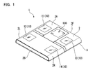
FIG. 1 is a schematic perspective view showing an appearance of a measuring device according to an embodiment of the present invention; -
FIG. 2 is a schematic exploded perspective view showing the structure of the measuring device; -
FIG. 3 is a schematic perspective view showing a state in which a second housing and connecting members in the measuring device are assembled together; -
FIG. 4 is a schematic top plan view of the measuring device; -
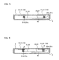
FIG. 5 is a schematic cross-sectional view of the measuring device taken along line A-A ofFIG. 4 ; -
FIG. 6 is a schematic cross-sectional view of a modified example of the measuring device taken along line A-A ofFIG. 4 ; -
FIG. 7 is a schematic perspective view of a further modified example of the measuring device; and -
FIG. 8 is a schematic perspective view of a connecting member in the further modified example of the measuring device. - A
measuring device 1 according to an exemplary embodiment of the present invention will be described with reference toFIG. 1 to FIG. 8 .FIG. 1 is a schematic perspective view showing an appearance of themeasuring device 1, whileFIG. 2 is a schematic exploded perspective view showing the structure of themeasuring device 1. As shown inFIG. 1 andFIG. 2 , themeasuring device 1 comprises: afirst housing 2 having a plurality of measuringelectrodes 10 on an upper surface thereof; asecond housing 3 connected to thefirst housing 2 and housing asubstrate 40 therein; and a plurality of connectingmembers first housing 2 and thesecond housing 3. - The
first housing 2 comprises: atop plate 2A formed in a square shape in top view; and aleft side wall 2L, aright side wall 2R, afront wall 2F and aback wall 2B which respectively extend downward from thetop plate 2A. Note that in the following description, the direction extending from thefront wall 2F to theback wall 2B (i.e. the direction in which a user commonly steps on and off when using it) will be referred to as front-back direction. More specifically, the side where thefront wall 2F is positioned will be expressed as e.g. front or front side, while the side where theback wall 2B is positioned will be expressed as e.g. back or back side. - The
top plate 2A and each of theleft side wall 2L and theright side wall 2R form a connecting portion therebetween having a curved shape. More specifically, the connecting portion between thetop plate 2A and theleft side wall 2L is gradually curved from thetop plate 2A toward theleft side wall 2L, and similarly the connecting portion between thetop plate 2A and theright side wall 2R is gradually curved from thetop plate 2A toward theright side wall 2R. Thetop plate 2A and each of thefront wall 2F and theback wall 2B intersect substantially perpendicular to each other. Each of thefront wall 2F and theback wall 2B has two upper corner portions, each of which is formed to have a curved shape when viewed in the front-back direction. In other words, the two upper corner portions are formed in an arc corresponding to the curved shape formed between thetop plate 2A and each of theside walls front wall 2F and theback wall 2B has two lower corner portions, each of which is formed to make a substantially right angle when viewed in the front-back direction. - Here, the area under the
top plate 2A that is surrounded by thefront wall 2F, theback wall 2B, theleft side wall 2L and theright side wall 2R is referred to asspace S 1. The space S1 opens downward. Further, thefront wall 2F, theback wall 2B, theleft side wall 2L and theright side wall 2R are set to have the same vertical dimension as each other. Thefirst housing 2 having the above structure is integrally formed, for example, of a resin material. Furthermore, thetop plate 2A has the plurality of measuringelectrodes 10 formed thereon which are placed in contact with a human body to be measured for various measurements. Each of themeasuring electrodes 10 comprises an electrode member having a square shape in top view and formed in a thin plate shape. Fourmeasuring electrodes 10 are provided near the four corners of thetop plate 2A, respectively. - More specifically, the
measuring electrodes 10 comprise: afirst measuring electrode 11 and asecond measuring electrode 12 arranged in the front-back direction along one side of thetop plate 2A close to theleft side wall 2L; and a third measuringelectrode 13 and afourth measuring electrode 14 arranged in the front-back direction along one side of thetop plate 2A close to theright side wall 2R. The first measuringelectrode 11 and the third measuringelectrode 13 are electrodes for supplying current. In other words, a current supplied by a current supply device (not shown) flows between thefirst measuring electrode 11 and the third measuringelectrode 13, and flows into the body of the user. - On the other hand, the second measuring
electrode 12 and thefourth measuring electrode 14 are electrodes used for making measurements. When current flows between the first measuringelectrode 11 and the third measuringelectrode 13 as described above, a potential difference is generated between the second measuringelectrode 12 and thefourth electrode 14. This potential difference is detected by thesecond measuring electrode 12 and thefourth measuring electrode 14. The first measuringelectrode 11 and the third measuringelectrode 13 are spaced from thesecond measuring electrode 12 and thefourth measuring electrode 14, respectively, by a predetermined distance. More specifically, the distance S between one side of the first measuring electrode 11 (the third measuring electrode 13) and one side of the second measuring electrode 12 (the fourth measuring electrode 14), facing the one side of the first measuring electrode 11 (the third measuring electrode 13), is, for example, about 70mm. - Each of the
measuring electrodes 10 has an upper surface formed in a smooth flat surface and exposed outward from above thetop plate 2A. Further, eachmeasuring electrode 10 has a lower surface formed in a smooth flat surface and exposed toward the above-described space S1 from below thetop plate 2A. In other words, each measuringelectrode 10 is arranged to penetrate through thetop plate 2A in the thickness direction. Note that eachmeasuring electrode 10 is fixed to thetop plate 2A by a fixing member (not shown) so as to prevent the measuringelectrode 10 from dropping off. Although eachmeasuring electrode 10 described above is arranged to penetrate through thetop plate 2A in the thickness direction, it is also possible to form a recess in an upper surface of thetop plate 2A, and to form, in a portion of the recess, a through-hole extending through a lower surface of thetop plate 2A, so as to place the measuringelectrode 10 in the recess. - The upper surface of each measuring
electrode 10 and the upper surface of thetop plate 2A are formed so as to be smoothly connected to each other. This makes it possible to make measurements without causing a raised portion of the measuringelectrode 10 to put unnecessary pressure on a human body when the measuringelectrode 10 is in contact with the human body, and also makes it possible to ensure aesthetic appearance of products. Adisplay window 100 is provided in an area of thetop plate 2A between thefirst electrode 11 and thethird electrode 13. At least a part of thedisplay window 100 is formed of a transparent resin, glass or the like so as to inform measurement results displayed on adisplay unit 45, which is provided on asubstrate 40 described later, to the outside through thedisplay window 100. - The
second housing 3 is a box-shaped member having a base and is connected to the above-describedfirst housing 2 in the vertical direction. Thesecond housing 3 comprises: a bottom plate 3U formed in a substantially square shape in top view; and a secondhousing front wall 3F, a second housing backwall 3B, a second housing leftside wall 3L and a second housingright side wall 3R which extend upward respectively from the bottom plate 3U and substantially perpendicular to the bottom plate 3U. The secondhousing front wall 3F, the second housing backwall 3B, the second housing leftside wall 3L and the second housingright side wall 3R are set to have substantially the same vertical dimension as that of thefront wall 2F, theback wall 2B, theleft side wall 2L and theright side wall 2R of thefirst housing 2, respectively. - Here, the area over the bottom plate 3U of the
second case 3 and surrounded by the secondhousing front wall 3F, the second housing backwall 3B, the second housing leftside wall 3L and the second housingright side wall 3R is referred to as space S2. The space S2 is divided into a plurality of sections by a plurality oflongitudinal ribs 61 extending in the front-back direction and a plurality oflateral ribs 62 extending in a direction perpendicular to thelongitudinal ribs 61. Thelongitudinal ribs 61 and thelateral ribs 62 are plate-like members extending upward respectively from the bottom plate 3U. When the user steps on themeasuring device 1, thelongitudinal ribs 61 and thelateral ribs 62 can withstand the load (weight of the user), since the space S2 is divided by the plurality oflongitudinal ribs 61 andlateral ribs 62. Thus, the space S2 is not broken by the weight of the user, allowing the measuringdevice 1 to maintain its shape. Note that a front area of the space S2 is not provided with either thelongitudinal ribs 61 or thelateral ribs 62, and is used as a substrate housing section S3. Asubstrate 40 described later is housed in the substrate housing section S3, and, therefore, the shape and dimensions of the substrate housing section S3 are determined by the shape and dimensions of thesubstrate 40. In the present embodiment, the substrate housing section S3 is substantially square-shaped in top view. - The
substrate 40 comprises: a circuit (not shown) for conducting a measurement process by using signals obtained from the measuringelectrodes 10 described above; and adisplay unit 45 for displaying output results of the circuit. On thesubstrate 40,terminals electrodes 10 are input to theterminals members members second housing 3. Although thelongitudinal ribs 61 and thelateral ribs 62 are provided in the space S2 of thesecond housing 3 as described above, thelongitudinal ribs 61 and thelateral ribs 62 are notched to formhousing grooves 63 in the areas of the space S2 where the connectingmembers housing grooves 63 are linear grooves extending in the same plane along the direction from theterminals substrate 40 toward the first measuringelectrode 11, thesecond measuring electrode 12, thethird measuring electrode 13 and the fourth measuringelectrode 14, respectively. - More specifically, the
housing groove 63 from the terminal 41 toward the first measuringelectrode 11 extends substantially diagonally left forward from thesubstrate 40. Thehousing groove 63 from the terminal 42 toward thesecond measuring electrode 12 extends substantially diagonally left backward from thesubstrate 40. Thehousing groove 63 from the terminal 43 toward thethird measuring electrode 13 extends substantially diagonally right forward from thesubstrate 40. Further, thehousing groove 63 from the terminal 44 toward the fourth measuringelectrode 14 extends substantially diagonally right backward from thesubstrate 40. - A conductive
member holding member 63A is provided at an end of eachhousing groove 63, which is located opposite to where thesubstrate 40 is located. Each conductivemember holding member 63A is a substantially cylindrical-shaped boss portion which extends upward from the bottom plate 3U in the space S2. The conductivemember holding members 63A engage with and holdconductive members second case 3 and surrounded by the secondhousing front wall 3F, the second housing backwall 3B, the second housing leftside wall 3L and the second housingright side wall 3R. - The connecting
members members member 20, will be described in detail below as a representative. The connectingmember 20 comprises: aconductive member 20A which is a coil spring, as an elastic member, wound around an axis extending in a vertical direction (i.e. in the direction in which thefirst housing 2 is connected to the second housing 3); and alinear lead member 20B which extends from a lower end of theconductive member 20A in a direction perpendicular to the vertical direction and is integrally formed with theconductive member 20A. Theconductive member 20A (hence the connecting member 20) is elastically deformable in the vertical direction (i.e. in the direction in which the first housing is connected to the second housing), and is formed of a metal material having good conductivity. - In the following explanation, a process of assembling the measuring
device 1 will be described. First, thesecond housing 3 to constitute a lower part of the measuringdevice 1 is prepared. Subsequently, thesubstrate 40 and the connectingmembers second housing 3. Thesubstrate 40 is housed in the substrate housing section S3 described above, and is fixed therein by screws or the like, for example, so as to prevent thesubstrate 40 from falling off. The connectingmembers housing grooves 63, respectively, which are areas between thefirst housing 2 and thesecond housing 3. More specifically, thelead members members housing grooves 63, respectively, which are formed in the space S2 of thesecond housing 3. Further, theconductive members member holding members 63A, respectively. This is shown inFIG. 3 , which is a schematic perspective view showing a state in which thesecond housing 3 and the connectingmembers measuring device 1 according to the exemplary embodiment of the present invention are assembled together. Next, the ends of thelead members conductive members terminals substrate 40. - More specifically, the
conductive members member holding members 63A, respectively, from above so as to be held thereby. In other words, the dimensions in the radial directions of the conductivemember holding members 63A are set to be substantially the same as (i.e., completely the same as, a little larger than or a little smaller than) the inner diameters of the coil springs of theconductive members member holding member 63A can be designed to decrease from a lower end to an upper end of the conductivemember holding member 63A. Further note that it is also possible to house thesubstrate 40 and the connectingmembers housing grooves 63, respectively, after the connectingmembers terminals substrate 40, respectively, in advance. However, in terms of workability and quality, it is more desirable to connect the connectingmembers terminals substrate 40, respectively, after thesubstrate 40 is housed in the substrate housing section S3. - Next, the
first housing 2 is connected to thesecond housing 3. Note that the measuringelectrodes 10 described above are assumed to be fixed to thefirst housing 2 in advance of the connection. Thefirst housing 2 and thesecond housing 3 are connected together by connecting members (not shown). An example of such connecting member can be a combination of an elastically deformable locking claw and a locking hook engaged with the locking claw. It is also possible to provide one of thefirst housing 2 and thesecond housing 3 with screws and provide the other with screw holes to connect thefirst housing 2 and thesecond housing 3. Accordingly, the assembly of the measuringdevice 1 is completed.FIG. 4 is a schematic top plan view of the measuringdevice 1 thus assembled. As shown inFIG. 4 , the assembled measuringdevice 1 is structured such that, when viewed from the direction in which thefirst housing 2 is connected to thesecond housing 3, i.e. from the vertical direction, the positions where theconductive members electrode 11, thesecond measuring electrode 12, thethird measuring electrode 13 and the fourth measuringelectrode 14, respectively. - This will be described in more detail with reference to
FIG. 5 , which is a schematic cross-sectional view of the measuringdevice 1 taken along line A-A ofFIG. 4 . Note that thelongitudinal ribs 61 and thelateral ribs 62 are abbreviated inFIG. 5 . As shown inFIG. 5 , in the assembled measuringdevice 1, the upper ends of theconductive members electrode 11, thesecond measuring electrode 12, thethird measuring electrode 13 and the fourth measuringelectrode 14 of thefirst housing 2, respectively. In addition, each of theconductive members conductive members electrode 11, thesecond measuring electrode 12, thethird measuring electrode 13 and the fourth measuringelectrode 14 due to the elastic restoring force of themselves. Thus, the first measuringelectrode 11, thesecond measuring electrode 12, thethird measuring electrode 13 and the fourth measuringelectrode 14 are electrically connected to thesubstrate 40 through the connectingmembers - In the
measuring device 1 described above, theconductive members lead members members linear lead members conductive members device 1, theconductive members lead members conductive members lead members conductive members - Furthermore, in the
measuring device 1 according to the present embodiment, each of theconductive members electrode 11, thesecond measuring electrode 12, thethird measuring electrode 13 and the fourth measuringelectrode 14 provided on thefirst housing 2 are in contact with theconductive members first housing 2 to thesecond housing 3 from above, and that the state of contact can be maintained substantially permanently as long as the elastic restoring force of theconductive members device 1 can be stably used for a long time. - As described above, according to the
measuring device 1 of the present exemplary embodiment, the connectingmembers first housing 2 is connected to thesecond housing 3. Thus, only by connecting thefirst housing 2 and thesecond housing 3 to each other, the connectingmembers electrodes first housing 2. Further, the measuringdevice 1 of the present embodiment is designed so that the connectingmembers electrode 11, thesecond measuring electrode 12, thethird measuring electrode 13 and the fourth measuringelectrode 14, respectively, due to the elastic force of the connectingmembers electrodes members measuring device 1, and to use themeasuring device 1 stably for a long time, because, by not soldering, the joints between the measuringelectrodes members - Further, the measuring
device 1 described above is structured such that, when viewed from the direction in which thefirst housing 2 is connected to thesecond housing 3, i.e. from the vertical direction, the positions where theconductive members members second hosing 3 have overlaps with the positions of the first measuringelectrode 11, thesecond measuring electrode 12, thethird measuring electrode 13 and the fourth measuringelectrode 14, respectively. According to this structure, the positions where theconductive members electrodes device 1. - Further, the measuring
device 1 has a structure that the connectingmembers conductive members first housing 2 is connected to thesecond housing 3. According to this structure, due to the elastic restoring force of the coil springs (conductive members members conductive members electrode 11, thesecond measuring electrode 12, thethird measuring electrode 13 and the fourth measuringelectrode 14, respectively, which are provided on thefirst housing 2. - In addition, in the
measuring device 1, the distances (lengths) from theconductive members terminals substrate 40, respectively, are designed to be the same as each other. - While an exemplary embodiment of the present invention has been described above in detail with reference to the drawings, the present invention is not limited to the embodiment described above, and is to cover all modifications and variations without departing from the spirit of the present invention. For example, in the embodiment described above, each measuring
electrode 10 has a lower surface formed in a smooth flat surface. Instead, however, recesses R can be formed each in the lower surface of eachelectrode 10 as shown inFIG. 6 , which is a schematic cross-sectional view of a modified example of the measuringdevice 1 taken along line A-A ofFIG. 4 . Each of the recesses R is formed to be recessed upward from the lower surface of the measuringelectrode 10. In this case, the recesses R are formed to be slightly larger than the outer dimensions of theconductive members - In other words, the recesses R have shapes corresponding to shapes of the upper ends of the connecting
members conductive members electrodes 10 are provided with the recesses R having shapes corresponding to the upper ends of the connectingmembers conductive members electrodes 10, respectively. This makes it possible to reduce slippage between theconductive members electrodes 10. Note that thelongitudinal ribs 61 and thelateral ribs 62 are abbreviated inFIG. 6 . - Further, in the embodiment described above, each of the
conductive members conductive members first housing 2 is connected to thesecond housing 3 as described below with reference toFIG. 7 and FIG 8. FIG. 7 is a schematic perspective view of a further modified example of the measuringdevice 1, whileFIG. 8 is a schematic perspective view of a connectingmember 200 in the further modified example of the measuringdevice 1. InFIG. 8 , the connectingmember 200 is shown as a representative of four connectingmembers members - As shown in
FIG. 7 and FIG. 8 , theconductive members conductive members first housing 2 is connected to thesecond housing 3. Note that the connectingmembers members member 200, will be described in detail below as a representative. - The connecting
member 200 comprises alead member 200B formed in a strip shape, and aconductive member 200A which is a leaf spring integrally formed with thelead member 200B. More specifically, as shown inFIG. 8 , theconductive member 200A has aninclined part 201A bent at a predetermined inclination angle relative to thelead member 200B, which extends linearly, so as to extend diagonally upward. Theconductive member 200A further has alinear part 202A bent at a predetermined inclination angle relative to theinclined part 201A so as to extend diagonally upward at a slight inclination angle relative to thelead member 200B. - Here, when a load is applied to the
linear part 202A from above, thelinear part 202A functions as a leaf spring due to the elastic restoring force of theconductive member 200A, since thelinear part 202A extends diagonally upward at a slight inclination angle relative to thelead member 200B. Further, the connectingmember 200 has a width dimension set to be slightly smaller than the width dimension of thehousing groove 63 described above. Thus, the connectingmember 200 can be housed in thehousing groove 63. According to this structure, similarly as in the embodiment described above, the connectingmember 200 is formed of a unitary member having theconductive member 200A and thelead member 200B integral with theconductive member 200A. Thus, when assembling the measuringdevice 1, theconductive member 200A can be connected to thelead member 200B without soldering, so that the assembly process of the measuringdevice 1 can be simplified. - According to this structure, similarly as in the embodiment described above, only by connecting the
first housing 2 to thesecond housing 3 from above, the ends of the connectingmembers conductive members electrode 11, thesecond measuring electrode 12, thethird measuring electrode 13 and the fourth measuringelectrode 14, respectively, which are provided on thefirst housing 2, due to the elastic restoring force of theconductive members conductive members device 1 can be stably used for a long time.
Claims (9)
- A measuring device (1) comprising:a first housing (2) having at least one measuring electrode (10, 11, 12, 13, 14);a second housing (3) connected to the first housing and housing a substrate (40) which has at least one terminal (41, 42, 43, 44) and including a circuit that conducts a measurement process; andat least one connecting member (20, 21, 22, 23; 200, 210, 220, 230) disposed between the first housing and the second housing,wherein the at least one connecting member is formed of a unitary member, andwherein one end of the at least one connecting member is connected to the at least one terminal, while the other end of the at least one connecting member is in contact with the at least one measuring electrode due to an elastic force of the at least one connecting member itself.
- The measuring device (1) according to claim 1,
wherein the at least one connecting member is elastically deformable in a direction in which the first housing is connected to the second housing. - The measuring device (1) according to claim 1 or 2,
wherein the at least one measuring electrode comprises a recess (R) having a shape corresponding to a shape of an end of the at least one connecting member, which end is in contact with the at least one measuring electrode. - The measuring device (1) according to any one of claims 1 to 3,
wherein, when viewed from a direction in which the first housing is connected to the second housing, a position where the at least one connecting member is held in the second housing has an overlap with a position of the at least one measuring electrode. - The measuring device (1) according to any one of claims 1 to 4,
wherein the at least one connecting member comprises a coil spring (20A, 21A, 22A, 23A) wound around an axis extending in a direction in which the first housing is connected to the second housing. - The measuring device (1) according to claim 5,
wherein the at least one connecting member further comprises a linear lead member (20B, 21B, 22B, 23B) integrally formed with the coil spring. - The measuring device (1) according to claim 6,
wherein the second housing comprises a housing groove (63) for housing the lead member. - The measuring device (1) according to any one of claims 1 to 4, wherein the at least one connecting member has, at one end thereof, a leaf spring (200A, 210A, 220A, 230A) which is elastically deformable in a direction in which the first housing is connected to the second housing.
- The measuring device (1) according to any one of claims 1 to 8,
wherein the at least one connecting member comprises a plurality of connecting members (20, 21, 22, 23; 200, 210, 220, 230),
wherein the at least one measuring electrode comprises a plurality of measuring electrodes (11, 12, 13, 14),
wherein the at least one terminal comprises a plurality of terminals (41, 42, 43, 44), and
wherein the plurality of connecting members have the same dimension as each other from the one end to the other end of each thereof.
Applications Claiming Priority (1)
| Application Number | Priority Date | Filing Date | Title |
|---|---|---|---|
| JP2014112355A JP5748018B1 (en) | 2014-05-30 | 2014-05-30 | measuring device |
Publications (2)
| Publication Number | Publication Date |
|---|---|
| EP2950062A1 true EP2950062A1 (en) | 2015-12-02 |
| EP2950062B1 EP2950062B1 (en) | 2017-07-12 |
Family
ID=53180614
Family Applications (1)
| Application Number | Title | Priority Date | Filing Date |
|---|---|---|---|
| EP15168118.6A Active EP2950062B1 (en) | 2014-05-30 | 2015-05-19 | Measuring device |
Country Status (4)
| Country | Link |
|---|---|
| US (1) | US10028673B2 (en) |
| EP (1) | EP2950062B1 (en) |
| JP (1) | JP5748018B1 (en) |
| CN (1) | CN104970792A (en) |
Families Citing this family (4)
| Publication number | Priority date | Publication date | Assignee | Title |
|---|---|---|---|---|
| AU2016354667B2 (en) * | 2015-11-10 | 2022-07-14 | Impedimed Limited | Impedance measurement system |
| CN105550717A (en) * | 2016-02-23 | 2016-05-04 | 英华达(上海)科技有限公司 | Body fat measuring system and pairing method |
| CN105615872B (en) * | 2016-03-21 | 2019-06-21 | 缤刻普锐(北京)科技有限责任公司 | For measuring the device of human body information |
| TWI594728B (en) * | 2016-10-14 | 2017-08-11 | 麗寶大數據股份有限公司 | Carpet type body fat meter |
Citations (3)
| Publication number | Priority date | Publication date | Assignee | Title |
|---|---|---|---|---|
| EP1786107A1 (en) * | 2005-11-09 | 2007-05-16 | Diehl AKO Stiftung & Co. KG | Capacitive touch-sensitive switch |
| US20090085188A1 (en) * | 2007-09-27 | 2009-04-02 | Mitsubishi Electric Corporation | Power semiconductor module |
| JP2011185689A (en) | 2010-03-08 | 2011-09-22 | Yamato Scale Co Ltd | Weighing apparatus |
Family Cites Families (12)
| Publication number | Priority date | Publication date | Assignee | Title |
|---|---|---|---|---|
| JPH08181257A (en) | 1994-12-26 | 1996-07-12 | Asahi Denki Kogyo Kk | Integrated circuit positioning device and printed circuit board for mounting integrated circuit positioning device |
| US5886302A (en) * | 1995-02-08 | 1999-03-23 | Measurement Specialties, Inc. | Electrical weighing scale |
| JP3655854B2 (en) | 2001-08-15 | 2005-06-02 | 埼玉日本電気株式会社 | External connection terminal of electronic equipment |
| CN2623167Y (en) * | 2002-11-14 | 2004-07-07 | 精量电子(深圳)有限公司 | Fat balance with transparent electrode for human body |
| CN2757726Y (en) * | 2004-11-22 | 2006-02-15 | 苏州市易德龙电器有限公司 | Human body fat balance |
| JP2007117623A (en) * | 2005-10-31 | 2007-05-17 | Omron Healthcare Co Ltd | Body composition measurement apparatus |
| JP5004233B2 (en) * | 2007-11-08 | 2012-08-22 | 株式会社ヨコオ | Relay connector |
| JP5200703B2 (en) | 2008-07-03 | 2013-06-05 | オムロンヘルスケア株式会社 | Body body composition meter assembly method and body weight composition meter |
| JP3159881U (en) | 2010-03-23 | 2010-06-03 | オムロンヘルスケア株式会社 | Bioimpedance measurement device |
| JP5678448B2 (en) * | 2010-03-23 | 2015-03-04 | オムロンヘルスケア株式会社 | Bioimpedance measurement device |
| CN202230890U (en) * | 2011-06-28 | 2012-05-23 | 深圳市电连精密技术有限公司 | Rf mems switch |
| JP2014027186A (en) | 2012-07-27 | 2014-02-06 | Sharp Corp | Shield structure |
-
2014
- 2014-05-30 JP JP2014112355A patent/JP5748018B1/en active Active
-
2015
- 2015-05-13 US US14/711,629 patent/US10028673B2/en active Active
- 2015-05-19 EP EP15168118.6A patent/EP2950062B1/en active Active
- 2015-05-29 CN CN201510289358.5A patent/CN104970792A/en active Pending
Patent Citations (3)
| Publication number | Priority date | Publication date | Assignee | Title |
|---|---|---|---|---|
| EP1786107A1 (en) * | 2005-11-09 | 2007-05-16 | Diehl AKO Stiftung & Co. KG | Capacitive touch-sensitive switch |
| US20090085188A1 (en) * | 2007-09-27 | 2009-04-02 | Mitsubishi Electric Corporation | Power semiconductor module |
| JP2011185689A (en) | 2010-03-08 | 2011-09-22 | Yamato Scale Co Ltd | Weighing apparatus |
Also Published As
| Publication number | Publication date |
|---|---|
| CN104970792A (en) | 2015-10-14 |
| US10028673B2 (en) | 2018-07-24 |
| US20150342498A1 (en) | 2015-12-03 |
| EP2950062B1 (en) | 2017-07-12 |
| JP2015223490A (en) | 2015-12-14 |
| JP5748018B1 (en) | 2015-07-15 |
Similar Documents
| Publication | Publication Date | Title |
|---|---|---|
| JP6281539B2 (en) | Electric connector device for board connection | |
| EP2950062B1 (en) | Measuring device | |
| JP6498681B2 (en) | connector | |
| JP2015060764A (en) | Electric connector device for board connection | |
| JP2018063840A (en) | Power storage device | |
| JP2015207394A (en) | Battery connection body and battery pack with the same | |
| US9436861B2 (en) | Board connection structure and electronic device | |
| EP2267741A1 (en) | Slide operation type switch | |
| US7982372B2 (en) | Piezoelectric transformer having a recess to surely maintain a position of an elastic member press-fitted between an electrode and a terminal | |
| JP2014053223A (en) | Coaxial connector | |
| KR20170097660A (en) | Externally-attached ptc element, and cylindrical battery | |
| JP6564286B2 (en) | Plug connector, plug connector unit, and connector device | |
| JP5114297B2 (en) | Ground bar and cable assembly | |
| JP5778940B2 (en) | Housing connection structure | |
| TWI888687B (en) | Input device and switch assembly thereof | |
| WO2020045066A1 (en) | Probe pin housing, inspection tool, inspection unit, and inspection device | |
| JP2017016843A (en) | connector | |
| JP4820588B2 (en) | Pressure sensor | |
| JP2013140705A (en) | Terminal block with measuring function | |
| JP6868153B2 (en) | Communication device | |
| JP6769464B2 (en) | Board connection structure and electronic equipment | |
| JP2018064056A (en) | Substrate holding device | |
| JP5284894B2 (en) | Edge connector and semiconductor test apparatus | |
| JP6173189B2 (en) | Sensor | |
| JP2011198679A (en) | Electronic equipment |
Legal Events
| Date | Code | Title | Description |
|---|---|---|---|
| 17P | Request for examination filed |
Effective date: 20150519 |
|
| AK | Designated contracting states |
Kind code of ref document: A1 Designated state(s): AL AT BE BG CH CY CZ DE DK EE ES FI FR GB GR HR HU IE IS IT LI LT LU LV MC MK MT NL NO PL PT RO RS SE SI SK SM TR |
|
| AX | Request for extension of the european patent |
Extension state: BA ME |
|
| PUAI | Public reference made under article 153(3) epc to a published international application that has entered the european phase |
Free format text: ORIGINAL CODE: 0009012 |
|
| RBV | Designated contracting states (corrected) |
Designated state(s): AL AT BE BG CH CY CZ DE DK EE ES FI FR GB GR HR HU IE IS IT LI LT LU LV MC MK MT NL NO PL PT RO RS SE SI SK SM TR |
|
| GRAP | Despatch of communication of intention to grant a patent |
Free format text: ORIGINAL CODE: EPIDOSNIGR1 |
|
| INTG | Intention to grant announced |
Effective date: 20170103 |
|
| GRAS | Grant fee paid |
Free format text: ORIGINAL CODE: EPIDOSNIGR3 |
|
| GRAA | (expected) grant |
Free format text: ORIGINAL CODE: 0009210 |
|
| AK | Designated contracting states |
Kind code of ref document: B1 Designated state(s): AL AT BE BG CH CY CZ DE DK EE ES FI FR GB GR HR HU IE IS IT LI LT LU LV MC MK MT NL NO PL PT RO RS SE SI SK SM TR |
|
| REG | Reference to a national code |
Ref country code: GB Ref legal event code: FG4D |
|
| REG | Reference to a national code |
Ref country code: CH Ref legal event code: EP |
|
| REG | Reference to a national code |
Ref country code: AT Ref legal event code: REF Ref document number: 908788 Country of ref document: AT Kind code of ref document: T Effective date: 20170715 |
|
| REG | Reference to a national code |
Ref country code: IE Ref legal event code: FG4D |
|
| REG | Reference to a national code |
Ref country code: DE Ref legal event code: R096 Ref document number: 602015003495 Country of ref document: DE |
|
| REG | Reference to a national code |
Ref country code: NL Ref legal event code: MP Effective date: 20170712 |
|
| REG | Reference to a national code |
Ref country code: LT Ref legal event code: MG4D |
|
| REG | Reference to a national code |
Ref country code: AT Ref legal event code: MK05 Ref document number: 908788 Country of ref document: AT Kind code of ref document: T Effective date: 20170712 |
|
| PG25 | Lapsed in a contracting state [announced via postgrant information from national office to epo] |
Ref country code: NL Free format text: LAPSE BECAUSE OF FAILURE TO SUBMIT A TRANSLATION OF THE DESCRIPTION OR TO PAY THE FEE WITHIN THE PRESCRIBED TIME-LIMIT Effective date: 20170712 Ref country code: FI Free format text: LAPSE BECAUSE OF FAILURE TO SUBMIT A TRANSLATION OF THE DESCRIPTION OR TO PAY THE FEE WITHIN THE PRESCRIBED TIME-LIMIT Effective date: 20170712 Ref country code: HR Free format text: LAPSE BECAUSE OF FAILURE TO SUBMIT A TRANSLATION OF THE DESCRIPTION OR TO PAY THE FEE WITHIN THE PRESCRIBED TIME-LIMIT Effective date: 20170712 Ref country code: NO Free format text: LAPSE BECAUSE OF FAILURE TO SUBMIT A TRANSLATION OF THE DESCRIPTION OR TO PAY THE FEE WITHIN THE PRESCRIBED TIME-LIMIT Effective date: 20171012 Ref country code: AT Free format text: LAPSE BECAUSE OF FAILURE TO SUBMIT A TRANSLATION OF THE DESCRIPTION OR TO PAY THE FEE WITHIN THE PRESCRIBED TIME-LIMIT Effective date: 20170712 Ref country code: LT Free format text: LAPSE BECAUSE OF FAILURE TO SUBMIT A TRANSLATION OF THE DESCRIPTION OR TO PAY THE FEE WITHIN THE PRESCRIBED TIME-LIMIT Effective date: 20170712 Ref country code: SE Free format text: LAPSE BECAUSE OF FAILURE TO SUBMIT A TRANSLATION OF THE DESCRIPTION OR TO PAY THE FEE WITHIN THE PRESCRIBED TIME-LIMIT Effective date: 20170712 |
|
| PG25 | Lapsed in a contracting state [announced via postgrant information from national office to epo] |
Ref country code: IS Free format text: LAPSE BECAUSE OF FAILURE TO SUBMIT A TRANSLATION OF THE DESCRIPTION OR TO PAY THE FEE WITHIN THE PRESCRIBED TIME-LIMIT Effective date: 20171112 Ref country code: BG Free format text: LAPSE BECAUSE OF FAILURE TO SUBMIT A TRANSLATION OF THE DESCRIPTION OR TO PAY THE FEE WITHIN THE PRESCRIBED TIME-LIMIT Effective date: 20171012 Ref country code: ES Free format text: LAPSE BECAUSE OF FAILURE TO SUBMIT A TRANSLATION OF THE DESCRIPTION OR TO PAY THE FEE WITHIN THE PRESCRIBED TIME-LIMIT Effective date: 20170712 Ref country code: RS Free format text: LAPSE BECAUSE OF FAILURE TO SUBMIT A TRANSLATION OF THE DESCRIPTION OR TO PAY THE FEE WITHIN THE PRESCRIBED TIME-LIMIT Effective date: 20170712 Ref country code: PL Free format text: LAPSE BECAUSE OF FAILURE TO SUBMIT A TRANSLATION OF THE DESCRIPTION OR TO PAY THE FEE WITHIN THE PRESCRIBED TIME-LIMIT Effective date: 20170712 Ref country code: GR Free format text: LAPSE BECAUSE OF FAILURE TO SUBMIT A TRANSLATION OF THE DESCRIPTION OR TO PAY THE FEE WITHIN THE PRESCRIBED TIME-LIMIT Effective date: 20171013 Ref country code: LV Free format text: LAPSE BECAUSE OF FAILURE TO SUBMIT A TRANSLATION OF THE DESCRIPTION OR TO PAY THE FEE WITHIN THE PRESCRIBED TIME-LIMIT Effective date: 20170712 |
|
| REG | Reference to a national code |
Ref country code: DE Ref legal event code: R097 Ref document number: 602015003495 Country of ref document: DE |
|
| PG25 | Lapsed in a contracting state [announced via postgrant information from national office to epo] |
Ref country code: DK Free format text: LAPSE BECAUSE OF FAILURE TO SUBMIT A TRANSLATION OF THE DESCRIPTION OR TO PAY THE FEE WITHIN THE PRESCRIBED TIME-LIMIT Effective date: 20170712 Ref country code: RO Free format text: LAPSE BECAUSE OF FAILURE TO SUBMIT A TRANSLATION OF THE DESCRIPTION OR TO PAY THE FEE WITHIN THE PRESCRIBED TIME-LIMIT Effective date: 20170712 Ref country code: CZ Free format text: LAPSE BECAUSE OF FAILURE TO SUBMIT A TRANSLATION OF THE DESCRIPTION OR TO PAY THE FEE WITHIN THE PRESCRIBED TIME-LIMIT Effective date: 20170712 |
|
| PLBE | No opposition filed within time limit |
Free format text: ORIGINAL CODE: 0009261 |
|
| STAA | Information on the status of an ep patent application or granted ep patent |
Free format text: STATUS: NO OPPOSITION FILED WITHIN TIME LIMIT |
|
| REG | Reference to a national code |
Ref country code: FR Ref legal event code: PLFP Year of fee payment: 4 |
|
| PG25 | Lapsed in a contracting state [announced via postgrant information from national office to epo] |
Ref country code: SM Free format text: LAPSE BECAUSE OF FAILURE TO SUBMIT A TRANSLATION OF THE DESCRIPTION OR TO PAY THE FEE WITHIN THE PRESCRIBED TIME-LIMIT Effective date: 20170712 Ref country code: SK Free format text: LAPSE BECAUSE OF FAILURE TO SUBMIT A TRANSLATION OF THE DESCRIPTION OR TO PAY THE FEE WITHIN THE PRESCRIBED TIME-LIMIT Effective date: 20170712 Ref country code: IT Free format text: LAPSE BECAUSE OF FAILURE TO SUBMIT A TRANSLATION OF THE DESCRIPTION OR TO PAY THE FEE WITHIN THE PRESCRIBED TIME-LIMIT Effective date: 20170712 Ref country code: EE Free format text: LAPSE BECAUSE OF FAILURE TO SUBMIT A TRANSLATION OF THE DESCRIPTION OR TO PAY THE FEE WITHIN THE PRESCRIBED TIME-LIMIT Effective date: 20170712 |
|
| 26N | No opposition filed |
Effective date: 20180413 |
|
| PG25 | Lapsed in a contracting state [announced via postgrant information from national office to epo] |
Ref country code: SI Free format text: LAPSE BECAUSE OF FAILURE TO SUBMIT A TRANSLATION OF THE DESCRIPTION OR TO PAY THE FEE WITHIN THE PRESCRIBED TIME-LIMIT Effective date: 20170712 |
|
| REG | Reference to a national code |
Ref country code: CH Ref legal event code: PL |
|
| REG | Reference to a national code |
Ref country code: BE Ref legal event code: MM Effective date: 20180531 |
|
| PG25 | Lapsed in a contracting state [announced via postgrant information from national office to epo] |
Ref country code: MC Free format text: LAPSE BECAUSE OF FAILURE TO SUBMIT A TRANSLATION OF THE DESCRIPTION OR TO PAY THE FEE WITHIN THE PRESCRIBED TIME-LIMIT Effective date: 20170712 |
|
| REG | Reference to a national code |
Ref country code: IE Ref legal event code: MM4A |
|
| PG25 | Lapsed in a contracting state [announced via postgrant information from national office to epo] |
Ref country code: CH Free format text: LAPSE BECAUSE OF NON-PAYMENT OF DUE FEES Effective date: 20180531 Ref country code: LI Free format text: LAPSE BECAUSE OF NON-PAYMENT OF DUE FEES Effective date: 20180531 |
|
| PG25 | Lapsed in a contracting state [announced via postgrant information from national office to epo] |
Ref country code: LU Free format text: LAPSE BECAUSE OF NON-PAYMENT OF DUE FEES Effective date: 20180519 |
|
| PG25 | Lapsed in a contracting state [announced via postgrant information from national office to epo] |
Ref country code: IE Free format text: LAPSE BECAUSE OF NON-PAYMENT OF DUE FEES Effective date: 20180519 |
|
| PG25 | Lapsed in a contracting state [announced via postgrant information from national office to epo] |
Ref country code: BE Free format text: LAPSE BECAUSE OF NON-PAYMENT OF DUE FEES Effective date: 20180531 |
|
| PG25 | Lapsed in a contracting state [announced via postgrant information from national office to epo] |
Ref country code: MT Free format text: LAPSE BECAUSE OF NON-PAYMENT OF DUE FEES Effective date: 20180519 |
|
| PG25 | Lapsed in a contracting state [announced via postgrant information from national office to epo] |
Ref country code: TR Free format text: LAPSE BECAUSE OF FAILURE TO SUBMIT A TRANSLATION OF THE DESCRIPTION OR TO PAY THE FEE WITHIN THE PRESCRIBED TIME-LIMIT Effective date: 20170712 |
|
| PG25 | Lapsed in a contracting state [announced via postgrant information from national office to epo] |
Ref country code: PT Free format text: LAPSE BECAUSE OF FAILURE TO SUBMIT A TRANSLATION OF THE DESCRIPTION OR TO PAY THE FEE WITHIN THE PRESCRIBED TIME-LIMIT Effective date: 20170712 |
|
| PG25 | Lapsed in a contracting state [announced via postgrant information from national office to epo] |
Ref country code: HU Free format text: LAPSE BECAUSE OF FAILURE TO SUBMIT A TRANSLATION OF THE DESCRIPTION OR TO PAY THE FEE WITHIN THE PRESCRIBED TIME-LIMIT; INVALID AB INITIO Effective date: 20150519 Ref country code: CY Free format text: LAPSE BECAUSE OF FAILURE TO SUBMIT A TRANSLATION OF THE DESCRIPTION OR TO PAY THE FEE WITHIN THE PRESCRIBED TIME-LIMIT Effective date: 20170712 Ref country code: MK Free format text: LAPSE BECAUSE OF NON-PAYMENT OF DUE FEES Effective date: 20170712 |
|
| PG25 | Lapsed in a contracting state [announced via postgrant information from national office to epo] |
Ref country code: AL Free format text: LAPSE BECAUSE OF FAILURE TO SUBMIT A TRANSLATION OF THE DESCRIPTION OR TO PAY THE FEE WITHIN THE PRESCRIBED TIME-LIMIT Effective date: 20170712 |
|
| P01 | Opt-out of the competence of the unified patent court (upc) registered |
Effective date: 20230509 |
|
| PGFP | Annual fee paid to national office [announced via postgrant information from national office to epo] |
Ref country code: DE Payment date: 20250521 Year of fee payment: 11 |
|
| PGFP | Annual fee paid to national office [announced via postgrant information from national office to epo] |
Ref country code: GB Payment date: 20250527 Year of fee payment: 11 |
|
| PGFP | Annual fee paid to national office [announced via postgrant information from national office to epo] |
Ref country code: FR Payment date: 20250528 Year of fee payment: 11 |